
- Released At: 13-09-2023
- Page Views:
- Downloads:
- Table of Contents
- Related Documents
-
AD-Campus 6.2
Group-Based Policy Configuration Guide
Document version: 5W100-20230221
Copyright © 2023 New H3C Technologies Co., Ltd. All rights reserved.
No part of this manual may be reproduced or transmitted in any form or by any means without prior written consent of New H3C Technologies Co., Ltd.
Except for the trademarks of New H3C Technologies Co., Ltd., any trademarks that may be mentioned in this document are the property of their respective owners.
The information in this document is subject to change without notice.
Contents
Single-fabric networking schemes
Connections between servers and devices
IRF networking of spine devices
Software and hardware requirements
Resource and IP address planning
Log in to the AD-Campus configuration page
Configure user endpoint settings
Conversational forwarding entry learning for static ACs
Legacy automated device onboarding
Optimized automated device onboarding
Configure access network settings
Configure user access settings
Manage access scenarios (optional)
Set the maximum number of online endpoints supported by an account
Configure 802.1X authentication
Initiate 802.1X authentication
Configure MAC portal authentication
Create a BYOD-type security group
Enable MAC portal authentication
Initiate MAC portal authentication
Configure MAC authentication users
Configure authentication-free interfaces
Configure authentication-free VLAN pool
Add an authentication-free interface group
Add port isolation device group
Bind authentication-free interface group to security group
Deploy configuration to the devices
Configure static AC authentication
Add a static access interface group
Add port isolation device group
Issue the policy template to the leaf device group
Issue the policy template to the leaf downlink interface
Create a static Access VLAN pool
Create a Layer 2 network domain
User authentication and online
Configure web portal authentication
Configure the web portal template
Interface policy template (Web portal and MAC authentication)
Add a static access interface group
Deploy a policy to a leaf device group
Deploy a policy to a leaf downlink interface group
Create Layer 2 network domains and security groups
Deploy configuration to the leaf device
Configure the third-party authentication server
Guest access or access upon authentication failure
Access upon authentication failure
Configure the broadband IoT service
Fast online based on MAC address ranges
Fast online based on IP address ranges
Fast online based on endpoint identification
Keep broadband IoT endpoints online for a long time
Configure role-based access control
Verifying permission and domain management
Configure guest service parameters
User authentication and online
QR code registration and authentication
SMS message registration and authentication page
Configure direct connection between endpoints and leaf devices
Add members to an interface group
Configure an interface group deployment policy
Create a fail-permit Layer 2 network domain
Create a fail-permit security group
Configure fail-permit on leaf downlink interfaces
Interface policy template for 802.1X authentication
Interface policy template for MAC authentication
Deploy the policy template to the leaf downlink interface group
Configure fail-permit IT resource access settings
Configure the fail-permit DHCP server
Configure a tightly coupled Microsoft DHCP server
Configure a loosely coupled Microsoft DHCP server
Configure IT resource group access settings
Accessing external routers through a single border device
Associating the egress gateway with a private network
Egress gateway configuration deployed by the device
Configure the interface connecting the border device to the external network
Configure the L3 device connected to the border device
Accessing external route devices through dual border devices
Configure the L3 device connected to the border device
Restrictions and guidelines for the two-tier network configuration
Connection between Spine1 and L3 Switch
Connection between Spine2 and L3 Switch
Connection between Spine1 and Spine2
Configure routes from leaf and access devices to servers
Configure DRNI for dual spine devices (manual)
Connection between Spine1 and L3 switch
Restrictions and guidelines
1. The S5560X-EI and S6520X-EI series do not support microsegmentation.
2. You need to enable the S5560X/S6520X series switches to directly forward specific protocol packets (including ARP packets and MLD packets) received by VXLAN tunnel interfaces without delivering the packets to the CPU. This avoids the impact of the packets on the CPU. The configuration steps are as follows:
a. Configure the undo mac-address static source-check enable command globally.
b. If the flooding disable all all-direction or flooding disable broadcast all-direction command has been configured in VSI view, you need to delete the configuration by executing the undo flooding disable command in VSI view. Then, execute the flooding disable all or flooding disable broadcast command again.
c. Configure the forwarding vxlan-packet inner-protocol { ipv4 | ipv6 } command globally. If both IPv4 and IPv6 services are available, configure parameters for both IPv4 and IPv6.
d. Configure the port isolation group globally. Configure port isolation on downlink interfaces of all leafs. If traditional VLAN services need to be accessed between leaf downlink interfaces, you do not need to add them to port isolation groups. This might result in failure to isolate traffic of broadcast, unknown multicast, and unknown unicast between these leaf downlink interfaces.
3. The S5560X-EI/S5560X-HI/S6520X-EI/S6520X-HI devices cannot act as edge devices (EDs).
4. When the S5560X-HI/S6520X-HI devices act as the border device in gateway sharing mode, you need to configure PBR to permit return traffic on the interface.
5. To configure BYOD security groups, you must first configure the vDHCP server.
6. In the single leaf scenario, the controller does not automatically assign IP addresses to loopback interfaces. To support fabric interconnection services, you can edit the VTEP IP of the fabrics on the Web interface.
7. To connect an access device to a router, you must use a LAN interface rather than a WAN interface, and you must disable DHCP and NAT on the router.
8. In the public host scenario, the name-address binding feature supports only the 802.1X + iNode authentication mode. It does not support MAC portal authentication on public hosts shared by multiple user accounts.
9. The Microsoft DHCP server supports allocating IPv6 addresses only in loose coupling mode for standalone deployment.
10. The number of MAC-IP bindings in a single address pool of the Microsoft DHCP server must be smaller than 2000.
11. After the Microsoft DHCP server fails, the standby server cannot generate binding entries and can only allocate IP addresses. After the failure is recovered, the endpoints can be bound only after they go offline and then come online again for reauthentication.
12. When the default action of a group policy is configured as Deny, as a best practice, connect the physical servers of an IT resource group through spine devices and deploy them on the private network named vpn-default. If the IT resource groups are deployed on the private network named vpn-default, all private networks are allowed to access all IT resource groups by default. By configuring the IT resource groups that are not allowed to be accessed in each private network and deploying a group policy with the deny action, you can prohibit the access to resources. If an IT resource group is deployed in a service VPN, users in the service private network cannot access the IT resource group by default. To access the IT resource group, you must configure a policy with the permit action.
13. On the Layer 3 switch connected to a server, you must configure MSTP rather than PVST.
14. You must deploy a switch between the network port of a SeerBlade module and a spine device.
15. In a non-standard network, especially in a network containing firewalls, enable the corresponding ports as described in the port matrix documentation of the solution.
16. The user IP binding function is not allowed in an access policy when a secondary subnet is configured for a Layer 2 network domain.
17. The user authentication supports the 802.1X authentication mode and the MAC/MAC portal authentication mode. You need to configure only one authentication mode in actual networking. You can select an authentication mode as needed. As a best practice, do not configure both authentication modes unless required. However, the campus network supports configuring both authentication modes.
18. When you manually configure IRF fabrics for spine/leaf/access/AC devices, you must first execute the irf mac-address persistent always command to ensure that the bridge MAC address of the IRF fabric remains unchanged in the master/subordinate device switchover.
19. When a multicast source accesses a device in VLAN mode, it supports the *SH card of S12500G-AF and S10500/S10500X switch series, as well as S6550XE and S6525XE devices.
20. The DHCP server cannot be changed when a user is online.
21. A group of devices cannot be incorporated by multiple controllers at the same time.
22. A set of DHCP servers cannot be incorporated by multiple controllers at the same time.
23. In the case of ARP flooding, configure the attack prevention commands as recommended by the product.
24. When multiple security groups exist in the environment, as a best practice, enable the on-demand deployment function for ACs.
25. As a best practice, configure the arp send-gratuitous-arp interval command for VSI interface 4094 of the spine device to set the interval to 30 seconds.
26. The endpoint IP collision detection function on the DDI page in the Automation > Campus Network > Network Parameters > vDHCP path requires cooperation with the syslog function. For manually onboarded leaf devices, add the info-center loghost vpn-instance vpn-default 100.1.0.100 setting.
27. When adding a device to the monitoring list and issuing the snmp trap command, you need to configure VPN settings.
28. If a fabric contains both manually onboarded devices and automated onboarded devices (this hybrid device onboarding scenario is not recommended), make sure the IP addresses of VSI/VLAN 4094 in both onboarding methods are different. In addition, make sure the underlay IP address and underlay VLAN of the manually onboarded device are not within the underlay IP address and undelay VLAN ranges of the automation template.
29. When inter-device aggregation groups are added or deleted on the controller, the leaf device will temporarily become disconnected. This situation can be avoided by configuring the asymmetric IRB forwarding function (with the evpn irb asymmetric command) for the management network. In stable cases, you need to disable the asymmetric IRB forwarding function (with the undo evpn irb asymmetric command).
30. You cannot configure both name-address binding and IP source guard (IPv4 interface binding) or ARP detection.
31. In the DRNI networking, you need to manually specify a unique router ID for each DR device.
Overview
This document is intended to guide the basic deployment of the AD-Campus 6.2 solution through the following steps:
· Installation and deployment of associated software.
· Manual underlay configuration.
· Manual incorporation of physical devices.
· Basic service configuration and user configuration of SeerEngine-Campus controller.
· Wired user authentication and onboarding.
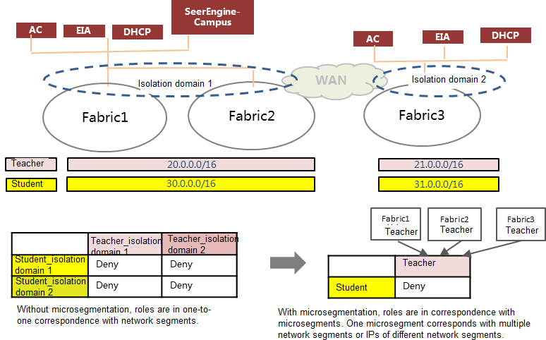
The AD-Campus 6.2 solution is implemented based on microsegmentation that defines microsegments as user roles or security groups, and supports security groups across isolation domains. The security group ID specified for a security group is the microsegment ID. A security group can be bound to Layer 2 network domains in multiple isolation domains, and different VXLAN IDs are deployed to the security group for different isolation domains.
The microsegmentation-based solution associates users with security groups, decouples users from IP address ranges, and implements the authentication and onboarding of the same user in different isolation domains through the user role-to-security group bindings. The solution implements service division based on user roles and global uniform policy enforcement when users move across isolation domains.
Because microsegmentation supports security groups across isolation domains, you do not need to configure inter-group policies for security groups based on each IP address range. In addition, microsegmentation supports sub security groups. A sub security group can inherit the permissions from its parent group, and you can also configure permissions for the sub group separately, realizing fine-grained permission control and assignment for user roles.
The service features are described in the associated documents, as shown in Table 1.
Table 1 Features and the associated documents
|
Feature |
Description |
Documents |
|
Automation |
Automated device deployment |
AD-Campus 6.2 Automation Configuration Guide AD-Campus 6.2 Optimized Automation Configuration Guide |
|
Semi-automation |
Manual incorporation of spine/leaf devices and automatic incorporation of access devices |
AD-Campus 6.2 Semi-Automation Configuration Guide |
|
Wireless |
AC incorporation and wireless user authentication and onboarding |
AD-Campus 6.2 Wireless Service Configuration Guide |
|
IPv6 |
IPv6 device incorporation and users' IPv6 address acquisition |
AD-Campus 6.2 IPv6 Service Configuration Guide |
|
Multiple campus interconnection |
Isolation domain interconnection and interconnection between an isolation domain and multiple fabrics |
AD-Campus 6.2 Multi-Campus Multi-Fabric Configuration Guide |
|
Microsoft DHCP |
Microsoft DHCP tight coupling environment setup and configuration |
AD-Campus 6.2 Tight Microsoft DHCP Management Configuration Guide |
|
Security convergence |
User device incorporation service |
AD-Campus 6.2 Security Convergence Configuration Guide |
|
EPON |
EPON network setup and service configuration |
AD-Campus 6.2 EPON Configuration Guide |
|
Replacement of faulty device |
Accurate replacement and heterogeneous replacement of faulty devices |
AD-Campus 6.2 Device Replacement Configuration Guide |
Single-fabric networking schemes
The networking models supported by the AD-Campus network solution include the dual-spine networking and IRF networking. In the dual-spine networking, two spines form a DR system or are dual-homed in the uplink for redundancy and load sharing. IRF networking virtualizes two devices into one device to achieve collaborative operation, unified management, and uninterrupted maintenance of multiple devices. According to the device architecture, the two models include the following networking schemes:
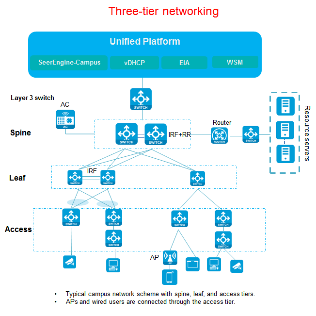
· Three-tier networking scheme—Contains the spine, leaf, and access tiers. It is a typical networking scheme in campus networks. The spine, leaf, and access devices support IRF fabrics. In addition, the access devices support multi-level cascade connections.
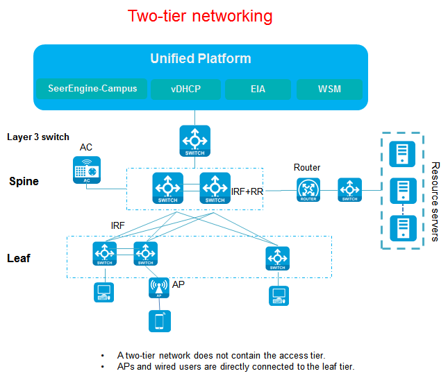
· Two-tier networking scheme—Contains the spine and leaf tiers, without access devices. Wireless APs and wired users are directly connected to leaf devices.
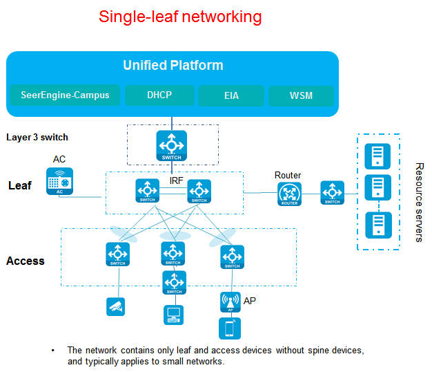
· Single-leaf networking scheme—Contains the leaf and access tiers, without spine devices. It is typically used in small networks. The network can contain one leaf device or two leaf devices in an IRF fabric. The access devices support IRF fabrics and multi-level cascade connections.
The three-tier, two-tier, and single-leaf networking schemes introduced in this document are for a single fabric. For more information about multi-fabric networking configurations, see AD-Campus 6.2 Multi-Campus Multi-Fabric Configuration Guide.
Dual-spine networking
Three-tier networking scheme
Figure 1 Three-tier networking scheme
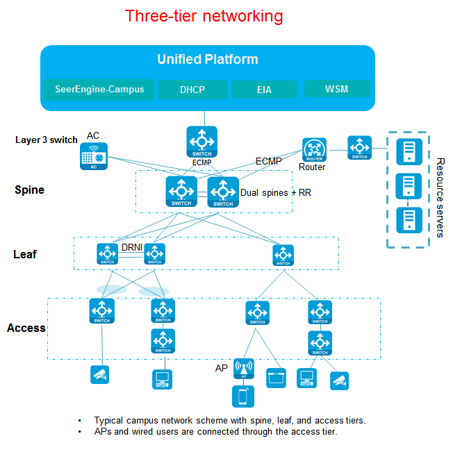
The three-tier networking scheme includes spine, leaf, and access devices. This is the typical networking of the AD-Campus solution.
Spine devices need to support VXLAN and typically act as route reflectors (RRs) and routing devices to forward routes between different leaf devices. They also act as border devices for communication with various types of servers. Dual-spine devices have two modes: DRNI networking and non-DRNI networking. For dual-spine devices, you do not need to configure DRNI in the wired scenario. If an AC is connected to the spine devices in hairpin mode, the two spine devices must form a DR system and communicate with AC through a DR interface. Leaf devices need to support VXLAN for user authentication and route forwarding. Access devices connect to APs and endpoints, and support multi-level cascade connections.
In the dual-spine scenario, incorporate spine devices manually. For more information, see "Configure dual spine uplink" or "Configure DRNI for dual spine devices (manual)."
Two-tier networking scheme
Figure 2 Two-tier networking scheme
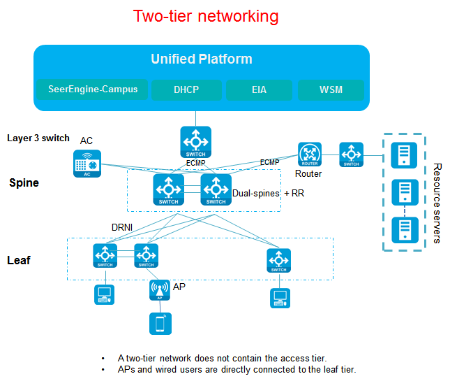
The two-tier networking scheme in the AD-Campus solution contains only spine and leaf devices without access devices. Wireless APs and wired users are directly connected to leaf devices. The interfaces connecting leaf devices to APs and users need to be configured manually.
Spine devices need to support VXLAN, and typically act as RRs and routing devices to forward routes between different leaf devices. They also act as border devices for communication with various types of servers. Dual-spine devices have two modes: DRNI networking and non-DRNI networking. For dual-spine devices, you do not need to configure DRNI in the wired scenario. If an AC is connected to the spine devices in hairpin mode, the two spine devices must form a DR system and communicate with the AC through a DR interface.
Single-leaf networking scheme
Figure 3 Single-leaf networking scheme
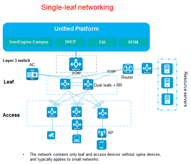
The single-leaf networking scheme contains only one leaf device (or two leafs that form an IRF fabric), without spine devices. Multiple access devices are connected to the leaf device or leaf IRF fabric. The network deployment is simple. This scheme is typically applicable to small-size networks. The leaf device (or leaf IRF fabric) implements the interworking between the border device and various servers. As a best practice, configure DRNI on the dual-leaf devices. If an AC is connected to the leaf devices in hairpin mode, the two leaf devices must form a DR system and communicate with the AC through a DR interface.
IRF networking
Three-tier networking scheme
Figure 4 Three-tier networking scheme
The three-tier networking scheme includes spine, leaf, and access devices. This is the typical networking of the AD-Campus solution.
Spine devices need to support VXLAN, and typically act as RRs and routing devices to forward routes between different leaf devices. They also act as border devices for communication with various types of servers. Spine devices support deployment in standalone mode and IRF mode.
Leaf devices need to support VXLAN for user authentication and route forwarding.
Access devices connect to APs and endpoints, and support multi-level cascade connections.
Two-tier networking scheme
Figure 5 Two-tier networking scheme
The two-tier networking scheme contains only spine and leaf devices without access devices. Wireless APs and wired users are directly connected to leaf devices. The interfaces connecting leaf devices to APs and users need to be configured manually.
Spine devices need to support VXLAN, and typically act as RRs and routing devices to forward routes between different leaf devices. They also act as border devices for communication with various types of servers. Spine devices support deployment in standalone mode and IRF mode.
Single-leaf networking scheme
Figure 6 Single-leaf networking scheme
The single-leaf networking scheme contains only one leaf device (or two leafs that form an IRF fabric), without spine devices. Multiple access devices are connected to the leaf device or leaf IRF fabric. The network deployment is simple. This scheme is typically applicable to small-size networks. The leaf devices act as border devices for communication with various types of servers and support deployment in standalone mode and IRF mode.
Aggregated three-tier/two-tier networking
Figure 7 Aggregated three-tier networking diagram
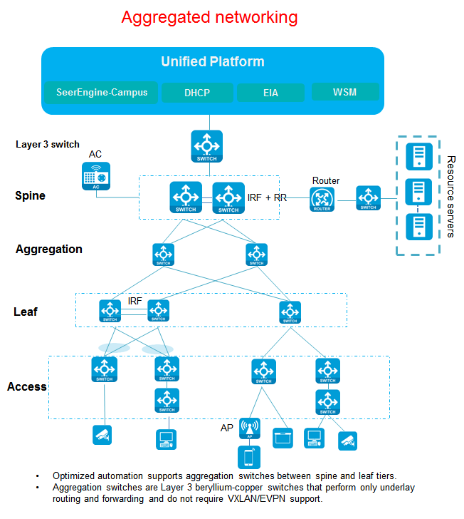
The aggregated three-tier/two-tier networking has the following features:
· Compared with the typical three-tier/two-tier networking, the aggregated network adds Layer 3 aggregation switches between the spine tier and the leaf tier, which eliminates the need for VXLAN/EVPN.
· Spine/leaf/access supports standalone or IRF architecture.
· The spine/leaf tier and the aggregation tier are connected through multiple links to form equal-cost multi-path (ECMP) routing.
· The leaf and access tiers are connected through multiple links to implement link aggregation.
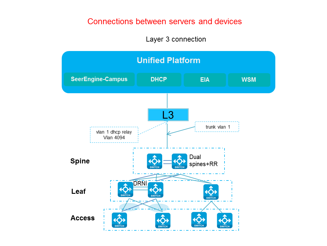
Connections between servers and devices
The three networking schemes introduced previously are based on the connection modes of the spine, leaf, and access devices, and are the basic networking schemes in a single fabric for the AD-Campus solution.
This section describes the connections between Unified Platform and its components (including SeerEngine-Campus, vDHCP Server, and EIA) and switches, that is, Layer 3 network connections.
The management IP addresses of the controller and the switch belong to different network segments, and they reach each other through Layer 3 routing. The controller can be deployed at the remote end or local end (the controller and the devices do not need to be in the same Layer 2 network domain, and they only require Layer 3 connectivity). Either one or two NICs are needed for deployment. If you use one NIC for deployment, the SeerEngine-Campus and Unified Platform share the NIC. If you use two NICs for deployment, the SeerEngine-Campus and Unified Platform each use one NIC separately.
Dual-spine networking
Figure 8 Server-device connections through dual-spine devices
IRF networking of spine devices
Figure 9 Server-device connections through the IRF fabric of spine devices

Networking configuration
1. In the AD-Campus network, the SeerEngine-Campus, DHCP server, and network devices are interconnected at Layer 3. Only one uplink is required between the spine device and the server, and you need to execute the port trunk permit vlan1 4094 command for the link.
2. Spine devices need to support VXLAN, and act as RRs and routing devices to forward routes between different leaf devices. They also act as border devices for communication with various types of servers. The link between the spine and leaf devices is an underlay link. You only need to make sure the route between the spine and leaf devices is reachable.
3. A leaf device uses a downlink interface to connect to an access device. The leaf downlink interface performs user authentication. When users come online, the leaf device identifies different access interfaces by downlink interface + VLAN ID and assigns users to different user security groups according based on login accounts.
4. Access devices operate at Layer 2 and are typically connected to endpoints. The links between access and leaf devices are connected through the Access uplink interfaces, and the uplink interfaces are configured as trunk ports permitting all VLANs by using the port trunk permit vlan all command. Access devices support cascade connections of up to three levels. You must use GE interfaces for cascade connections between access devices during automated deployment.
5. The SeerEngine-Campus controller assigns a VLAN ID (starting from VLAN 101) to each downlink interface of the access device to mark the location of each endpoint. For access devices in multi-level cascade connections, the controller assigns VLAN IDs incrementally to them. For example, for access devices of two levels of cascade connections, the controller assigns VLAN 101 to VLAN 152 to access devices of the first level, and assigns VLAN IDs starting from VLAN 153 to access devices of the second level. For access devices connected to different downlink interfaces of the same leaf, the controller assigns a VLAN ID starting from VLAN 101 to each access device.
6. Configure the interface on the access device connected to a user endpoint as an edge port by using the stp edged-port command.
#
interface GigabitEthernet1/0/31
port link-mode bridge
port access vlan 130
stp edged-port
#
|
|
IMPORTANT: The stp edged-port command is issued to the access device interface connected to the endpoint after the access device is incorporated. The stp edged-port command is not deleted automatically if a link between the access and leaf devices is added later. You must manually delete the command. |
Configuration workflow
The AD-Campus 6.2 solution requires underlay configuration, device incorporation, overlay configuration, and user authentication configuration.
· The underlay configuration is the basis before the device incorporation, and it is typically related to the device physical connection configuration through automatic onboarding or manual configuration.
· The overlay configuration is related to user services, including the creation of private networks, Layer 2 network domains, and security groups, as well as configurations of inter-group policies and service chains.
· The user authentication configurations include user management, access policies, and access services. The user authentication configuration is implemented through the EIA authentication server.
Both SeerEngine-Campus and EIA environments support standalone deployment and cluster deployment. For more information, see AD-Campus 6.2 Unified Platform and Deployment Guide.
Figure 10 Configuration workflow

|
|
IMPORTANT: Perform underlay configuration through automated device deployment or manual configuration. · For information about automated device deployment, see AD-Campus 6.2 Automation Configuration Guide. · For information about manual configuration, see 0"Manually incorporate a device." |
Software and hardware requirements
Application requirements
Table 2 Application requirements
|
Product |
Name |
Description |
Remarks |
|
Unified Platform |
GlusterFS |
Provides the local shared storage function within the product |
Required |
|
Portal |
Portal, unified authentication, user management, service gateway, and help center |
Required |
|
|
Kernel |
Permission, resource identity, License, configuration center, resource groups, and log services |
Required |
|
|
Kernel-base |
Alarms, access parameter templates, monitor templates, reports, and email & SMS forwarding services |
Required |
|
|
Network |
Basic network management (network resources, network performance, network topology, and iCC) |
Required |
|
|
Kernel-region |
Hierarchical management |
Optional |
|
|
Dashboard |
Provides a dashboard frame |
Required |
|
|
Widget |
Provides widgets for the dashboard |
Required |
|
|
Syslog |
Provides syslog functions and log center |
Optional |
|
|
Websocket |
Provides the legacy device automation function and optimized automation function |
Required |
|
|
Components required for campus scenarios |
SeerEngine-Campus |
Campus network management controller, providing basic campus service configuration |
Required |
|
vDHCP |
DHCP server, automatically onboarding devices and allocating addresses to end users |
Required |
|
|
EIA |
End-user intelligent access, providing user authentication service configuration |
Required |
|
|
WSM |
Wireless management platform, providing wireless access services |
Optional |
|
|
EAD |
Endpoint access control platform, controlling endpoint access |
Optional |
|
|
EPS |
Endpoint profiling system, which actively identifies endpoints and detects endpoint access |
Optional |
|
|
SeerAnalyzer |
Network data collection and analysis |
Optional |
|
|
SMP |
Provides the firewall management function |
Optional |
|
|
DHCP server supporting tight coupling |
vDHCP Server |
H3C DHCP server |
Required |
|
Microsoft DHCP Server |
Supports tight and loose coupling |
N/A |
Hardware requirements
Table 3 Supported device models and roles
|
Default role |
Other roles supported |
|
|
S12500G-AF |
Spine |
Leaf/Access |
|
S10500X/S10500 |
Spine |
Leaf/Access |
|
S7500X |
Leaf |
Spice/Access |
|
S6550XE-HI |
Leaf |
Access |
|
S6525XE-HI |
Leaf |
Access |
|
S6520X-HI |
Leaf |
Access |
|
S5560X-HI |
Leaf |
Access |
|
S6520X-EI (microsegmentation not supported) |
Leaf |
Access |
|
S5560X-EI (microsegmentation not supported) |
Leaf |
Access |
|
S6520X-SI |
Access |
N/A |
|
S5130-EI S5130-HI S5130S-EI S5130S-HI |
Access |
N/A |
Resource and IP address planning
Service resource planning
The intermediate switch between the server and devices is called the L3 switch. Whether devices are onboarded automatically or manually, the manual configuration is required on the intermediate L3 switch to ensure connectivity between the devices and the controller.
Before configuration, prepare the network. The SeerEngine-Campus controller and Unified Platform can share one network adapter or use different network adapters.
|
|
IMPORTANT: As a best practice, use IP addresses of different subnets for EIA and VLAN 4094. |
Dual-homed spines
The SeerEngine-Campus controller and Unified Platform share one network adapter
Figure 11 The SeerEngine-Campus controller and Unified Platform share one network adapter
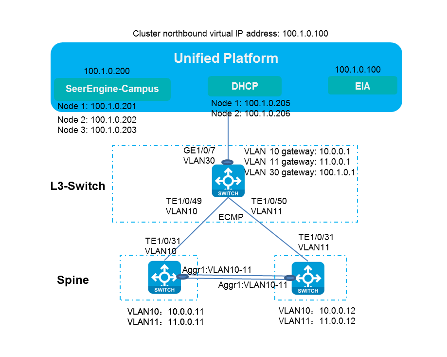
Table 4 List of server IP addresses and Layer 3 switch network planning
|
Item |
Example |
Remarks |
|
VLAN 1 network segment (gateway) |
120.1.0.0/24 (120.1.0.1) |
VLAN 1 network for automated deployment |
|
VLAN 4094 network segment (gateway) |
130.1.0.0/24 (130.1.0.1) |
VLAN 4094 network for communication between the controller and devices |
|
VLAN 10 network segment (gateway) |
10.0.0.0/24 (10.0.0.1) |
VLAN 10 for interconnection with the spine device at Layer 3 |
|
VLAN 11 network segment (gateway) |
11.0.0.0/24 (11.0.0.1) |
VLAN 11 for interconnection with the spine device at Layer 3 |
|
VLAN 30 network segment (gateway) |
100.1.0.0/24 (100.1.0.1) |
Network segment used by Unified Platform, SeerEngine-Campus, and vDHCP |
|
Network segment of the Underlay IP address |
200.1.1.0/24 |
Network segment of loopback interface IP addresses on spine and leaf devices |
|
Unified Platform northbound service IP address |
100.1.0.100 |
The address used for logging in to Unified Platform |
|
EIA |
100.1.0.100 |
EIA server IP address that is the northbound service IP address of Unified Platform during converged deployment |
|
SeerEngine-Campus cluster IP address |
100.1.0.200 |
SeerEngine-Campus cluster IP address |
|
SeerEngine-Campus node IP addresses |
Node 1: 100.1.0.201 Node 2: 100.1.0.202 Node 3: 100.1.0.203 |
SeerEngine-Campus node IP addresses |
|
vDHCP cluster IP address |
100.1.0.204 |
Cluster IP address of the vDHCP server (not used actually) |
|
vDHCP node IP addresses |
Node 1: 100.1.0.205 Node 2: 100.1.0.206 |
IP addresses of the two nodes in the vDHCP server |
|
IP address of Microsoft DHCP |
8.0.1.171 |
IP address of the Microsoft DHCP server |
The SeerEngine-Campus controller and Unified Platform use different network adapters
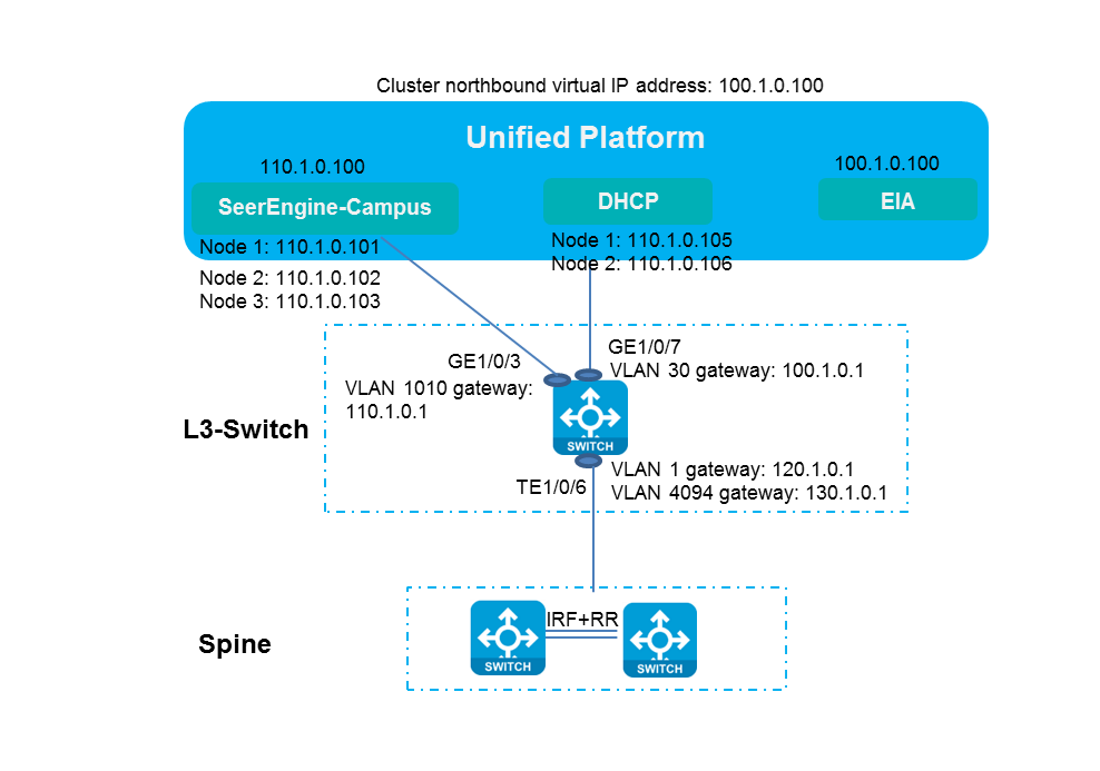
Figure 12 The SeerEngine-Campus controller and Unified Platform use different network adapters
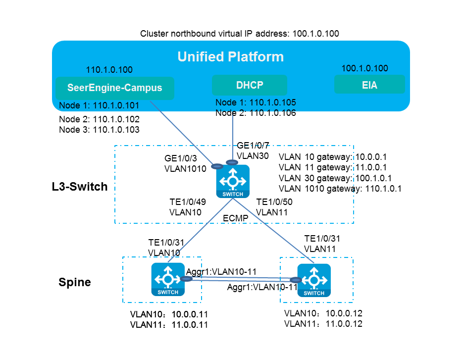
In this example, the SeerEngine-Campus controller and Unified Platform use one NIC respectively. Table 5 shows the address planning.
Table 5 List of server IP addresses and Layer 3 switch network planning
|
Item |
Example |
Remarks |
|
VLAN 1 network segment (gateway) |
120.1.0.0/24 (120.1.0.1) |
VLAN 1 network for automated deployment |
|
VLAN 4094 network segment (gateway) |
130.1.0.0/24 (130.1.0.1) |
VLAN 4094 network for communication between the controller and devices |
|
VLAN 10 network segment (gateway) |
10.0.0.0/24 (10.0.0.1) |
VLAN 10 for interconnection with the spine device at Layer 3 |
|
VLAN 11 network segment (gateway) |
11.0.0.0/24 (11.0.0.1) |
VLAN 11 for interconnection with the spine device at Layer 3 |
|
VLAN 30 network segment (gateway) |
100.1.0.0/24 (100.1.0.1) |
Network segment used by Unified Platform for communication with PCs |
|
VLAN 1010 (gateway) |
110.1.0.0/24 (110.1.0.1) |
Network segment used by SeerEngine-Campus and vDHCP for communication between the controller and PCs (configured when SeerEngine-Campus uses an independent network adapter) |
|
Network segment of the Underlay IP address |
200.1.1.0/24 |
Network segment of the loopback interface IP addresses on spine and leaf devices |
|
Unified Platform northbound service IP address |
100.1.0.100 |
The address used for logging in to Unified Platform |
|
EIA |
100.1.0.100 |
IP address of the EIA server |
|
SeerEngine-Campus cluster IP address |
110.1.0.100 |
SeerEngine-Campus cluster IP address |
|
SeerEngine-Campus node IP addresses |
Node 1: 110.1.0.101 Node 2: 110.1.0.102 Node 3: 110.1.0.103 |
SeerEngine-Campus node IP addresses |
|
vDHCP cluster IP address |
110.1.0.104 |
Cluster IP address of the vDHCP server (not used actually) |
|
vDHCP node IP addresses |
Node 1: 110.1.0.105 Node 2: 110.1.0.106 |
IP addresses of the two nodes in the vDHCP server |
|
IP address of Microsoft DHCP |
8.0.1.171 |
IP address of the Microsoft DHCP server |
Dual-homed spines in an IRF fabric
The SeerEngine-Campus controller and Unified Platform share one network adapter
The SeerEngine-Campus controller and Unified Platform can share a single NIC. In this case, Unified Platform, SeerEngine-Campus, vDHCP, and EIA use the IP addresses within the same network segment.
Figure 13 The SeerEngine-Campus controller and Unified Platform share one network adapter
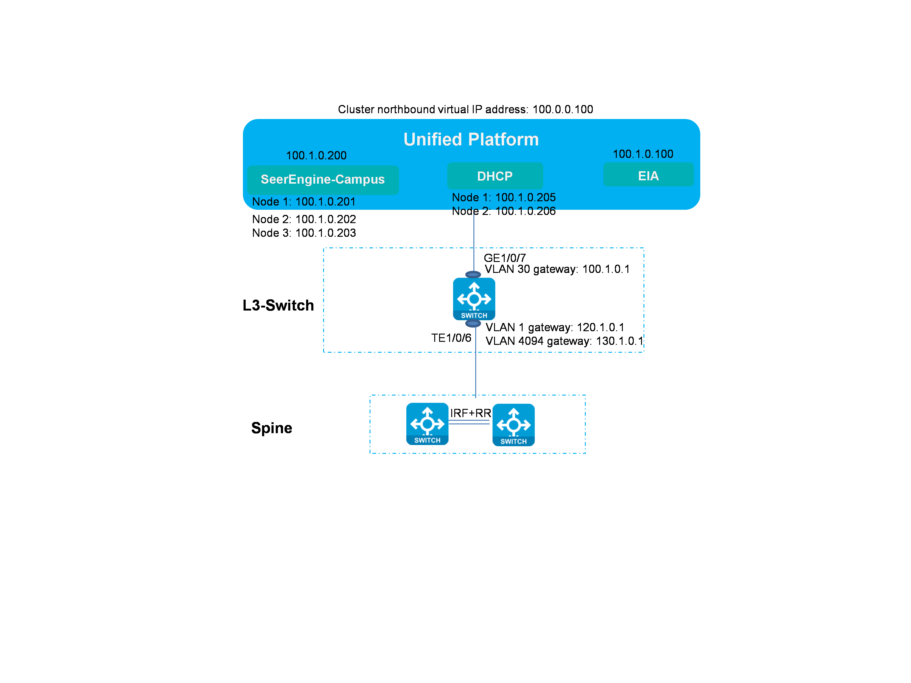
Table 6 Server IP addresses
|
Item |
Example |
Remarks |
|
VLAN 1 network segment (gateway) |
120.1.0.0/24 (120.1.0.1) |
VLAN 1 network for automated deployment |
|
VLAN 4094 network segment (gateway) |
130.1.0.0/24 (130.1.0.1) |
VLAN 4094 network for communication between the controller and devices |
|
VLAN 30 network segment (gateway) |
100.1.0.0/24 (100.1.0.1) |
Network segment used by Unified Platform, SeerEngine-Campus, and vDHCP |
|
VLAN 91 network segment |
91.1.0.0/24 |
VLAN for communication between spine and leaf devices during manual incorporation |
|
Network segment of the Underlay IP address |
200.1.1.0/24 |
Network segment of the loopback interface IP addresses on spine and leaf devices |
|
Unified Platform northbound service IP address |
100.1.0.100 |
The address used for logging in to Unified Platform |
|
EIA |
100.1.0.100 |
The northbound service IP of Unified Platform used by EIA server during converged deployment |
|
SeerEngine-Campus cluster IP address |
100.1.0.200 |
SeerEngine-Campus cluster IP address |
|
SeerEngine-Campus node IP addresses |
Node 1: 100.1.0.201 Node 2: 100.1.0.202 Node 3: 100.1.0.203 |
SeerEngine-Campus node IP addresses |
|
vDHCP cluster IP address |
100.1.0.204 |
Cluster IP address of the vDHCP server (not used actually) |
|
vDHCP node IP addresses |
Node 1: 100.1.0.205 Node 2: 100.1.0.206 |
IP addresses of the two nodes in the vDHCP server |
|
IP address of Microsoft DHCP |
8.0.1.171 |
IP address of the Microsoft DHCP server |
The SeerEngine-Campus controller and Unified Platform use different network adapters
The SeerEngine-Campus controller and Unified Platform can each use one NIC respectively and IP addresses in two network segments. In this case, EIA and Unified Platform cluster use the IP address in one network segment, while the SeerEngine-Campus and vDHCP use the IP address in the other one.
Figure 14 The SeerEngine-Campus controller and Unified Platform use different network adapters
In this example, the SeerEngine-Campus controller and Unified Platform each use one NIC respectively. Table 7 shows the address planning.
|
Item |
Example |
Remarks |
|
VLAN 1 network segment (gateway) |
120.1.0.0/24 (120.1.0.1) |
VLAN 1 network for automated deployment |
|
VLAN 4094 network segment (gateway) |
130.1.0.0/24 (130.1.0.1) |
VLAN 4094 network for communication between the controller and devices |
|
VLAN 30 network segment (gateway) |
100.1.0.0/24 (100.1.0.1) |
Network segment used by Unified Platform for communication with PCs |
|
VLAN 1010 network segment (gateway) |
110.1.0.0/24 (110.1.0.1) |
Network segment used by SeerEngine-Campus and vDHCP for communication between the controller and PCs (configured when SeerEngine-Campus uses an independent network adapter) |
|
VLAN 91 network segment |
91.1.0.0/24 |
VLAN for communication between spine and leaf devices when manually incorporating |
|
Network segment of the Underlay IP address |
200.1.1.0/24 201.1.1.0/24 |
Network segment of the loopback interface IP addresses on spine and leaf devices |
|
Unified Platform northbound service IP address |
100.1.0.100 |
The address used for logging in to Unified Platform |
|
EIA |
100.1.0.100 |
IP address of the EIA server |
|
SeerEngine-Campus cluster IP address |
110.1.0.100 |
SeerEngine-Campus cluster IP address |
|
SeerEngine-Campus node IP address |
Node 1: 110.1.0.101 Node 2: 110.1.0.102 Node 3: 110.1.0.103 |
SeerEngine-Campus node IP addresses |
|
vDHCP cluster IP address |
110.1.0.104 |
Cluster IP address of the vDHCP server (not used actually) |
|
vDHCP node IP address |
Node 1: 110.1.0.105 Node 2: 110.1.0.106 |
IP addresses of the two nodes in the vDHCP server |
|
IP address of Microsoft DHCP |
8.0.1.171 |
IP address of the Microsoft DHCP server |
User resource planning
Table 8 shows the resource planning of user services in this document.
Table 8 Resource planning of user services
|
Item |
Example |
Remarks |
|
Network segment of teacher security group (gateway) |
20.0.0.0/16 (20.0.0.1) |
Network for teacher security group users |
|
Network segment of student security group (gateway) |
30.0.0.0/16 (30.0.0.1) |
Network for student security group users |
|
Network segment of BYOD security group (gateway) |
50.0.0.0/16 (50.0.0.1) |
Network for BYOD users |
|
Guest network segment (gateway) |
22.2.2.0/24 (22.2.2.1) |
Network for guest users |
|
Authentication failure network segment (gateway) |
33.3.3.0/24 (33.3.3.1) |
Network for users who fail the authentication |
|
Fail-permit network segment (gateway) |
52.0.0.0/24 (52.0.0.1) |
Network for fail-permit users |
|
IP address group of Web Portal scenario |
104.0.0.1 to 104.0.0.254 |
Network segment that Web Portal connects to the users |
|
IT resource group |
41.0.0.0/8 |
IT resource group |
|
Campus egress address pool |
192.168.10.10 to 192.168.10.100 |
Campus egress address pool |
|
Microsoft tightly coupled DHCP address |
8.0.0.171 |
Microsoft tightly coupled DHCP address |
|
Microsoft loosely coupled DHCP address |
8.0.0.173 |
Microsoft loosely coupled DHCP address |
|
Third-party AAA address in the Web Portal scenario |
10.99.12.189 |
Third-party AAA address in the Web Portal scenario |
|
EIA address in the Web Portal scenario |
110.0.0.100 |
EIA address in the Web Portal scenario that can use a separate EIA. This section uses a separate EIA as a Web Portal server. |
|
IP address of the 4094 network segment of leaf device in the Web Portal scenario |
130.1.0.34 |
IP address of the 4094 network segment of leaf device in the Web Portal scenario |
User VLAN planning
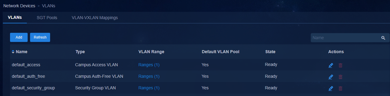
The SeerEngine-Campus presets four VLAN pools. Select Automation > Campus Network > Network Devices. Click the VNID Pools link in the upper right corner to open the VNID pool configuration page. Click the VLANs tab to open the VLAN pool page where you can view all the current VLAN pool information of the system.
The security group types are as follows. You cannot edit the resource pool names of the Campus access VLAN pool (default_access), the security group VLAN pool (default_security_group), and the campus authentication-free VLAN pool (default_auth_free) created by default.
|
|
IMPORTANT: · VLAN pools are not allowed to be modified after they are specified in a binding. To edit VLAN pools, for example, add or delete new VLAN ranges and reserve VLAN ranges, users need to plan ahead. · Different VLAN pools cannot overlap. · Access VLAN pools support the configuration of reserved VLAN ranges. · The SeerEngine-Campus assigns VLAN 100 by default for BFD detection of device automation stack. VLANs 4090 to 4094 are reserved VLANs. · When DRNI is configured, the controller issues VLAN 2 by default for the route synchronization of underlay between the two devices of the DR system. · If the user environment is upgraded from the previous version to the 6.0 version, VLAN audit differences might exist. You can resolve this issue through data synchronization. |
· Campus access VLAN pool: It is used to issue the VLAN configuration for access devices after they come online. The default VLAN range is 101 to 3000.
· Security group VLAN pool: It is used to assign VLAN IDs to security groups in isolated domains to enable user access. The default VLAN range is 3501 to 4000.
· Campus authentication-free VLAN pool: It is used to assign authentication-free VLAN IDs in isolated domains and to issue VLAN configurations on access devices in authentication-free bindings. The default VLAN range is 4051 to 4060.
· Campus static Access VLAN pool: You are recommended to use the VLAN range of 2801 to 3000 for static campus access VLANs. The range of the access VLAN pool needs to be modified to VLAN 101 to VLAN 2800. Configure the value according to the actual networking requirements.
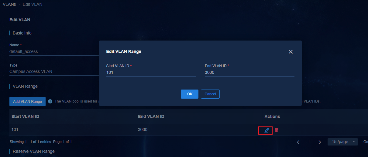
If you need to adjust the VLAN pool range
of each resource, click ![]() in the Actions
column as shown in the figure to open the page for editing the VLAN pool. In
the VLAN Range area, click
in the Actions
column as shown in the figure to open the page for editing the VLAN pool. In
the VLAN Range area, click ![]() in the Actions
column to open the Edit VLAN Range page and modify the VLAN range as
planned.
in the Actions
column to open the Edit VLAN Range page and modify the VLAN range as
planned.
AD-Campus configuration
Log in to the AD-Campus configuration page
1. After installation and deployment, enter the login address of the AD-Campus controller in the browser address bar to open the login page as shown in the following figure. The login address format is http://100.1.0.100:30000/. The login IP address is the northbound service IP of the Unified Platform cluster. The default login username and password are admin and Pwd@12345, respectively.
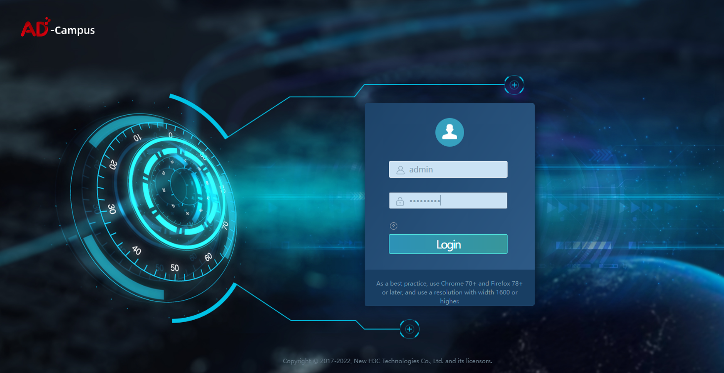
2. After entering the username and password, click Login to open the configuration page for the AD-Campus controller.
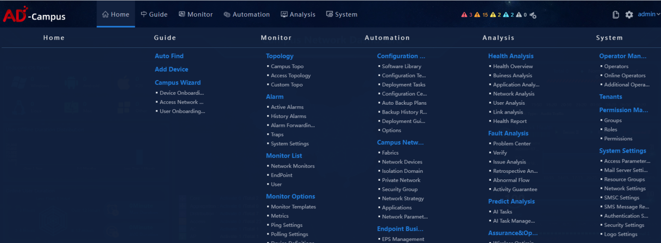
3. Click ![]() on the top left of the page to view all menus as follows:
on the top left of the page to view all menus as follows:
4. The automation function module is used to configure the AD-Campus services. Click the Automation tab on the page to expand the menu in the left navigation pane as follows:
¡ Configuration Options: You can configure services such as device backup, configuration recovery, and software libraries.
¡ Campus Network: You can configure services related to the SeerEngine-Campus controller, including automation template creation for device onboarding, isolation domain, fabric, security group, inter-group user policy, and service chain.
¡ User: You can configure services of the EIA authentication server, including access services, access policies, and access users.

Register licenses
|
|
NOTE: · After the controller installation and deployment, you need to register licenses for the convergence of SeerEngine-Campus, EIA, vDHCP, and Unified Platform. Before registering a license, configure a license server and purchase the license. · In the current software version, you can register a license or use a temporary license. · This section only introduces how to register a license on the AD-Campus interface. For the configuration of the license server, see the license server documentation. |
1. Select System > License> License Information to open the license registration page.
2. After the system is installed and deployed, a temporary license is available by default.
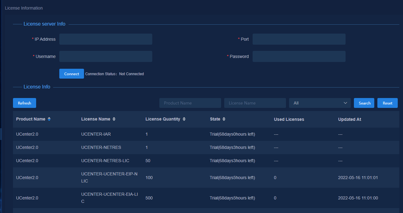
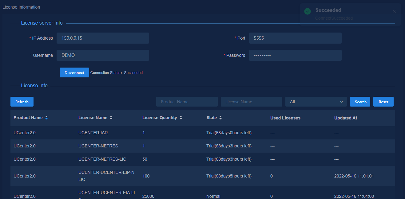
3. Configure the following license server parameters on the License Information page. Then click Connect to connect the license server.
¡ IP Address: Enter the IP address of the license server. Make sure the northbound IP of Unified Platform cluster and the license server can reach each other.
¡ Port: 5555.
¡ Username/Password: Enter username admin and password admin@123. The account and password are configured on the client configuration page. Enter the account and password as configured.
4. After the license registration, the license information page displays the licenses.
Prerequisites
Before using the configuration guide to configure services, you need to configure endpoint settings, system parameters, authentication server settings, and DHCP server settings.
Configure user endpoint settings
Perform the following tasks to enable VXLAN networking on the authentication server:
1. Navigate to the Automation > User > Access Parameters > System Settings page.
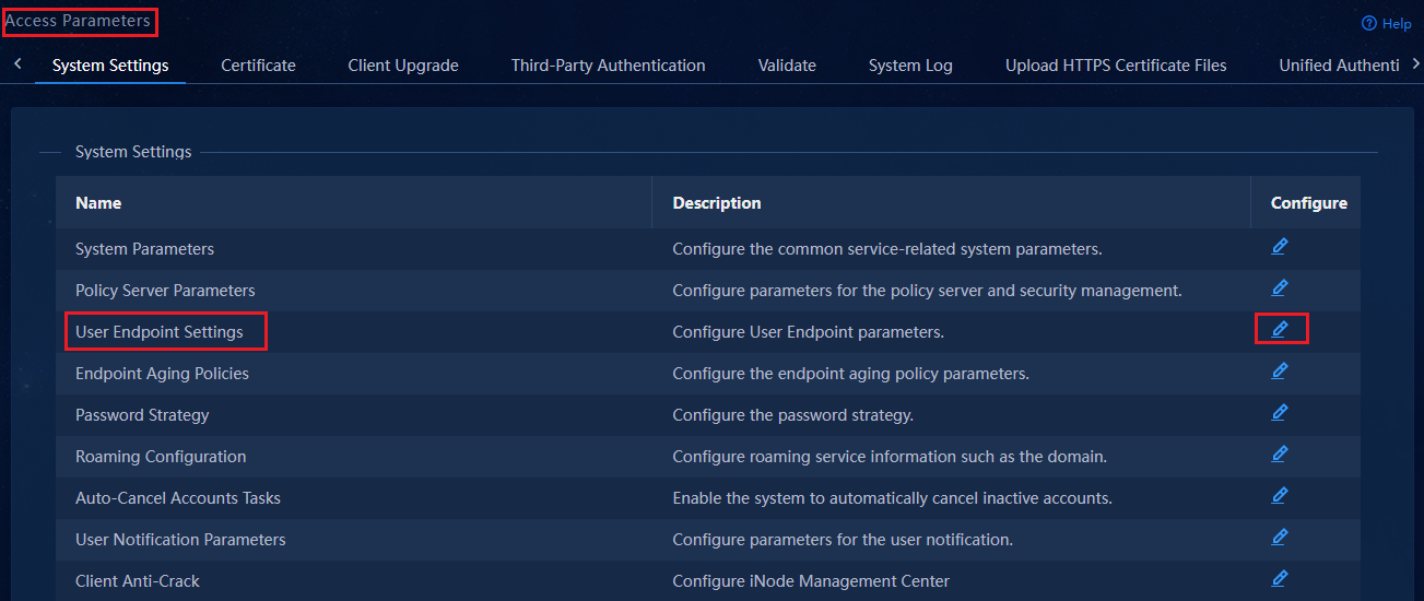
2. Click ![]() in the configure
column for User Endpoint Settings in the list to open the User
Endpoint Settings page. Configure the parameters of the User Endpoint
Settings and Director Controller Configuration.
in the configure
column for User Endpoint Settings in the list to open the User
Endpoint Settings page. Configure the parameters of the User Endpoint
Settings and Director Controller Configuration.
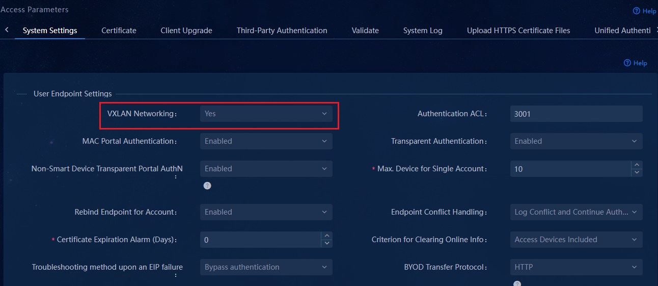
Parameters for user endpoint settings:
¡ VXLAN Networking: Select Yes.
¡ MAC Portal Authentication: Select Enabled.
¡ Transparent Authentication: Select Enabled.
¡ Forcibly unbind the IP address for accounts with the same name. The default setting is No.
- No: Selecting No indicates that the IP address is not preempted and the generated IP binding will not be reused.
- Yes: Selecting Yes indicates that the IP binding can preempt the IP address. When an endpoint bound to the IP address goes offline, another endpoint will reuse the IP binding of the offline endpoint when they come online.
¡ The maximum number of endpoints per account is used to limit the maximum number of authentication endpoints that an account can support. The default number is 10. For example, if you set the Max. Device for Single Account to 10, a maximum of 10 endpoints can use the account to come online upon authentication.
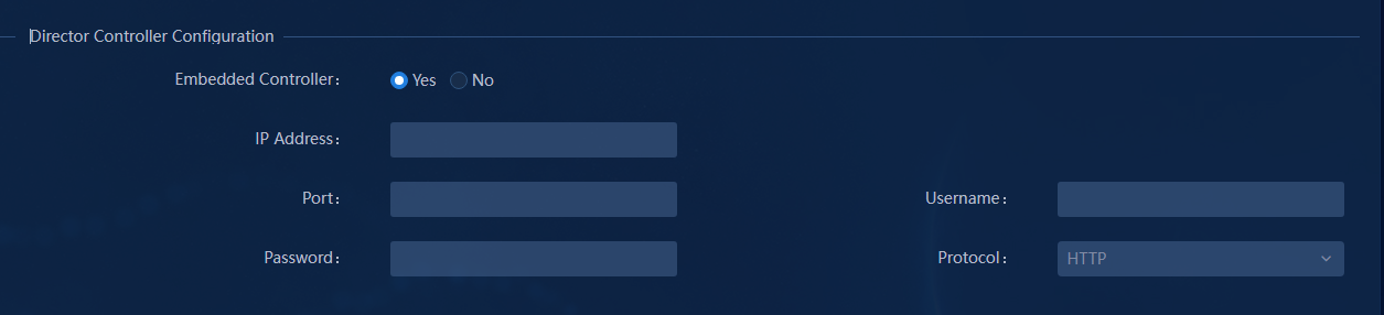
Parameters for the director controller configuration:
¡ Embedded Controller: If SeerEngine-Campus and EIA are deployed on the same platform, selecting Yes indicates that you do not need to manually specify the parameters. Selecting No indicates that you need to specify the following parameters.
¡ IP Address: Enter the IP address used to log in to the SeerEngine-Campus controller.
¡ Port: 30000 (port number for logging in to Unified Platform).
¡ Username/Password: Enter the default settings admin and Pwd@12345, respectively.
¡ Protocol: HTTP (or HTTPS). The default protocol is HTTP. Select the protocol used during Unified Platform deployment.
AAA
The AAA server supports H3C EIA V7 (iMC EIA), EIA V9 (containerized EIA), and third-party authentication servers.
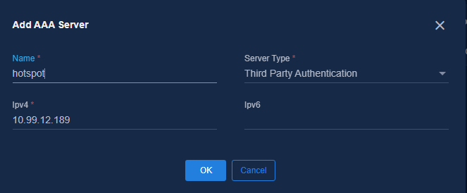
Navigate to the Automation > Campus Network > Network Parameters > AAA page, and click Add to add the EIA server.
· Name: Enter a name for the AAA server, which cannot be the same as the name of an existing AAA server in the current environment.
· Server Type: Select a server type.
¡ EIA V9: EIA server deployed on Unified Platform.
¡ EIA V7: EIA server deployed on the iMC platform. Only EIA V7 supports hierarchical EIA.
¡ Third-Party Authentication: Third party AAA server.
· Protocol: Select the protocol used to log in to the EIA server. The default setting is HTTP.
· IPv4 Address: Enter the IP address of the EIA server.
· IPv6 Address: Enter the IPv6 address of the EIA server. This parameter is optional.
· GUI Port: Automatically populated by the system based on the selected server type.
· User Name: Enter the username used to log in to the EIA server.
· Password: Enter the password used to log in to the EIA server.

EIA V9
After the EIA component is configured in Unified Platform cluster environment, EIA V9 containerized deployment automatically adds the EIA component to the AAA list as Default EIA.
EIA V7
An EIA V7 server is deployed on Windows or Linux operating system (iMC platform) and supports single-host mode, cluster mode, and hierarchical deployment mode.
· Single-host mode: Requires a physical server or a VM that supports a Windows or Linux operating system.
· Cluster mode: Requires two physical servers that use Windows or Linux operating systems. The two servers form a cluster.
· Hierarchical deployment mode: Requires one higher-level EIA node and multiple lower-level EIA nodes. A maximum of 20 nodes are supported. Authentication settings including users and policies are configured on the higher-level EIA node. The lower-level EIA nodes synchronize the settings from the higher-level node. This mode is suitable for multi-campus scenarios. These EIA nodes act as backups for each other to improve service availability. Only EIA V7 supports hierarchical EIA deployment. EIA V9 does not support hierarchical EIA deployment. In the current software version, only the Windows + MySQL or Linux + MySQL architecture is supported. The Windows + SQLServer is not supported. MySQL database versions 5.5 to 5.8 are supported. As a best practice, use version 5.7.
Third-party authentication
A third-party authentication server is used for Web Portal authentication. You only need to configure the IP address of the third-party server on the SeerEngine-Campus controller and make sure they can reach each other.
DHCP server
Navigate to the Automation > Campus Network > Network Parameters > DHCP page.
Click Add to open the Add DHCP Server page.
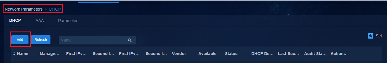
On the Add DHCP Server page, two management modes are available: tight coupling and loose coupling.
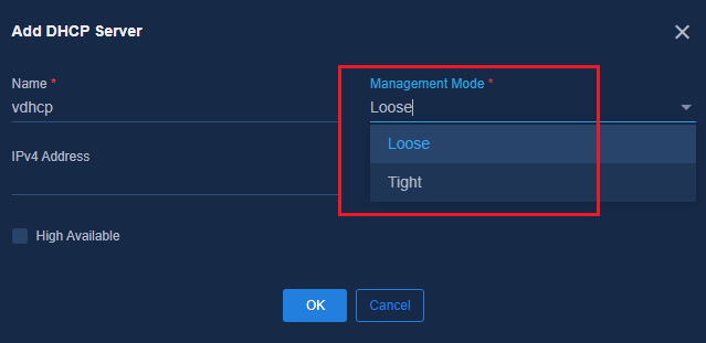
Tight coupling
|
|
NOTE: · H3C self-developed vDHCP servers and Microsoft DHCP servers support tight coupling. · In tight coupling mode, the SeerEngine-Campus controller requests creating an IP address pool with the DHCP server according to the IP address segment configured on the page. IP address binding is supported. · The DHCP server for automated device deployment must be an H3C vDHCP server. |
vDHCP server
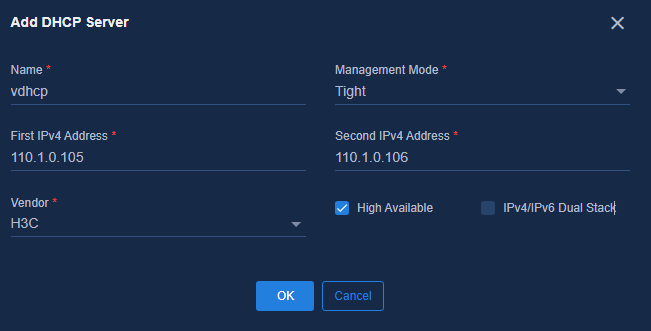
1. On the Add DHCP Server page, specify the following parameters and click OK to complete the configuration.
¡ Management Mode: Select Tight because vDHCP server only supports this mode.
¡ High Available: It is necessary to select it for a cluster environment and unnecessary for a standalone environment.
¡ IPv4/IPv6 Dual Stack: Enable dual-stack devices for IPv6 automation services or user IPv6 services. For configuration, see AD-Campus 6.2 IPv6 Service Configuration Guide.
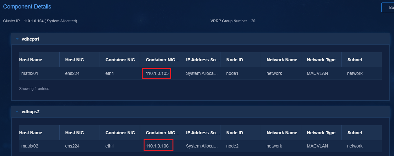
¡ IP
Address: Enter the IP addresses assigned during
vDHCP deployment. You can view
the IP addresses on the vDHCP deployment page. Navigate to the System
> Deployment Management, expand the Public Service option, and
click ![]() to view the details.
to view the details.
¡ Vendor: Select H3C.
2. After adding the DHCP server, click ![]() in
the Actions column for the DHCP server to synchronize the DHCP server.
The Audit Status column displays Audit Successful after the
synchronization is completed.
in
the Actions column for the DHCP server to synchronize the DHCP server.
The Audit Status column displays Audit Successful after the
synchronization is completed.
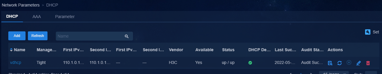
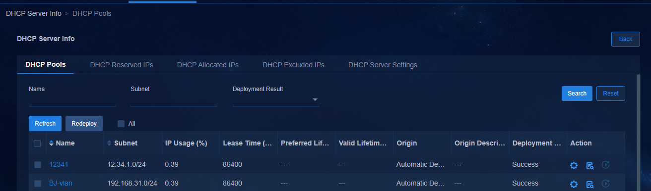
3. To view the address pool and IP address allocation information for the DHCP server, click the name of the DHCP server.
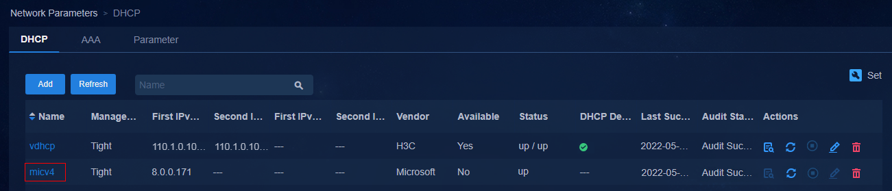
Add a Microsoft DHCP server
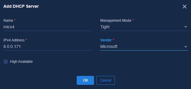
1. Add a DHCP server
a. On the Add DHCP Server page, select Microsoft for Vendor, configure the following parameters, and then click OK.
- Management Mode: Select Tight.
- High Available: Select this option in DHCP HA mode. In standalone mode, you do not need to select this option.
- IPv4: Enter the IP address of the Microsoft DHCP server. In cluster mode, enter the IP addresses of both DHCP servers.
- Vendor: Select Microsoft.
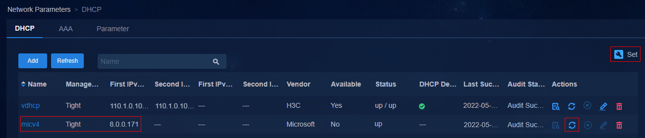
b. After adding the DHCP server, click ![]() in
the Actions column for the DHCP server to synchronize the DHCP server.
The Audit Status column displays Audit Successful after the
synchronization is completed.
in
the Actions column for the DHCP server to synchronize the DHCP server.
The Audit Status column displays Audit Successful after the
synchronization is completed.
c. To monitor Microsoft DHCP HA status, click ![]() in the upper
right corner of the DHCP list page. By default, HA monitor is enabled. The
SeerEngine-Campus controller monitors DHCP HA status periodically. The
controller automatically enables the backup Microsoft DHCP server when it
detects failure of the primary Microsoft DHCP server.
in the upper
right corner of the DHCP list page. By default, HA monitor is enabled. The
SeerEngine-Campus controller monitors DHCP HA status periodically. The
controller automatically enables the backup Microsoft DHCP server when it
detects failure of the primary Microsoft DHCP server.
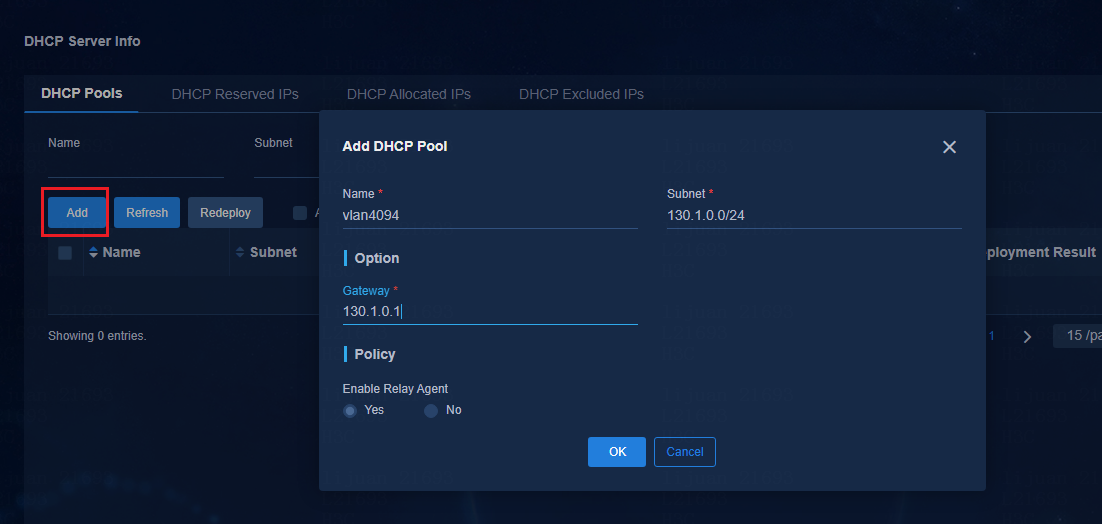
2. Configure the VXLAN 4094 address pool.
|
|
IMPORTANT: After adding a Microsoft DHCP server, you must manually create an address pool on the SeerEngine-Campus controller, and make sure the address pool is on the same network as VXLAN 4094 on the device. If you do not create an address pool, the Microsoft DHCP server cannot respond to the DHCP requests sent by leaf devices. |
On the DHCP tab, click the name of the Microsoft DHCP server.
On the DHCP Pools tab, click Add to add an address pool.
¡ Subnet: Make sure the address pool is on the same network as VXLAN 4094 on the device. This address pool is not used for user services.
¡ Gateway: Enter an IP address in the same network segment as VXLAN 4094.
¡ For the other parameters, use the default values.
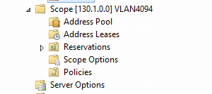
After the Microsoft DHCP server is created and deployed successfully, you can see the created scope on the Microsoft DHCP server.
Loose coupling
|
|
NOTE: · Microsoft DHCP servers and WRD DHCP servers (supporting Option 82) support loose coupling. · In loose coupling mode, the SeerEngine-Campus controller does not create any address pools on the DHCP server or synchronize address pool information from the DHCP server. · You must manually create all address pools and policies in the address pools for matching Option 82 information carried in DHCP relay packets sent by leaf devices. |
A DHCP server in loose coupling mode cannot
be synchronized. No ![]() button is available for the
DHCP server and the Audit Status is "--".
button is available for the
DHCP server and the Audit Status is "--".
In loose coupling mode, the SeerEngine-Campus controller does not issue any configuration to the DHCP server or synchronize the address pool information of the DHCP server. Therefore, you need to manually create the address pool of subnets in the fail-permit security group and the address pool policy on the DHCP server.
The address pool policy configuration requires the third-party DHCP server to set the VXLAN ID to the Option 82 value and identify Option 82 in DHCP packets. The configuration methods vary by DHCP server. For more information, see the configuration information of each DHCP server vendor.

Conversational forwarding entry learning for static ACs
If S6520X series or S5560X series devices exist in the network, as a best practice, navigate to the Automation > Campus Network > Network Parameters > Parameters page to enable conversational forwarding entry learning for static ACs.
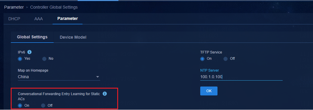
After you enable the function, only when the service instance receives service traffic, the device issues the forwarding entry information of the service instance to the driver to make the configuration take effect. Deploy the following settings for the static service instance on the leaf device:
#
interface Bridge-Aggregation1024
port link-type trunk
port trunk permit vlan 1 101 to 3000 4093 to 4094
link-aggregation mode dynamic
stp tc-restriction
mac-based ac
dot1x
undo dot1x multicast-trigger
dot1x unicast-trigger
dot1x critical vsi vsi9
dot1x critical eapol
mac-authentication
mac-authentication hz1
port-security free-vlan 1 3501 to 3505 4094
#
service-instance 3501
encapsulation s-vid 3501
xconnect vsi vsi3 on-demand
arp detection trust
#
Device onboarding
Legacy automated device onboarding
Legacy automated device onboarding is the process of the controller and devices implementing the automation. For detailed configuration, see AD-Campus 6.2 Automation Configuration Guide.
Optimized automated device onboarding
Optimized automated device onboarding enables the controller to implement the automation without support of devices. For detailed configuration, see AD-Campus 6.2 Optimized Automation Configuration Guide.
Semi-automation onboarding
Semi-automation onboarding is the manual incorporation of spine and leaf devices. For the scenario of automated access device onboarding and manual incorporation of spine and leaf devices, see "Manually incorporate a device." For automated access device onboarding and other semi-automation configuration, see AD-Campus 6.2 Semi-Automation Configuration Guide.
Manually incorporate a device
This section describes the basic configuration procedures for manual configuration of spine devices, leaf devices, and access devices that are not automatically deployed. The following configuration is based only on the underlay configuration by device role, and the configuration required by the controller to incorporate the device. After the configuration, the SeerEngine-Campus controller can incorporate the device.
|
|
IMPORTANT: · The document describes the underlay manual configuration. For the underlay automation configuration, see AD-Campus 6.2 Automation Configuration Guide. · When the gateway without an L3 Switch or VLAN 4094 segment is on a spine device, you do not need to configure static routes to the controller network segment on leaf devices. |
Configure the Layer 3 switch
To configure a Layer 3 switch:
1. Enable DHCP and STP globally.
# Enable DHCP.
dhcp enable
#
# Enable STP.
stp global enable
#
Configure the VLAN 4094 interface.
#
Vlan 4094
#
#
interface Vlan-interface4094
ip address 130.1.0.1 255.255.255.0
#
# VLAN 1 configuration is used for automated device onboarding. If all devices in the network are manually onboarded, VLAN 1 configuration is not required.
interface Vlan-interface1
ip address 120.1.0.1 255.255.255.0
dhcp select relay //DHCP relay agent related configurations are used for automated device onboarding. If spine/leaf/access devices are manually configured and incorporated, DHCP relay agent related configurations are not required.
dhcp relay server-address 110.1.0.105 //IP address of the vDHCP server node.
dhcp relay server-address 110.1.0.106
#
Create VLAN interfaces for VLAN 30 and VLAN 1010.
#
Vlan 30
Vlan 1010
#
#
interface Vlan-interface 30
ip address 100.1.0.1 255.255.255.0
#
#
interface Vlan-interface 1010
ip address 110.1.0.1 255.255.255.0
#
Configure the interface connected to the spine device.
#
interface Ten-GigabitEthernet1/0/6
description to_spine
port link-type trunk
port trunk permit vlan 1 4094 //If spine/leaf/access devices are deployed and onboarded manually in the network, execute the undo permit vlan1 command.
#
Add the interface connecting to Unified Platform to VLAN 30.
#
interface GigabitEthernet1/0/7
port access vlan 30
stp edged-port //Specify the Layer 3 switch port connecting the server as STP edge port.
#
Add the interface connecting to SeerEngine-Campus and vDHCP to VLAN 1010.
#
interface GigabitEthernet1/0/3
port access vlan 1010
stp edged-port //Specify the Layer 3 switch port connecting the server as STP edge port.
#
Add the default route.
# Set its next hop to the IP address of the VSI-interface 4094 on the spine device for interconnection between authentication users and EIA.
ip route-static 0.0.0.0 0 130.1.0.2 //Configure a default route whose next hop is the interface address of VSI-interface 4094 on the spine device.
#
Configure spine devices
Before incorporating a Spine device into SeerEngine-Campus, manually perform the following operations:
1. Configure the spine role and sysname.
# For a device whose role is spine by default, you do not need to configure the spine role. Otherwise, configure its spine role first and restart the device for the configuration to take effect.
vcf-fabric role spine
#
sysname Spine
#
2. Configure LLDP to determine the topology.
#
lldp global enable
#
3. Configure STP.
#
stp ignored vlan 2 to 4094
stp global enable
stp root primary //Specify the spine device as the STP root.
#
4. Configure SNMP, NETCONF, Telnet, and SSH.
# Configure SNMP. The following provides the default configuration, and the SNMP community strings can be adjusted based on the actual configuration.
snmp-agent
snmp-agent community write private
snmp-agent community read public
snmp-agent sys-info version all
snmp-agent packet max-size 4096
#
# Configure NETCONF.
netconf soap http enable
netconf soap https enable
netconf ssh server enable
restful https enable
#
# Configure Telnet.
telnet server enable //Configure Telnet when using Telnet functions
#
# Configure SSH.
ssh server enable
#
5. Configure the username and password of Telnet and SSH.
# Set the username to admin and password to H3C1234567.
local-user admin class manage
password simple H3C1234567 //Make sure the password meets the complexity requirements. The password must be 10 to 63 characters in length and contains at least two types of the following characters: Digits, uppercase letters, lowercase letters, and special characters. Chinese characters are not supported and the password cannot contain the question mark (?), spaces, username, or username in reverse order.
service-type telnet http https ssh
authorization-attribute user-role network-admin
authorization-attribute user-role network-operator
#
#
line vty 0 63
authentication-mode scheme
user-role network-admin
user-role network-operator
#
6. Create VLAN 4094.
# Create VLAN 4094.
Vlan 4094
#
7. Configure OSPF.
#
ospf 1 router-id 200.1.1.254
non-stop-routing
area 0.0.0.0
#
8. Configure the loopback interface.
#
interface LoopBack0
ip address 200.1.1.254 255,255,255,255
ospf 1 area 0.0.0.0 //Configure OSPF.
#
9. Configure the downlink interface of the spine device. If multiple downlink interfaces exist, create multiple VLAN interfaces.
# Create a VLAN.
Vlan 91
#
# Create a VLAN interface.
interface Vlan-interface91
ip address 91.1.0.1 24 //Use an unused network address.
ospf network-type p2p
ospf 1 area 0.0.0.0
#
# Execute the port trunk permit command on the downlink interface of the spine device.
#
interface Ten-GigabitEthernet3/0/16
port link-mode bridge
port link-type trunk
port trunk permit vlan 1 91 //If spine/leaf/access devices are deployed and onboarded manually in the network, execute the undo permit vlan1 command.
#
By default, SeerEngine-Campus automatically assigns the following VLANs:
¡ VLAN 2 for route synchronization of Underlay between two devices for DRNI.
¡ VLAN 100 for BFD of automatic stacking devices.
¡ VLAN 101 to VLAN 2800 for access switches.
¡ VLAN 2801 to VLAN 3000 for static access to ACs.
¡ VLAN 3501 to VLAN 4000 for security groups.
¡ VLAN 3001 to VLAN 3500 for interconnection links between spine and leaf devices in automated onboarding.
¡ VLAN 4090 to VLAN 4094 are reserved.
¡ VLAN 1 to VLAN 99 and VLAN 4001 to VLAN 4089 are not automatically assigned by the controller.
¡ VLAN 4051 to VLAN 4060 are used as authentication-free VLANs by default.
¡ As a best practice, use VLAN 3 to VLAN 99, VLAN 4001 to VLAN 4050, and VLAN 4061 to VLAN 4089 when configuring VLAN interfaces for routing.
The multiple links between spine and leaf devices are ECMP links. It is normal if the link between spine and leaf devices is in the discarding state because STP is enabled for VLAN 1.
10. Enable L2VPN.
#
l2vpn enable
#
11. Configure VPN-Target, the IP addresses of VSI VXLAN 4094 and VSI interface, and L3VNI for the connectivity of the tunnel between the controller and the device.
# Create VPN-Default, and configure RDs and RTs to 1:1 globally.
#
ip vpn-instance vpn-default
route-distinguisher 1:1
vpn-target 1:1 import-extcommunity
vpn-target 1:1 export-extcommunity
#
address-family ipv4
vpn-target 1:1 import-extcommunity
vpn-target 1:1 export-extcommunity
#
address-family evpn
vpn-target 1:1 import-extcommunity
vpn-target 1:1 export-extcommunity
#
# Configure the IP address of VSI-interface 4094.
interface Vsi-interface4094
ip binding vpn-instance vpn-default
ip address 130.1.0.2 255.255.255.0
local-proxy-arp enable
arp proxy-send enable //Enable the ARP proxy to solve the problem that the endpoint device cannot connect to the server without the server ARP information due to a network exception or timeout.
#
# Configure a VSI interface and an L3VNI for Layer 3 forwarding.
# Use the ip address unnumbered command to enable the interface to borrow the IP address of a specific interface. When a security group is created for VPN-Default, the source IP address of the packet sent by Layer 3 forwarding is specified as the IP address of VSI-interface 4094.
# Create VSI-interface 4092 to configure the L3VNI of VPN-Default.
interface Vsi-interface4092
ip binding vpn-instance vpn-default
ip address unnumbered interface Vsi-interface4094
l3-vni 4092
#
# Configure the VSI VXLAN 4094 instance.
vsi vxlan4094
gateway vsi-interface 4094
vxlan 4094
evpn encapsulation vxlan
mac-advertising disable
arp mac-learning disable
nd mac-learning disable
route-distinguisher auto
vpn-target auto export-extcommunity
vpn-target auto import-extcommunity
#
12. Configure BGP EVPN.
# Configure BGP. If there are multiple leaf devices, configure multiple peers.
# The manually configured BGP AS number must be consistent with the AS number set in the fabric of SeerEngine-Campus.
#
bgp 100
non-stop-routing
router-id 200.1.1.254 //Each device has a different router ID.
peer 200.1.1.252 as-number 100 //Configure the BGP peer. The IP address of the BGP peer is the IP address of the loopback interface on the Leaf device.
peer 200.1.1.252 connect-interface LoopBack0
#
address-family l2vpn evpn
reflector cluster-id 200.1.1.254 //Configure the reflector cluster in the dual-spine environment. Two devices have the same cluster ID.
undo policy vpn-target //Configure the undo policy vpn-target and do not filter the received VPNv4 routes.
peer 200.1.1.252 enable //Configure multiple leaf entries if multiple leaf nodes exist.
peer 200.1.1.252 reflect-client //Configure a route reflector for forwarding routes between different Leaf devices.
#
ip vpn-instance vpn-default
#
address-family ipv4 unicast
import-route direct //Import direct routes if the on-demand deployment of IPv4 addresses is enabled on a leaf device.
import-route static //Import static routes.
#
13. Configure the uplink interface (connecting to the Layer 3 switch) of the spine device as the AC interface and bind it to VSI VXLAN 4094.
#
interface Ten-GigabitEthernet3/0/2
port link-mode bridge
port link-type trunk
port trunk permit vlan 1 4094 //If spine/leaf/access devices are deployed and onboarded manually in the network, execute the undo permit vlan1 command.
service-instance 4094 //Create service instance 4094.
encapsulation s-vid 4094 //Match VLAN tag 4094.
xconnect vsi vxlan4094 //Bind VSI VXLAN 4094.
#
14. Configure static routes.
# Configure a static route to the server with the IP address of VLAN 4094 of the Layer 3 switch as the next hop when the spine device is connected to SeerEngine-Campus and EIA at Layer 3.
ip route-static vpn-instance vpn-default 110.1.0.0 24 130.1.0.1 //The destination IP address is on the subnet of the controller.
#
ip route-static vpn-instance vpn-default 100.1.0.0 24 130.1.0.1 //The destination IP address is on the subnet of the server.
#
# If the DHCP server IP address is on another network, you need to add a static route to the DHCP server.
ip route-static vpn-instance vpn-default 132.0.0.0 24 130.1.0.1 //DHCP server network IP address.
#
15. Disable MAC address learning and ARP/ND learning of the VXLAN tunnel.
# Disable ARP learning of the VXLAN tunnel to prohibit ARP learning for remote packets.
vxlan tunnel arp-learning disable
#
# For configuring the IPv6 service, you need to disable ND learning.
vxlan tunnel nd-learning disable
#
# Disable MAC address learning of the VXLAN tunnel to prohibit MAC address learning for remote packets.
vxlan tunnel mac-learning disable
#
16. Configure NTP.
#
clock timezone beijing add 08:00:00
#
# The IP address is the IP address of the NTP server. Unified Platform is configured with a built-in NTP server. The IP address is cluster northbound service IP.
ntp-service enable
ntp-service unicast-server 100.1.0.100 vpn-instance vpn-default
#
17. Set the bridge MAC address in an unchanged state for an IRF fabric of spine devices. If the spine device is in an IRF fabric, use the following command to ensure that the bridge MAC address of the device remains unchanged during a master/backup switchover.
#
irf mac-address persistent always
#
Configure leaf devices
|
|
IMPORTANT: If an S5560X switch or S6520X switch is used as a leaf device, set the switch mode to VXLAN and restart the device for the configuration to take effect. |
Before incorporating a leaf device to SeerEngine-Campus, manually perform the following operations:
# View the switch mode and make sure it is VXLAN mode.
dis switch-mode status
Switch-mode in use: VXLAN MODE.
Switch-mode for next reboot: VXLAN MODE.
#
# Use the following command to view the switch mode.
switch-mode ?
0 NORMAL MODE (default)
1 VXLAN MODE
2 802.1BR MODE
3 MPLS MODE
4 MPLS-IRF MODE
#
# Set the mode to VXLAN mode, and then restart the device for the configuration to take effect.
switch-mode 1
#
1. Configure the leaf role and sysname.
# For a device whose role is leaf by default, you do not need to configure the leaf role. Otherwise, configure its leaf role first and restart the device for the configuration to take effect.
#vcf-fabric role leaf
#
# Configure sysname.
sysname leaf1
#
2. Configure LLDP to determine the topology.
#
lldp global enable
#
3. Configure STP.
#
stp ignored vlan 2 to 4094
stp global enable
#
4. Execute the stp tc-restriction command on the downlink interface of the Leaf device.
int Ten-GigabitEthernet1/3/0/16
#
stp tc-restriction #
|
|
WARNING! Execute the stp tc-restriction command on the downlink interface of the leaf device. If it is directly connected to an endpoint device, execute the stp edged-port command. |
5. Configure SNMP, NETCONF, Telnet, and SSH.
# Configure SNMP. The following provides the default configuration, and the SNMP community strings can be adjusted based on the actual configuration.
snmp-agent
snmp-agent community write private
snmp-agent community read public
snmp-agent sys-info version all
snmp-agent packet max-size 4096
#
# Configure NETCONF.
#
netconf soap http enable
netconf soap https enable
netconf ssh server enable
restful https enable
#
# Configure Telnet.
telnet server enable
#
# Configure SSH.
ssh server enable
#
6. Configure the username and password of Telnet and SSH.
# Set the username to admin and password to H3C1234567.
local-user admin class manage
password simple H3C1234567 //Make sure the password meets the complexity requirements. The password must be 10 to 63 characters in length and contains at least two types of the following characters: Digits, uppercase letters, lowercase letters, and special characters. Chinese characters are not supported and the password cannot contain the question mark (?), spaces, username, or username in reverse order.
service-type telnet http https ssh
authorization-attribute user-role network-admin
authorization-attribute user-role network-operator
#
#
line vty 0 63
authentication-mode scheme
user-role network-admin
user-role network-operator
#
7. Create VLAN 4094.
# Create VLAN 4094.
Vlan 4094
#
8. Configure OSPF.
#
ospf 1 router-id 200.1.1.252
non-stop-routing
area 0.0.0.0
#
9. Configure the loopback interface.
#
interface LoopBack0
ip address 200.1.1.252 255.255.255.255 // Establish a BGP peer with the spine device.
ospf 1 area 0.0.0.0
#
10. Configure an L3 VLAN interface for interconnection with the spine device.
# Create a VLAN.
vlan 91 // Make sure the VLAN is the same as the VLAN on the spine device.
#
# Create a VLAN interface.
interface Vlan-interface91
ip address 91.1.0.2 255.255.255.0
ospf network-type p2p
ospf 1 area 0.0.0.0
#
# Execute the port trunk permit vlan command on the uplink interface of the leaf device.
#
interface Ten-GigabitEthernet1/2/0/13
port link-mode bridge
port link-type trunk
port trunk permit vlan 1 91
#
By default, SeerEngine-Campus automatically assigns the following VLANs:
¡ VLAN 2 for route synchronization of Underlay between two devices for DRNI.
¡ VLAN 100 for BFD of automated stacking devices.
¡ VLAN 101 to VLAN 2800 for access switches.
¡ VLAN 2801 to VLAN 3000 for static connections to ACs.
¡ VLAN 3501 to VLAN 4000 for security groups, VLAN 3001 to VLAN 3500 for interconnection links between spine and leaf devices in automated onboarding.
¡ VLAN 4090 to VLAN 4094 are reserved.
¡ VLAN 3 to VLAN 99 and VLAN 4001 to VLAN 4089 are not automatically assigned by the controller.
¡ VLAN 4051 to VLAN 4060 are used as authentication-free VLANs by default.
¡ As a best practice, use VLAN 3 to VLAN 99, VLAN 4001 to VLAN 4050, and VLAN 4061 to VLAN 4089 when configuring VLAN interfaces for routing.
The multiple links between spine and leaf devices are ECMP links. It is normal if the link between spine and leaf devices is in a discarding state because STP is enabled for VLAN 1.
11. Enable L2VPN.
# Enable L2VPN.
l2vpn enable
#
12. Configure VPN-Default, the IP addresses of VSI VXLAN 4094 and VSI interface, and L3VNI, and configure the service instance (binding VXLAN 4094) on the downlink AC interface (connecting to access devices) for the connectivity of the tunnel between the controller and the device.
# Create VPN-Default, and manually configure RDs and RTs to 1:1 globally.
#
ip vpn-instance vpn-default
route-distinguisher 1:1
vpn-target 1:1 import-extcommunity
vpn-target 1:1 export-extcommunity
#
address-family ipv4
vpn-target 1:1 import-extcommunity
vpn-target 1:1 export-extcommunity
#
address-family evpn
vpn-target 1:1 import-extcommunity
vpn-target 1:1 export-extcommunity
#
# Configure the IP address of VSI-interface 4094.
#
interface Vsi-interface4094
ip binding vpn-instance vpn-default
ip address 130.1.0.3 255.255.255.0
local-proxy-arp enable
arp proxy-send enable //Enable the ARP proxy to solve the problem that the endpoint device cannot connect to the server without ARP information on the server due to a network exception or timeout.
#
# Configure a VSI interface and an L3VNI for Layer 3 forwarding.
# Use the ip address unnumbered command to enable the interface to borrow the IP address of a specific interface. When a security group is created for VPN-Default, the source IP address of the packet sent by Layer 3 forwarding is specified as the IP address of VSI-interface 4094.
#
interface Vsi-interface4092
ip binding vpn-instance vpn-default
ip address unnumbered interface Vsi-interface4094
l3-vni 4092
#
# Configure the VSI VXLAN 4094 instance.
#
vsi vxlan4094
gateway vsi-interface 4094
vxlan 4094
evpn encapsulation vxlan
mac-advertising disable
arp mac-learning disable
route-distinguisher auto
vpn-target auto export-extcommunity
vpn-target auto import-extcommunity
dhcp snooping trust tunnel
#
# Configure the downlink interface of the leaf device connecting to the access device as an AC interface.
interface Ten-GigabitEthernet1/2/0/9
port link-mode bridge
port link-type trunk
port trunk permit vlan 1 4094
stp tc-restriction
#
service-instance 4094
encapsulation s-vid 4094
xconnect vsi vxlan4094
#
13. Configure BGP EVPN.
# Configure BGP 100 and specify a spine device as a BGP peer.
#
bgp 100
non-stop-routing
router-id 200.1.1.252 // Each device has a different router ID. As a best practice, configure the ID as the IP address of the loopback interface.
Peer 200.1.1.254 as-number 100
peer 200.1.1.254 connect-interface LoopBack0
#
address-family l2vpn evpn
peer 200.1.1.254 enable
#
ip vpn-instance vpn-default
#
address-family ipv4 unicast
#
14. Configure static routes.
# Configure a static route to the server with the IP address of VLAN 4094 of the Layer 3 switch as the next hop when the spine device and server are connected at Layer 3.
ip route-static vpn-instance vpn-default 110.1.0.0 24 130.1.0.1 //The destination IP address is on the subnet of the controller.
#
ip route-static vpn-instance vpn-default 100.1.0.0 24 130.1.0.1 //The destination IP address is on the subnet of the server.
#
# If the DHCP server is on another network, you need to add a static route to the DHCP server.
ip route-static vpn-instance vpn-default 132.0.0.0 24 130.1.0.1 //DHCP server network IP address.
#
15. Configure DHCP snooping.
#
dhcp snooping enable vlan 2 to 4094
#
16. Configure the IP source guard as filter-free for VLAN 1 and VLAN 4094.
# The configuration is required when IP source guard is configured for the leaf downlink interface. The service is not affected when IP source guard is not configured.
ip verify source exclude vlan 1
ip verify source exclude vlan 4094
#
17. Disable MAC address learning and ARP learning of the VXLAN tunnel.
# Disable ARP learning of the VXLAN tunnel.
vxlan tunnel arp-learning disable
#
# Disable MAC address learning of the VXLAN tunnel.
vxlan tunnel mac-learning disable
#
18. Enable conversational learning. (This function is optional and disabled by default. You can enable it as required.)
If conversational learning is enabled on the leaf device, you need to import direct routes for BGP vpn-default on the spine device. This operation imports all private subnet routes of the endpoints to leaf and spine devices, ensuring interoperability between the endpoints and the server and the external networks.
# To save hardware resources, the remote ARP entries synchronized through EVPN are not delivered to hardware by default, but delivered in case of traffic requests.
ip forwarding-conversational-learning //Enable conversational learning.
# After the traffic is stopped, the default aging time for deleting hardware table entries is 60 minutes. You can use the following command to set the aging time.
[leaf1]ip forwarding-conversational-learning aging ?
INTEGER<60-1440> Aging time in (minutes)
#
|
|
IMPORTANT: · As a best practice, configure the on-demand deployment function for S5560X-HI and S6520X-HI. · As a best practice, do not configure the on-demand deployment function if a leaf device acts as a border device at the same time. |
19. Configure NTP.
#
clock timezone beijing add 08:00:00
#
# Specify the IP address of the NTP server.
ntp-service enable
ntp-service unicast-server 100.1.0.100 vpn-instance vpn-default
#
20. Verify the configuration.
After finishing the above configuration tasks, check whether those tasks are successfully configured. The following information can be viewed from both the spine and leaf devices:
[leaf1] display interface Vsi-interface brief
Brief information on interfaces in route mode:
Link: ADM - administratively down; Stby - standby
Protocol: (s) - spoofing
Interface Link Protocol Primary IP Description
Vsi4092 UP UP 130.1.0.3 //VSI-interfaces 4094 and 4092 are created successfully.
Vsi4094 UP UP 130.1.0.3
[leaf1]
[leaf1]dis l2vpn vsi
Total number of VSIs: 2, 1 up, 1 down, 0 admin down
VSI Name VSI Index MTU State
Auto_L3VNI4092_4092 0 1500 Down //Automatically generated.
vxlan4094 1 1500 Up
[leaf1]
[leaf1] display interface Tunnel brief
Brief information on interfaces in route mode:
Link: ADM - administratively down; Stby - standby
Protocol: (s) - spoofing
Interface Link Protocol Primary IP Description
Tun1 UP UP -- //Tunnel is up.
[leaf1]
[leaf1] display interface Tunnel
Tunnel1
Current state: UP
Line protocol state: UP
Description: Tunnel1 Interface
Bandwidth: 64 kbps
Maximum transmission unit: 1464
Internet protocol processing: Disabled
Last clearing of counters: Never
Tunnel source 200.1.1.252, destination 200.1.1.254
Tunnel protocol/transport UDP_VXLAN/IP
Last 300 seconds input rate: 0 bytes/sec, 0 bits/sec, 0 packets/sec
Last 300 seconds output rate: 0 bytes/sec, 0 bits/sec, 0 packets/sec
Input: 29 packets, 2064 bytes, 0 drops
Output: 8 packets, 720 bytes, 0 drops
[leaf1]
[leaf1]ping -vpn-instance vpn-default 100.1.0.100 //Ping the server.
Ping 100.1.0.100 (100.1.0.100): 56 data bytes, press CTRL+C to break
56 bytes from 100.1.0.100: icmp_seq=0 ttl=63 time=3.646 ms
56 bytes from 100.1.0.100: icmp_seq=1 ttl=63 time=1.699 ms
56 bytes from 100.1.0.100: icmp_seq=2 ttl=63 time=2.058 ms
56 bytes from 100.1.0.100: icmp_seq=3 ttl=63 time=7.078 ms
56 bytes from 100.1.0.100: icmp_seq=4 ttl=63 time=1.680 ms
--- Ping statistics for 100.1.0.100 in VPN instance vpn-default ---
5 packet(s) transmitted, 5 packet(s) received, 0.0% packet loss
round-trip min/avg/max/std-dev = 1.483/1.620/1.991/0.189 ms
[leaf1]
21. Set the bridge MAC address in an unchanged state for a leaf IRF fabric.
If the leaf device is in an IRF fabric, use the following command to ensure that the bridge MAC address of the device remains unchanged during a master/subordinate switchover.
#
irf mac-address persistent always
#
Configure access devices
1. Configure the access role and sysname of the device.
# The default role is access. The non-default role requires a reboot to take effect.
#
vcf-fabric role access
#
#
sysname access1
#
2. Configure LLDP to determine the topology.
#
lldp global enable
#
3. Configure STP.
#
stp global enable
#
4. Configure SNMP, NETCONF, Telnet, and SSH.
# Configure SNMP. The following provides the default configuration, and the SNMP community strings can be adjusted based on the actual configuration.
#
snmp-agent
snmp-agent community write private
snmp-agent community read public
snmp-agent sys-info version all
snmp-agent packet max-size 4096
#
# Configure NETCONF.
netconf soap http enable
netconf soap https enable
netconf ssh server enable
restful https enable
#
# Configure Telnet.
telnet server enable
#
# Configure SSH.
ssh server enable
#
5. Configure the username and password of Telnet and SSH.
# Set the username to admin and password to H3C1234567.
local-user admin class manage
password simple H3C1234567 //Make sure the password meets the complexity requirements. The password must be 10 to 63 characters in length and contains at least two types of the following characters: Digits, uppercase letters, lowercase letters, and special characters. Chinese characters are not supported and the password cannot contain the question mark (?), spaces, username, or username in reverse order.
service-type telnet http https ssh
authorization-attribute user-role network-admin
authorization-attribute user-role network-operator
#
#
line vty 0 63
authentication-mode scheme //Set to none if you do not use username and password.
user-role network-admin
user-role network-operator
#
6. Execute the permit vlan all command on the uplink interface that connects the access device to the leaf device.
# Execute the permit vlan all command on the access uplink port.
interface Ten-GigabitEthernet1/0/52
port link-mode bridge
port link-type trunk
port trunk permit vlan all
#
7. Create VLANs.
#
vlan 4093 to 4094
#
8. (Optional) Configure the L3 interface of VLAN 1.
#(Optional) Do not configure VLAN-interface 1 for Access devices.
interface Vlan-interface1
ip address 120.1.0.4 255.255.255.0
#
9. Configure the L3 interface of VLAN 4094, through which SeerEngine-Campus can manage access devices.
#
interface Vlan-interface4094
ip address 130.1.0.4 255.255.255.0
#
10. Configure the static IP address of VLAN 4094.
# Configure the static routes to the servers with the IP address of VLAN 4094 of the Layer 3 switch as the next hop when the spine device and server are connected at Layer 3.
ip route-static 110.1.0.0 24 130.1.0.1 //The destination IP address resides in the network segment of the controller.
ip route-static 100.1.0.0 24 130.1.0.1 //The destination IP address resides in the network segment of the server.
11. Configure NTP server.
#
clock timezone beijing add 08:00:00
#
# Specify the IP address of the NTP server.
ntp-service enable
ntp-service unicast-server 100.1.0.100
#
12. Configure the STP edge port.
After the access device is incorporated by the SeerEngine-Campus controller, the controller automatically sets the ports on the access devices connected to users as STP edge ports and automatically assigns a VLAN ID to each port. If the controller fails to automatically deploy the edge port, you can configure it manually.
#
interface GigabitEthernet1/0/22
port access vlan 115
stp edged-port
#
13. Set the bridge MAC address in an unchanged state for an IRF fabric of the access device.
If the access device is in an IRF fabric, use the following command to ensure that the bridge MAC address of the device remains unchanged during a master/subordinate switchover.
#
irf mac-address persistent always
#
Configure aggregation devices
As a device connected between spine and leaf devices, the aggregation device does not judge the device role information when you manually incorporate the aggregation device, so you do not need to configure the device role. The manual configuration of the aggregation device is as follows:
1. Configure the sysname of the device.
# Device role information is not judged when manually incorporating aggregation devices, so you do not need to configure the device role.
#
sysname aggr1
#
2. Configure LLDP to determine the topology.
#
lldp global enable
#
3. Configure STP.
#
stp global enable
#
4. Configure SNMP, NETCONF, and SSH.
# Configure SNMP. The following provides the default configuration, and the SNMP community strings can be adjusted based on the actual configuration.
#
snmp-agent
snmp-agent community write private
snmp-agent community read public
snmp-agent sys-info version all
snmp-agent packet max-size 4096
#
# Configure NETCONF.
netconf soap http enable
netconf soap https enable
netconf ssh server enable
restful https enable
#
# Configure SSH.
ssh server enable
#
5. Configure the username and password of Telnet and SSH.
# Set the username to admin and password to H3C1234567.
local-user admin class manage
password simple H3C1234567 //Make sure the password meets the complexity requirements. The password must be 10 to 63 characters in length and contains at least two types of the following characters: Digits, uppercase letters, lowercase letters, and special characters. Chinese characters are not supported and the password cannot contain the question mark (?), spaces, username, or username in reverse order.
service-type http https ssh
authorization-attribute user-role network-admin
authorization-attribute user-role network-operator
#
#
line vty 0 63
authentication-mode scheme //Set to none if you do not use username and password.
user-role network-admin
user-role network-operator
#
6. Configure OSPF.
#
ospf 1
non-stop-routing
area 0.0.0.0
#
7. Configure the loopback interface.
#
interface LoopBack0
ip address 200.1.1.200 255.255.255.0
ospf 1 area 0.0.0.0
8. Configure an L3 VLAN interface for interconnection with the spine device.
# Create a VLAN.
vlan 92 //Spine devices need the corresponding VLAN configuration. The VLAN configuration must be consistent with that on the spine devices.
#
# Create a VLAN interface.
interface Vlan-interface92
ip address 91.2.0.2 255.255.255.0 //Specify IP address on the spine device.
ospf network-type p2p
ospf 1 area 0.0.0.0
#
# Execute the port trunk permit vlan command on the uplink interface of the aggregation device.
#
interface Ten-GigabitEthernet1/1/1
port link-mode bridge
port link-type trunk
port trunk permit vlan 1 92
9. Configure an L3 VLAN interface for interconnection with the leaf device.
# Create a VLAN.
vlan 93 //Leaf devices need the corresponding VLAN configuration. The VLAN configuration must be consistent with that on the leaf devices.
# Create a VLAN interface.
interface Vlan-interface93
ip address 91.3.0.2 255.255.255.0 //Specify the IP address on the leaf device.
ospf network-type p2p
ospf 1 area 0.0.0.0
#
# Execute the port trunk permit vlan command on the uplink interface of the aggregation device.
#
interface Ten-GigabitEthernet1/1/2
port link-mode bridge
port link-type trunk
port trunk permit vlan 1 93
10. Configure a Layer 3 interface for VLAN 1. The controller incorporates the aggregation device through VLAN 1. Make sure that VLAN 1 can reach the server.
#
interface Vlan-interface1
ip address 120.1.0.20 255.255.255.0
#
11. Configure NTP server.
#
clock timezone beijing add 08:00:00
#
# Specify the IP address of the NTP server.
ntp-service enable
ntp-service unicast-server 100.1.0.100
#
Configure isolation domains
Navigate to the Automation > Campus Network > Isolation Domain page, and click Add to open the isolation domain configuration page.
For the configuration of isolation domain, see 0"Configure isolation domains."
The system has defined a default isolation
domain named isolate_domain1. The default policy mode for the isolation
domain is IP-based. You can edit the isolation domain by clicking ![]() in the Actions column.
in the Actions column.
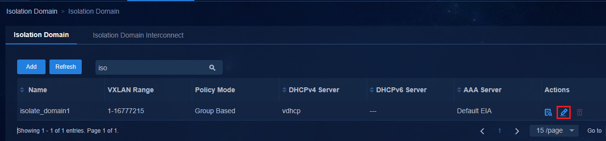
Configure a fabric
1. Navigate to the Automation > Campus Network > Fabrics page, and click Add to open the fabric configuration page.
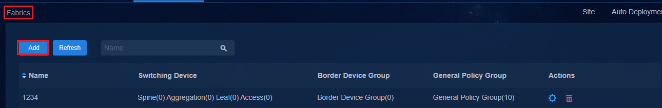
2. Configure a fabric on the fabric configuration page as follows:
¡ Name: Enter the name with no limitation.
¡ AS Number: The value is an integer in the range of 1 to 4294967295. When a device is manually deployed and managed, make sure the AS number set in the fabric is the same as the BGP AS number manually configured on the device.
¡ Isolation Domain: Select the isolation domain that the fabric belongs to.
¡ Multicast Network: It is Off by default. You can select On if necessary.
¡ QoS policy: It is Off by default. You can select On if necessary.
¡ Lock Underlay: It is Off by default and cannot be edited when you add a fabric. Disable it during automated device deployment, and enable it as required after automated device deployment is completed.
¡ Delayed Access Interface PVID Assignment: It is Off by default and the controller will automatically assign PVID when the device is activated. If you select On, the controller will not assign PVID when the device is activated, and you can manually configure the PVID after the device is activated.
¡ Virtual Auto Online And Business Follow: The default setting is On. It is used to control the authorization of the VXLAN networking and the authorization of access policies between security groups. Read the prompt information of the configuration before operating.
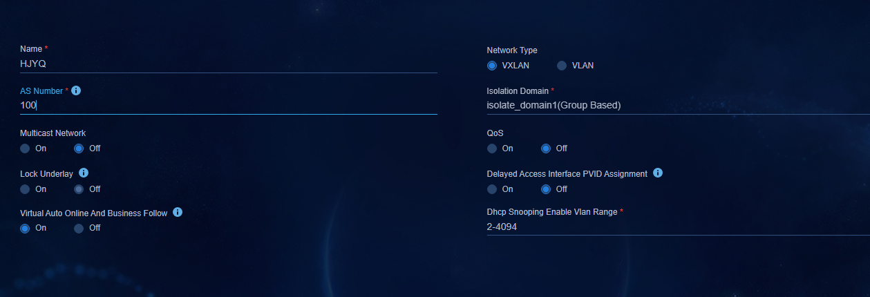
3. Click OK to complete the fabric creation. The added fabric is displayed on the Fabrics page. The system creates 11 general device groups for each fabric by default.
Incorporating a device
You can manually incorporate devices or enable automatic incorporation of devices.
Manual incorporation
To configuring spine and leaf devices, navigate to the Guide > Add Device page and configure the following parameters:.
· Host Fabric: The fabric must use the group-based policy mode.
· Device Role: Options include Spine, Leaf, Access, and Aggregation. Make sure the selected role is consistent with the actual role configured on the device.
· Management IP: Enter the IP address of VXLAN-interface 4094/VLAN-interface 4094.
· Underlay IP: Enter the IP address of the loopback interface of the device.
· Device Series: Select the added device type.
· Device Control Protocol Template: Configure a template or select the default protocol template.

Click Edit Control Protocol Template to edit the template.
· On the Control Protocol tab:
¡ Read and Write Community: Configure the SNMP read and write community name based on the SNMP parameters configured in underlay settings.
¡ Read-Only Community: Configure the SNMP read-only community name based on the SNMP parameters configured in the underlay settings.
¡ Username: Specify the local username configured in underlay settings as the NETCONF username.
¡ Password: Enter the password for the NETCONF user. The password must be a string of 10 to 63 characters, containing at least two types of the following characters: Digits, uppercase letters, lowercase letters, and special characters. The password cannot contain Chinese characters, question marks (?), spaces, username, or username in reverse order.
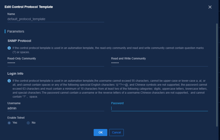
After the device is added, the initial state is Inactive. After data synchronization is completed, click Refresh. The device state will change to Active, indicating that the device is connected.
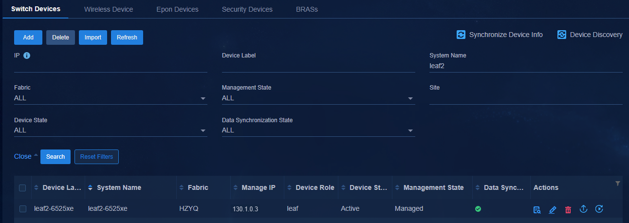
After a spine or leaf device is incorporated, you can execute the dis openflow instance 1 controller command to view detailed information about the device connected to the SeerEngine-Campus controller.
#
[SpineA]dis openflow instance 1 controller
Instance 1 controller information:
Reconnect interval: 60 (s)
Echo interval : 5 (s)
Controller ID : 1
Controller IP address : 110.1.0.103
Controller port : 6633
Local IP address : 130.1.0.101
Controller role : Slave
Connect type : TCP
Connect state : Established
Packets sent : 76
Packets received : 182
SSL policy : --
Control SSL policy : --
VRF name : vpn-default
Controller ID : 2
Controller IP address : 110.1.0.104
Controller port : 6633
Local IP address : 130.1.0.101
Controller role : Master
Connect type : TCP
Connect state : Established
Packets sent : 18
Packets received : 115
SSL policy : --
Control SSL policy : --
VRF name : vpn-default
[SpineA]
#
Incorporating access device:
When incorporating the access device, Third-party Device is set to No by default. Select Yes for third-party devices or the devices with a role that H3C does not support.
For device models that support the access role in the AD-Campus solution, see "Hardware ."
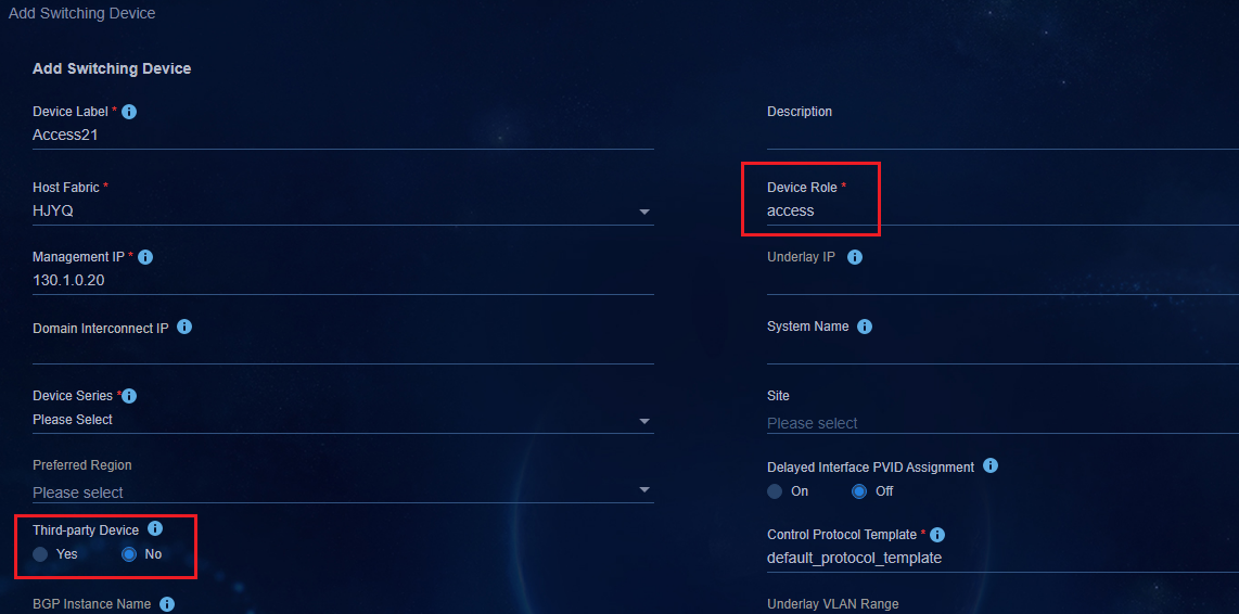
|
|
IMPORTANT: Access devices are not incorporated through OpenFlow. You cannot view OpenFlow connection information on the access devices. |
Incorporating aggregation device:
Between spine and leaf devices, aggregation device needs basic configuration for the controller incorporation before device incorporation. For the basic configuration of aggregation devices, see "Configure aggregation devices."
Leaf devices connecting aggregation devices have the same basic configuration as the standard networking of the AD-Campus solution. For the configuration, see "Configure leaf devices."
Configure the device settings as follows:
· Device Role: Select aggregation. The controller does not check the actual device role when manually incorporating the aggregation device.
· Management IP: Enter the IP address of VLAN-interface 1.
· Underlay IP: Enter the IP address of the loopback interface of the device.
· Device Series: Select the added device type.
· Control Protocol Template: Configure a template or select the default protocol template.
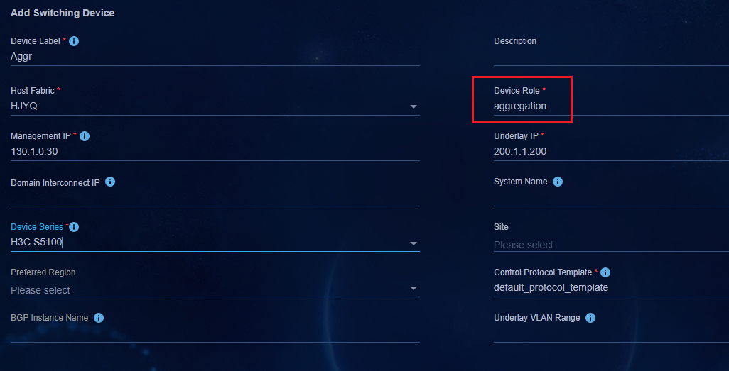
After the aggregation device is manually incorporated, the device state is Active and the device role is aggregation.
Navigate to the Monitor > Topology View > Network Topology page to view the aggregation topology view.
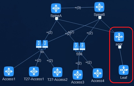
Auto discovery of APs
Navigate to the Wizard > Device Discovery page.
Configure the IP address range and SNMP parameters, and then click Create Device Discovery Task to scan devices that are not incorporated. The unincorporated devices that are discovered in the device list are as follows:
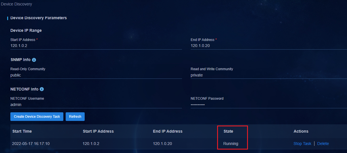
If you configure both SNMP and NETCONF
parameters, the system discovers devices through NETCONF first. To incorporate
a device, click ![]() in the Actions column for the
device. For parameter descriptions, see "Manual incorporation."
in the Actions column for the
device. For parameter descriptions, see "Manual incorporation."
Configure a policy template
You can configure a policy template in the following ways. This document describes the Campus wizard as an example.
· Campus wizard mode. Navigate to the Wizard > Campus Wizard > Device Onboarding Planning. Configure Policy Template in step 5.
· Non-Campus wizard mode. Navigate to Automation > Campus Network > Device Groups > General Policy Group, and click Policy Template at the upper right corner of the page to open the policy template page.
1. Click Policy Template at the upper right corner of the page to open the policy template configuration page as follows.
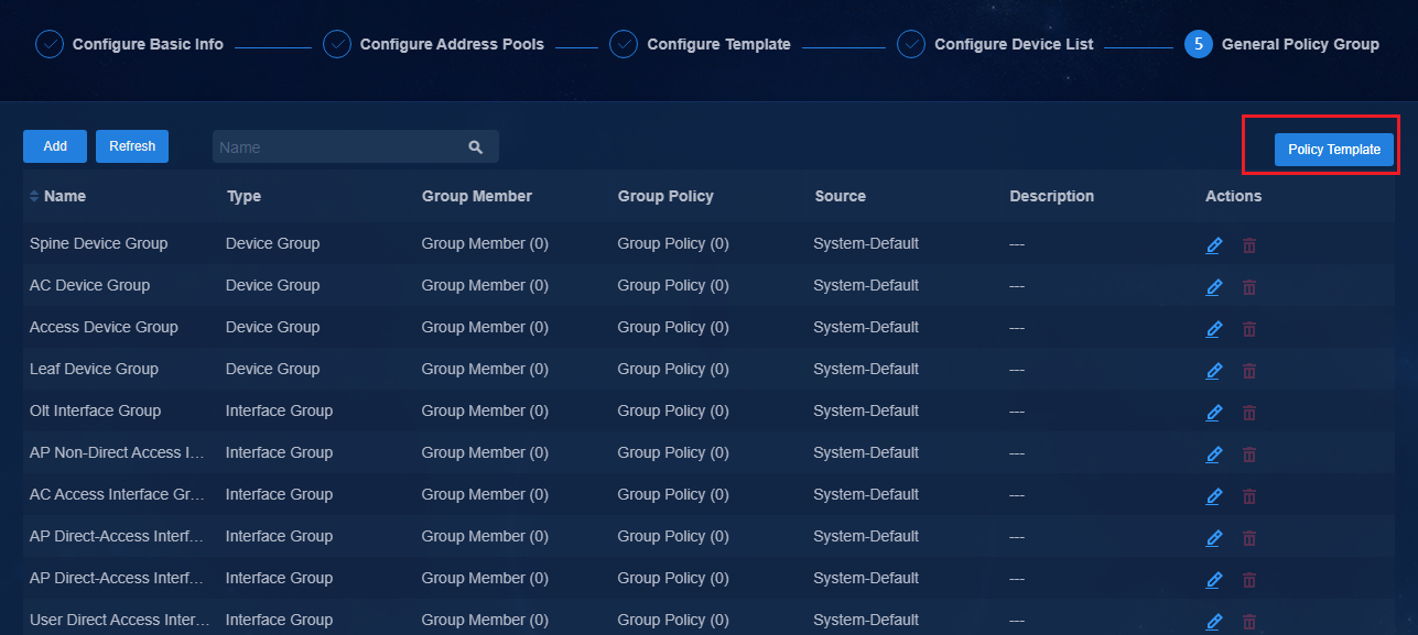
2. The system has defined the following default policies:
¡ interface_ipv4_binding: The configuration is applied to the leaf interface group for port security. The ip verify source ip-address mac-address command is issued after the policy is configured. As a best practice, do not use the current configuration.
¡ mac_migrating_enable: The configuration is applied to leaf device groups for MAC migration. The user is migrated between the same downlink port of the same leaf device or between different downlink ports. That is, you need to configure this setting when an endpoint migrates between different ports (different VLANs) on the same access device or between different access devices. The port-security mac-move permit command is issued after the policy is configured. The current solution needs the configuration.
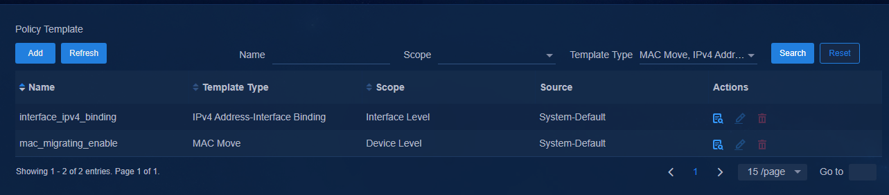
3. Click Add, and select Device Policy Template or Interface Policy Template from the drop-down list.
¡ Device Policy Template: A device policy template can be applied to a leaf device group for AAA authentication, 802.1X authentication, MAC authentication, and MAC migration configuration.
¡ Interface Policy Template: An interface policy template can be applied to a leaf interface group (mainly the leaf downlink interface groups) for 802.1X authentication and MAC authentication configuration.
|
|
IMPORTANT: The user authentication supports the 802.1X authentication mode and the MAC/MAC portal authentication mode. You need to configure only one authentication mode in actual networking. You can select an authentication mode as needed. As a best practice, do not configure both authentication modes. |
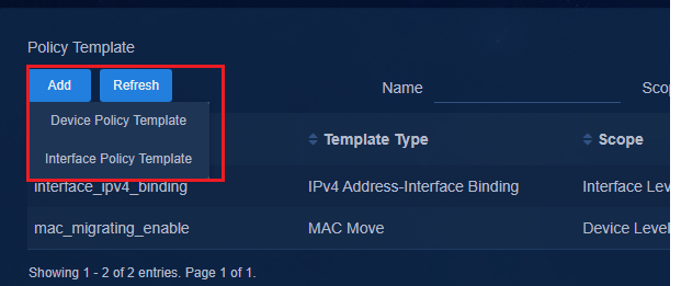
Configure, customize, and view device policy templates and interface policy templates as follows:
Device policy template-AAA
1. Configure the template name, template type, and authentication server key settings as follows:
¡ Template Name: Specify a unique template name.
¡ Template Type: Select AAA.
¡ Auth Server Shared Key: Configure the key as required. The key information will be deployed to the device and synchronized to EIA. EIA does not require this configuration. A key supports up to 64 characters and is case sensitive. Chinese characters, spaces, and special characters <>&? are not supported.
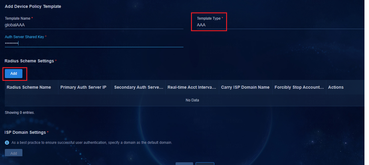
2. Radius scheme settings:
Click Add in the Radius Scheme Settings area to open the page for adding the RADIUS scheme settings. Configure the parameters as follows:
¡ Primary Auth Server IP: Specify the IP address of EIA V9 or EIA V7 used for the EIA server to perform user authentication.
¡ Real-time Acct Interval (Minute): The default setting is 15 minutes.
¡ Carry ISP Domain Name: The default setting is No.
- If Carry ISP Domain Name is set to No, the username used in the RADIUS authentication packets does not carry the domain name. By default, the EIA does not carry the domain name suffix.
- If Carry ISP Domain Name is set to Yes, the username in the RADIUS authentication packets carries the domain name, and the username must be followed by @domain name when the user comes online.
¡ Forcibly Stop Accounting When Clients Go Offline: If you select Yes, the accounting stops immediately after the client goes offline. If you select No, the accounting does not stop immediately after the client goes offline.
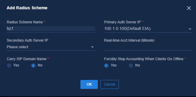
3. ISP domain settings:
Click Add in the ISP Domain Settings area to open the Add ISP Domain page. The parameters are described as follows:
¡ ISP Domain: After you specify the Radius Scheme setting, the RADIUS domain name is displayed here.
¡ Is A Default Domain: Select Yes.
¡ Is ONU Authentication: Select No.
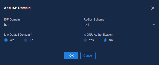
|
|
WARNING! Multiple ISP domain names can be added, but only one default domain name is allowed. Generally, you can add one RADIUS domain name and one ISP domain name. |
After the AAA template is configured, it is displayed as follows:
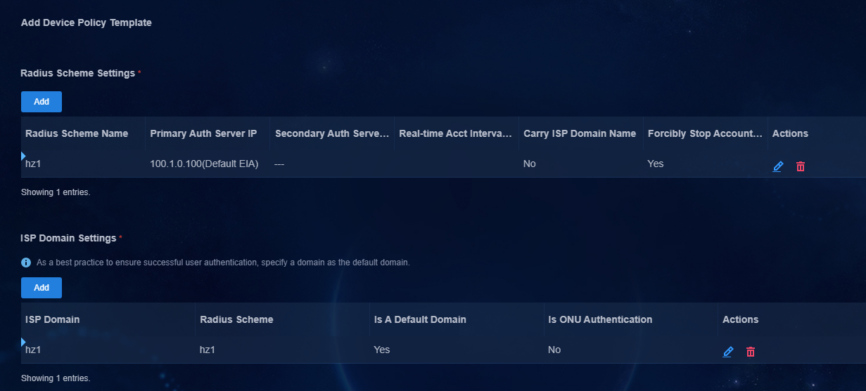
Device policy template - 802.1X authentication
· Template Type: 802.1X authentication.
· Authentication Method: Options include EAP, CHAP, and PAP. As a best practice, select CHAP for wired authentication, and select EAP for wireless authentication.
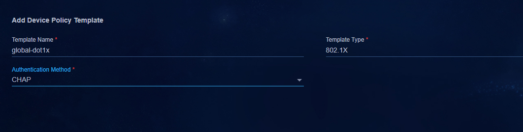
Device policy template - MAC/MAC Portal authentication
· Template Type: MAC/MAC Portal authentication.
· Portal Authentication: Select Yes.
· Authentication-Free IPs: You must specify the IP address of the EIA server as an authentication-free IP if Portal authentication is enabled. If the EIA is the active/standby environment, you need to add the addresses of the two EIA servers.
|
|
IMPORTANT: When the AAA template is configured with primary and backup authentication servers, you must configure the IP addresses of the primary and secondary authentication servers as authentication-free IPs. For the configured authentication-free IP addresses, after the policy template is deployed to the leaf device, the controller will deploy a supernet recursive route for the authentication-free IPs to the leaf device to ensure that the leaf can reach EIA. |
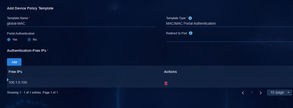
Interface policy template - 802.1X authentication
· Template Type: 802.1X authentication.
· Enable The Escape Function: The default setting is Yes. You can disable this feature as needed.
· Unicast Trigger: The default setting is Yes. Use the default setting.
· Guest Access: Select No. The 802.1X guest function, authentication failure function, and MAC Portal authentication cannot be used on the same interface. Configure this parameter as needed.
· Access on Authentication Failure: The default setting is Yes. The 802.1X guest function, authentication failure function, and MAC Portal authentication cannot be used on the same interface. Configure this parameter as needed.
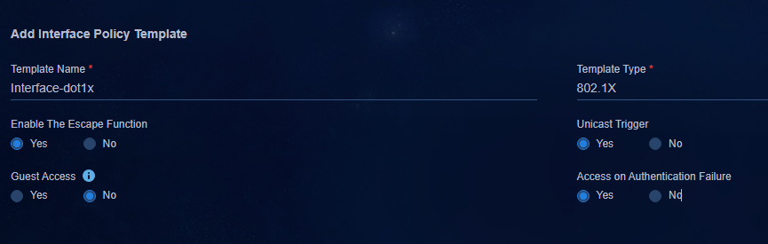
Interface policy template - MAC/MAC-Portal authentication
· Template Type: MAC/MAC Portal authentication.
· Domain Name: The domain name in the previous AAA configuration is displayed in the Domain Name drop-down box. If it is not set, the global default domain name set in AAA is used.
· Enable The Escape Function: The default setting is Yes. You can disable this feature as needed.
· Perform MAC Authentication in Parallel with 802.1X Authentication: The default setting is Yes. Use the default setting.
· Include User IP Addresses in MAC Authentication Requests: The default setting is No. If you select Yes, the mac-authentication carry user-ip command is issued to the interface for user authentication for endpoint configurations as static IP.
|
|
IMPORTANT: · Restrictions of the mac-authentication carry user-ip command: Configure this command only for By IP Range authentication and when Bind User IP Address authentication is configured in the access policy. In any other cases, do not configure this command. If the endpoint device needs to be configured with a static IP address for authentication, the controller delivers the static IP address to EIA by issuing the ARP snooping command. · For information about special restrictions to the mac-authentication carry user-ip command, see "Fast online based on IP address ranges." |
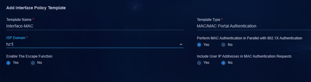
Customize a policy template
Besides the default policy templates, you can also configure device policy templates and interface policy templates. The following uses the user-defined template of interface group configuration:
· Template Type: Select User-Defined.
· Configuration Deployed When The Policy Is Added: Specify the commands to be deployed to the members in a group when the group is bound to the policy.
· Configuration Deployed When The Policy Is Removed: Specify the commands to be deployed to the members in a group when the group is unbound from the policy. This parameter must be configured. Otherwise, the policy issued cannot be removed.
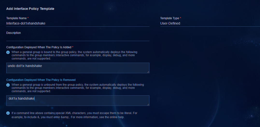
View policy template content
After the policy template is configured,
you can click ![]() in the Actions column
for the template to view its details, and click
in the Actions column
for the template to view its details, and click ![]() to
edit the template. User-defined policy templates cannot be edited.
to
edit the template. User-defined policy templates cannot be edited.
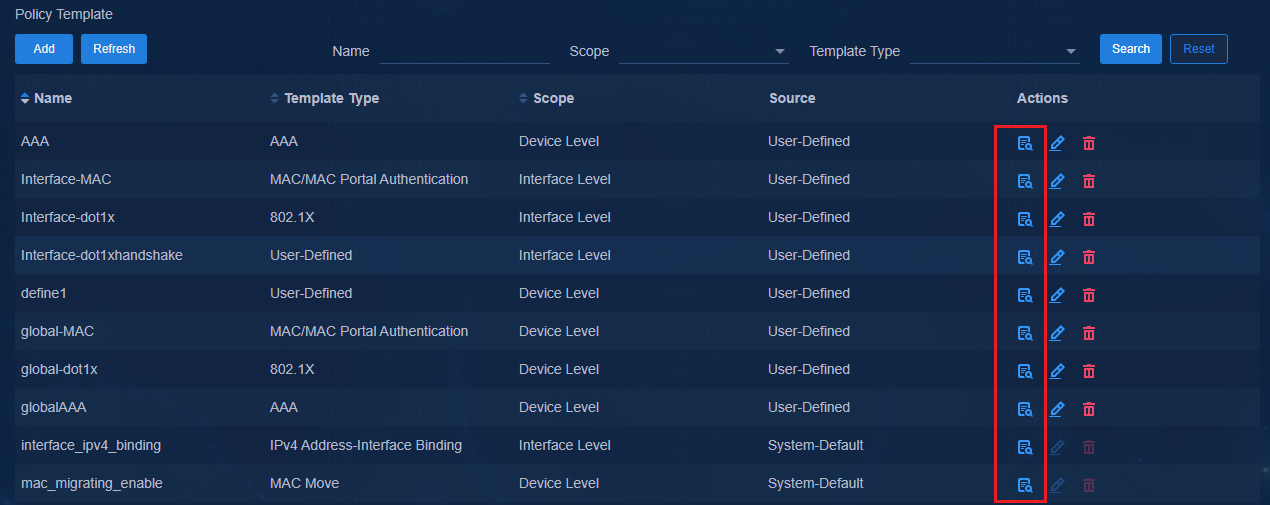
|
|
IMPORTANT: Configuring a policy template does not deploy any configuration to a device. To deploy the configuration to a device, you must apply the policy template to the device group of the device. |
Device group-group policy
1. Configure the device policy template of AAA authentication, 802.1X authentication, MAC authentication and mac_migrating_enable MAC migration. You can also configure the user-defined policy template.
Click ![]() in the Actions
column corresponding to Leaf Device Group in the list. Click the Policy
tab, and click Add to open the page for adding a device group policy.
in the Actions
column corresponding to Leaf Device Group in the list. Click the Policy
tab, and click Add to open the page for adding a device group policy.
¡ Interface Isolation Device Group: Not selected by default.
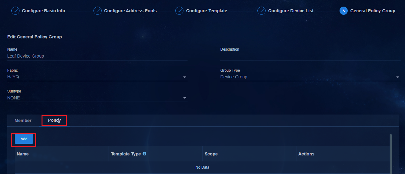
2. In the Available Policy Templates column, select a template type. After the template type is selected, the created policy template is displayed in the Available AAA Policies column on the right. Select a policy template and click Add to add the policy.
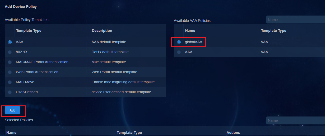
3. Add 802.1X authentication, MAC/MAC-Portal authentication, and MAC_MOVE in the same way. Click OK to save the configurations.
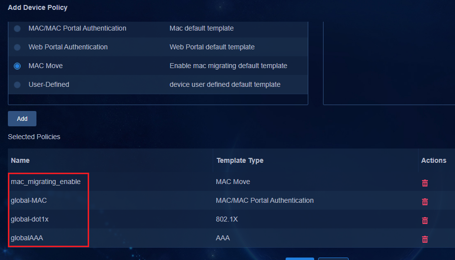
Interface group-group policy
Configure the interface group policy in Leaf Downlink Interface Group in the same way the device group policy is configured. In the Leaf Downlink Interface Group, select the previously configured user authentication and custom policy templates.
Select 802.1X or MAC authentication for the policy template as needed. This example uses MAC authentication as shown in the following figure.
|
|
IMPORTANT: · Both 802.1X authentication and MAC/MAC Portal authentication are supported. Configure one authentication method as needed. As a best practice, do not configure both authentication methods. · The group policy of the device group and the group policy of the interface group must use the same authentication method. |
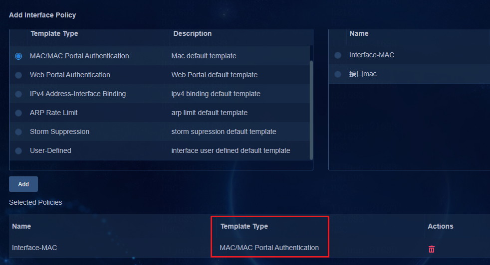
Configure access network settings
This document uses the Campus wizard to configure the access network. Select Wizard > Campus Wizard > Access Network Planning. Access network settings include the configuration of isolation domains, private networks, Layer 2 network domains, and security groups.
Configure isolation domains
Isolation domains are used to isolate user networks. The IP address ranges in an isolated domain are the same, and the IP address segments in different isolated domains are different. Each isolation domain has its DHCP system, authentication system, and wireless AC. Isolation domains are generally divided based on physical locations, such as a campus in a company, a hospital ward, or a school campus.
An isolation domain can contain multiple fabrics, but a fabric can belong to only one isolation domain.
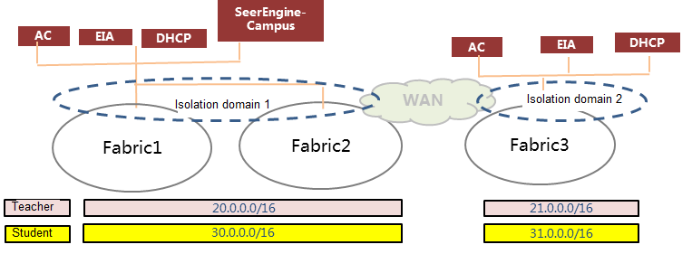
There are two ways to configure an isolation domain. This document uses the Campus Wizard as an example.
· Campus wizard mode. Navigate to the Wizard > Campus Wizard > Access Network Planning page, and click the Isolation Domain tab in the first step Isolation Domain.
· Non-Campus wizard mode. Navigate to the Automation > Campus Network > Isolation Domain > Isolation Domain page.
1. The system has defined a default isolation
domain named isolate_domain1. The default policy mode for an isolation
domain is IP Based. You can click ![]() for the isolation
domain to open the page for editing the isolation domain. In microsegmentation
networking, set it to Group Based.
for the isolation
domain to open the page for editing the isolation domain. In microsegmentation
networking, set it to Group Based.
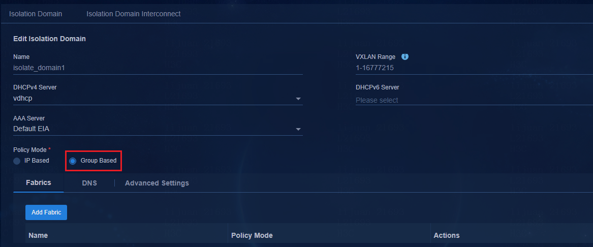
2. Configure the isolation domain, including specifying the DHCP server and setting policy mode and binding Fabric.
¡ DHCP Server: Specify the DHCP server used by the isolated domain. The DHCP server includes DHCPv4 Server and DHCPv6 Server. Select the server according to the actual networking.
- DHCPv4 servers support both tight coupling and loose coupling. In tight coupling, the security group address pool will be automatically deployed to the DHCP server. In loose coupling, the security group address pool will not be automatically deployed to the DHCP server. You need to create the address pool manually on the DHCP server.
- DHCPv6 servers support only loose coupling. You need to create manually the address pool on the DHCP server.
¡ Policy Mode: The default setting is IP Based. In microsegmentation networking, set it to Group Based.
¡ Add Fabric: Select fabrics for the isolation domain. The policy mode for the isolation domain needs to be the same as the fabric policy mode. Only fabrics that use the same policy mode as the isolation domain can be selected.
¡ Add Fabric Connection: It is applicable to multi-fabric networking. Different fabrics establish EBGP connections with each other. The parameter is not required in a single-fabric network.
¡ DNS: IP address on the DNS server that the specified isolation domain uses.
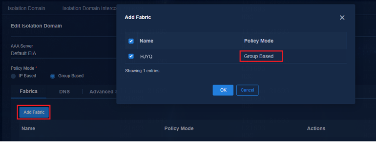
Configure private networks
Create a private network
There are two private network configuration methods. This document uses the Campus wizard to describe the configuration.
· Campus wizard mode. Navigate to the Wizard > Campus Wizard > Access Network Planning page, and click the Private Network tab in the second step Private Network.
· Non-Campus Wizard mode. Navigate to the Automation > Campus Network > Private Network > Private Network page.
1. After completing the configuration, click Next to open the page for private network configuration. Click Add to open the page for adding the private network.
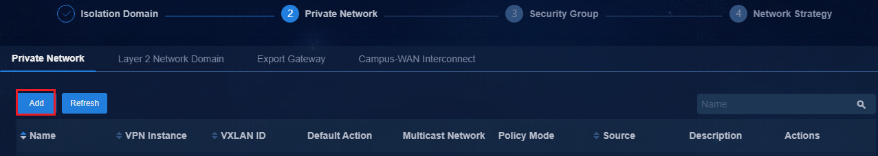
2. Enter the configuration parameters in the input box on the Add Private Network page, and click OK to save the configuration.
¡ Share VRF: It is set to No by default. Use the default value. Shared VRFs are used for shared egress gateways and can only be used when creating shared egress gateways and creating IT resource groups that shared gateways access.
¡ XVLAN ID: Specify the L3 VNI for the private network. The default value is Auto.
¡ Default Action:
- Permit: All users in the private network can access each other by default.
- Deny: All users in the private network cannot access each other. In the micro-segmentation scheme, when setting the Default Action to Deny, not only users between security groups cannot access each other, but also users within security groups cannot access each other.
¡ Multicast Network: Configure this parameter as required.
¡ Policy Mode: For microsegmentation networking, select Group Based.
¡ Policy Applied to: When you configure an inter-group policy, the IPv4 policy is deployed. To deploy an IPv6 inter-group policy, select the IPv6 Users option. If IPv6 is selected, service chain policy templates cannot be applied to this private network.
¡ Communicate with vpn-default by: Options include RT Import and Static Route. RT import is the default setting. The user's private network and vpn-default are interconnected through RT import. The static route is a new communication way. The user's private network imports the RT of vpn-default, and vpn-default uses a static route to the user's private network for communication.
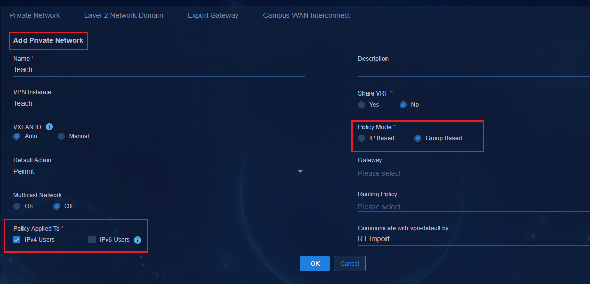
|
|
IMPORTANT: A private network and an isolation domain are bound to each other through a Layer 2 network domain. If a private network is not bound to an isolation domain, the configuration of the private network will not be deployed to devices in the isolation domain. |
Create a Layer 2 network domain
There are two modes for configuring a Layer 2 network domain. This document uses the Campus wizard to describe the configuration.
· Campus wizard mode. Navigate to the Wizard > Campus Wizard > Access Network Planning page and click the Layer 2 Network Domain tab to configure in the second step Private Network.
· Non-Campus wizard mode. Navigate to the Automation > Campus Network > Private Network > Layer 2 Network Domain page.
1. After creating the private network, click Layer 2 Network Domain to open the Layer 2 network domain configuration page.
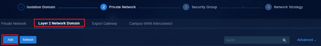
2. Click Add to open the Add Layer 2 Network Domain page. You need to create a Layer 2 network domain for BYOD and a Layer 2 network domain for private network users.
¡ BYOD Layer 2 network domain: The BYOD Layer 2 network domain is used for MAC Portal authentication.
- Private Network: Select vpn-default.
- Type: Select BYOD.
- DHCPv4 Server: For the BYOD security group, select vDHCP.
- IP Address Lease Duration: The default lease of the BYOD address pool is 60 seconds. The value can be modified as required. As a best practice, set a value longer than 30 seconds.
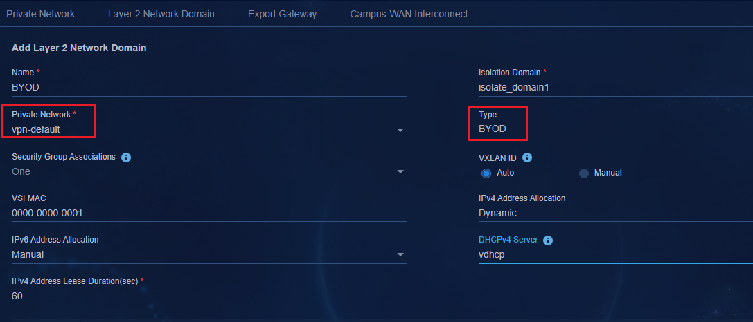
¡ User service L2 network domain:
- Private Network: Select the private network created by the user. After the Layer 2 network domain is created, the configuration of the private network will be deployed to the devices in the specified isolation domain.
- Type: Select Normal for user services. Layer 2 Domain Support Types: Normal, Escape, Guest, Authentication Failed, Escape & Authentication Failed.
- Usage: There are three options Exclusive, Shared, and Static access.
Exclusive: A Layer 2 network domain can be assigned to only one security group.
Shared: A Layer 2 network domain can be assigned to multiple security groups, and all security groups bound to the same Layer 2 network domain share the same IP address segment. It applies when the IP address segments are the same but the service access requirements are different.
Static access: Applies to services with static AC authentication in microsegmentation scenarios.
- IPv4 Address Allocation: Dynamic means that users obtain IP addresses from the DHCP server. Manual means that no DHCP address pool is configured and you need to configure IP addresses manually. When you select Dynamic, you can set the address lease. The default value is 1 day.
|
|
IMPORTANT: When obtaining IPv4 addresses dynamically, if some of the user endpoints onboard by configuring a static IP address, you need to manually add the static IP address configured on the Network Parameters > DHCP Server > IP Prohibits Assigning Addresses page. |
- IPv6 Address Allocation: Options include Manual, SLACC, Stateful DHCPv6, and Stateless DHCPv6. For detailed IPv6 configuration, see AD-Campus 6.2 IPv6 Service Configuration Guide.
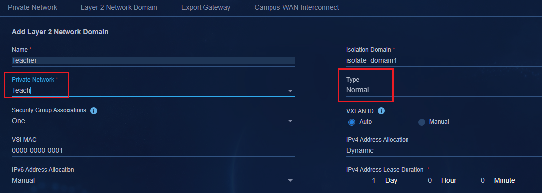
3. On the Subnets tab, click Add to open the Add Subnet page. Configure the subnet parameters, and then click OK. Select On or Off for Secondary in the Add Subnet page.
¡ If you select No, the subnet will be used as a primary network. If the IPv4 address allocation mode is dynamic, the system will create an address pool on the DHCP server based on the subnet address.
¡ If you select Yes, the subnet will be used as a secondary network. The system will not create an address pool on the DHCP server based on the subnet address. It is applicable when endpoints use static IP addresses. Before creating a secondary network, make sure a primary network has been created. In addition, the Bind User IP Address function cannot be used in the access policy when a secondary network is used.
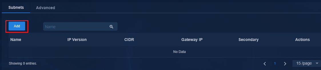
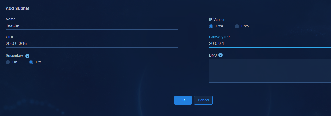
|
|
IMPORTANT: · A layer 2 network domain can have only one primary network segment and multiple secondary network segments. Plan the IP addresses based on the actual network conditions. Different security groups require different IP address ranges. · Before creating a secondary network, make sure a primary network has been created. · In addition, the Bind User IP Address function cannot be used in the access policy when a secondary network is used. · A secondary network cannot overlap with the primary network. This feature is mainly used to keep the addresses of the endpoints (printers) unchanged in the network transformation scenario, to assign the segments of multiple terminals into one security group, and to save ACL resources. · DNS Info: Specify the DNS server IP address for the Layer 2 network domain. |
4. After configuring the subnet, click OK to return to the page for adding Layer 2 network domain. Click the Advanced tab to configure the parameters as needed. In this example, the default settings are used.
¡ ARP Proxy: The default setting is On.
¡ ARP Packet Validity Check: The default setting is Off. It is generally used on access devices to prevent attacks by detecting and discarding ARP packets of illegal users and gateways. When the IPv4 address obtain method is Manual, this function cannot be enabled.
¡ ARP Snooping: Select whether to enable ARP snooping to provide fast ARP responses. Select On when Broadband IoT terminals are not offline.
¡ Allow Layer 2 Application: The default setting is Off. If On is selected, it indicates that the created security group Supports Layer 2 Application supports layer 2 interworking within the security group.
¡ ARP Scan and Probe: The default setting is Off. If On is selected, ARP broadcast will not flood the whole network. ARP learning depends on local scanning of Leaf devices. Table entries are synchronized through EVPN. The switch will not forward ARP messages.
¡ IPv6 ND Detection: This feature is used to verify the legitimacy of users.
¡ IPv6 ND Snooping: The device creates ND snooping entries by listening to ND or data packets. Do not enable IPv6 ND Snooping when no IPv6 services are available.
¡ ND Scan and Probe: The default setting is Off. If On is selected, ND broadcast will not flood the whole network. ND learning depends on local scanning of Leaf devices. Table entries are synchronized through EVPN. The switch will not forward ND messages.
¡ DHCPv6 Snooping: The default setting is No. DHCPv6 snooping ensures that the client obtains IPv6 addresses or IPv6 prefixes from valid servers, and can record the correspondence between IPv6 addresses or IPv6 prefixes of the DHCPv6 client and MAC addresses.
¡ DHCPv6 Trunk Supports Option79: The default setting is On. It is used to ensure that the DHCPv6 server can obtain the MAC address of the client.
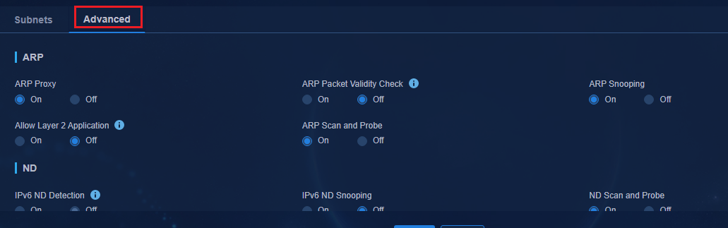
|
|
NOTE: · If you select Yes, the security group allows packets of broadcast, unknown multicast, unknown unicast to be forwarded to AC interface and flooded to the Tunnel interface and allows VXLAN MAC synchronization through EVPN. The SeerEngine-Campus controller will not deploy the flooding disable all all-direction or mac-advertising disable command to devices. · If you select Yes, you need to configure broadcast suppression for the Leaf downlink interface. The specific threshold shall be determined according to the equipment type and the number of field messages. As a best practice, consult the corresponding product R&D staff. |
If Allow Layer 2 Application are enabled, storm suppression can be delivered only from physical interfaces, not aggregation interfaces. If the Leaf downlink port is an aggregation port, perform the configuration as follows:
a. Configure user-defined policy template
Navigate to the Automation > Campus Network > Device Groups > General Device Groups page, and click Policy Template at the upper right corner of the page to open the policy template page. Click Add and select the Interface Policy Template from the drop-down list. Select the template type item as User-Defined, and add the following command to the corresponding text box as shown below.
Configuration deployed when the policy is added:
#
broadcast-suppression pps 100 // Set the threshold according to the device model and the number of messages. For more information, as a best practice, consult the corresponding product R&D staff.
multicast-suppression pps 100
unicast-suppression pps 100
#
Configuration deployed when the policy is removed:
#
undo broadcast-suppression
undo multicast-suppression
undo unicast-suppression
#
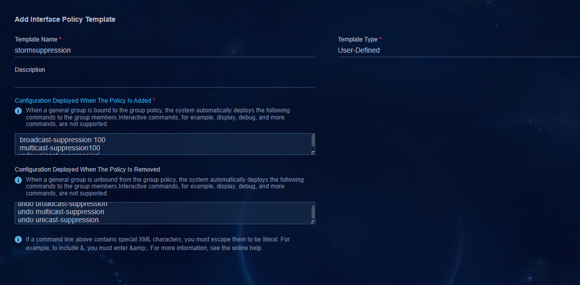
b. Configure a user-defined interface group
Navigate to the Automation > Campus Network > Device Groups > General Device Groups page, and click Add to open the page for adding the general device group. Select Interface Group for the group type and Layer 2 Physical Interface Group for the subtype.
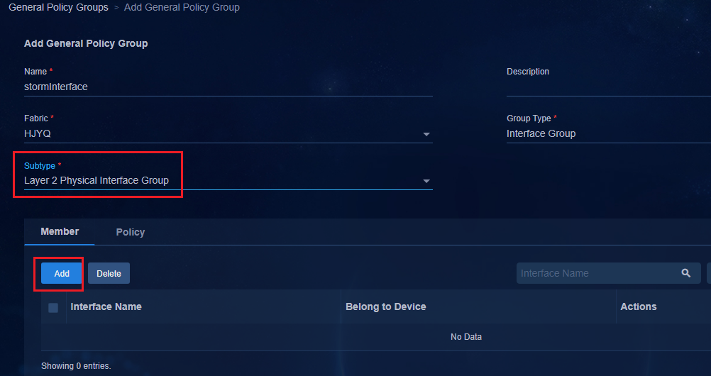
On the page, select Member and click Add to open the page for adding interfaces. Select the member interfaces included in the Leaf downlink aggregation port for which storm suppression is to be configured. Click Add to add the selected interfaces to the list.

After the member is selected, click OK to return to the Add Universal Device Group page. Click the Policy tab and click Add. On the page for adding an interface group policy, add the User-Defined storm suppression policy. After completing the configuration, click OK.
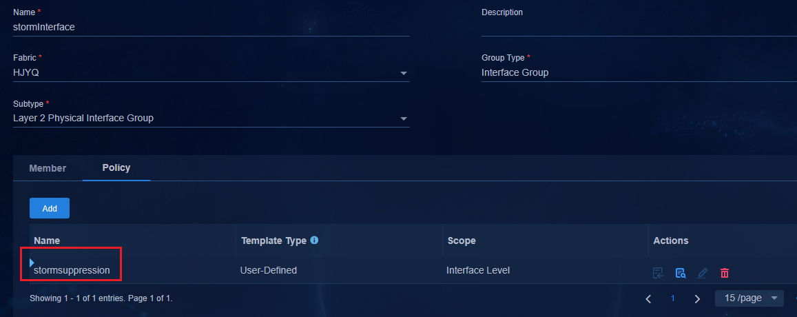
After the configuration is completed, you can view the delivered storm suppression configuration on the member interface.
#
interface Ten-GigabitEthernet0/0/8
port link-mode bridge
port link-type trunk
port trunk permit vlan 1 101 to 3000 4093 to 4094
broadcast-suppression pps 100
multicast-suppression pps 100unicast-suppression pps 100
port link-aggregation group 1024
#
|
|
IMPORTANT: ARP proxy, ARP detection, Allow Layer 2 Application, IPv6 ND detection, VSI MAC addresses and Segment ID of the Layer 2 network domain are delivered once and cannot be modified later. Therefore, confirm the functions that you want to enable before performing the configuration. |
Configure a security group
|
|
NOTE: · In the microsegmentation feature, a security group can be understood as a microsegment. When creating a security group, the controller deploys microsegmentation configuration to the device. The security group ID is the microsegment ID. · A security group can cross isolation domains. A security group can be bound to Layer 2 network domains of multiple isolation domains. You can assign the same microsegment ID to devices in multiple isolation domains. · Microsegmentation associates users with security groups (microsegments) and decouples users from IP address segments. A user can use the same account and password to come online in different isolation domains. EIA assigns the same microsegment ID to the user based on the account and password, realizing the Uniform UX and global uniform policy enforcement. |
There are two security group configuration methods. This document uses the Campus Wizard as an example.
· Campus wizard mode. Navigate to the Wizard > Campus Wizard > Access Network Planning page, and click the User Security Group tab to configure in the third step Security Group.
· Non-Campus wizard mode. Navigate to the Automation > Campus Network > Security Group > User Security Group page.
1. After Private Network is created, click Next to go to the Security Group page. Select the User Security Group tab and click Add to go to the page for adding security groups. Enter a name for the security group, select a private network, and select Normal for the Type.
Type: BYOD, Normal, Authentication Failure, and External Network.
¡ BYOD: A BYOD security group is used for MAC Portal authentication. Before MAC authentication, a user will join the BYOD security group. The system has defined a default security group named BYOD_Security Group. Only one BYOD security group is supported globally.
¡ Normal: A normal security group is used for user services. All basic services use normal security groups.
¡ Authentication Failure: A fail-permit security group is used in fail-permit scenarios. When the EIA server fails, users can still come online and access the resources in the fail-permit security group. Only one fail-permit security group can be configured in an isolation domain.
¡ External Network: An external network security group is used for south-north service chains. For more information, see AD-Campus 6.2 Service Chain Configuration Guide.
2. Click Isolation Domains and click an isolation domain from the drop-down box. An isolation domain must be selected before adding a Layer 2 network domain in the security group.

3. Click the Layer 2 Network Domain tab
and click Add to open the page for adding Layer 2 network domains.
Select a Layer 2 network domain in the Available Layer 2 Network Domain
column and click ![]() to add the selected Layer 2 network domain to the Selected Layer
2 Network Domain column. Then, click OK to return to the page for
adding a security group.
to add the selected Layer 2 network domain to the Selected Layer
2 Network Domain column. Then, click OK to return to the page for
adding a security group.
4. After you select On for the Security Subgroup, the Max Subgroups list and the Security Subgroups will be displayed as follows:
The Max Subgroups list has four options: 1, 3, 7, and 15. It limits the maximum number of security subgroups that can be created for a security group. Up to 15 can be created. After you select an option for Max Subgroups, you can create a maximum of security subgroups with the selected capacity on the Security Subgroup tab.
|
|
IMPORTANT: · Security subgroups are optional to a security group. · Microsegmentation supports sub security groups. A security group supports multiple sub security groups. A sub security group can inherit the permissions of its parent group, and you can also configure permissions for the sub group separately. A sub security group is used for the exception configuration of the inter-group policy. In a security group, you can assign roles with a specific permission to a sub security group for fine-grained permission control. |
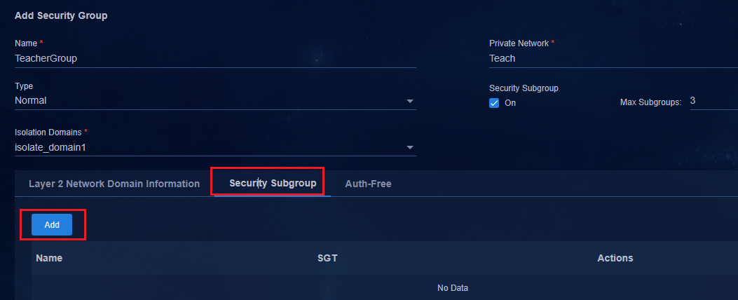
5. After a security group is created, you can view it on the User Security Group page.
Value 3504 is the security group ID, and the controller will deploy microsegment ID 3504 to the device. Value 1/3 in the sub security group column indicates that one sub security group has been created and a maximum of three sub security groups can be created for the security group.
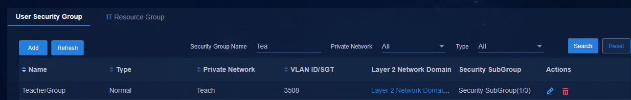
6. After you create the security group and sub security groups, the controller deploys the microsegmentation configuration to the device.
# Deploy microsegment ID 3504.
microsegment 3504 name SDN_EPG_3504
member ipv4 20.0.0.0 255.255.0.0 vpn-instance vpn1
#
# Deploy the sub security group configuration. You can execute the dis microsegment aggregation command to view the sub security groups.
# Deploy microsegment IDs of security subgroups 3505 to 3507.
[Leaf]display microsegment aggregation
Aggregation ID Range Aggregation name
3504 3504-3507 SDN_EPGAGG_3504
[Leaf]
Configure a network strategy
There are two methods for configuring network policies. This document uses the Campus wizard to describe the configuration.
· Campus wizard mode. Navigate to the Wizard > Campus Wizard > Access Network Planning page, and configure the network policy in the fourth step Network Policy.
· Non-Campus wizard mode. Navigate to the Automation > Campus Network > Network Policy page.
The network policy page allows you to configure the access relationships between user security groups and between a user security group and a resource group by dragging the group policy templates, which simplifies the configuration.
For example, to isolate the teacher security group and student security group, you can drag the TM1 policy template to the corresponding location and then click OK. Right-click TM1 to drag the TM1 policy template to the corresponding location.
Table 9 Policy between security groups
|
Group policies |
Student security group |
Teacher security group |
Public server |
|
Student security group |
N/A |
TM1 |
N/A |
|
Teacher security group |
TM1 |
N/A |
N/A |
Configure a time range (optional)
1. Click the Time Ranges tab to configure the time range. The time range is optional and can be set as required.
2. Click Add to set the time range on
the Add Time Range page. After the configuration is completed, click ![]() to save
the configuration and click OK.
to save
the configuration and click OK.
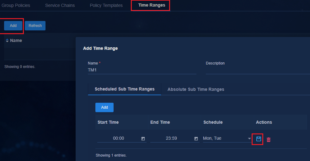
Configure a policy template
1. Click the Policy Templates tab. The system has defined two default templates Permit All and Deny All.
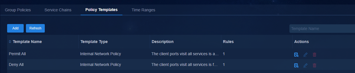
2. Click Add to open the page for adding policy templates. Enter a name for the policy template, and select Internal Network Policy for Template Type.
¡ Internal Network Policy: Select Internal Network Policy for group policies and east-west service chains.
¡ External Network Policy: Select External Network Policy for south-north service chains.
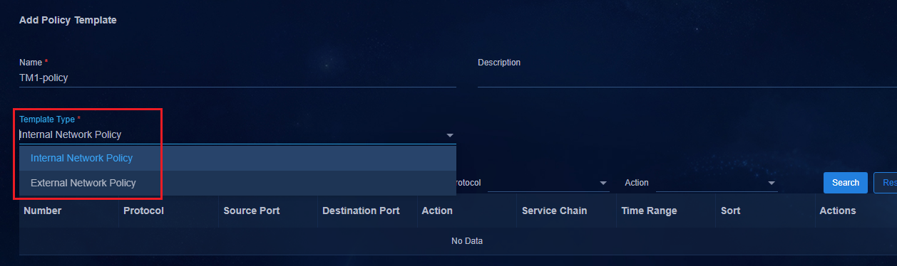
3. Click Add Rule. Set parameters and click OK to save the settings. The parameters are described as follows:
¡ Protocol Type: IP, UDP, TCP, and ICMP.
¡ Time Range: The default setting is None, indicating that all time ranges are valid. You can set it as needed.
¡ Action: Options are Permit, Deny and Redirect. Select Permit or Deny for a group policy. Redirect applies to service chains.

4. After completing the policy template addition, click OK to save the policy template.
Configure the default access policy
Click the Group Policies tab to open the group policy page. In the Default Policy column (default access policy for short) drop-down list box, you can configure access permissions for private network users. When setting a group policy, select a private network first and then set the default policy.
The default group access policy configured on the group access policy page is the same as the default group access policy configured on the private network page. You only need to configure one.
· Permit: All users in the private network can access each other.
· Deny: All users in the private network cannot access each other. In the microsegmentation solution, if you set the action to Deny, users cannot access each other regardless of whether they are in the same or different security groups. If the Default Policy is set to Deny, you need to configure a group policy for uses within the security group to communicate with each other.
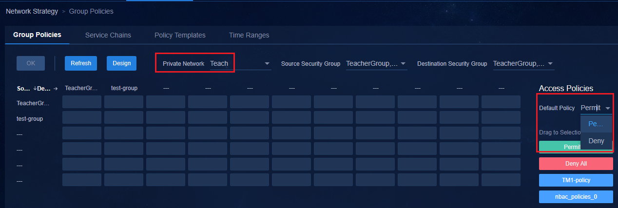
If you select Deny, the SeerEngine-Campus controller deploys the global deny PBR to the spine/leaf devices and deploys a permit IP policy to the VSI interfaces in the private network.
· Configure Permit IP for the private VSI interface of spine and leaf devices.
#
policy-based-route SDN_GLB_SC2 permit node 65535
if-match acl name SDN_ACL_SC_PERMIT_ALL
#
#
acl advanced name SDN_ACL_SC_PERMIT_ALL
description SDN_ACL_SC_PERMIT_ALL
rule 0 permit ip
#
interface Vsi-interface2
description SDN_VRF_VSI_Interface_2
ip binding vpn-instance Teach
ip policy-based-route SDN_GLB_SC2
ipv6 address auto link-local
l3-vni 2
#
· Issue deny configuration on spine and leaf devices globally.
#
policy-based-route SDN_GLOBAL_SC permit node 60000
if-match acl name SDN_ACL_GLOBAL_SC_e4a30470-a7cc-4008-8311-1e2cb1f978e5
apply output-interface NULL0
#
#
acl advanced name SDN_ACL_GLOBAL_SC_e4a30470-a7cc-4008-8311-1e2cb1f978e5
description SDN_ACL_GLOBAL_SC_e4a30470-a7cc-4008-8311-1e2cb1f978e5
rule 0 permit ip vpn-instance Teach destination microsegment 3504 mask-length 2 //Mask length of the security group. Mask length n indicates that there are a total of 2^n (4) security groups and sub security groups, and 3504 is the security group.
rule 1 permit ip vpn-instance Teach destination microsegment 3502
#
Group policies
1. Click the Group Policies tab to open the group policy page. Select Private Network and click the Private Network Tech as follows:
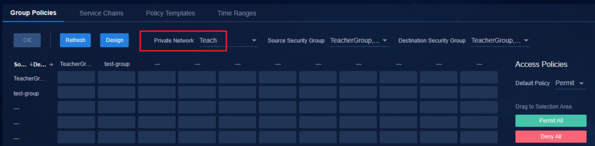
2. Select an access policy on the right and drag it to the corresponding location to open the Policy Direction dialog box. After completing the configuration, click OK to save the configuration. The Policy Direction parameter provides two options: Unidirectional and Bidirectional.
¡ Unidirectional: Source-to-destination access policy.
¡ Bidirectional: Source-to-destination and destination-to-source access policies.
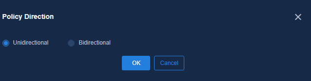
3. After completing the configuration, click OK in the upper left corner. As shown in the following figure, the Deny configuration is set for the group whose source is TeacherGroup and the destination is test-group.
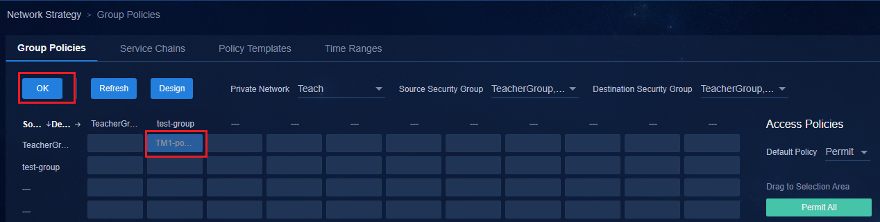
4. The controller deploys a PBR to the Spine and Leaf devices globally. The command is as follows:
#
time-range SDN_NBAC_80002p 00:00 to 23:59 off-day
#
#
policy-based-route SDN_GLOBAL_SC permit node 1
if-match acl name SDN_ACL_SC_80002q_3502_3504
apply output-interface NULL0 // Configure Deny
#
#
acl advanced name SDN_ACL_SC_80002q_3501_3504
description SDN_ACL_SC_80002q_3501_3504
rule 0 permit ip vpn-instance Teach source microsegment 3502 destination microse
gment 3504 mask-length 2 time-range SDN_NBAC_80002p
#
Exceptions
A group policy can also be configured through exceptions. Exceptions indicate special processing. You can configure exception rules to exclude specific traffic in the security group to which a group policy template has been delivered.
The exception rules in microsegmentation differ from those in IP policy as follows:
· IP address ranges are specified in the IP policy exception rules.
· Security subgroups are created in the microsegmentation exception rules.
1. Move the mouse to the middle of the security group, and a plus sign (+) will be displayed. Click + to open the Edit Group Policy page.
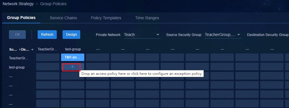
2. If a group access policy already exists,
click ![]() to open the page for editing the group access policy.
to open the page for editing the group access policy.
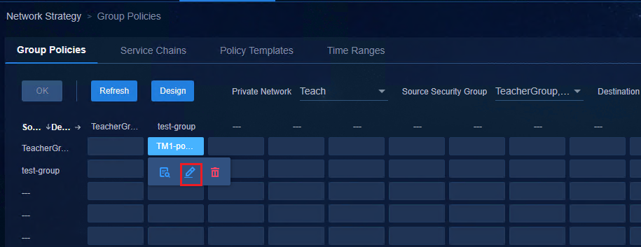
3. Click the Exception Policy tab and click the + icon to open the page for adding rules. Set rules on the page and click OK to save the configuration.
The exception policy configured in the microsegmentation is the access policy of the security subgroup. When a sub security group name is configured with an asterisk (*), the security subgroup includes the security group and all security subgroups in the security group. For example, *TeacherGroup in the figure below means security group TeacherGroup and all security subgroups in the security group.
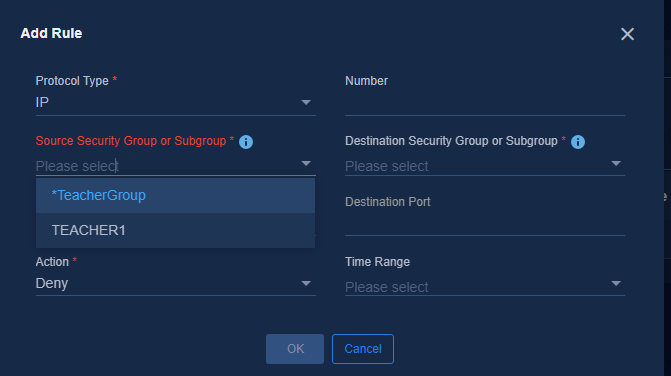
4. After the exception rules are configured, the Exceptions Policy icon will be displayed. The Campus controller will deploy the following configuration to the spine and leaf devices:
#
policy-based-route SDN_GLOBAL_SC permit node 2
if-match acl name SDN_ACL_SC_000005_3504_3504
apply output-interface NULL0
#
#
acl advanced name SDN_ACL_SC_000005_3504_3504
description SDN_ACL_SC_000005_3504_3504
rule 0 permit ip vpn-instance Teach source microsegment 3504 mask-length 2 dest
ination microsegment 3505
#
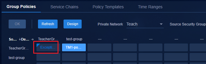
Configure user access settings
User access settings are EIA authentication server settings, including access policy configuration, access service configuration, and access user configuration. After you configure the access services, users can come online.
Configure access policies
There are two methods for configuring access policy management. This document uses the Campus wizard.
· Campus wizard mode. Navigate to the Wizard > Campus Wizard > User Onboarding Planning page, and configure in the first step Access Policy Management.
· Non-Campus wizard mode. Navigate to the Automation > User Service > Access Service page, and click the access policy link in the upper right corner to go to the access policy page.
1. Click Add to open the access policy configuration page.
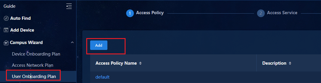
2. The access policy configuration page includes basic information, authorization information, authentication binding information, and user client configuration.
¡ Basic Information: Enter a name for the access policy and use the default service group.
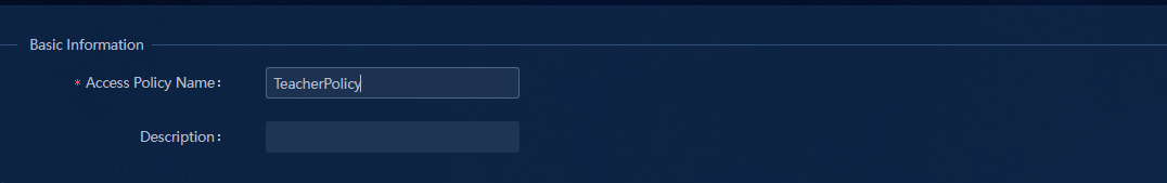
¡ Authorization information: Generally, set the default value. Configure the following parameters:
- Allocate IP: Select whether to allocate IP addresses to users. Select No for campus networks.
- Endpoint Conflict Handling:
Log Conflict and Continue Authentication: When different endpoints using the same MAC address request to come online, the system generates logs and allows the endpoints to come online after authentication.
Reject Authentication: When different endpoints using the same MAC address request to come online, the system rejects the users.
Deploy Blackhole MAC: Select this option to avoid MAC spoofing. When different endpoints using the same MAC address request to come online, the system rejects the endpoints and adds the MAC address to the silent MAC list.
- Offline Check Period (Hours): Configure this parameter to prevent the switch from logging off mute endpoints such as printers that do not send packets. The default offline detection period for MAC authentication on the switch is five minutes. The switch will log off an endpoint if it does not detect any packets from the endpoint within the offline detection period. Configure the offline check period together with ARP snooping to ensure that endpoints that pass the authentication will not be logged off. The value is an integer ranging from 0 to 596523. If this parameter is set to 0, it indicates that the system is never offline. If the parameter is none, the offline detection duration of the device is the default 5 minutes.
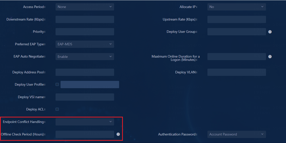
If you set the offline check period to one hour, the following configuration will be deployed to the device:
Slot ID: 1
User MAC address: 0000-0a0b-0001
Access interface: Bridge-Aggregation1023
Username: 00000a0b0001
User access state: Successful
Authentication domain: hz1
IPv4 address: 20.0.0.2
IPv4 address source: IP Source Guard
Initial VLAN: 150
Authorization untagged VLAN: N/A
Authorization tagged VLAN: N/A
Authorization VSI: vsi3
Authorization microsegment ID: 3504
Authorization ACL number/name: N/A
Authorization user profile: N/A
Authorization CAR: N/A
Authorization URL: N/A
Authorization IPv6 URL: N/A
Start accounting: Successful
Real-time accounting-update failures: 0
Termination action: Default
Session timeout period: 86400 sec
Offline detection: 3600 sec (server-assigned) // Deployed offline check period.
Online from: 12/22/2020 9:52:45 AM
Online duration: 0h 3m 2s
Port-down keep online: Disabled (offline)
¡ Pay attention to the following options in the authentication binding information:
- Bind User IP: Select this option to bind an online endpoint to its static IP address. If it is selected, the endpoint user records bound static IP addresses in the user detailed information after going online.
- Bind Dynamically Assigned IP: Select this option to bind the MAC address, DHCP-assigned IP address, and account information of an endpoint when the endpoint comes online for the first time. Then, the endpoint can obtain the same IP address every time it comes online.
|
|
IMPORTANT: Bind User IP and Bind Dynamically Assigned IP cannot be configured at the same time. |
¡ User Client Configuration: Use the default settings.
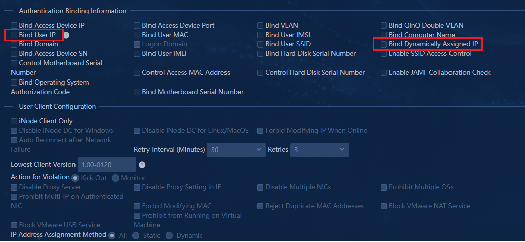
3. After setting the parameters, click OK to save the settings. The access policy will be displayed in the list.
To add more access policies, repeat the above steps.
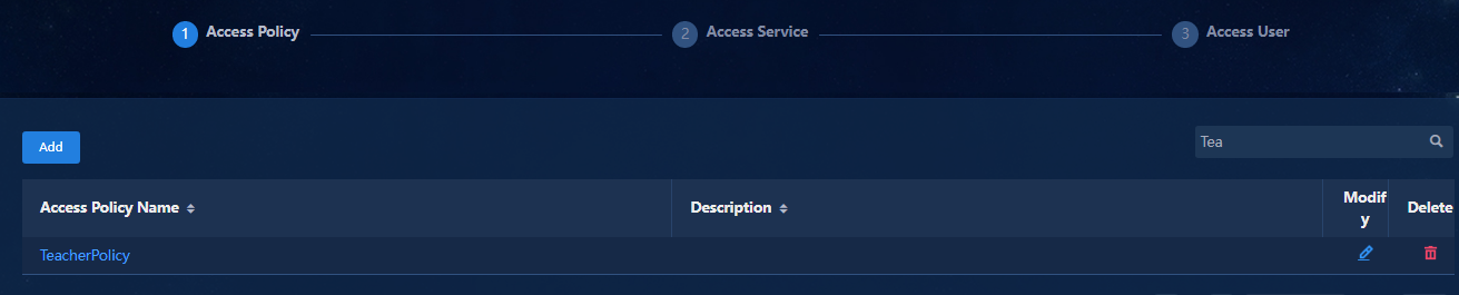
4. After configuring the access policies, click Next to configure the access services.
Configure access services
The two access service configuration methods are as follows. This document uses the Campus wizard.
· Campus Wizard mode. Navigate to the Wizard > Campus Wizard > User Onboarding Planning page, and configure in the second step Access Service Management.
· Non-Campus wizard mode. Navigate to the Automation > User Service > Access Service page.
1. Click Add to open the access service configuration page.
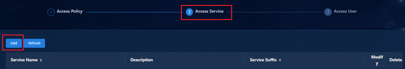
2. Configure the following parameters:
Basic Information: Enter a name for the service, select a default access policy and security group, and use default settings for other parameters.
¡ Basic information area
Descriptions for parameters in the Basic Information area:
- Service Group: It is set Ungrouped by default. Use the default setting.
- Default Access Policy: The default setting is Access Forbidden, which indicates that all users cannot come online. To allow users to come online, you must configure a default access policy. You can click Add to add new default access policies.
- Security Group: This parameter must be configured. When a user goes online, select the corresponding security group. Security groups and security subgroups created in "Configure access network settings" will be displayed in the drop-down list.
- Sub Security Group: Optional. If you select a sub security group, the access service applies to the sub security group. If you do not select a sub security group, the access service applies to the security group.
- MAC Portal Authentication/Transparent Authentication: By default, the two options are selected. To allow users that use MAC Portal authentication to come online, you must select the MAC Portal Authentication option. The Transparent Authentication is optional. (To open the redirection page for a user only when the user comes online for the first time, select the Transparent Authentication option. To open the redirection page for a user every time it comes online, do not select the Transparent Authentication option.)
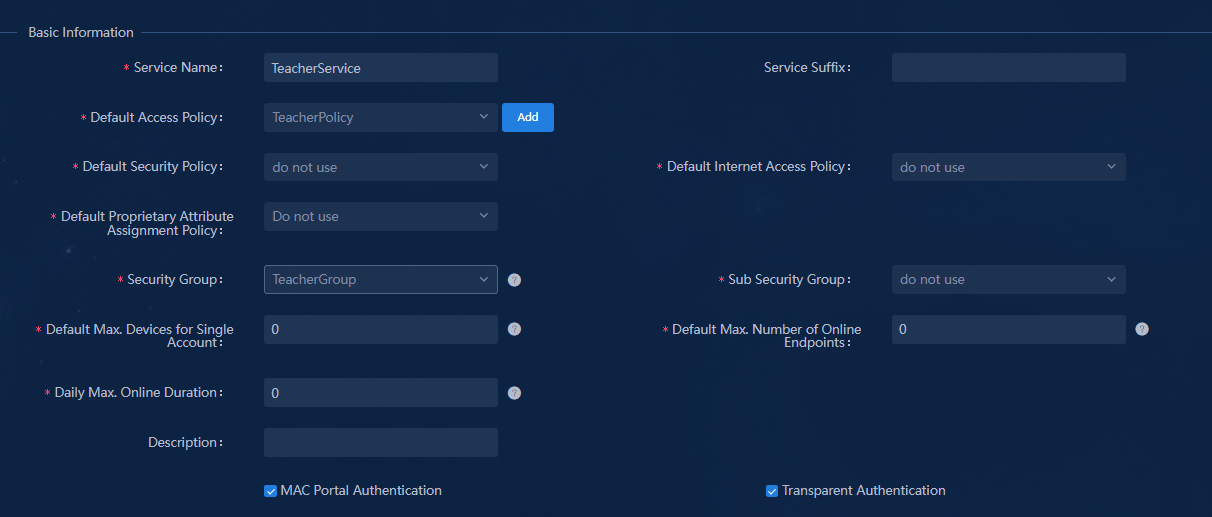
¡ Access Scenario List: Optional.
An access service can be configured with multiple access scenarios, and each access scenario is set with a security group.
When a user comes online, the system matches the user with the configured access scenarios and assigns the user to the security group specified in the matched scenario. If no match is found for the user, the system assigns the user to the security group specified in the default access policy.

|
|
IMPORTANT: As a best practice, do not configure access scenarios in the configuration wizard because the devices have not been deployed automatically. You can configure access scenarios as needed after the devices are deployed automatically. For more information, see 0"Manage access scenarios (optional)." |
3. After the access service is configured, the added access services can be viewed. To add more access services, repeat the above steps.
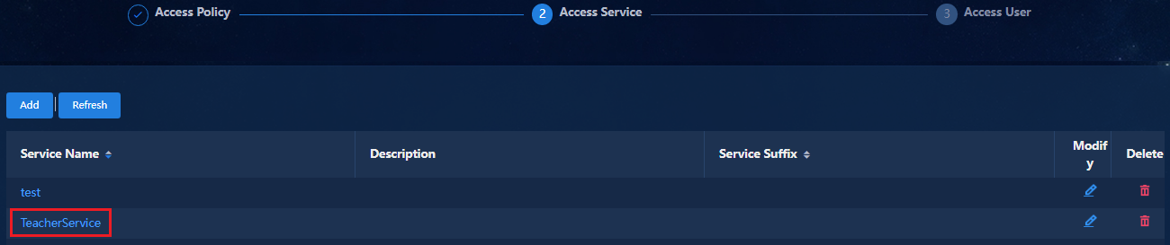
4. After configuring the access services, click Next to configure access users.
Manage access users
There are two ways to configure access user management. This document uses the Campus wizard to describe the configuration.
· Campus wizard mode. Navigate to the Wizard > Campus Wizard > Device Onboarding Planning page, and configure in the third step Access User Management.
· Non-Campus wizard mode. Navigate to the Automation > User Service > Access User page.
The access user management page supports two configuration modes: manually add and batch import. After access users are configured, all settings required on the authentication server are completed. You can perform user authentication after automatic device onboarding.
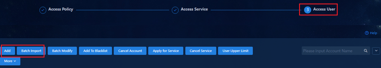
Add users manually
1. Click Add. The Add Access User page includes basic information, access information, access service, access device binding information and endpoint binding information.
¡ Basic Information: Enter the User Name and Identity Number. For other parameters, you can use the default values.
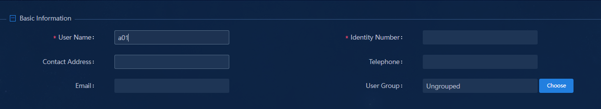
¡ Access Information: Enter the Account Name and Password. For other parameters, you can use the default values.
- Max. Idle Time: If you leave this field empty, the session never times out.
- Max. Concurrent Logins: The default value is 1. The maximum value is 255. Max. Concurrent Logins specifies the number of endpoints that use the same account for login. For detailed parameters, see "Set the maximum number of online endpoints supported by an account."
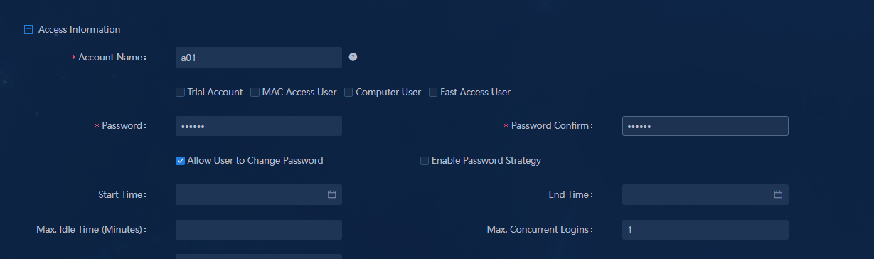
For higher security of user passwords, select Allow User to Change Password, Enable Password Strategy and Modify Password at Next Login. After you select these options, the user must change the password every time the user logs in.
|
|
IMPORTANT: The Modify Password at Next Login is a one-off option. If a user changes the password and logs in to the system successfully, this option is cleared automatically. If a user uses it again, manually select it from an access user. |
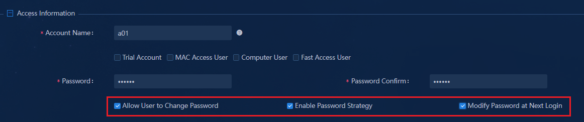
If you select Modify Password at Next Login, you will enter the page for editing the password. After the password is edited successfully, you must use the new password to log in to the system.
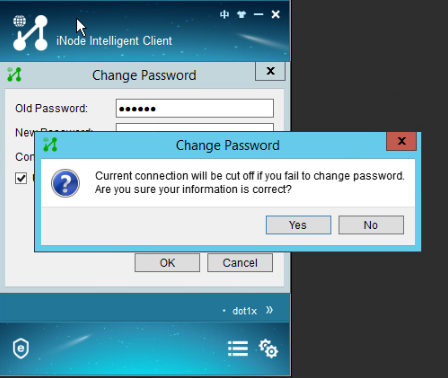
¡ Access Service: Each access user must be bound to an access service. After passing authentication, a user can access the network resources in the security group in the access service.
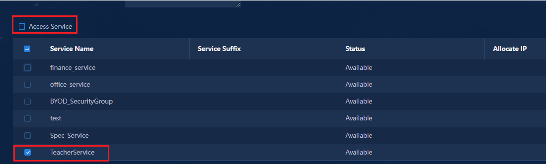
¡ Binding Information: By default, all fields are empty. You can use the default setting.
You can manually enter binding information. If you enter multiple values in a field, use carriage returns to separate the values.
The system can also specify binding information automatically based on the access service and access policy configuration.
|
|
IMPORTANT: The IP address specified in the user binding information must match the IP address of Bind User IP Address in "Configure access policies." If you do not select Bind User IP Address in access policies, the IP address specified in the binding information column will not take effect. |
2. Click OK. On the Access User page, you can view the successfully created users.
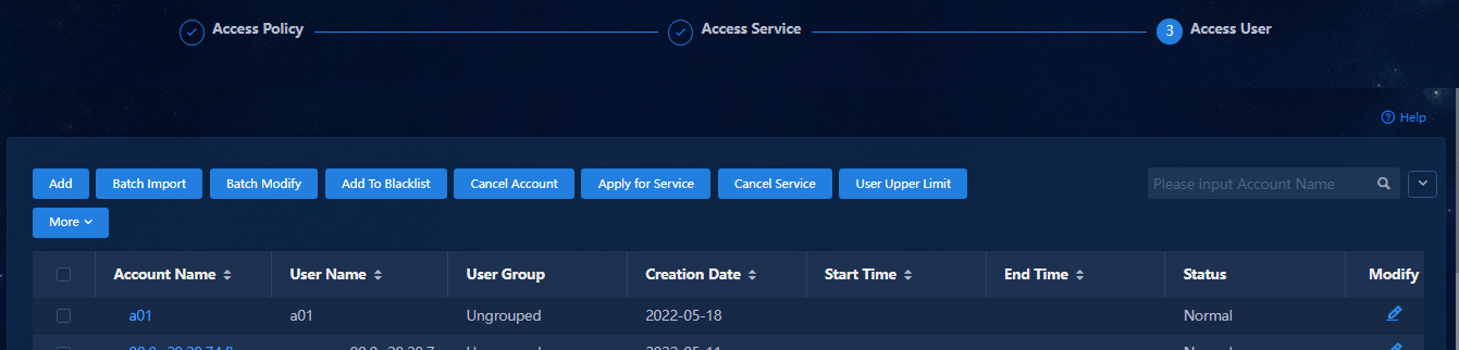
Batch import users
1. Click the Batch Import button to open the batch import page. Click Account Import File Template to download a template. You can use the TAB key or other separators such as commas (,) to separate columns.
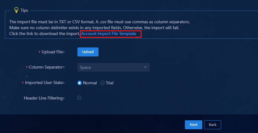
In this example, the file format of bulk importing is EXCEL, as shown in the figure below:
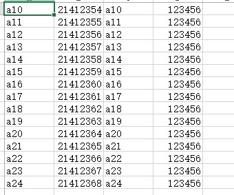
2. Click Upload. Select a file and a separator. Select Normal for Imported User State.
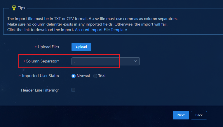
3. Click Next to open the batch import configuration page.
¡ Set User Name and Identity Number on the Basic Information page, and select a User Group.
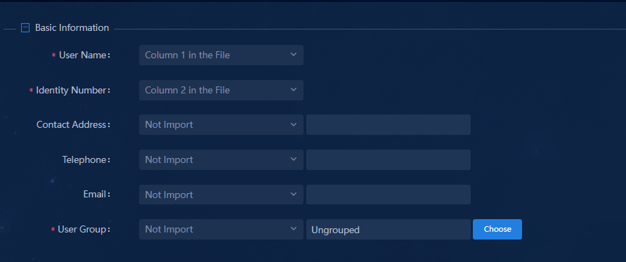
¡ In the Access Information area, set the Account Name and Password. The password can be selected from the file or you can directly enter the password. If you directly enter the password, all users use the same password.
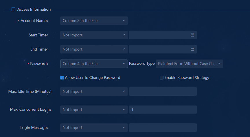
¡ Select Access Service in the access service field. It is a required field.
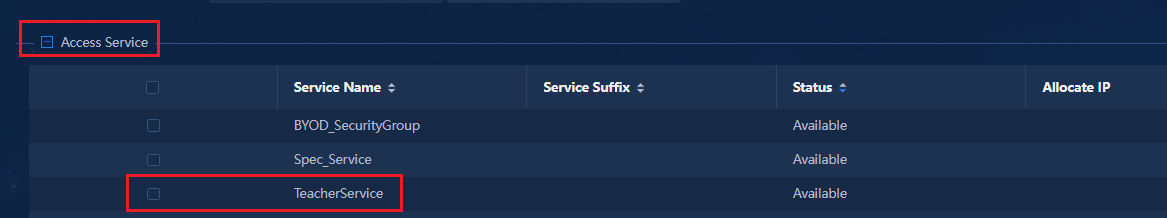
4. After the configuration is completed, click OK to batch import users.
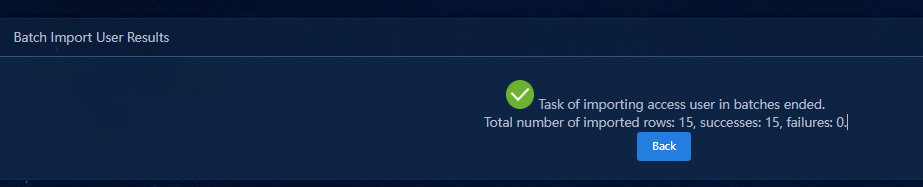
5. After users are successfully imported, you can view the imported users on the Access Users page.
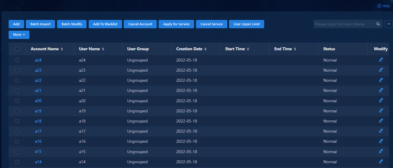
Manage access scenarios (optional)
1. Navigate to the Automation > User Service > Access Service. Click Edit Access Service page, and click Add on the Access Scenario List. You can add an access scenario in the two following ways:
¡ Click
![]() in the corresponding Actions column to open the page for
editing access service. Click Add on the Access Scenario List
column to add the access scenario in the page.
in the corresponding Actions column to open the page for
editing access service. Click Add on the Access Scenario List
column to add the access scenario in the page.
¡ Click Add to open the page for adding Access service. Click Add on the Access Scenario List column to add the access scenario in the page.
When a user comes online, the system matches the user with the configured access scenarios and assigns the user to the security group specified in the matching scenario. If no match is found for the user, the system assigns the user to the security group specified in the default access policy.
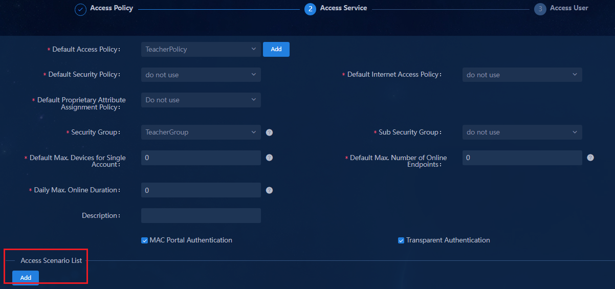
2. Configure the access conditions based on Who, Whose, What, When, Where and How (5W1H).
The user authentication based on 5W1H can cover various access scenarios according to the dimensions including Who, Whose (whose device), What (What device), When, Where, and How. Users can flexibly customize scenarios according to their needs.
For example, to configure an access location group, click Add for the Access Location Group (Where, How) to open the page for adding access location group. You need to choose where to access the switch, that is, the “Where” in 5W1H.
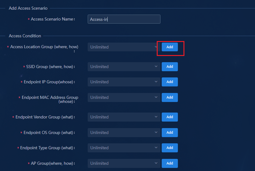
3. Select the access devices or interfaces in the page for adding access location group. Configure the basic parameters, select the access devices or interfaces, and then click Confirm.
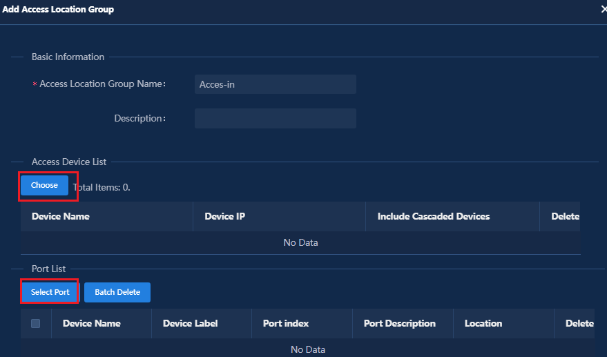
¡ You can select leaf devices, access devices, or cascaded access devices. When you select a leaf device, you can select whether to include its cascaded access devices.
¡ You can select specific interfaces on leaf and access devices. If you select a device as an access device, you cannot select interfaces on the device as access interfaces, and vice versa.
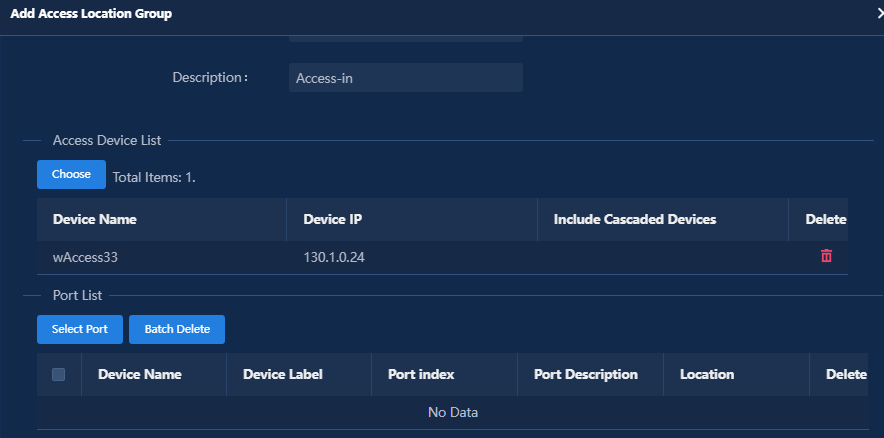
4. On the access scenario configuration page, configure the access policy parameters, and then click Confirm to finish the access scenario configuration. Then, the configured access scenario will be displayed in the access scenario list.
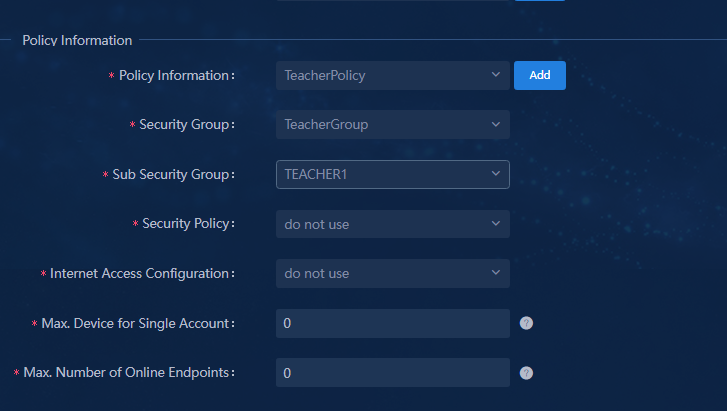
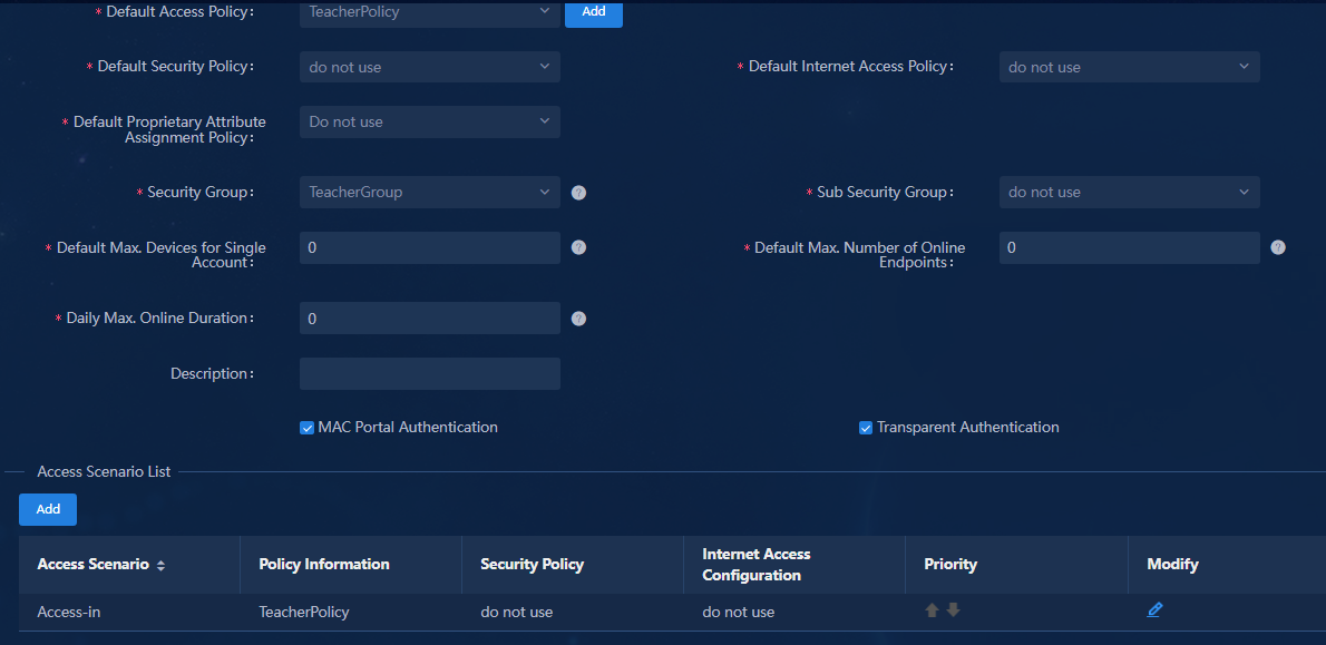
Set the maximum number of online endpoints supported by an account
Set the maximum number of online endpoints supported by an account
The Max. Concurrent Logins parameter specifies the number of endpoints that use the same account for login. Navigate to the Automation > User Service > Access User > All Access Users page. For example, if you set the value for this parameter to 3, a maximum of 3 endpoints that use this account can be online at the same time.
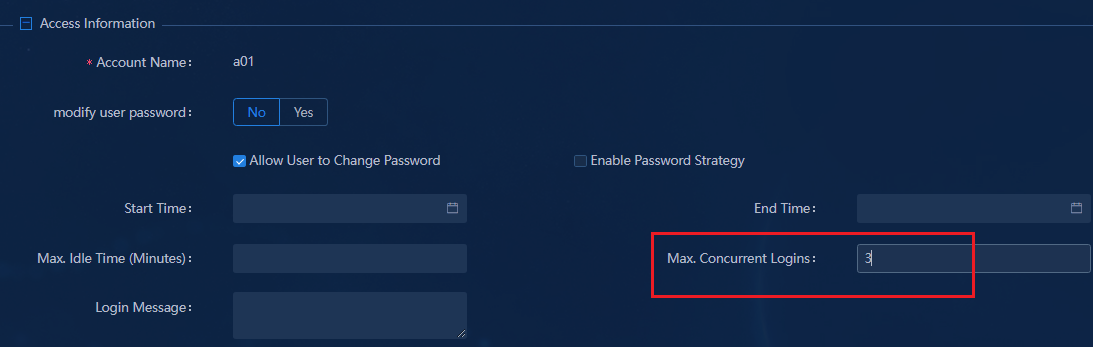
The Max. Concurrent Logins parameter is associated with Log Off Duplicate Account and Max. Device for Single Account. For the parameter description of Max. Device for Single Account, see "Configure user endpoint settings."
Log Off Duplicate Account
Navigate to the Automation > User
> Access Parameters > System Settings page, and click ![]() in the Actions column of system
parameter configuration.
in the Actions column of system
parameter configuration.
The Log Off Duplicate Account parameter takes effect only when the value for the Max. Concurrent Logins parameter is 1.
· If you set Log Off Duplicate Account to Enable:
¡ When the value for the Max. Concurrent Logins parameter is 1, if two endpoints go online by using the same account, the system forcibly logs out the first authenticated endpoint that goes online.
¡ When the value for the Max. Concurrent Logins parameter is greater than 1, the second endpoint cannot go online even you set Log Off Duplicate Account to Enable.
· If you set Log Off Duplicate Account to Disable:
¡ When the value for the Max. Concurrent Logins parameter is 1, if two endpoints go online by using the same account, the second endpoint cannot go online.
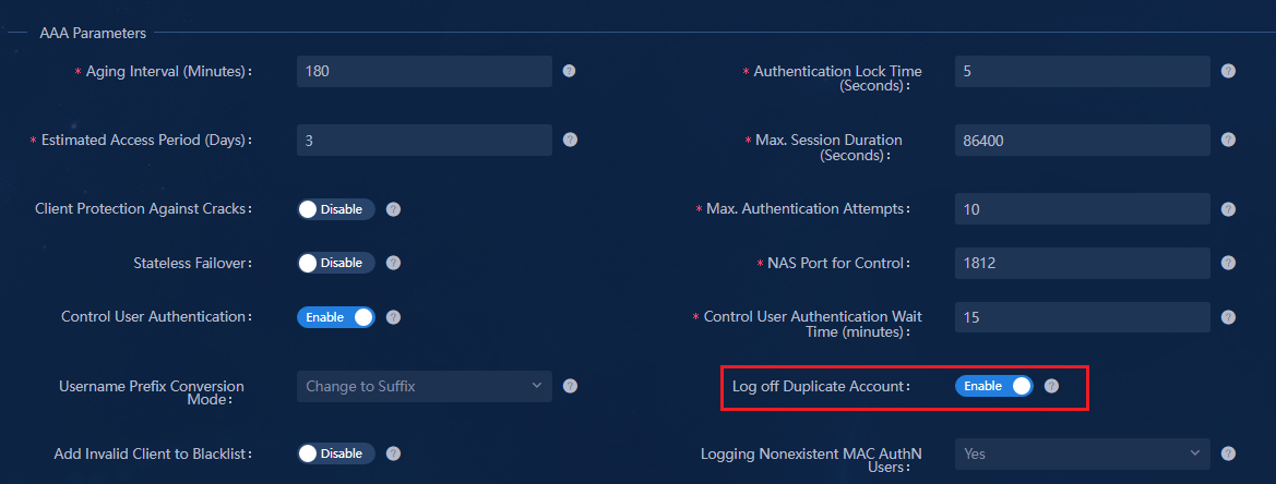
Manage online users
1. Navigate to the Monitor > Monitor List > User > Online Users page.
1.All online users are displayed in the list. You can click the corresponding buttons to manage the online users, including sending messages, forcibly logging out, clearing online information, reauthenticating, customizing page, and bulk exporting. You can perform operations on any online user, including viewing detailed information, collecting logs, and blacklisting.
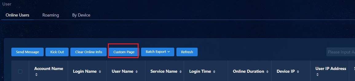
2. You can click Custom Page to customize the information to display on the online user list.
Click Add to open the page for
adding push policies. Select the items in the Option List and click the ![]() button
to add the selected items to the Output List. You can also click the
button
to add the selected items to the Output List. You can also click the ![]() button
to delete the unnecessary options from the Output List. The deleted
options return to the Option List.
button
to delete the unnecessary options from the Output List. The deleted
options return to the Option List.
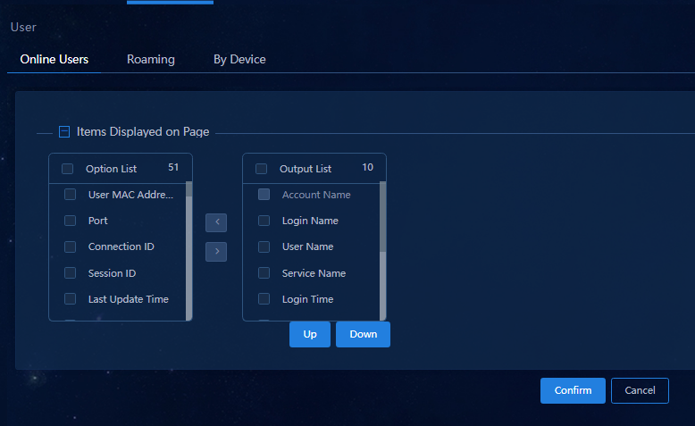
User authentication
Before endpoint users pass authentication to come online, you must complete the basic configuration as described in 0"AD-Campus configuration", which includes the following:
· Device policy templates (including AAA, MAC authentication, 802.1X authentication, and MAC move templates) and interface group templates (including MAC authentication and 802.1X authentication templates). The configuration will be issued to leaf device groups and leaf downlink interface groups.
· Configuration of private networks, security groups, access policies, and access users.
Configure 802.1X authentication
After completing the above configurations, the user can be authenticated through the 802.1X authentication software.
Install certificates
|
|
NOTE: · If you use the H3C iNode client to initiate DOT1X authentication, no certificate is required. · If you do not use the H3C iNode client, you need to install a certificate on the EIA authentication server. The certificate ensures that the non-H3C 802.1X client (for example, the Windows built-in 802.1X client and the mobile phone Wi-Fi client) can be authenticated successfully. |
1. Navigate to the Automation > User > Access Parameters > Certificate page, and click Import Built-in Certificate to import the H3C built-in certificates. After the configuration, the non-H3C iNode client that initiates 802.1X authentication can be authenticated successfully.
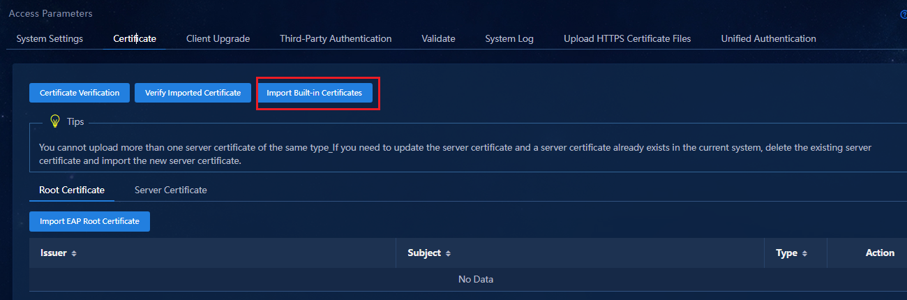
2. If the client uses non-H3C certificates, the client can import certificates in the two following ways:
¡ Select the Root Certificate tab and click Import EAP Root Certificate to import certificates.
¡ Select the Server Certificate tab and click Import EAP Root Certificate to import certificates.
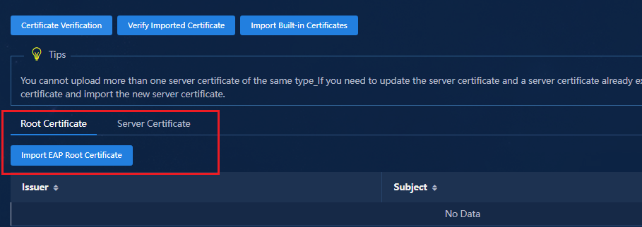
Initiate 802.1X authentication
iNode client
The following uses H3C iNode client to describe the user authentication.
1. Start the iNode client and enter a username and password.
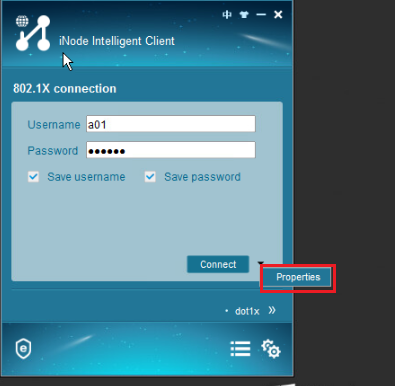
2. Set Properties. Click the inverted triangle next to Connect, and then click Properties. In the Properties dialog box, configure the following parameters on the Network tab:
¡ Select Unicast or Multicast as the packet type to trigger authentication.
¡ Select Upload IPv4 Address if the client uses a static IP address.

3. Click Connect, and you can view that the user has gone online successfully on the endpoint PC. You can also view the online user information on the Monitor > Monitor List > User > Online Users page.
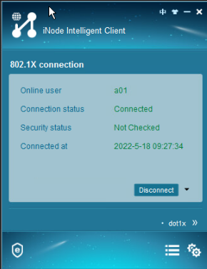
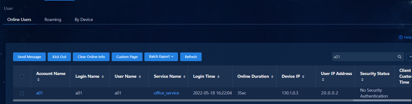
Non-H3C iNode as the client
1. Device policy template - 802.1X authentication. Select the EAP authentication mode. For more information, see "Device policy template - 802.1X authentication."
2. For the configuration of disabling the handshake function on the leaf downlink interface, see "Customize a policy template."
#
interface Bridge-Aggregation1024
port link-type trunk
port trunk permit vlan all
link-aggregation mode dynamic
mac-based ac
dot1x
Undo dotlx handshake // Disable the shakehand function.
undo dot1x multicast-trigger
#
3. For client configuration, enable the Wired AutoConfig service in Services.
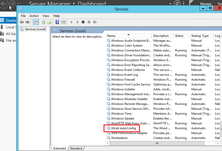
4. On the Network Card > Properties > Authentication page, select Enable 802.1X authentication and Fallback to unauthorized network access.
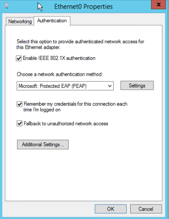
5. On the Network Card > Properties > Authentication > Settings page, select Verify the Server’s identity by validating the certificate, and use default settings for the other parameters.
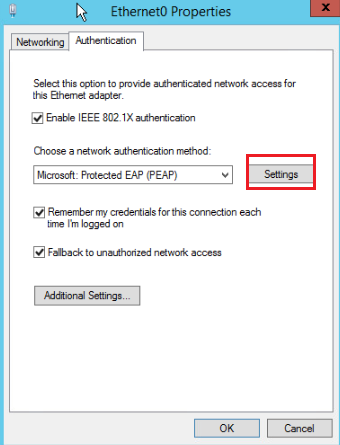
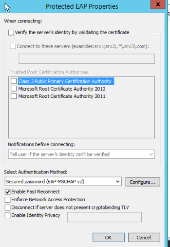
6. On the Network Card > Properties > Authentication > Advanced Settings page, select Specify authentication mode and select User authentication in the drop-down box. Enter the authentication user name and password on the Save credentials page.
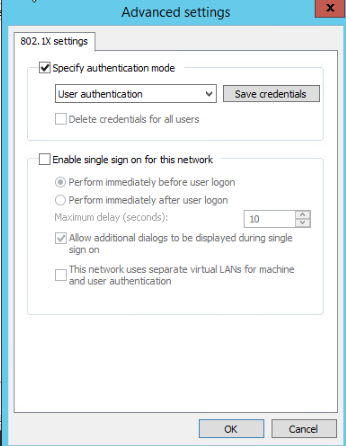
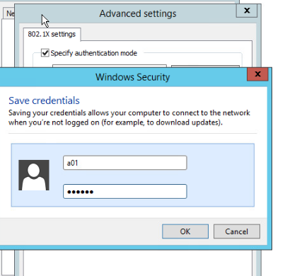
7. After the settings, the user can be authenticated successfully.
8. When certain endpoints are authenticated, they carry prefix information that causes authentication failure with a message that the user does not exist. To resolve this issue, configure AAA authentication and add a domain name with the suffix. For more information, see "Device policy template-AAA." In addition, you can modify the user name prefix conversion method to remove the prefix information (on the Automation > User > Service Parameters > Access Parameters > System Parameter Configuration page).
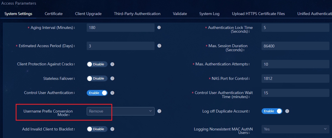
Configure MAC portal authentication
MAC portal authentication is mainly applicable to users without clients. You cannot directly enter a username or password for authentication. By pushing a MAC portal authentication page to a user when the user requests network access, the user can enter its username and password on the page for authentication.
First stage: When a user's endpoint is connected to a port on the access switch and the port comes up, the endpoint sends packets carrying its MAC address to trigger MAC authentication. The switch identifies the user as the BYOD anonymous user. The user endpoint obtains an IP address from the subnets specified for the security group.
Second stage: When the user opens a webpage, the access switch redirects it to the MAC portal authentication page. On the page, enter the username and password. After the user logs in successfully, the user is added to its associated user security group. Then, the user endpoint obtains an IP address from the subnets specified for the user security group.
The default lease time for IP addresses in the BYOD-type security group is 1 minute on the DHCP server, so the lease time of the IP address obtained by the endpoint at the first stage is 1 minute. When the user logs in by entering the username and password on the pushed authentication page, the user is assigned to its associated user security group. After the IP address obtained at the first stage expires, the endpoint requests another IP address. Then, the access switch obtains an IP address from the subnets specified for the user security group for the endpoint.
Create a BYOD-type security group
Log in to SeerEngine-Campus.
1. Navigate to the Automation > Campus Network > Private Network > Layer 2 Network Domain page, and click Add.
¡ BYOD Layer 2 network domain: The BYOD Layer 2 network domain is used for MAC Portal authentication.
- Private Network: Select vpn-default.
- Type: Select BYOD.
- DHCPv4 server: For the BYOD security group, select H3C vDHCP.
- IP Address Lease Duration: The default lease of the BYOD address pool is 60 seconds. The value can be modified as required. As a best practice, set a value longer than 30 seconds.
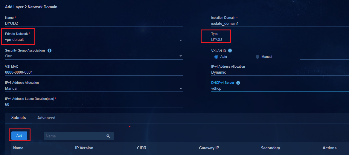
2. Click the Subnet tab. Click Add and enter the name, IP version, network segment and gateway. Click OK.
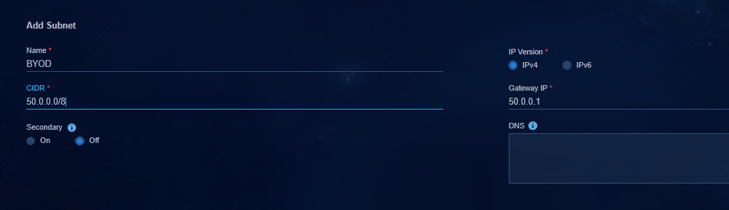
3. After returning to the Layer 2 network domain, click OK again. You can see the added BYOD Layer 2 network domain on the Layer 2 network domain page.
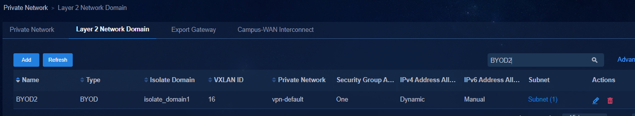
4. After the BYOD layer 2 network domain is added, the domain is automatically added to the Automation > Campus Network > Security Group > User Security Group page, in which BYOD_ SecurityGroup is set by default.
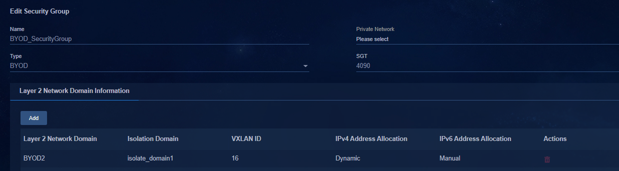
Configure ACL3001
ACL 3001 has been configured in "Configure a policy template."
In the Authentication-Free IPs area of the device policy template, add the IP address of the EIA server. When the device policy template is applied to a device group, ACL3001 is deployed to the devices in the device group. When you add, modify, or delete free IPs on the controller, the controller deploys the changes to the devices.
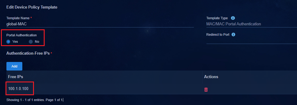
The policy is deployed according to the device group policy configuration.
#
acl number 3001
description SDN_ACL_AUTH
rule 0 permit udp destination-port eq dns
rule 1 permit ip vpn-instance vpn-default destination microsegment 65535
rule 2 permit ip vpn-instance Teach destination microsegment 65535
#
#
microsegment 65535 name SDN_EPG_PORTAL_SERVER
member ipv4 100.1.0.100 255.255.255.255 vpn-instance Teach
member ipv4 100.1.0.100 255.255.255.255 vpn-instance vpn-default
#
Enable MAC portal authentication
1. Navigate to the Automation > User > Access Parameters > System Settings page. In the User Endpoint Settings column on the System Settings tab, enable MAC Portal Authentication to open the MAC Portal Fast Configuration page. (If MAC portal authentication has been enabled, first disable it and then re-enable it.) In addition, enable transparent authentication.
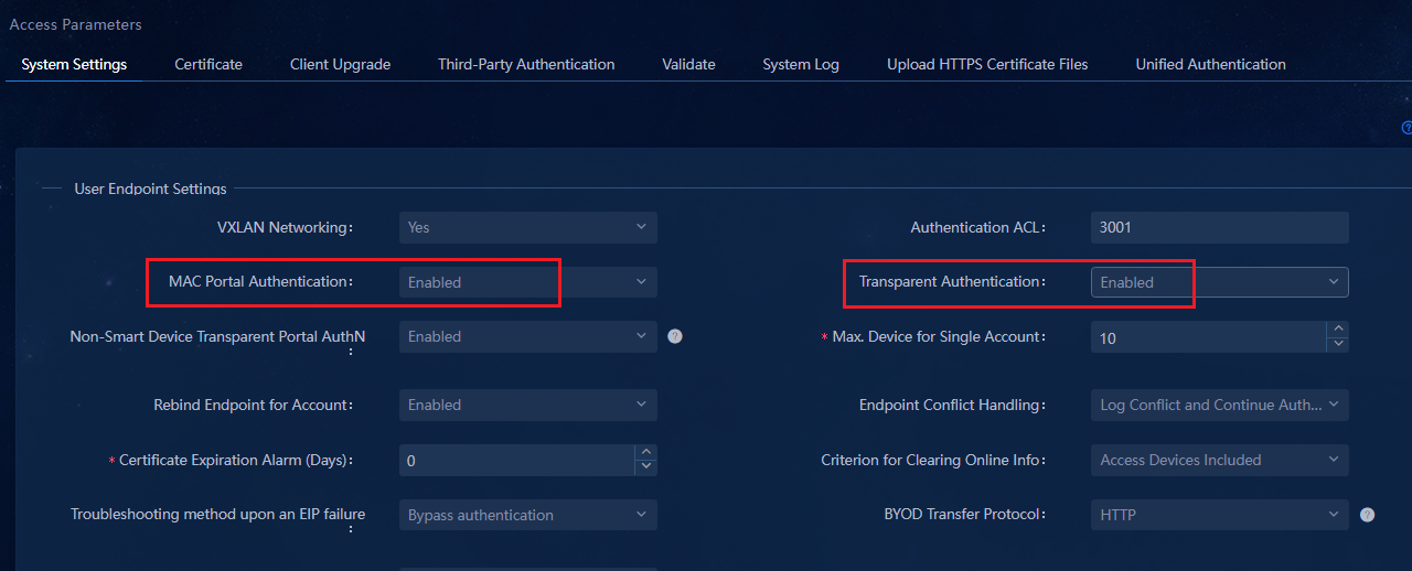
2. On the MAC Portal Fast Configuration page, click Confirm. The system automatically creates a set of settings as follows: BYOD access policies, BYOD access services associated with access policies, and BYOD security groups, creating BYOD users and binding BYOD access services.
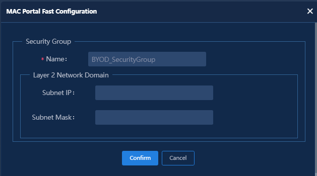
Automatically created access policy.
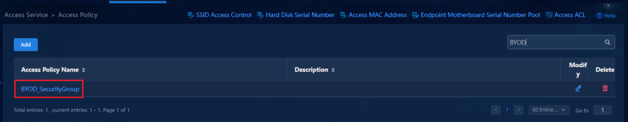
The system automatically creates the access service. The access service is associated with the access policy and security group.
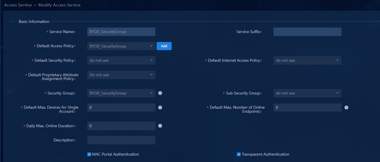
Automatically created BYOD user.
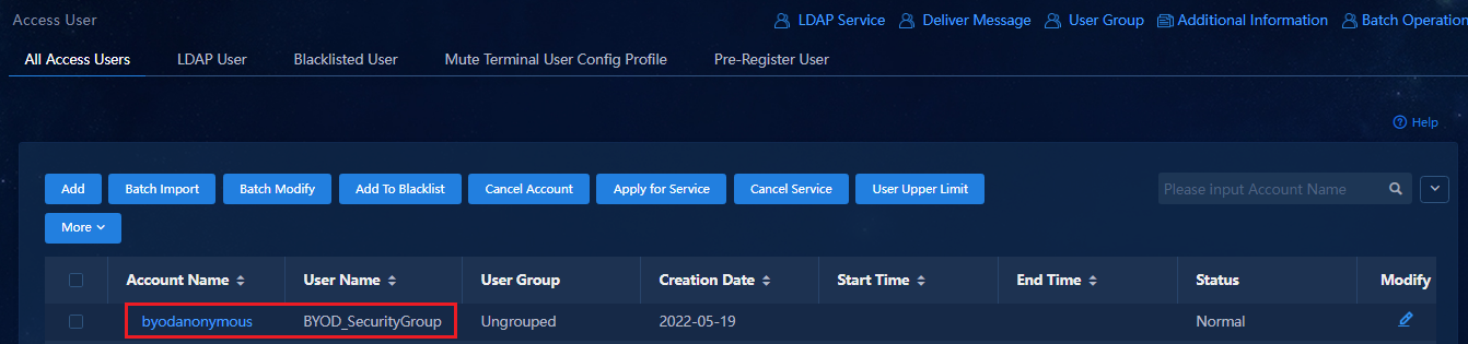
Initiate MAC portal authentication
1. When the port connected to an endpoint is up, MAC authentication is triggered. The BYOD authentication is performed first. Use the anonymous account byodanonymous to log in. Verify that the user is assigned to the BYOD-type security group and the endpoint obtains an IP address from the subnets specified for the BYOD-type security group.
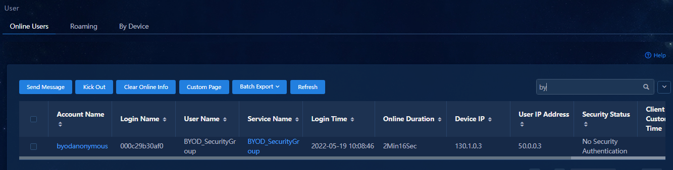
On the access switch (acts as the authenticator), display online MAC authentication user information as follows:
[Leaf-S105B]dis mac-authentication connection
Total connections: 1
Slot ID: 0
User MAC address: 000c-29b3-0af0
Access interface: Ten-GigabitEthernet0/0/37
Username: 000c29b30af0
User access state: Successful
Authentication domain: eia
IPv4 address: 50.0.0.3
IPv6 address: FE80::6D99:7824:2037:C6D
IPv4 address source: IP Source Guard
IPv6 address source: User packet
Initial VLAN: 102
Authorization untagged VLAN: N/A
Authorization tagged VLAN: N/A
Authorization VSI: vsi3
Authorization microsegment ID: 4090
Authorization ACL number/name: 3001
Authorization user profile: N/A
Authorization CAR: N/A
Authorization URL: http://100.1.0.100:30004/byod/index.html?usermac=%m&userip=%c&userurl=%o&original=%o
Authorization IPv6 URL: N/A
Start accounting: Successful
Real-time accounting-update failures: 0
Termination action: Default
Session timeout period: 86400 sec
Online from: 01/15/2022 11:11:10 AM
Online duration: 0h 3m 58s
Port-down keep online: Disabled (offline)
[Leaf-S105B]
2. On the user's PC, open the Web browser and enter any IP address such as 1.1.1.1. The PC automatically jumps to the following BYOD URL redirection page: If a user uses a domain name to access the network, the user can redirect to the authentication page. (For users who obtain IP addresses through DHCP, set the IP address of the DNS server in the isolation domain or Layer 2 network domain. For users with static IP addresses, manually configure the IP address of the DNS server.) In addition, ensure that the Spine and Leaf devices have reachable routing to the DNS server.
|
|
IMPORTANT: The client browser must be Chrome and does not support Internet Explorer. The client browser must be Chrome V7.0 or later. |

3. Enter the correct username and password, and click Log In. The following page opens after successful authentication.
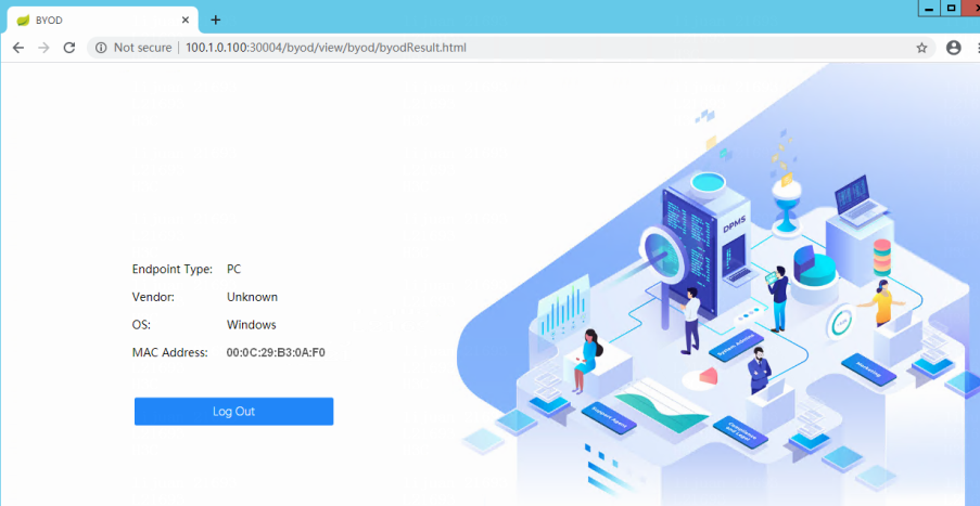
4. View the user online information on the EIA. Verify that the user has accessed its associated access service and the user endpoint has obtained an IP address from the subnets associated with the access service.
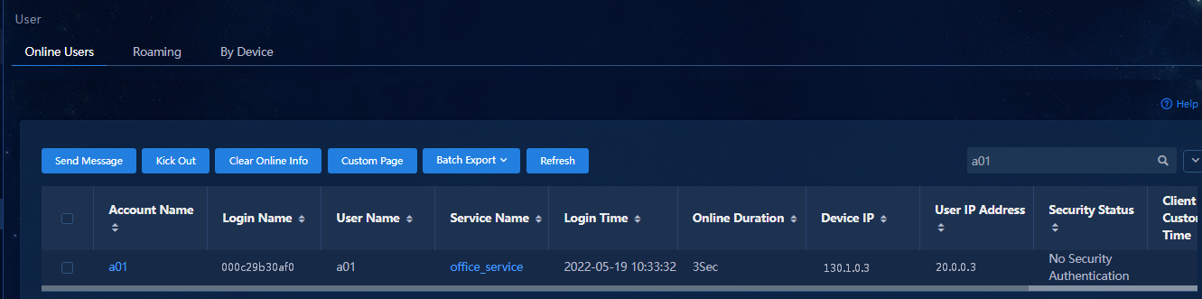
On the access switch (acts as the authenticator), display online MAC authentication user information.
[Leaf-S105B]dis mac-authentication connection
Total connections: 1
Slot ID: 0
User MAC address: 000c-29b3-0af0
Access interface: Ten-GigabitEthernet0/0/37
Username: 000c29b30af0
User access state: Successful
Authentication domain: eia
IPv4 address: 20.0.0.3
IPv4 address source: IP Source Guard
Initial VLAN: 102
Authorization untagged VLAN: N/A
Authorization tagged VLAN: N/A
Authorization VSI: vsi4
Authorization microsegment ID: 3504
Authorization ACL number/name: N/A
Authorization user profile: N/A
Authorization CAR: N/A
Authorization URL: N/A
Authorization IPv6 URL: N/A
Start accounting: Successful
Real-time accounting-update failures: 0
Termination action: Default
Session timeout period: 86400 sec
Online from: 01/15/2022 11:18:37 AM
Online duration: 0h 2m 27s
Port-down keep online: Disabled (offline)
[Leaf-S105B]
Configure MAC authentication
MAC authentication is mainly applicable to scenarios where a user does not have a client and intends to trigger authentication to come online directly through the endpoint MAC address.
Configure MAC authentication users
Navigate to the Automation > User > Access User page, and click Add to add access users. You can manually add access users or import access users in bulk.
Manual incorporation
1. Click Add to open the page for adding access users. In the Access Information column, enter the account name and select the MAC Access User. The server automatically configures a password for the user. For a MAC address with the account name in the format of xxxxxxxxxxxx, select MAC Access User. After that, the server automatically configures the password of the user.

2. Select an access service for the user in the Access Service page, and then click OK to add a MAC access user.
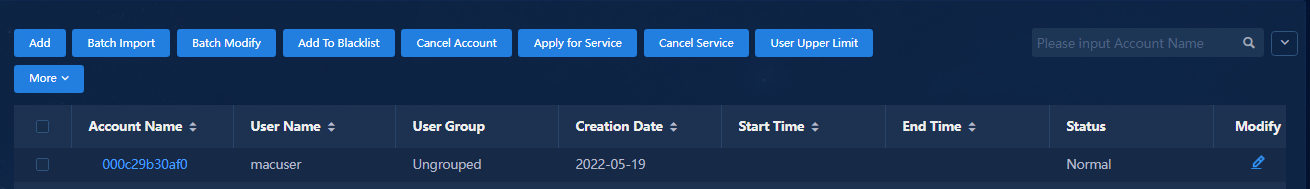
Import access users in bulk
1. On the Access User page, click Batch Import. You can click the Account Import file Template link in the prompt area to download the import template. Specify the relevant information according to the template.
2. Click Batch Import to import the file in bulk. The usernames and passwords in the file must be MAC addresses in the format of xxxxxxxxxxxx, as shown below.
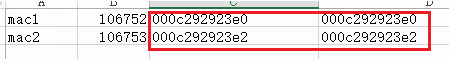
3. After the file is uploaded, select the column separator in the file and click Next to open the page for configuring access user information. Ensure that the account name and password in the access information column are both MAC addresses.

4. Select an access service and click OK and you can view the imported user.
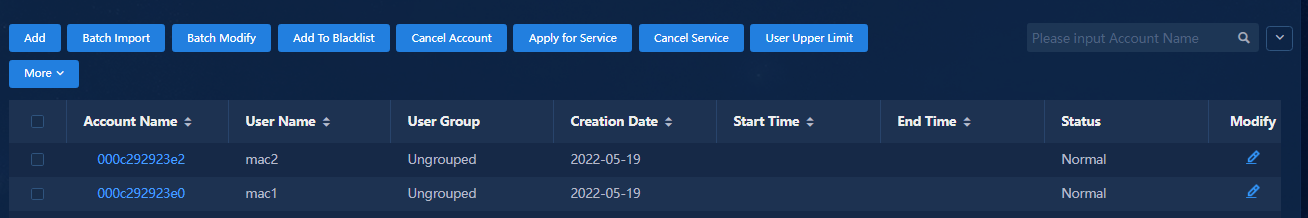
Initiate MAC authentication
Connect the PC to a port on the access switch. After the port comes up, the PC sends packets with its MAC address to trigger MAC authentication. After successful authentication, you can view information about the online MAC authenticated user on the Monitor > Monitor List > User > Online Users page.
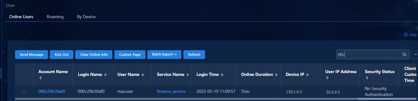
Configure authentication-free interfaces
You can configure authentication-free interfaces for the controller. When a user comes online from an authentication-free interface, the user can join the specified security group directly without authentication to obtain an IP address and access the corresponding network resources of the security group.
When setting an authentication-free interface, you need to create an authentication-free interface group first. By default, the system does not create an authentication-free interface group.
Configure authentication-free VLAN pool
Navigate to the Automation > Campus Network > Network Devices > VNI Pools page. The system has predefined a certificate-free VLAN range by default.
The default authentication-free VLAN range
is 4051-4060. You can click ![]() to change the VLAN
range.
to change the VLAN
range.
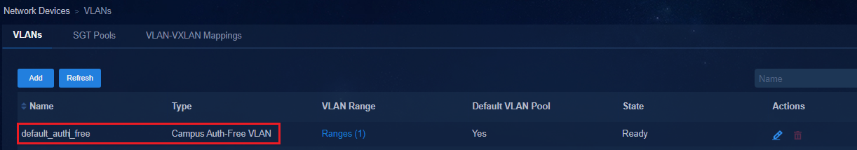
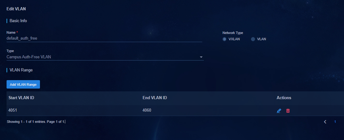
Add an authentication-free interface group
To configure authentication-free in a security group, you need to configure an authentication-free interface group first.
1. Navigate to the Automation > Campus Network > Device Groups > General Device Groups page, and click Add.
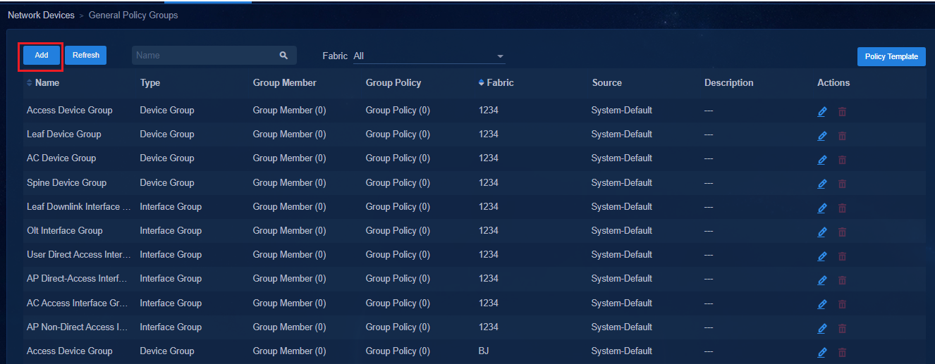
2. Create an authentication-free interface group and select the members of the group:
¡ Type: Set Group Type to Interface Group.
¡ Subtype: Select Authentication-Free Interface Group.
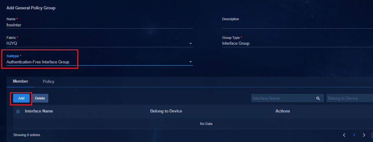
3. On the Members tab of the page, click Add to open the Add Interface page. Select devices and interfaces and click Add to add the selected interface to the list. Click OK to return to the page of adding a general device group.
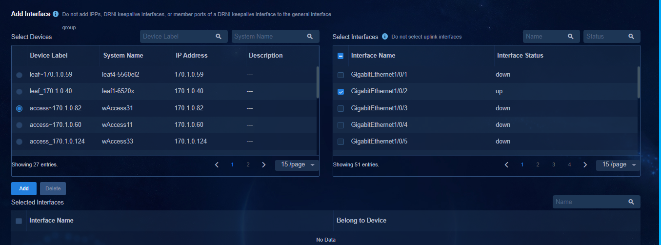
4. Click OK to save the configuration. In the general device groups list, you can view the authentication-free interface groups.
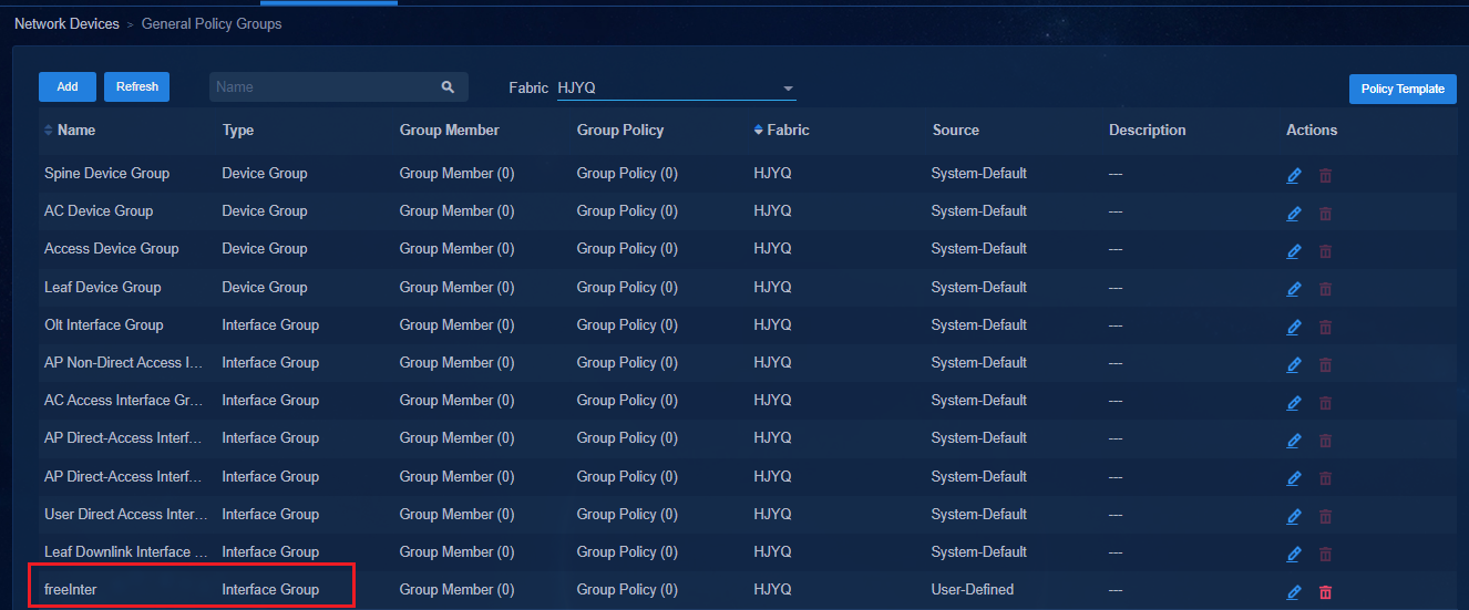
Add port isolation device group
|
|
IMPORTANT: · If the interfaces in the authentication-free interface group are the interfaces on the access device, add the access device to the port isolation device group. For cascaded access devices, only the access devices that join the authentication-free interface group are added to the port isolation device group. · If the authentication-free port configured earlier is the port on the leaf device, skip this step. |
1. Navigate to the Automation > Campus Network > Network Devices > General Device Groups page. Click Add in the general policy page to open the page for adding general device group.
2. Create a port isolation device group and select the access device configured with the authentication-free interface group, as shown in the following figure:
¡ Group Type: Select Device Group.
¡ Fabric: Select a fabric for the access device.
¡ Subtype: Select Port Isolation Device Group.
¡ Group Type: Select Enable for DRNI networking.
¡ Ports Outside Isolation Groups: All uplink interfaces connecting the leaf device to the access device must be added to the ports outside isolation groups. If multiple access devices are cascaded, the uplink interfaces connecting lower-level access devices to upper-level access devices must also be added to ports outside isolation groups. That is, the uplink interfaces of access devices must be added to ports outside isolation groups.
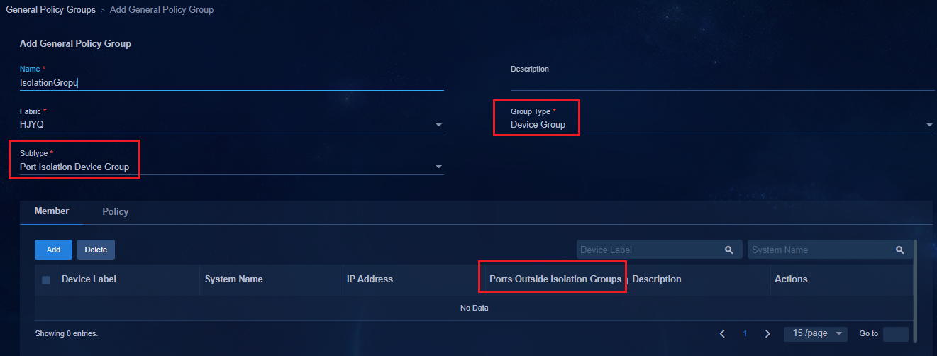
3. Configuration deployed on the access devices:
4. Issue port isolation group globally:
#
port-isolate group 1
#
5. Issue the port-isolate enable group 1 command to all ports (except ports outside isolation groups) of the access devices:
#
interface GigabitEthernet1/0/1
port link-mode bridge
port access vlan 101
port-isolate enable group 1
stp edged-port
#
Bind authentication-free interface group to security group
Navigate to the Automation > Campus
Network > Security Group page. Click ![]() in
the Actions column to open the page for editing security groups.
in
the Actions column to open the page for editing security groups.
1. On the page for adding security groups, click the Auth-Free tab to configure the Auth-Free setting for users.
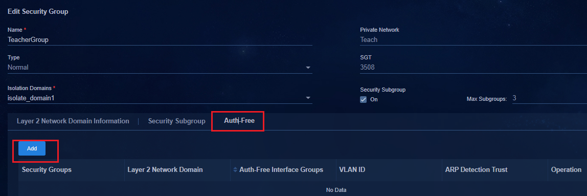
2. Configure Auth-Free and select the Auth-Free Interface Groups.
3. By default, the system sets the VLAN ID based on the specified VLAN range set in "Configure authentication-free VLAN pool." You can also manually configure the VLAN ID. The controller will deliver the configured VLAN ID.
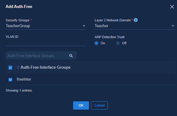
Deploy configuration to the devices
After the security group is bound to the authentication-free interface group, the following configuration is deployed to the devices:
1. Members of the authentication-free interface group are interfaces on the access device.
#Add service-instance 4051 to the Leaf downlink interface that connects to this access device.
#
interface Ten-GigabitEthernet1/2/0/13
port link-mode bridge
port link-type trunk
port trunk permit vlan all
port-security free-vlan 1 4051 4094
#
service-instance 4051
encapsulation s-vid 4051 //VLAN 4051 to VLAN 4060 are used by the controller for the authentication-free service by default.
xconnect vsi vsi4 microsegment 3504 on-demand
arp detection trust
#
#
# Add a static VLAN configuration to an authentication-free interface on the access device.
#
interface GigabitEthernet1/0/1
port link-mode bridge
port access vlan 4051
port-isolate enable group 1
stp edged-port
#
2. Members of the authentication-free interface group are interfaces on the Leaf device.
# Add service-instance 4051 to the leaf device connected to the authentication-free interface.
interface Ten-GigabitEthernet1/2/0/14
port link-mode bridge
port link-type trunk
port trunk permit vlan 1 4051
port trunk pvid vlan 4051
port-security free-vlan 4051
#
service-instance 4051
encapsulation untagged
xconnect vsi vsi4 microsegment 3504
arp detection trust
#
Configure static AC authentication
|
|
IMPORTANT: · The VLAN pool for static access must be configured in advance. For more information, see "User VLAN planning." · Static AC authentication applies to scenarios where users on the same IP address segment need to have different access permissions. |
Add a static access interface group
Navigate to the Automation > Campus Network > Device Groups > General Device Groups page, and click Add.
· Group Type: Select Interface Group.
· Subtype: Select Static Access Interface Group.
· Member: Click the Member tab. Click Add and select the interfaces that endpoints use to connect to the access or spine device.
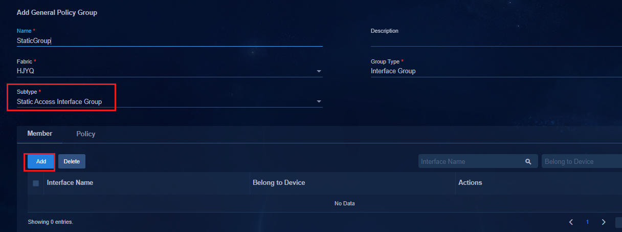
Add port isolation device group
|
|
IMPORTANT: · If the static interface group is an Access device interface, you need to add the Access device to the port isolation device group. The multi-cascaded Access devices require only to add the Access devices that join the static interface group to the port isolation device group. · If the authentication-free port configured earlier is the port on the Leaf device, skip this step. |
1. Navigate to the Automation > Campus Network > Devices > General Device Groups. Create an interface isolation device group and select the Access device configured with the authentication-free interface group, as shown below:
¡ Group Type: Select Device Group.
¡ Fabric: Select a fabric for the access device
¡ Subtype: Select Port Isolation Device Group.
¡ Group Type: Select a device group for DRNI networking.
¡ Ports Outside Isolation Groups: All uplink interfaces connecting the Leaf device to the access device must be added to the ports outside isolation groups. If multiple Access devices are cascaded, the uplink interfaces connecting subordinate Access devices to superior Access devices must also be added to ports outside isolation groups. That is, the uplink interfaces of Access devices must be added to ports outside isolation groups.

2. Configuration deployed on the access devices:
3. Issue port isolation group globally:
#
port-isolate group 1
#
4. Issue the port-isolate enable group 1 command to all ports (except ports outside isolation groups) of the access devices:
#
interface GigabitEthernet1/0/1
port link-mode bridge
port access vlan 101
port-isolate enable group 1
stp edged-port
#
Issue the policy template to the leaf device group
1. Navigate to the Automation > Campus
Network > Device Groups > General Device Groups page. Click
![]() in the Actions column for a leaf device group.
in the Actions column for a leaf device group.
2. Click the Policy tab, and click Add to open the page for adding a device group policy.
3. Select a policy template for AAA and MAC authentication or 802.1X authentication.
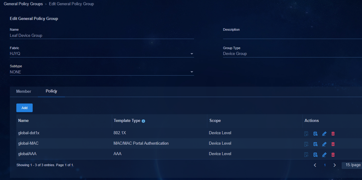
Issue the policy template to the leaf downlink interface
1. Navigate to the Automation > Campus
Network > Device Groups > General Device Groups page. Click
![]() in the Actions column for Leaf Downlink Interface Group
to open the page for editing general device groups.
in the Actions column for Leaf Downlink Interface Group
to open the page for editing general device groups.
2. Click the Policy tab, and click Add to open the page for adding a device group policy. Select a policy template for MAC Portal authentication or 802.1X authentication.
As a best practice, select one of the authentication modes. Do not configure both 802.1X authentication and MAC Portal authentication on a physical interface. Set the authentication mode based on actual requirements.
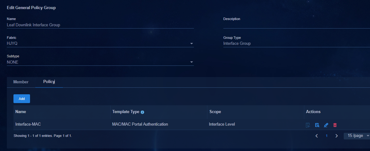
Create a static Access VLAN pool
|
|
IMPORTANT: · When creating a VLAN pool, the VLAN cannot conflict with other VLAN pools. · After the VLAN pool status is In Use, you cannot edit. You need to plan the VLAN range of each VLAN pool before the start. |
1. Navigate to the Automation > Campus Network > Network Devices > VNID Pools page. Open the VLANs page, and create VLANs of the VLAN pool type for static access.
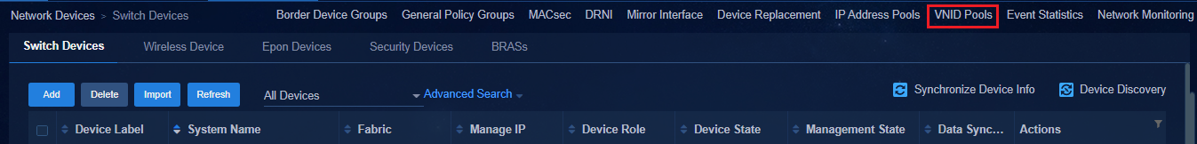
2. Click the VLAN tab and click Add to open the Add VLAN page.
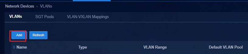
3. Enter the name. Specify Campus Static Access VLAN Pool as the type. Click Add VLAN Range, and enter the VLAN range on the Add VLAN Range page.
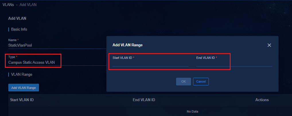
4. After completing the configuration, click OK to save the configuration.
Create a Layer 2 network domain
Navigate to the Automation > Campus Network > Private Network > Layer 2 Network Domain page, and click Add.
· Security Group Associations: Select Static Access.
· Network Ranges: Select the created static access interface group to bind the static access interface group.
· VLAN: Click ![]() , the
system automatically allocates VLAN pools based on the configured static access
VLAN pool. Only one static access group can be assigned to a VLAN in a Layer 2
network domain.
, the
system automatically allocates VLAN pools based on the configured static access
VLAN pool. Only one static access group can be assigned to a VLAN in a Layer 2
network domain.
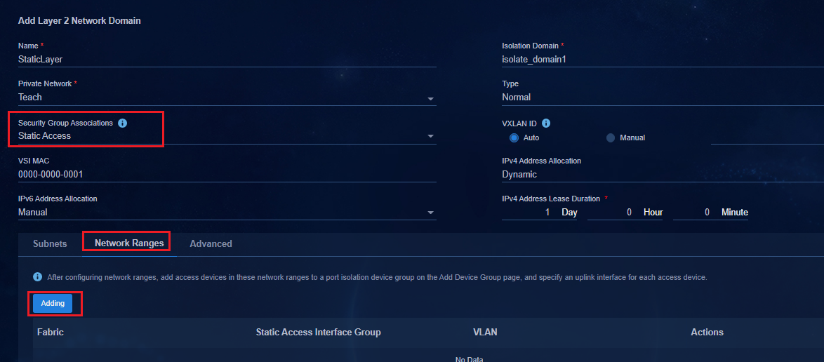
· Configuration deployed to the access device
On the access device, the interface configured in the static access interface group is modified to the value of the VLAN set in the Layer 2 network domain.
[Access3]dis int brief
Brief information on interfaces in route mode:
Link: ADM - administratively down; Stby - standby
Protocol: (s) - spoofing
Interface Link Protocol Primary IP Description
InLoop0 UP UP(s) --
Brief information on interfaces in bridge mode:
Link: ADM - administratively down; Stby - standby
Speed: (a) - auto
Duplex: (a)/A - auto; H - half; F - full
Type: A - access; T - trunk; H - hybrid
Interface Link Speed Duplex Type PVID Description
BAGG1024 UP 20G(a) F(a) T 1
GE1/0/1 UP 1G(a) F(a) A 2801
GE1/0/2 DOWN auto A A 2801
GE1/0/3 DOWN auto A A 2801
GE1/0/4 DOWN auto A A 2801
GE1/0/5 DOWN auto A A 2801
GE1/0/6 DOWN auto A A 106
GE1/0/7 DOWN auto A A 107
· Configuration deployed to the leaf device
Static AC configuration will be deployed to the leaf downlink interface connected to the access device in the static access interface group.
#
interface Bridge-Aggregation1024
port link-type trunk
port trunk permit vlan all
link-aggregation mode dynamic
stp tc-restriction
mac-based ac
mac-authentication
mac-authentication domain hz1
mac-authentication parallel-with-dot1x
port-security free-vlan 1 4094
#
service-instance 2801 // Static AC configuration issued by the controller.
encapsulation s-vid 2801
xconnect vsi vsi6
#
service-instance 4094
encapsulation s-vid 4094
xconnect vsi vxlan4094
#
Create a security group
Navigate to the Automation > Campus Network > Security Group > User Security Group page. Click Add to open the page for adding security groups. Create a security group without adding a Layer 2 network domain. This document selects Tech for Private Network and select Normal for Type. Click OK to save the configuration.
The security group ID (3502 in this example) is the microsegment ID that the controller deploys to the device. The SeerEngine-Campus controller will synchronize the security group to EIA, and EIA will assign this microsegment ID upon user authentication.
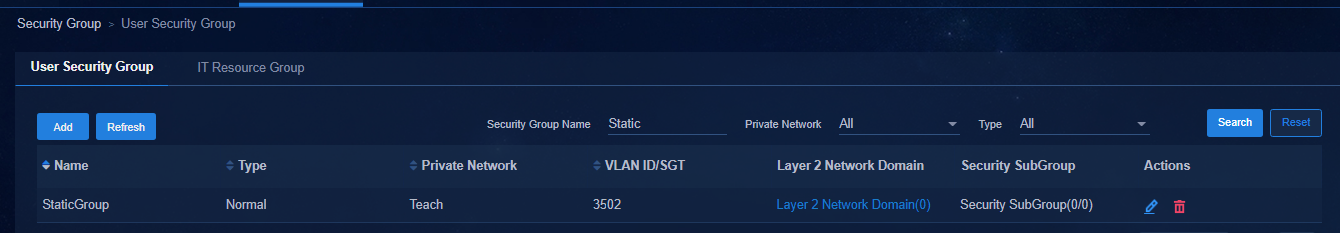
User authentication and online
After the above configurations are completed, an endpoint is connected to the access interface with VLAN ID 2801 on the access device. During user authentication, the user will be assigned to the static AC of the VLAN for the leaf device for authentication.
For 802.1X authentication and MAC portal authentication for clients, see "Configure 802.1X authentication" and "Configure MAC portal authentication."
Configure web portal authentication
|
|
NOTE: · Web portal authentication is applied to the authentication decoupling feature. It supports third-party AAA authentication servers. · The third-party AAA authentication server must support portal authentication and the h3c-user-group attribute. The H3C EIA authentication server can be used as a third-party AAA authentication server. It also supports user authentication by non-H3C third-party AAA authentication servers. · Web portal authentication uses static AC interfaces for authentication. · This section introduces the configuration of web portal authentication on the controller and on the device. For the configuration of the third-party authentication server, see the relevant information of the vendor. |
AAA server
Navigate to the Automation > Campus Network > Parameters > AAA page. Click Add to open the page for adding the authentication server.
For information about adding the H3C EIA authentication server, see "AAA."
Select Third Party Authentication as the server type, and enter the IP address of the EIA server. Ensure that the third-party authentication server can communicate with spine and leaf devices.

Spine/Leaf devices must communicate with the authentication server. The route to the authentication server must be configured on Spine/Leaf devices. The routing configuration methods are as follows:
· Log in to each device and manually configure it.
· Navigate to the Automation > Campus Network > Network Devices > General Device Groups page, and click Policy Template to open the page for policy templates. You can configure a user-defined policy template.
· Navigate to the Automation > Campus Network > Fabrics page. Click the setting icon in Action column to enter the switching device page. Click the Settings tab. Click the Configuration Automation button to click the Address Pool Setting tab and enter the address pool setting page. If the IPv4 management Network Segment of the server is set to the IP address segment of the authentication server, the controller automatically delivers the configuration when the device goes online automatically.
#
ip route-static vpn-instance vpn-default 10.99.12.189 32 130.0.0.254
#
AAA device policy template
Navigate to the Automation > Campus Network > Device Groups > General Device Groups page. Click Policy Template at the upper right corner of the page to open the page for policy templates.
· H3C EIA AAA template
Click ![]() in the Actions
column corresponding to AAA in the list to open the page for editing
policy templates. See "Configure a policy
template."
in the Actions
column corresponding to AAA in the list to open the page for editing
policy templates. See "Configure a policy
template."
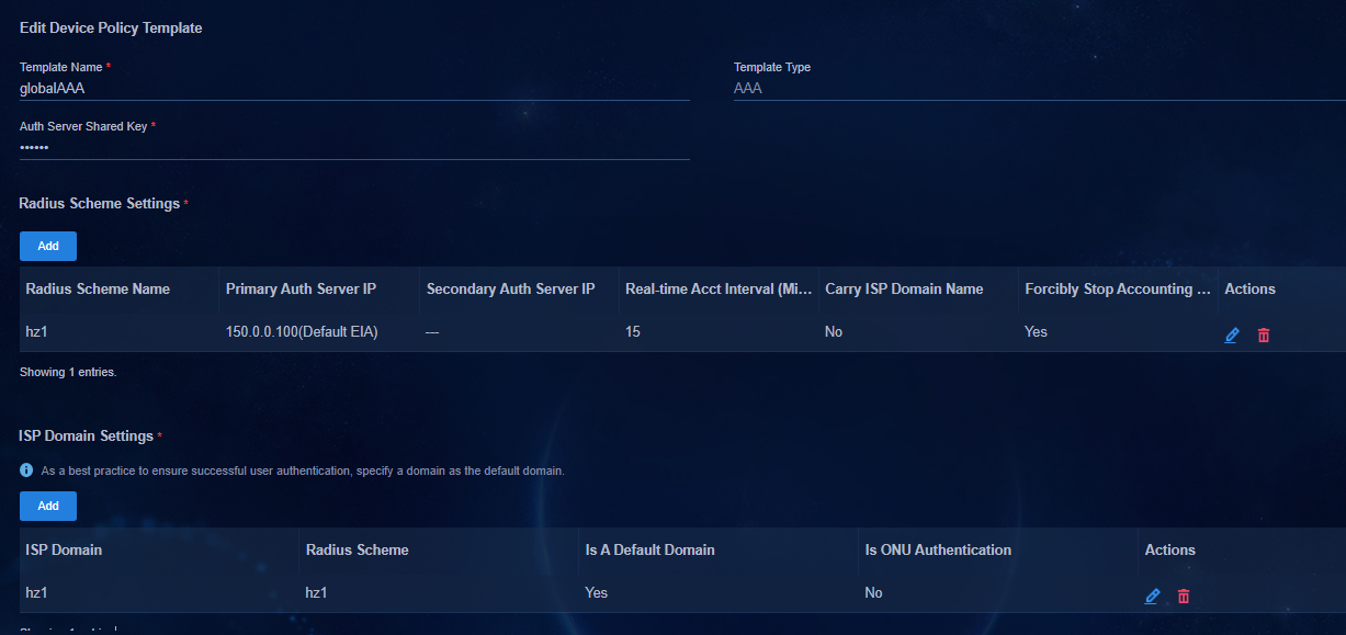
· Configure third-party authentication servers
Click Add, and select Device Policy Template from the drop-down list.
¡ Template Type: Select AAA.
¡ Auth Server Shared Key: Make sure that it is the same as that on the third-party authentication server. This example uses 123456.
¡ Select the added third-party authentication server.
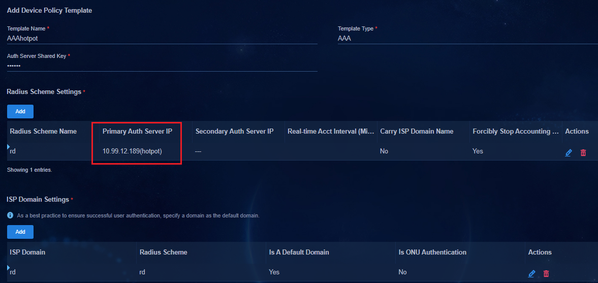
Configure the web portal template
Configure web portal template of third-party authentication server
Navigate to the Automation > Campus Network > Device Groups > General Device Groups page. Click Policy Template at the upper right corner of the page to open the page for policy templates.
1. Click Add, and select Device Policy Template from the drop-down list. Select Web Portal Authentication for Template Type.
2. Click Add in the Portal Server column, and configure the following parameters:
¡ Server Name: Select the added third-party authentication server.
¡ Keys: Make sure the key is the same as that on the third-party authentication server. In this example, it is 123456.
¡ Port Number: The default value is 50010. Use the default setting.
¡ Redirection URL: Users enter the account and password on the web page. It can be set on the authentication server.
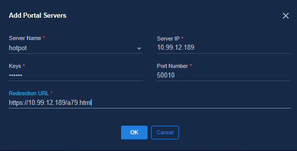
3. Click Add in the URL Domain Settings column to open the Add URL Domain page.
URL parameters: Set the parameters according to the specific authentication server requirements. Configure the wlanacname and wlanacip for Dr.COM.
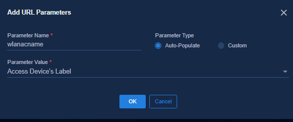
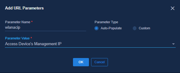
4. After completing the configuration, click OK to save the configuration. You can view the configuration result in the URL Parameters area as shown below:
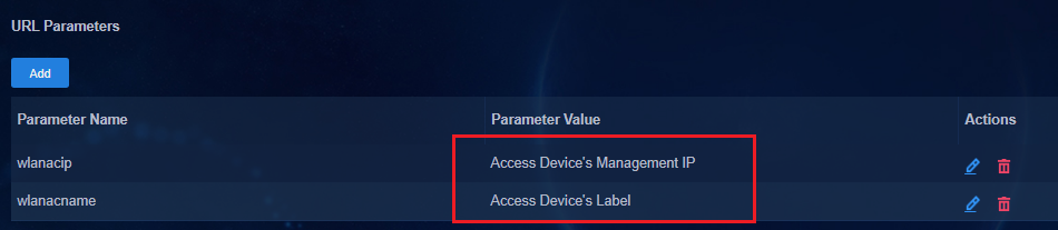
Configure EIA V9 web portal template
Navigate to the Automation > Campus Network > Device Groups > General Device Groups page. Click Policy Template at the upper right corner of the page to open the page for policy templates.
1. Click Add, and select Device Policy Template from the drop-down list. Select Web Portal Authentication for Template Type.
2. Click Add in the Portal Servers column. The page for adding Portal servers is displayed.
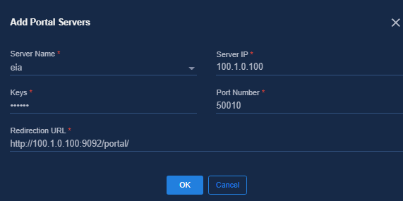
¡ Server Name: Specify the server name.
¡ Server IP: Specify IP address of the EIA server.
¡ Keys: The key is the same as that of device policy template AAA. In this example, it is 123456.
¡ Port Number: The default value is 50010. Use the default setting.
¡ Redirection URL: For endpoint users to open the Web page, enter their account and password on the Automation > User > Access Service page. Click the Portal service management link in the upper right corner to access the Portal service management page. Click the Server Configuration tab, and view the redirection URL in the Portal home page of the Portal Web area, as shown below.
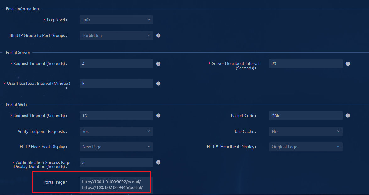
3. Click Add in the URL Domain Settings column to open the Add URL Domain page. The parameter name is nasip. The parameter value selects Access Device’s Management IP. The parameter configuration is shown in the figure below.
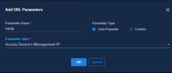
4. After completing the configuration, click OK to save the configuration. You can view the configuration result in the URL Parameters area.
Interface policy template (Web portal and MAC authentication)
Navigate to the Automation > Campus Network > Device Groups > General Device Groups page. Click Policy Template at the upper right corner of the page to open the page for policy templates. Click Add, and select Interface Policy Template from the drop-down list to open the page for adding the interface policy template.
Configure Web Portal interface policy template
Select Web Portal Authentication as the Template Type. Select ISP domain configured in "AAA device policy template" as the ISP Domain. Select the Portal server configured in "Configure the web portal template" as the Primary Portal Server. The configuration information about the third-party authentication server and EIA authentication server is displayed as follows:
Configure the city hotspot AAA server:
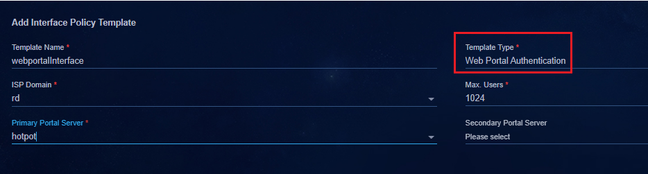
Configure the H3C EIA authentication server:
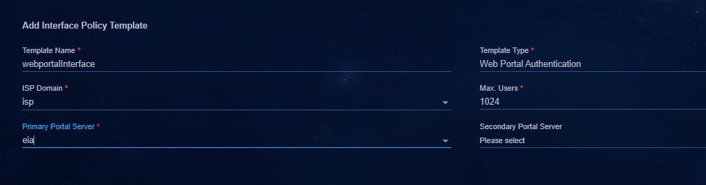
Configure the MAC authentication interface policy template
Select MAC/MAC Portal Authentication for Template Type. Select ISP domain configured in "AAA device policy template" for ISP Domain. The configuration information about the third-party authentication server and EIA authentication server is displayed as follows:
Select the AAA and web portal policy templates configured earlier. Configure a MAC authentication policy template. Web portal and MAC authentication can be combined to implement fast MAC authentication.
· Fast MAC authentication: After a user performs web portal authentication for the first time, the third party authentication server will record the MAC and account information of the user. When the user triggers authentication again after going offline, the MAC authentication is triggered first. The third party authentication server identifies the MAC and account relation of the authenticated user and allows the user to automatically come online, without requiring the username or password.
· MAC fast authentication requires the support of the third party authentication server. At present, the authentication servers of Dr.COM and Srun support MAC fast authentication. For the detailed configuration of the third party authentication server, contact the vendor.
Configure the city hotspot AAA server:
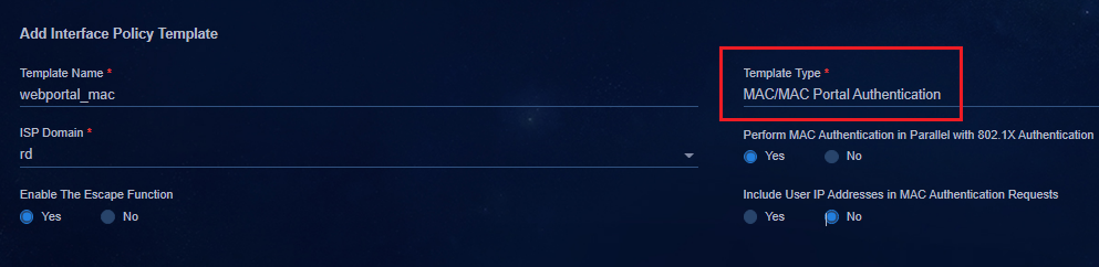
Configure the H3C EIA authentication server:
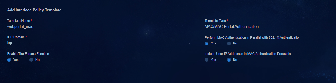
Add a static access interface group
The configuration of creating a static access interface group is the same as that in "Add a static access interface group."
Deploy a policy to a leaf device group
Navigate to the Automation > Campus
Network > Device Groups > General Device Groups page. Click
![]() in the Actions column for Leaf
Device Group.
in the Actions column for Leaf
Device Group.
Click the Policy tab, and click Add to open the page for adding a device group policy. Select the AAA and web portal policy templates configured earlier. Configure a MAC authentication policy template.
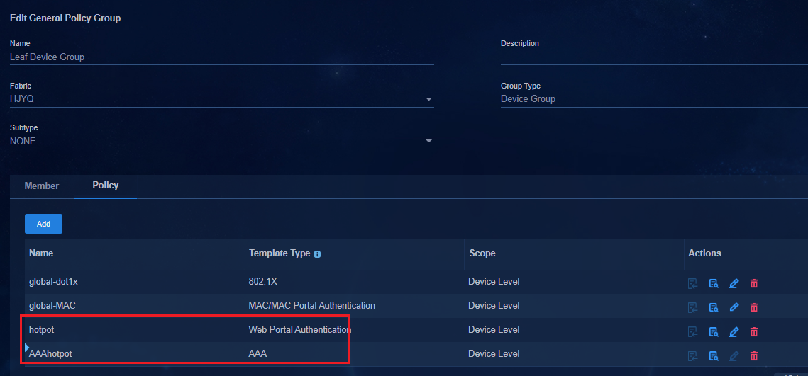
Deploy a policy to a leaf downlink interface group
Navigate to the Automation > Campus
Network > Device Groups > General Device Groups page. Click
![]() in the Actions column for Leaf
Downlink Interface Group.
in the Actions column for Leaf
Downlink Interface Group.
Click the Policy tab, and click Add to open the page for adding a device group policy. Select the policy template and MAC authentication policy template of the web portal that issues the interface, as shown in the following figure.
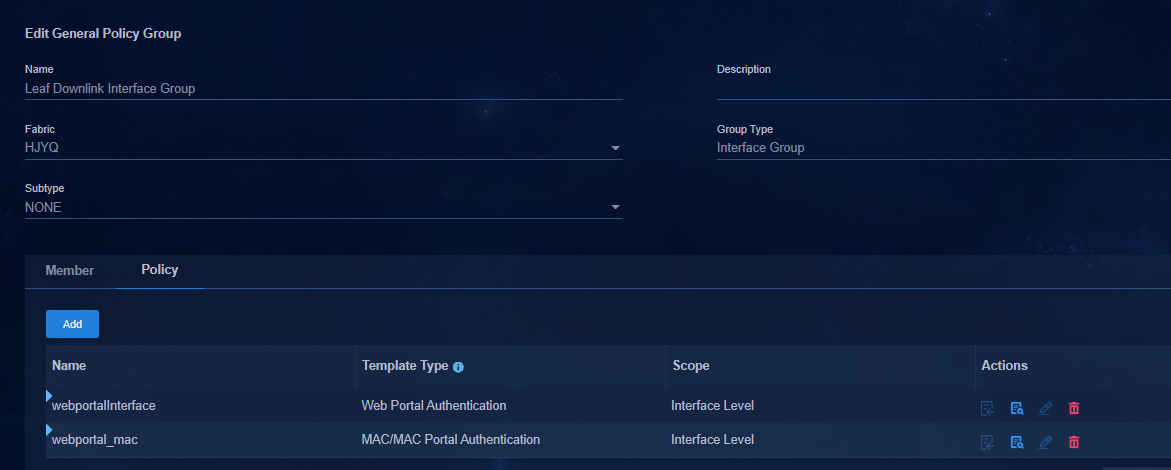
Create Layer 2 network domains and security groups
The configuration of creating Layer 2 network domains and security groups is the same as that in "Configure static AC authentication". For more information, see "Create a Layer 2 network domain" and "Create a security group."
Deploy configuration to the leaf device
Configure the third-party authentication server
· Configure the AAA server as follows:
#
radius scheme rd
primary authentication 10.99.12.189 vpn-instance vpn-default // IP address of the third-party authentication server.
primary accounting 10.99.12.189 vpn-instance vpn-default
accounting-on enable send 255 interval 15
key authentication cipher $c$3$01oCMscY9DPxDQb6Hca466591nHq92rWSQ==
key accounting cipher $c$3$RCI/F6pW6YdEZ8kiKZ44niy+ubmo8FrrIg==
timer realtime-accounting 15
user-name-format without-domain
vpn-instance vpn-default
attribute translate
stop-accounting-packet send-force
attribute convert H3c-User-Group to H3C-Microsegment-Id received
microsegment 3502 associate vsi vsi4
microsegment 3504 associate vsi vsi3
microsegment 3505 associate vsi vsi3
microsegment 4090 associate vsi vsi5
#
· Configure the Web Portal as follows:
[Leaf-s75]dis web-auth server
Web server: Hotspot
Type : Remote
IP address : 10.99.12.189
IPv6 address : Not configured
URL : http://10.99.12.189/a79.html
Track ID : 1
Server state : Inactive
URL parameters : wlanacip=130.1.0.5
wlanacname=leaf-130.1.0.5
[Leaf-s75]
· Deploy leaf downlink interface configuration:
On the leaf device connected to the access device configured in the static access interface group, deploy the service-instance configuration to the downlink interface.
#
interface Bridge-Aggregation1024
port link-type trunk
port trunk permit vlan 1 101 to 3000 4093 to 4094
link-aggregation mode dynamic
stp tc-restriction
mac-based ac
mac-authentication // MAC authentication
mac-authentication domain rd
mac-authentication parallel-with-dot1x
port-security free-vlan 1 4094
web-auth domain rd //web-auth authentication
web-auth enable apply server hotspot
#
service-instance 2801
encapsulation s-vid 2801
xconnect vsi vsi18
#
service-instance 4094
encapsulation s-vid 4094
xconnect vsi vxlan4094
#
Configure H3C EIA authentication server
#
radius scheme hz1
primary authentication 110.0.0.100 vpn-instance vpn-default
primary accounting 110.0.0.100 vpn-instance vpn-default
accounting-on enable send 255 interval 15
key authentication cipher $c$3$zHvt8Q9eIMKWJ/BOJgUXSJPg65IBSQ==
key accounting cipher $c$3$Tp0bJhOUACFbng9D/kjF/hIKqM3Gsw==
timer realtime-accounting 15
user-name-format without-domain
vpn-instance vpn-default
attribute translate
stop-accounting-packet send-force
attribute convert H3c-User-Group to H3C-Microsegment-Id received
microsegment 3502 associate vsi vsi4
microsegment 3504 associate vsi vsi3
microsegment 3505 associate vsi vsi3
microsegment 4090 associate vsi vsi5
#
· Configure the Web Portal as follows:
[6550xe-up]disp web-auth server
Web server: eia
Type : Remote
IP address : 110.0.0.100
IPv6 address : Not configured
URL : http://110.0.0.100:9092/portal/
Track ID : 1
Server state : Active
URL parameters : Not configured
[6550xe-up]
· Deploy leaf downlink interface configuration:
On the Leaf device connected to the access device configured in the static access interface group, deploy the service-instance configuration to the downlink interface.
#
interface Bridge-Aggregation1024
port link-type trunk
port trunk permit vlan 1 101 to 3000 4093 to 4094
link-aggregation mode dynamic
stp tc-restriction
mac-based ac
mac-authentication // MAC authentication
mac-authentication domain hz1
mac-authentication parallel-with-dot1x
port-security free-vlan 1 4094
web-auth domain hz1 //web-auth authentication
web-auth enable apply server eia
#
service-instance 2801
encapsulation s-vid 2801
xconnect vsi vsi3506
#
service-instance 4094
encapsulation s-vid 4094
xconnect vsi vxlan4094
#
Configure the third-party authentication server
Take H3C EIA authentication server as an example, you need to configure the Portal server and RADIUS server.
· Configure Portal server: Configure the parameters according to the configured parameters of wlanacname and wranacip of the leaf devices.
· Configure RADIUS server: Configure the IP address of the RADIUS server according to the configuration of RADIUS scheme on the leaf device.
¡ In a non-DRNI environment, the RADIUS NAS IP is the VSI 4094 IP address of the leaf device.
¡ In a DRNI environment, the NAS IP addresses of local and peer are configured in the RADIUS scheme. Both IP addresses need to be configured.
Configure Portal server
Configure a server
Navigate to the Automatic > User Service > Access Service page. Click the Portal Service link in the upper right corner to go to the Portal Service Management page. You can configure the server, device, and IP address group on this page.
A separate EIA can be used for Web-portal scenarios. This section uses the EIA to describe the Web-portal server.
For the parameters of Basic Information, and parameters for the Portal Server and Portal Web column, use the default settings. Set Permitted for Bind IP Group to Port Groups in the Basic Information column. For details about each parameter, see the Help link in the upper right corner of the page.
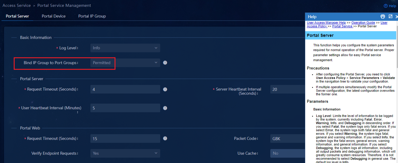
|
|
NOTE: · After completing the Portal Server configuration, you need to click Validate for the configuration to take effect under the Automation > User > Access Parameters > Validate. · If multiple operators make concurrent modifications to the Portal Server configuration, the last modified modification overwrites the previous modification. |
Click Add in the Advanced Information column. Open the Service Type List and add the service type as needed, as shown in the following figure.
· Service Type ID: The device determines the corresponding authentication scheme according to the service type selected by the user. The administrator configure the corresponding settings according to the actual networking and the configuration of the iMC service and the device.
· Service Type: Service Type ID is the information used by the device. Users can understand it clearly. Service Type ID is displayed on the Portal authentication home page to help users understand service types. The service type information is required and cannot be the same as the existing service type information. The number of service types cannot exceed 64.
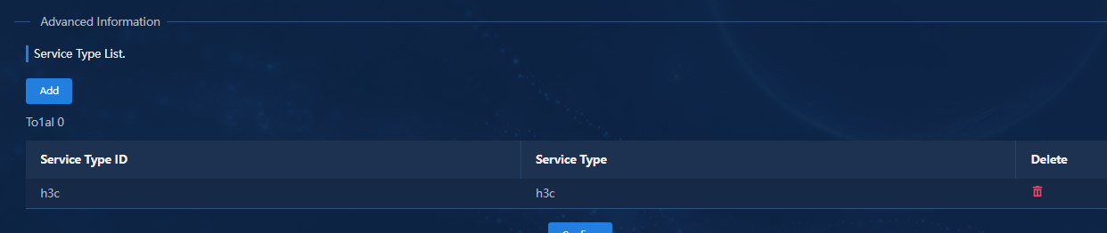
Navigate to the Automatic > User Service > Access Service page. Click the Portal Service link in the upper right corner to go to the Portal Service Management page. Click the IP Address Group Configuration tab and add or modify an IP address group.
· IP Group Name: Specify the name of the IP address group.
· IPv6: Distinguish whether the IP address group is an IPv6 address.
· Start IP: Specify the start IP address of the IP address group.
· End IP: Specify the end IP address of the IP address group.
· Action: Select Normal.
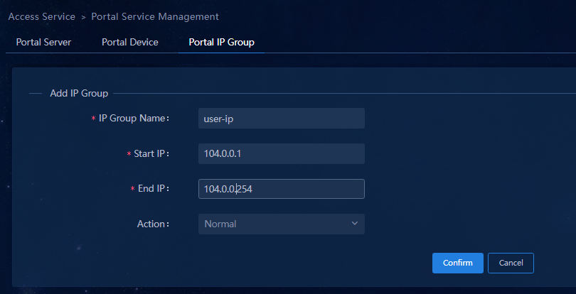
Configure a device
Navigate to the Automatic > User Service > Access Service page. Click the Portal Service link in the upper right corner to go to the Portal Service Management page. Click the Device Configuration tab.
1. Click Add to open the device configuration page.
Add device configurations for different Leaf devices. The interface group shares the IP address group created earlier.
¡ Device Name: The name of the Portal access device cannot be the same as the name of any existing device.
¡ Public IP address: The IP address of the Portal access device and the VSI-interface 4094 address.
¡ Key: Both ends of the Portal server need to configure the same shared key when communicating with the device, otherwise it cannot pass the receiver's validation and the key set when the AAA policy template is configured.
¡ Advanced Information: Use the default settings.
2. After completing the configuration, click OK
to save the configuration. Click ![]() in the Action
column of the list to go to the portal group information management page.
in the Action
column of the list to go to the portal group information management page.
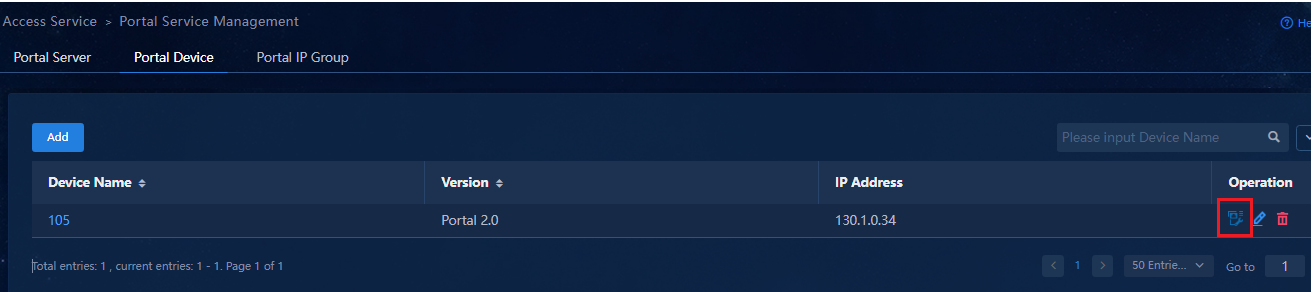
3. Click Add to add a port group. Select the created IP address group from the drop-down list as follows.
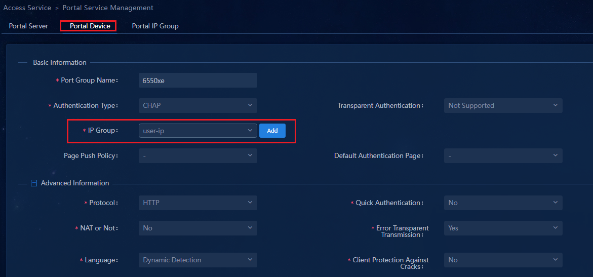
Configure RADIUS server
The access device configuration is used for RADIUS authentication. By default, the controller synchronizes the information about leaf device to the EIA. Manual configuration is not required.
If EIA is configured as a third-party authentication device, you need to manually configure information about the Access device.
· Non-DRNI networking: Set the IP address of the Leaf device VSI 4094 as the IP address of the Access device.
· DRNI networking: Set the IP address of the Leaf device nas-ip of RADIUS and the IP address of Local and Peer.
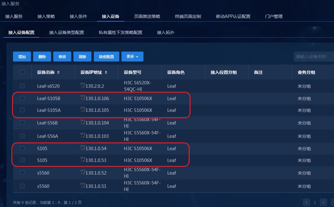
Configure user authentication
The EIA authentication server can be connected to a browser running HTTP/HTTPS or a host running the Portal client (iNode client). Web-portal scenario EIA addresses can use a separate EIA. This section uses the EIA to describe the Web-portal server.
|
|
NOTE: Port groups of different devices share IP address groups. The browsers running HTTP/HTTPS protocols are currently supported by the current device version. The iNode client mode is not supported by the current device version. |
If the endpoint opens the Internet Explorer page and enters any IP address, the endpoint is redirected to the URL page configured on the Web Portal.
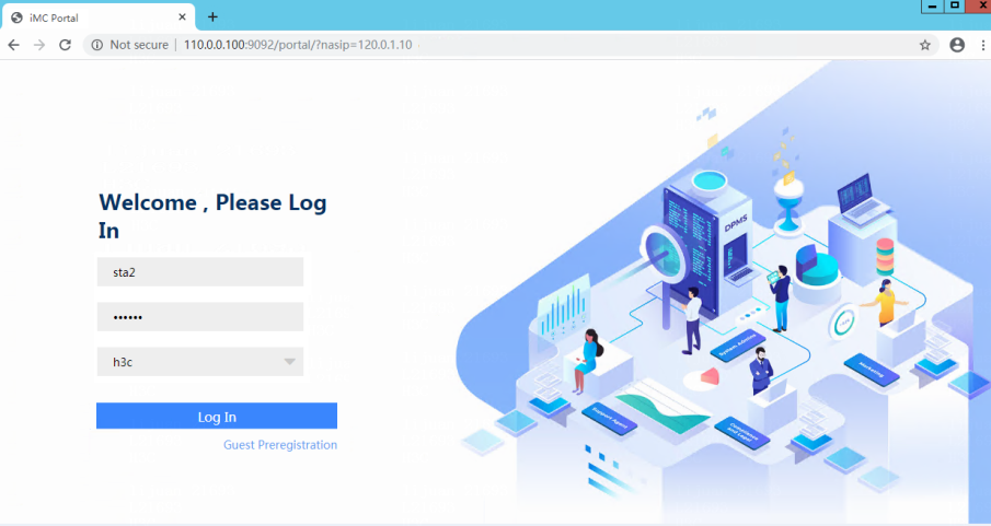
Enter the username and password to log in.
Use the iNode client, click the refresh icon in the upper right corner of the page. Obtain Portal server information. Enter the username and password to complete the authentication.
Guest access or access upon authentication failure
|
|
IMPORTANT: · Only 802.1X supports guest access and access upon authentication failure. · Unicast trigger must be enabled when enabling guest access. · Guest and Mac Portal are mutually exclusive. |
Guest access
Guest online is mainly used to allow users to access resources in a specific security group after accessing the network without a configured authentication server. The specific security group is a Guest-type security group.
Create a guest Layer 2 network domain
Navigate to the Automation > Campus Network > Private Network > Layer 2 Network Domain page.
1. Click Add to open the Layer 2 Network Domain page. The parameters are configured as follows:
¡ Private Network: As a best practice, select User Private Network.
¡ Type: Select Guest.
¡ IPv4 Address Allocation: Select Auto.
¡ DHCP Server: Select the DHCPv4 server.
¡ IPv4 Address Lease Duration: It is 30 minutes by default.
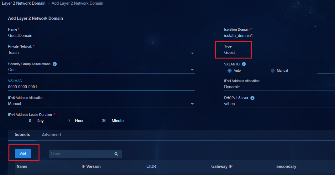
2. Click the Subnets tab, and click Add to add subnet network segment.

3. After completing the configuration, click OK to return to the Layer 2 Network Domain page. Click OK to complete the configuration.
Create a guest security group
Navigate to the Automation > Campus Network > Security Group > User Security Group page. Click Add to open the page for adding a security group.
Only one guest security group can be configured in an isolation domain. If there are multiple fabrics in an isolation domain, all fabrics share one Guest security group. Select Guest for Type. Select the Layer 2 Network Domain Information tab and click Add to open the page for adding Layer 2 network domain. Select the Layer 2 network domain of the previously configured guest type.
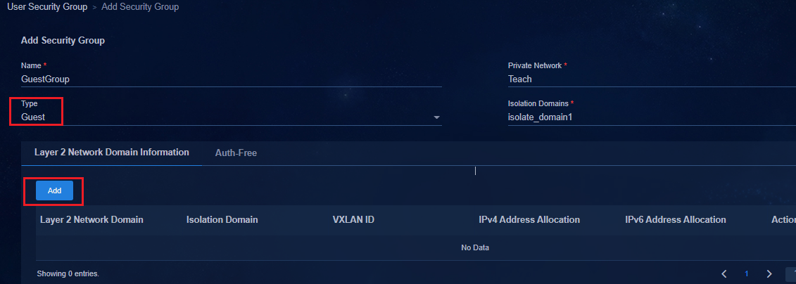
Enable guest access for the a policy template
Enable the guest function in "Interface policy template - 802.1X authentication."
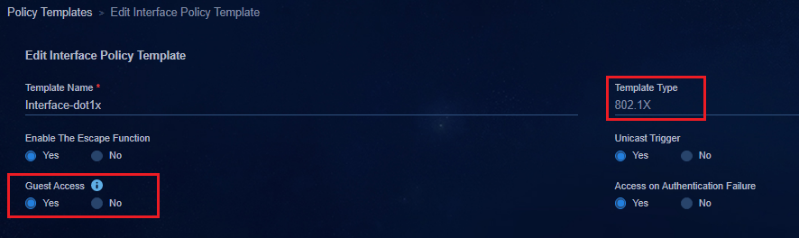
When the policy template is applied to the Leaf downlink interface group, the following configurations are delivered:
#
interface Ten-GigabitEthernet1/0/0/14
port link-mode bridge
port link-type trunk
port trunk permit vlan 1 101 to 3000 4093 to 4094
stp tc-restriction
mac-based ac
dot1x
undo dot1x multicast-trigger
dot1x unicast-trigger
dot1x guest-vsi vsi10 // VSI corresponding to Guest
dot1x critical eapol
dot1x critical profile SDN_GLOBAL_CRITICAL_PROFILE
port-security free-vlan 1 4094
#
service-instance 4094
encapsulation s-vid 4094
xconnect vsi vxlan4094
#
User online and obtaining address
When the endpoint PC accesses the network, the user directly obtains the guest authorization and address and accesses the specific network resources of the guest security group.

Access upon authentication failure
When an authentication failure occurs, users can access the network and resources in a specific security group after an 802.1X authentication failure. The specific security group is a security group of the authentication failure type.
Create a Layer 2 network domain for access upon authentication failure
Navigate to the Automation > Campus Network > Private Network > Layer 2 Network Domain page.
1. Click Add to open the Layer 2 Network Domain page. The parameters are configured as follows:
¡ Private Network: As a best practice, select User Private Network.
¡ Type: Select Authentication Failure.
¡ IPv4 Address Allocation: Select Auto.
¡ DHCP Server: Select the DHCPv4 server.
¡ IPv4 Address Lease Duration: The default setting is one day.
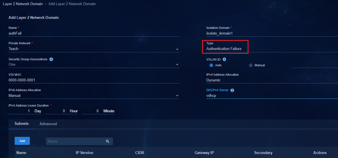
2. Click the Subnets tab, and click Add to add subnet network segment.
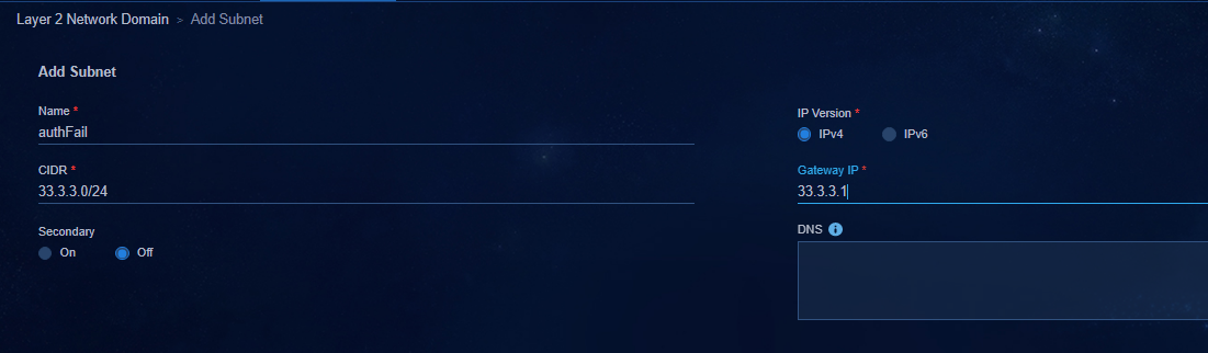
3. After completing the configuration, click OK to return to the Layer 2 Network Domain page. Click OK to complete the configuration.
Create a security group for access upon authentication failure
Navigate to the Automation > Campus Network > Security Group > User Security Group page. Click Add to open the page for adding a security group.
Only one authentication failure security group can be configured in an isolation domain. If multiple fabrics exist in an isolation domain, all fabrics share the same authentication failure security group. Select Authentication Failure for Type, and click Add. Select the Layer 2 network domain whose authentication failure type is configured previously.
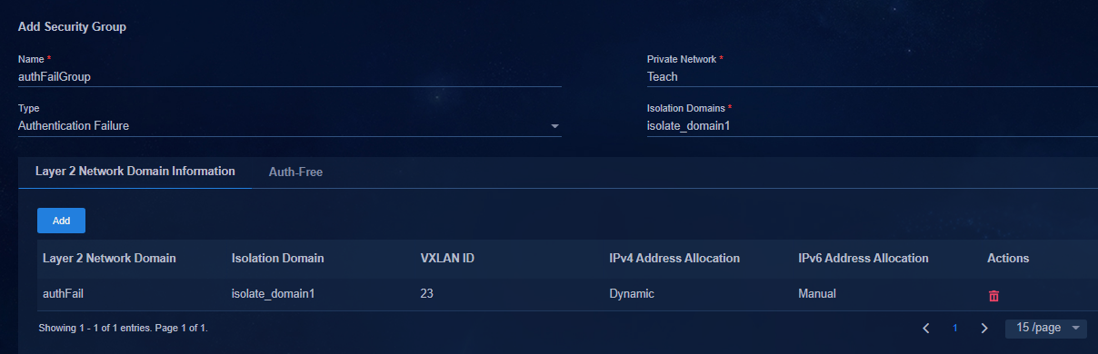
Enable access upon authentication failure for a policy template
Enable access upon authentication failure in "Interface policy template - 802.1X authentication."
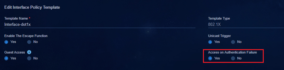
After the policy template is applied to the leaf downlink interface group, the following configurations are issued:
#
interface Ten-GigabitEthernet1/0/0/14
port link-mode bridge
port link-type trunk
port trunk permit vlan 1 101 to 3000 4093 to 4094
stp tc-restriction
mac-based ac
dot1x
undo dot1x multicast-trigger
dot1x unicast-trigger
dot1x guest-vsi vsi10
dot1x auth-fail vsi vsi11 //VSI of authentication failure
dot1x critical eapol
dot1x critical profile SDN_GLOBAL_CRITICAL_PROFILE
port-security free-vlan 1 4094
#
service-instance 4094
encapsulation s-vid 4094
xconnect vsi vxlan4094
#
User online and obtaining address
Initiate 802.1X authentication on the endpoint or PC. After the authentication fails, the user can access network resources specified in the security group specific to users that fail the authentication.
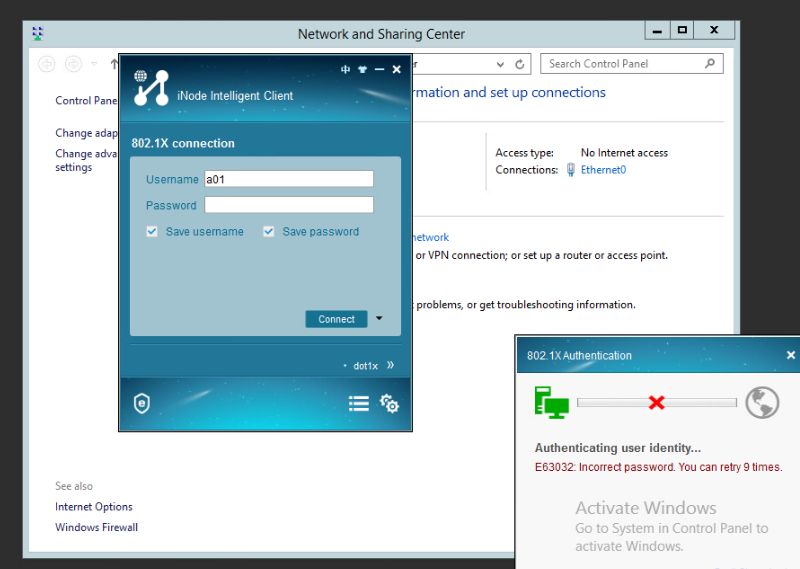
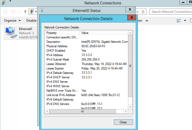
Configure the broadband IoT service
The broadband IoT service in the AD-Campus solution is authenticated through MAC addresses. A user triggers authentication through traffic. The EIA identifies the user and matches the rules configured for broadband IoT service. The system automatically creates an account and password based on the MAC address of the user, so that the user can directly come online through authentication without providing the username and password.
The configuration can be based on MAC address range, IP address range, or endpoint identification.
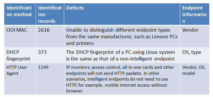
Navigate to the Automation > User > Access User > Mute Terminal User Config Profile page.
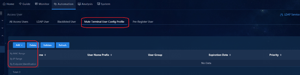
· By MAC Range: Set a MAC address range. If a user's MAC address matches the configured MAC address range, the system automatically creates an account for the user and authenticates the user with the account. Then, the system adds the authenticated user to a user security group and assigns the user the IP address of the user security group.
· By IP Range: Set an IP address range. Configure the mac-authentication carry user-ip exclude-ip acl *** command in the downlink interface of the Leaf device.
· By Endpoint Identification: Set the endpoint device parameter information. The endpoint fingerprint information is carried when the client authenticates to come online. If the endpoint fingerprint information matches the configured endpoint device parameter information, the system automatically creates an account for the user and authenticates the user with the account. Then, the system adds the authenticated user to a user security group and assigns the user the IP address of the user security group.
|
|
IMPORTANT: · The priorities of configured MAC address range and IP address range must be different. If a client matches both the MAC address range and IP address range, the one with higher priority applies. The smaller the priority value, the higher the priority. · Restrictions of the mac-authentication carry user-ip command: Configure this command only for By IP Range authentication and when Bind User IP Address authentication is configured in the access policy. In any other cases, do not configure this command. If the endpoint device needs to be configured with a static IP address for authentication, the controller delivers the static IP address to EIA by issuing the ARP snooping command. |
Fast online based on MAC address ranges
By OUI MAC range, two modes are available: manually adding and batch importing.
Click Add, and select By MAC Range from the drop-down list. Set the priority in the range of 0 to 999. The default value is 0. The smaller the value is, the higher the priority is.
In the MAC Address Range area, you can manually add MAC address ranges or import MAC addresses.
Manually add a MAC address range
Click Add to open the Add MAC Address Range page. Enter the MAC address range, and click Confirm. You can add multiple MAC address ranges. Each address range can be configured according to the requirements.
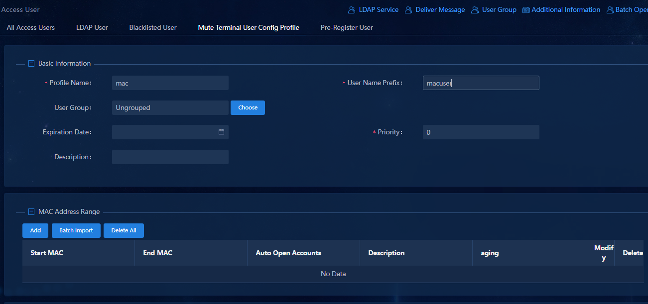
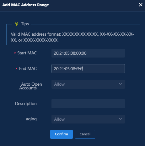
Configure the parameters on the page as follows:
· Auto Open Accounts: Set Allow or Disable.
¡ Allow: If an endpoint matches the MAC address range, the system automatically creates an account to authenticate the user, adds the authenticated user to the corresponding security group and obtains an IP address for the user.
¡ Disable: No account is created automatically. The authenticated user triggers the MAC Portal authentication to enter the BYOD security group. The administrator opens an account for the user by navigating to the Monitor > Monitor List > Endpoint > Access Endpoint page and clicking the open account icon in the Operation column.
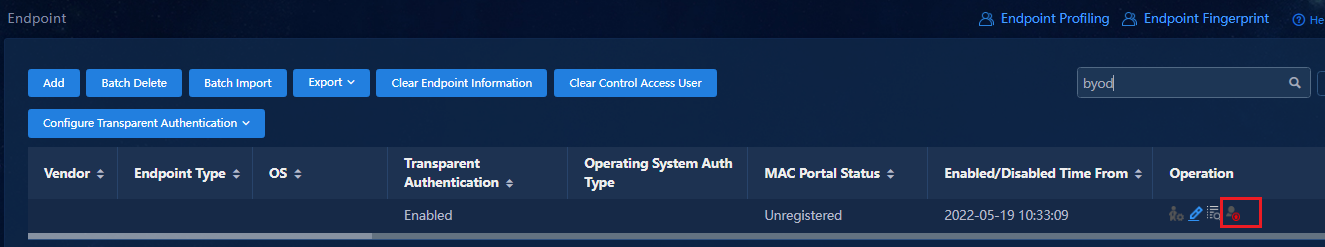
· Aging: Set Allow or Prohibit.
¡ Allow: EIA allows the authenticated mute endpoints to go offline after timeout in the case of no traffic, NAS reboot, and NAS-Port-down.
¡ Prohibit: In the case of no traffic, NAS reboot, and NAS-Port-down, EIA does not allow the mute endpoint to age and the mute endpoint on the EIA stays online. When the Leaf device recovers, Leaf requests the online information from EIA to restore the online status of the mute endpoint in case the dumb terminal does not send traffic and fails to be restored to the online status.
Import access users in bulk
1. Click Batch Import to open the Batch Import Mute Terminal MACs page. Batch import supports the downloading of the import template. Click the Mute Terminal Mac Address Range Import Template link to download the import template. Enter the MAC address ranges to be imported according to the downloaded template.
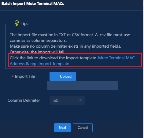
2. Click Upload to import the file, select the column delimiter, click Next to bulk import dumb terminal MAC address ranges and click Confirm to complete the configuration.
3. Select an access service in the Access Service column, and click Confirm to save the configuration.
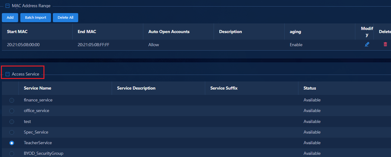
4. To have the added MAC address ranges take effect immediately, you need to select the MAC address ranges and click Validate. If you do not click Validate, the MAC address ranges do not take effect until the system polling time expires (in 10 minutes).
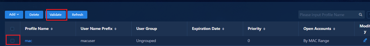
After the MAC address ranges are successfully configured, traffic from endpoint devices can trigger authentication. The system matches them with the MAC address ranges, automatically creates user accounts, and adds the authenticated users to the corresponding security groups to obtain IP addresses.
|
|
IMPORTANT: A manual Validate operation can have about 2000 MAC addresses take effect. If the number of MAC addresses is large, select the MAC address ranges and click Validate in multiple batches. |
Fast online based on IP address ranges
Click Add, and select By IP Range from the drop-down list. Set the priority in the range of 0 to 999. The default value is 0. The smaller the value is, the higher the priority is. The priorities of MAC address range and IP address range are compared. They should not be set to the same priority.
In the IP Address Range area, you can manually add MAC address ranges or import MAC addresses.
Manually add a MAC address range
Click Add to open the Add IP Address Range page in the IP Address Range column. Click Confirm to complete the settings.
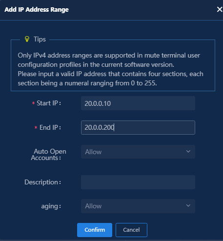
|
|
IMPORTANT: · The IP range entered needs to be the same as the subnet of the security group set in the Access Service. The subnet network segment of the security group can be viewed by navigating to Automation > Campus Network > Private Network > Layer 2 Network Domain in the SeerEngine-Campus and clicking the subnet link in the list. · Multiple IP address ranges can be added. Each IP address range's parameters can be set according to the requirements. |
Import access users in bulk
1. Click Batch Import. Downloading the template is supported. Click the Mute Terminal IP Address Range Import Template link to download the template. Enter the IP address ranges to be imported according to the downloaded template.
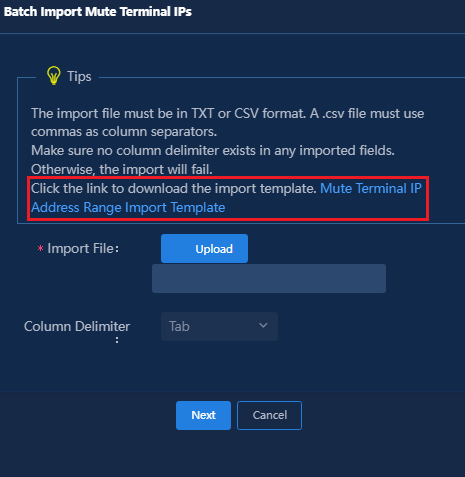
2. Click Upload to import the file, select the column delimiter, click Next to bulk import dumb terminal MAC address ranges and click Confirm to complete the configuration.
3. Select an access service in the Access Service column, and click Confirm to save the configuration.
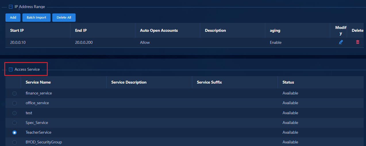
4. To have the added IP address ranges take effect immediately, you need to select the IP address ranges and click Validate. If you do not click Validate, the MAC address ranges do not take effect until the system polling time expires (in 10 minutes).
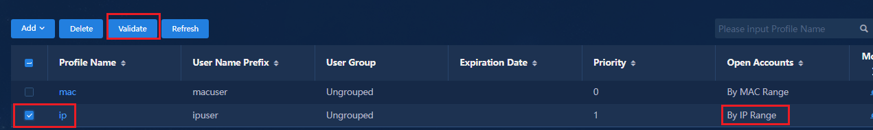
After the IP address ranges are successfully configured, traffic from endpoint devices can trigger authentication. The system matches them with the IP address ranges, automatically creates user accounts, and adds the authenticated users to the corresponding security groups.
5. Issue the mac-authentication carry user-ip exclude-ip acl *** command to the downlink interface of the Leaf device. After the command is issued, the client sets the static IP address. When the client triggers an authentication, if its IP address matches a configured IP address range, the system automatically creates a user account to authenticate the user, and adds the authenticated user to the configured access group. The description of the mac-authentication carry user-ip exclude-ip acl *** command is as follows:
¡ mac-authentication carry user-ip: Obtains the static IP address of the endpoint device and sends it to the EIA server to trigger quick online authentication.
¡ exclude-ipacl: User packets from the specified network segment of the ACL do not trigger MAC authentication.
The following commands are issued to the Leaf device:
#Create acl to match the address of fe80.
acl ipv6 basic 2000
rule deny source fe80:0::0:0 16
#
#Deliver the mac-authentication carry user-ip command on Leaf downlink interface.
interface gigabitethernet 1/0/1
mac-authentication carry user-ip exclude-ip acl 2000
#
|
|
IMPORTANT: · In the current AD-Campus solution, the mac-authentication carry user-ip exclude-ip acl *** command is required to filter IPv6 link local addresses starting with fe80. · When an endpoint user uses a static IP address to access, the IP address carried in the user packets might not be the actual IP address of the user. For example, in IPv4 static address networking, the IP address carried in the user packets is the IPv6 link local address starting with fe80. After the mac-authentication carry user-ip command is configured, the device initiates a MAC address authentication request to the server with an IP address that is not the user's actual IP address. This causes the server to bind the wrong IP address for the user or the failure of the IP address and the MAC address matching. To avoid these issues, you can specify the exclude-ip acl parameter to prohibit the MAC address authentication for users in the network segment specified in the ACL. |
Fast online based on endpoint identification
Click Add and select By Endpoint Identification in the drop-down list.
You can manually add or import endpoint identification entries. The following only describes the content that requires special attention. For information about other settings, see "0Fast online based on MAC address ranges."
· To manually add an endpoint identification entry, click Add to open the Add Terminal Identity page, and configure the endpoint identification items (OS, endpoint type, and vendor).
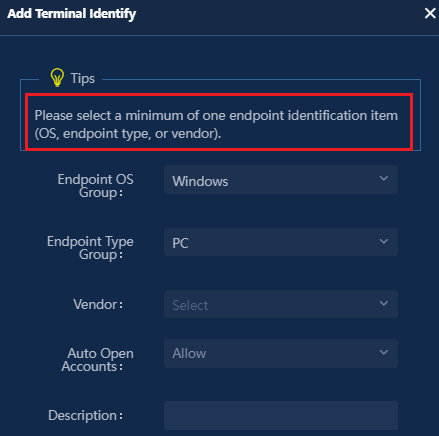
· To import identification items in batches, you can use the import template in the link.
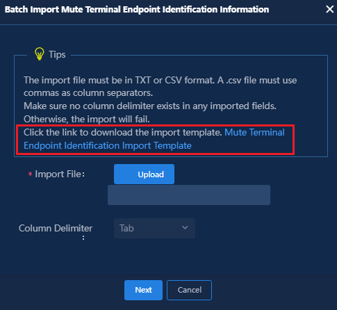
· After completing the configuration, you need to select the added items and click Validate. If you do not click Validate, the MAC address ranges do not take effect until the system polling time expires (in 10 minutes).
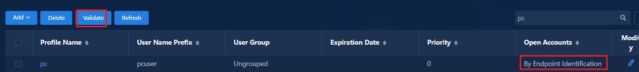
Traffic from endpoint devices triggers authentication. The system matches the fingerprints of the endpoints with the endpoint identification entries. If matches are found, the system automatically creates user accounts and adds the authenticated users to the corresponding security groups.
Keep broadband IoT endpoints online for a long time
To keep IoT endpoints online for a long time, associate the offline check period (hours) with ARP/ND snooping. Trigger keepalive 30 seconds before the ARP/ND entries age to keep broadband IoT endpoints online. To keep the broadband IoT endpoints online for 1 to 2 offline check periods, you only need to set the Offline Check Period in the access policy of EIA as follows:
Navigate to the Automation > User
> Access Service page, and click the Access Policy Management
link to open the Access Policy page. Click ![]() in
the Edit column for the access policy name of the list. Modify the Offline
Check Period (Hours) of the access policy in the Authorization
Information column. The recommended value is 24 hours.
in
the Edit column for the access policy name of the list. Modify the Offline
Check Period (Hours) of the access policy in the Authorization
Information column. The recommended value is 24 hours.
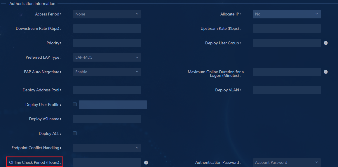
The following two methods can keep broadband IoT endpoints always online.
· Method 1: Set the offline check period to zero hours. Disable offline check to ensure that endpoints do not age without traffic for a long time and always keep online.
· Method 2: Based on the configuration of the offline check period, you need to set ARP snooping in the SeerEngine-Campus and configure the offline check period on the device to cooperate with ARP snooping. This method typically applies to keep specific broadband IoT endpoints always online.
a. Navigate to Automation > Campus
Network > Private Network > Layer 2 Network Domain,
and click ![]() in the corresponding column to open the Edit Layer 2 Network
Domain page.
in the corresponding column to open the Edit Layer 2 Network
Domain page.
b. On the Advanced tab of the Edit Layer 2 Network Domain page, set ARP Snooping to On and then click OK.
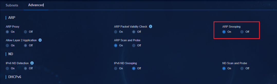
Deploy the ARP snooping enabling command to the leaf device:
#
vsi vsi4
description SDN_VSI_4
gateway vsi-interface 4
statistics enable
arp Snooping enable //Command deployed by the controller.
flooding disable all all-direction
vxlan 4
evpn encapsulation vxlan
mac-advertising disable
arp mac-learning disable
nd mac-learning disable
route-distinguisher auto
vpn-target auto export-extcommunity
vpn-target auto import-extcommunity
dhcp snooping binding record
#
In addition to the offline check period and ARP snooping settings, you need to manually configure the mac-authentication offline-detect mac-address xxxx-xxxx-xxxx timer xxxx check-arp-or-nd-snooping command to enable the cooperation between the offline check period and ARP/ND snooping, so as to trigger keepalive 30 seconds earlier than the aging of ARP/ND entries.
The command configuration is as follows:
The timer refers to the offline check period, which must be longer than the ARP aging time, for example, 3600 seconds.
#
mac-authentication offline-detect mac-address 0001-0002-0003 timer 3600 check-arp-or-nd-snooping
#
|
|
IMPORTANT: The mac-authentication offline-detect mac-address xxxx-xxxx-xxxx timer xxxx check-arp-or-nd-snooping command must be configured on each authentication endpoint. The mac-address keyword specifies the MAC address of the endpoint. If you do not configure this command and only configure the offline check period, the collaboration between ARP snooping and offline check period cannot be realized. When the offline check period expires, the endpoint will go offline if no traffic is present. |
Role-based permission control
Introduction
The campus controller supports role-based permission control. The controller assigns permissions to login operators according to the their roles. This section mainly introduces permission configuration related with isolation domains and fabrics.
Basic concepts
Groups
The system assigns operators to various groups for hierarchical management. You can configure a role for a group to control the permissions of operators in the group. The system predefines four default groups. You can also create groups as needed.
· System Manager Group: Group of operators with permissions to manage system settings.
· System Viewer Group: Group of operators with permissions to view system settings.
· Service Manager Group: Group of operators with permissions to manage network devices and alarms.
· Service Viewer Group: Group of operators with permissions to view network devices and alarms.
Navigate to the System > Authority management > Groups page.
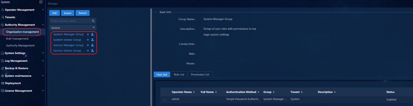
|
|
IMPORTANT: · You cannot delete a group that is being used by an operator. · You cannot change the name of a group. · You cannot add a group that exists already. · Up to 10 levels of sub-groups can be created. · Due to the performance limit, a maximum of seven levels of groups can be imported. |
Roles
A role defines a set of permissions for a type of users. The system adopts role-based permission control, which can refine the grouping of user permissions and facilitate the management of user permissions. The system provides a series of roles by default, and you can also define roles as needed. The campus network mainly involves the following default roles:
· Campus System Manager: Role with permissions to manage the campus network information.
· Campus System Viewer: Role with permissions to view the campus network information.
· Campus Area Manager: Role with permissions to manage specific campus network information.
· Campus Area Viewer: Role with permissions to view specific campus network information.
Navigate to the System > Authority management > Roles page.
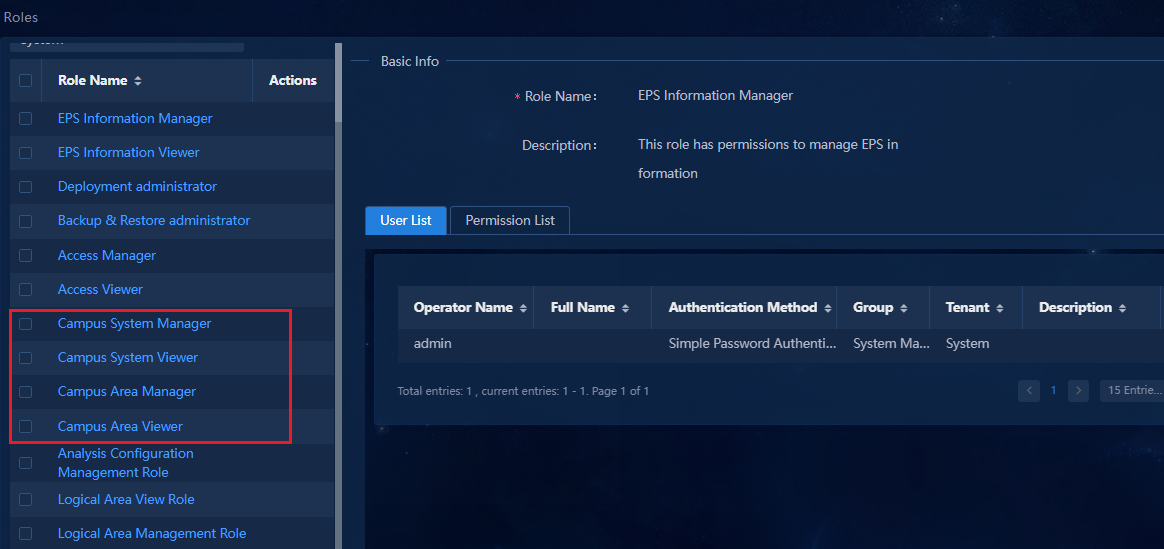
|
|
IMPORTANT: · The campus area roles do not contain isolation domain or fabric permissions by default, and you need to manually add area permissions as needed. · You cannot add a role that already exists. · After deleting a role, you can add another role with the same name as the deleted role. · Delete a role with caution. Deleting a role removes permissions from users with that role. |
Permissions
A permission defines the operations and data resources for a resource type. You can add, modify, delete, and view permissions. The system provides a series of permissions by default. You can also define permissions as needed. By default, a new user, group, or role has all the data resources under that permission by default.
The system also supports configuring the data resources for a permission. For example, an area manager can select its corresponding isolation domains and fabrics as the resources of the permission. Operations controlled by this permission can only process the resources specified in the permission.
Navigate to the System > Authority Management > Permissions page.
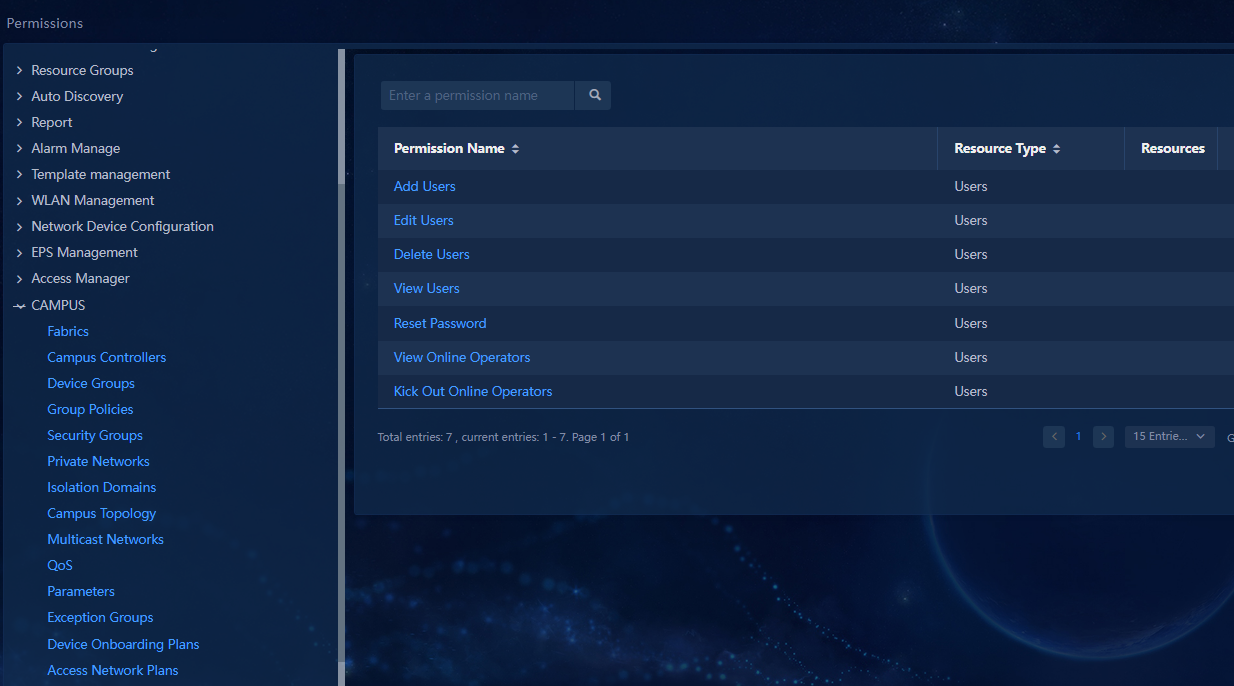
|
|
IMPORTANT: · The admin operator is the super administrator and has all permissions by default. · You cannot change the name of a permission when modifying it. · You cannot add a permission that already exists. · If you have the permissions to modify or delete data and no permissions to view data, the associated data is not displayed on the page. · If only part of the resource data is specified for a permission, the permission does not allow the user to view, modify, or delete the other data. · Delete the permission with caution. Deleting a permission removes corresponding operation permission or data permission from the users. |
Configure role-based access control
Add a permission
Add isolation domain sub-permissions for the area manager
1. Navigate to the System > Authority Management > Permissions page, and click Add. Enter the permission name, select CAMPUS as the permission group, and select Isolated Domains as the resource type (you can enter a name keyword to filter resource types).
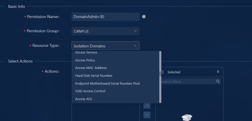
2. In the Select Actions column, you can
select Read&write isolation domains (for area managers) or Read
isolation domains (for area viewers). Then click ![]() to
add the selection to the Selected list.
to
add the selection to the Selected list.
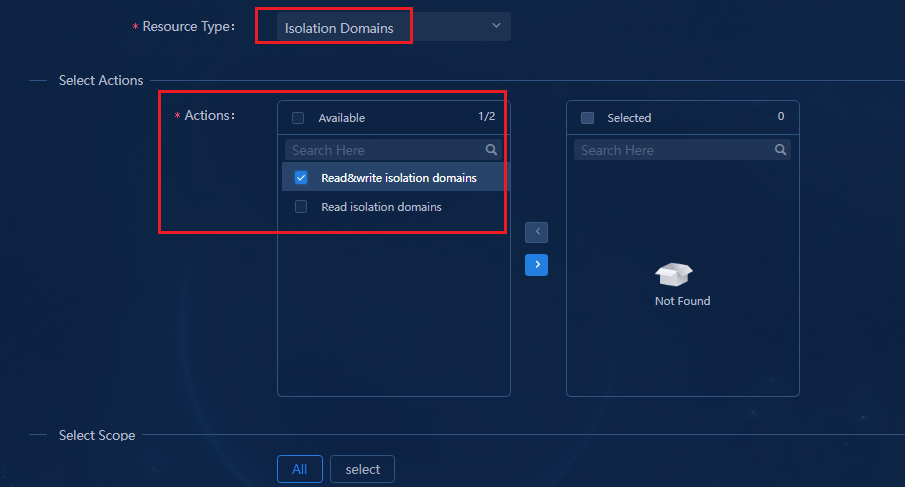
3. In the Select Scope column, select All or Select. This document uses Select as an example. Click Select Resources to specify corresponding isolation domains and then click Select to complete the selection.
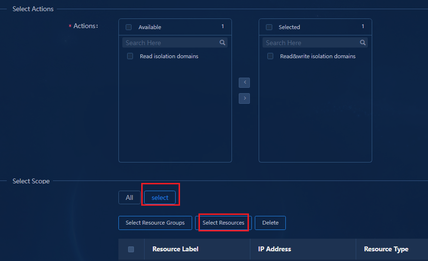
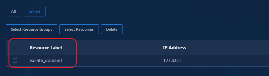
4. Click OK. A sub-permission for the area manager is added under the System > Permissions > Campus > Isolation Domains.
![]()
Add fabrics sub-permissions for the area manager
1. Navigate to the System > Authority Management > Permissions page, and then click Add. Enter the permission name, select CAMPUS as the permission group and Fabrics as the resource type.
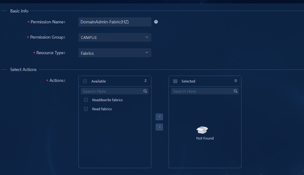
|
|
IMPORTANT: If both Campus and DC controller are deployed, two fabrics permissions are available. The one with scope configuration is the fabrics permission for Campus. |
2. In the Select Actions column, you can
select Read&write fabrics (for area managers) or Read fabrics
(for area viewers). Then click ![]() to add the
selection to the Selected list.
to add the
selection to the Selected list.
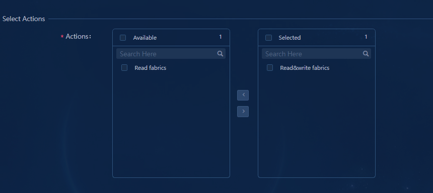
3. In the Select Scope column, select All or Select. This document uses Select as an example. Click Select Resources to specify corresponding fabrics and then click Select to complete the selection.
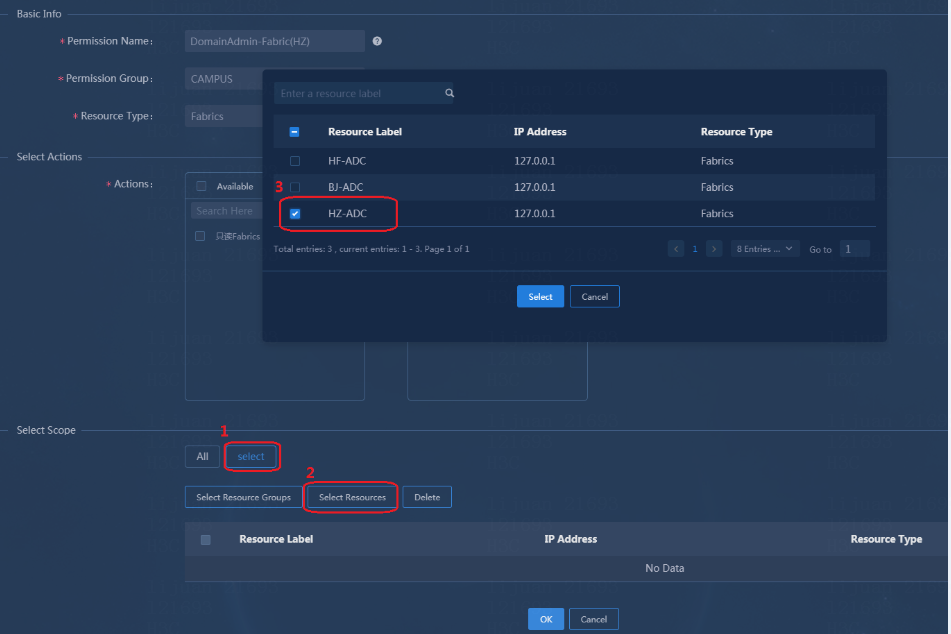
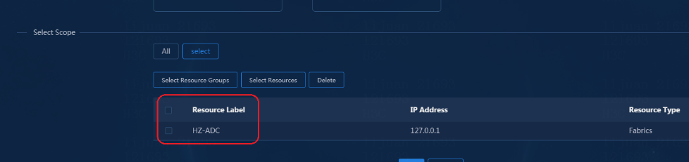
4. Click OK. A sub-permission for the area manager is added under the System > Permissions > Campus > Fabrics.
![]()
Add a customized role
1. Navigate to the System > Authority Management > Roles page. Click Add and enter the role name. Click Select to open the select permissions page (if there are multiple permission types, you can enter the permission name).
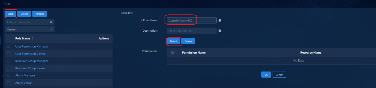
2. Enter the name of the permission added in "Add a permission", and click Search. Select the permission names and then click OK to return to the Select page.
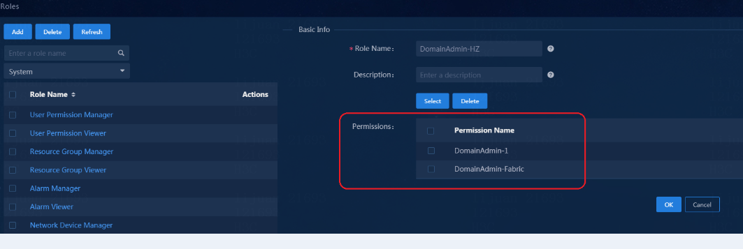
3. Click OK to complete the addition of the area role. The added role can be viewed under the System > Authority Management > Roles.
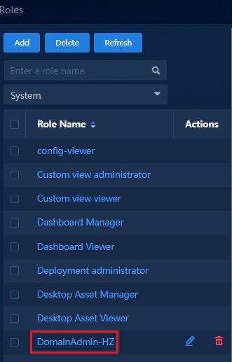
Add a customized group
1. Navigate to the System > Authority Management > Groups page. Click Add and enter the group name, email, and contact information.
2. Select the role added in "Add a customized role" and the default Campus Area Manager role (to ensure that the administrator has the necessary permissions for other basic modules of the campus network).
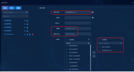
3. Click OK to complete the addition of the group. The added group can be viewed under the System > Authority Management > Groups.
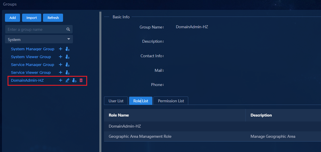
Add an operator
1. Navigate to the System > Operator Management > Operators page, and then click Add.
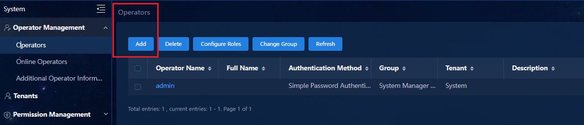
2. Enter the operator name, select System from the Tenant list, and select the customized group added in "Add a customized group" from the Group list. Select Simple Password Authentication as the authentication method, and enter the login password (pay attention to the complexity requirements).
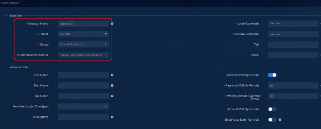
3. Click OK to complete the addition of the operator.
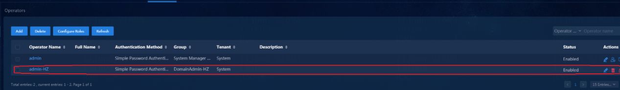
Verifying permission and domain management
Log in to the controller management page with the operator added in 0"Add an operator" and check whether the operator has the permissions as configured.
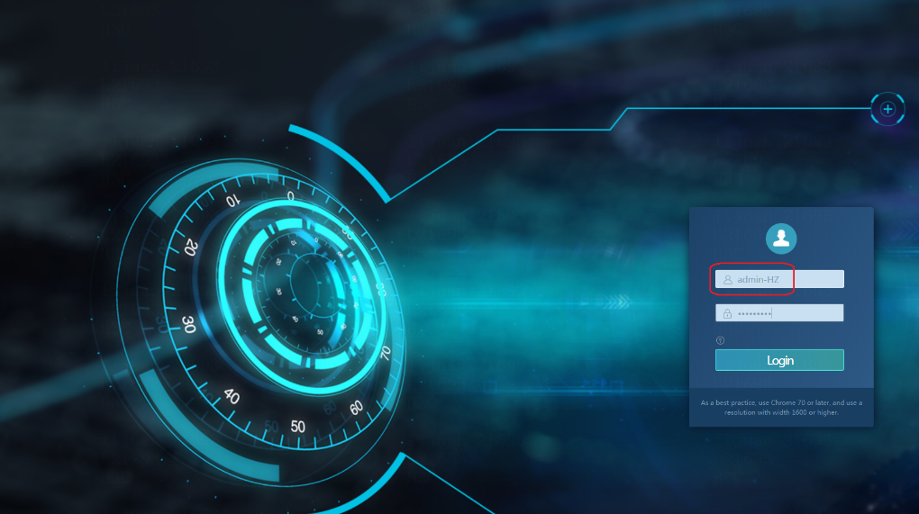
|
|
IMPORTANT: After a fabric is bound to an isolation domain, you need to add permissions to both the fabric and the corresponding isolation domain. Otherwise, the relevant pages are not displayed. |
Device onboarding plan
Navigate to the Guide > Campus Wizard > Device Onboarding Plan page.
The fabric available for the device onboarding plan configuration is only the authorized fabric. You can view the corresponding address pool configuration, role templates, etc. You cannot select and view the information about other fabrics.
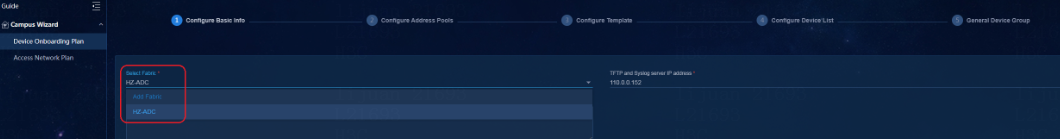
Campus topology
Navigate to the Monitor > Topology > Campus Topology page.
You can view the topology and device information of only the permitted fabric, and cannot view the topology information of other fabrics.
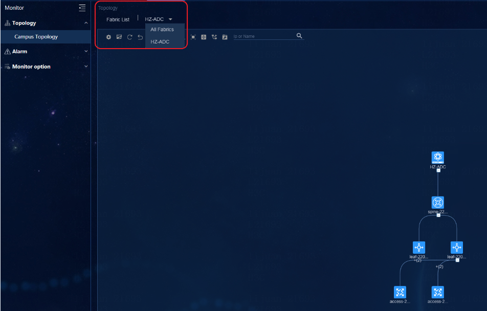
Fabrics
Navigate to the Automation > Campus Network > Fabrics page.
You can view and modify the information of only the authorized fabric, and cannot view the information of other fabrics.
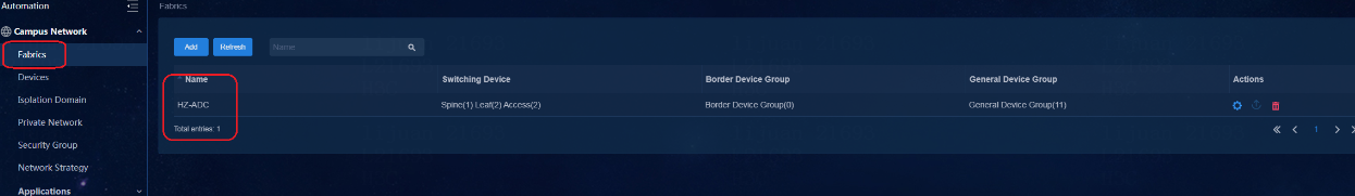
Physical devices
Navigate to the Automation > Campus Network > Devices > Physical Devices page.
You can view and modify the devices in only the authorized fabric. You cannot view the device information of other fabrics.
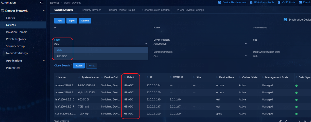
Isolation domain
Navigate to the Automation > Campus Network > Isolation Domain > Isolation Domain page.
You can view all isolation domains.
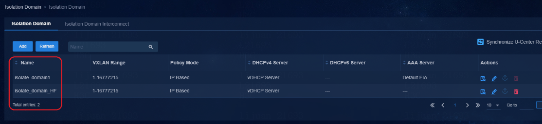
But you can view only the fabrics bound to the isolation domain to which the operator has a permission.
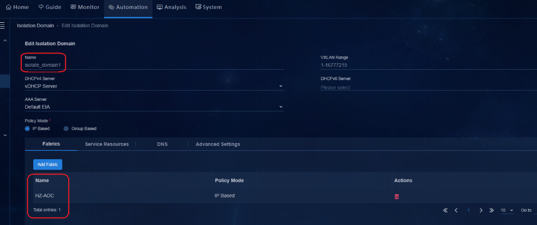
Fabrics bound to other isolation domains cannot be viewed.
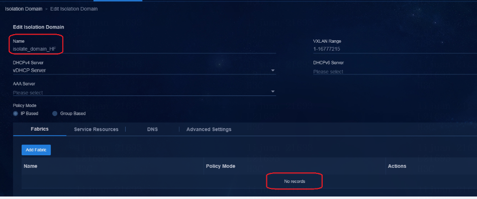
Public resources
Some of the public resources do not support area permission configurations for operators. All area managers only have the right to view and they do not have the right to edit the resources. All edit operations need to be operated by the system administrator. Mainly the following pages are involved:
· Navigate to the Automation > Campus Network > Device Groups > General Device Groups page, and click Policy Templates at the upper right corner of the page.
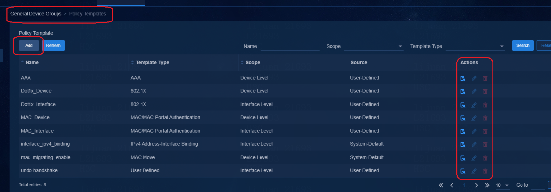
· Access the DHCP, AAA, Parameter, and other tabs under the Automation > Campus Network > Parameters.
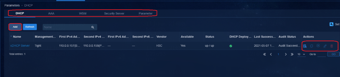
· Access Group Policies, Service Chains, Policy Template, and Time Ranges under the Automation > Campus Network > Network Strategy.

· Access the Device Replacement, IP Address Pools, VNID Pools, and other parameters under the Automation > Campus Network > Device Groups.
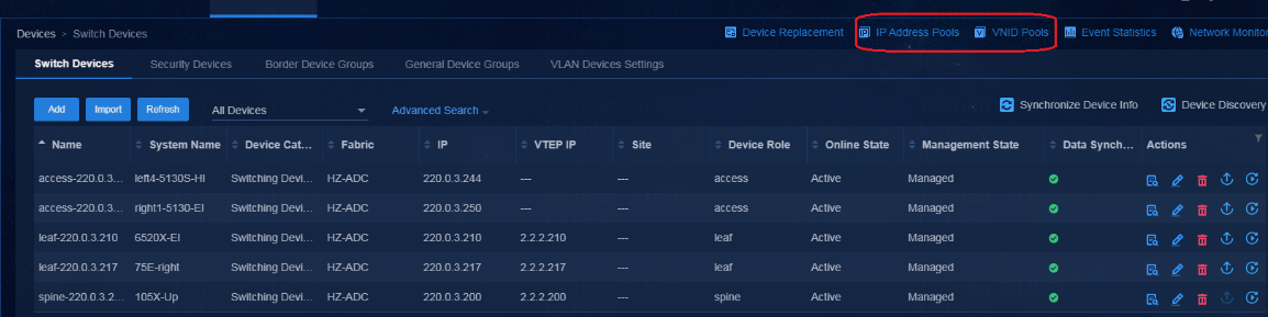
Configure the guest service
A guest is also a MAC Portal user. A guest is an external temporary user, and access rights are restricted. Temporary users do not have accounts; therefore, you need to configure Page Push Policy and BYOD Pages to implement the guest function and provide the guest registration function. A guest can submit the registration information to register automatically and log in to the system.
The system supports the following push methods for guests:
· PC: Default WEB Login (PC), QR Code Registration and Authentication (PC), SMS Message Registration and Authentication (PC).
· PHONE: Default WEB Login (Phone), QR Code Registration and Authentication (Phone), SMS Message Registration and Authentication (Phone).
· If the user pre-registration is completed on the SMS authentication page, it is necessary to complete the SMS modem or SMS gateway configuration. On the authentication page opened, a guest enters the cell phone number, and then obtains the password through the SMS modem to open an account and log in.
· If QR code method is used, a guest user can view a QR code on the Web page. The administrator scans the QR code and opens the URL to approve the user. The user can log in directly after the account is opened successfully.
· If QR code scanning method is used, it means that the administrator sets a QR code for visitors to log in. Users need to scan the QR code to access the network resources of guests.
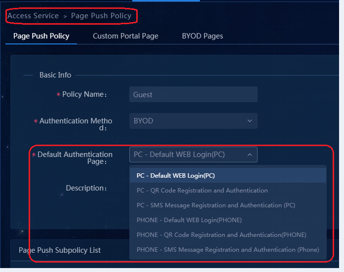
The following section introduces the PC - Default Web Login(PC) method, and the guest is configured with Guest Auto-Registration. That is, without manual approval by the administrator, the guest can come online automatically after pre-registration.
Configure guest management
Configure guest manager
Navigate to the Automation > User > Guest User page, and click the Guest Manager tab to open the Guest Manager page.
1. Click Add to open the page for adding a guest manager. Click Select Access User to open the Select Access User page. You can view all the access user information. Click Select Access User to select an access user as the guest manager. One guest needs to have one guest manager. You can also set the default guest manager.
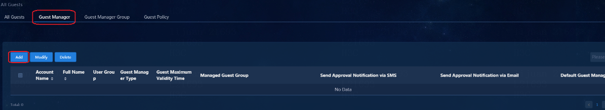
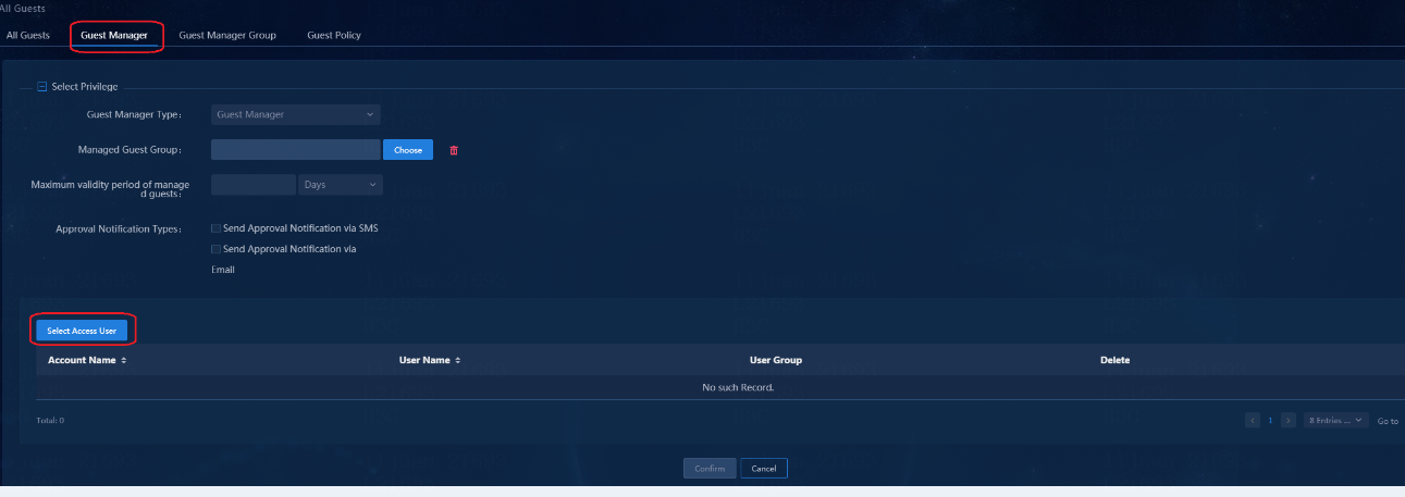
2. Select an access user and click OK to return to the page for adding a guest manager. Click Confirm to return to the Guest Manager page. The added access users are displayed on the Access User List. The Default Guest Manager column is No by default. Switching No to Yes can set the access user as the default guest manager as follows:
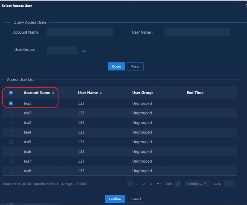
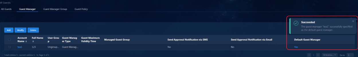
Configure a guest service
Before adding a guest service, you need to create the Layer 2 network domain, security group, access policy and access service corresponding to the guest service. For information about configuration, see "Create a Layer 2 network domain", "Configure a security group", "Configure access policies", and "Configure access services." For example, configure a Guest Security Group and set the corresponding access policy, and then configure the Guest Access Service to be associated with the Guest Security Group.
To configure a guest service:
1. Navigate to the Automation > User > Guest User > Guest Policy > Service page, and then click Add.
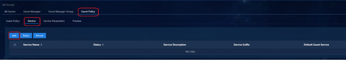
2. Select one or multiple configured access services on the Service page. Click Confirm to open the page for the result of adding Access service. Click Cancel to return to the Service page. Click Yes or No in the Default Guest Service column to switch the default guest service. Note that a default guest service is needed in the guest service list.
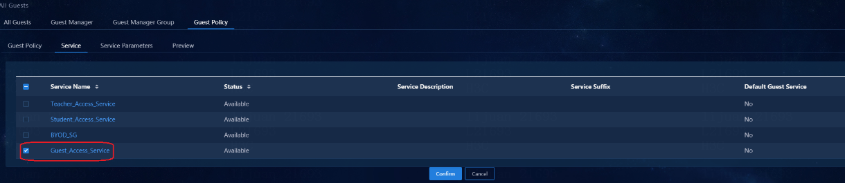
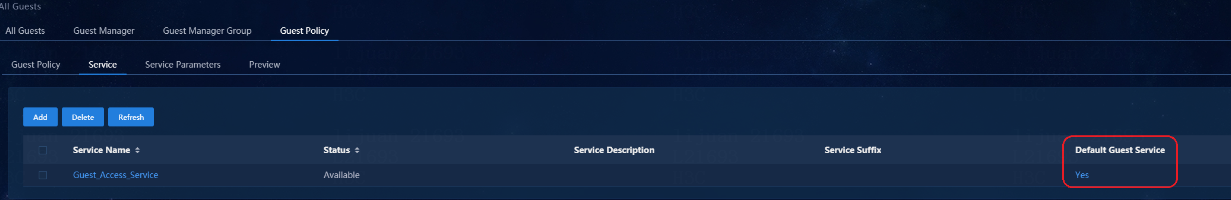
Configure a guest policy
Navigate to the Automation > User > Guest User > Guest Policy > Guest Policy page.
1. By default, the system has a default guest policy, as shown in the following figure.

2. Click ![]() to modify the
policy.
to modify the
policy.
Set Guest Auto-Registration to Enable. This setting enables a guest user to automatically come online after completing the pre-registration. If you disable this function, a guest user can come online only after the approval of the guest manager.
After setting Guest Auto-Registration to Enable, select the Apply to QR Code Registration and Authentication Users option. In this case, if QR Code Registration and Authentication is configured in "0Configure page push policy", a guest user is registered automatically by scanning the QR code without approval of the guest manager.
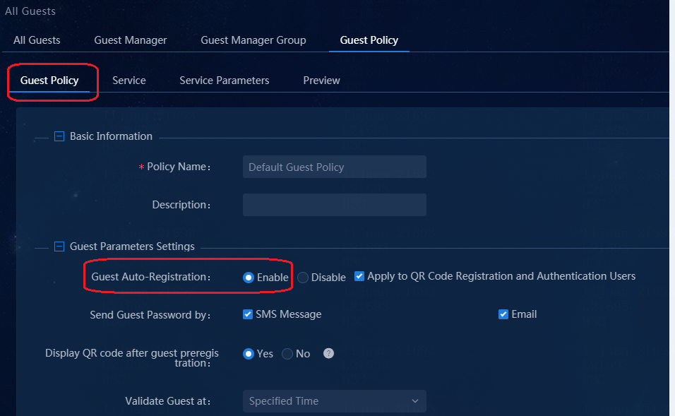
After the modification is completed, click OK.
Configure guest service parameters
Navigate to the Automation > User > Guest User > Guest Policy > Service Parameter Settings page.
You can use the default parameters or modify the settings as required. Once the settings are completed, the guest user can be authenticated to come online. For details about the configurations, see "0Guest ."
Configure page push policy
1. Navigate to the Automation > User > Access Service > Page Push Policy page.
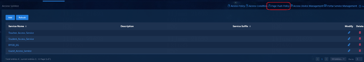
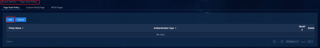
2. Click Add to open the page for adding push policies.
¡ Select Authentication Method as BYOD.
¡ The Default Authentication Page is PC-Default WEB Login (PC). You can set the authentication method as required.
After setting, click OK to save the configuration. You can view the new push policy on the page push policy list.
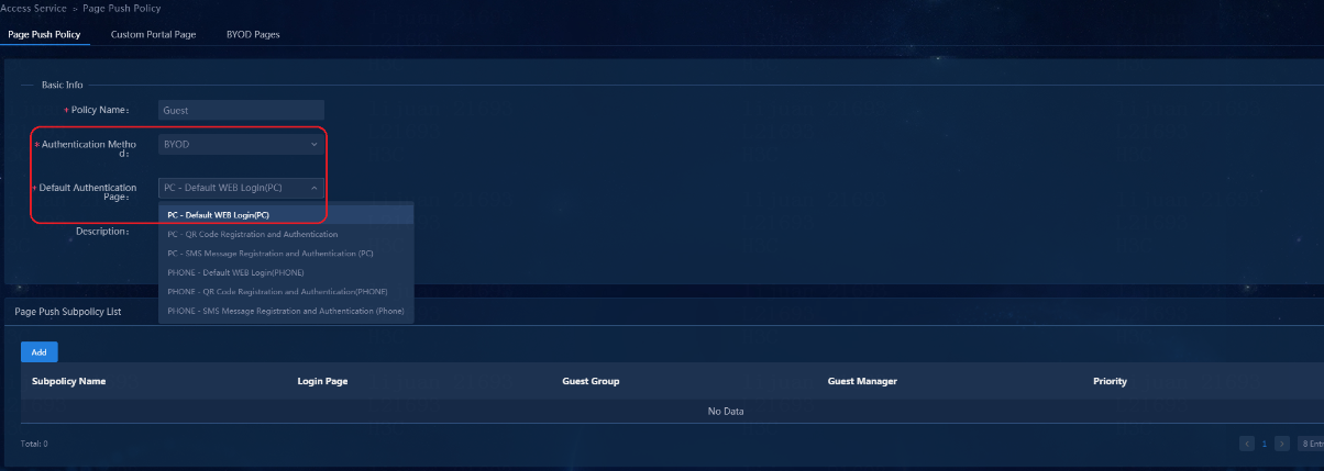
Guest access
User authentication and online
1. When an authentication device port is UP, MAC address authentication is triggered. Guests come online by using anonymous accounts. Byodanonymous come online. Navigate to the Monitor > Monitor List > User > Online Users page. The IP address is obtained from the network segment of the BYOD security group.
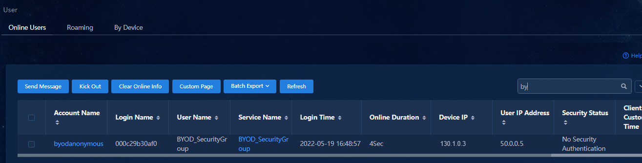
2. After a Web page is opened on the client, enter an IP address (any URL), such as 1.1.1.1.

Default web page
1. The default page push policy is Default WEB page, that is, the user's PC automatically jumps to the following BYOD default page: http://100.1.0.100:30004/byod/view/byod/byodLogin.html.
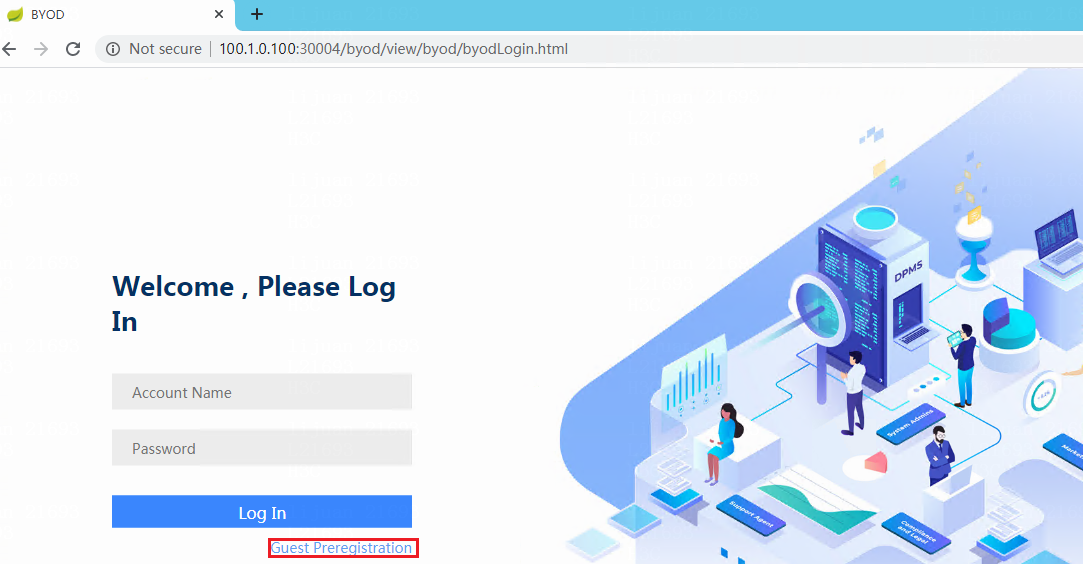
2. Click Guest Preregistration to open the following page, enter required fields marked with *, including Account Name, Identity Number, Verify Code, and Guest Manager. Click OK to complete the pre-registration.
The manager is the default manager set earlier. The password is randomly populated if not set. You can also set your own password.

3. If you register successfully, the registration result information is displayed. Click Login to log in directly, and click Return to go to the BYOD login page. Enter the registered account and password (guest2/123456) to log in.
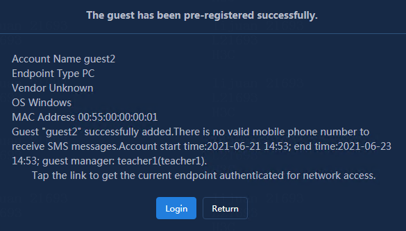
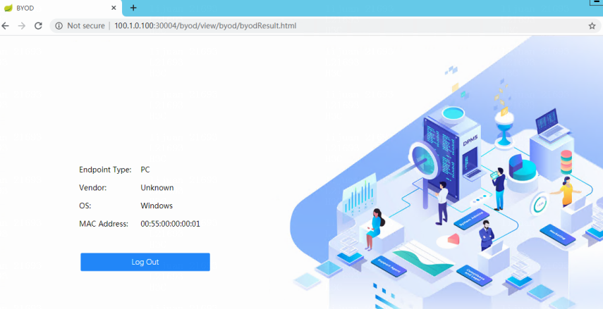
4. Navigate to Monitor > Monitor List > User > Online Users. You can view that guest2 successfully obtained an IP address in the guest security group.
5. Navigate to the Automation > User > Guest User > All Guests page. The guest user just registered is displayed. Click the account name to view the details of the registered guest user.
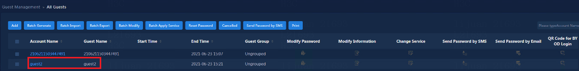
QR code registration and authentication
1. If you select PC-Default PC QR code authentication in the page push policy of "Configure page push policy", the QR code page is automatically displayed.
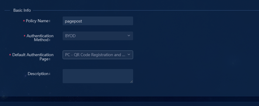
2. Modify the Default Guest Policy, and change the Guest Auto-Registration to prohibited. The guest user needs to be approved by the manager before the guest can come online.
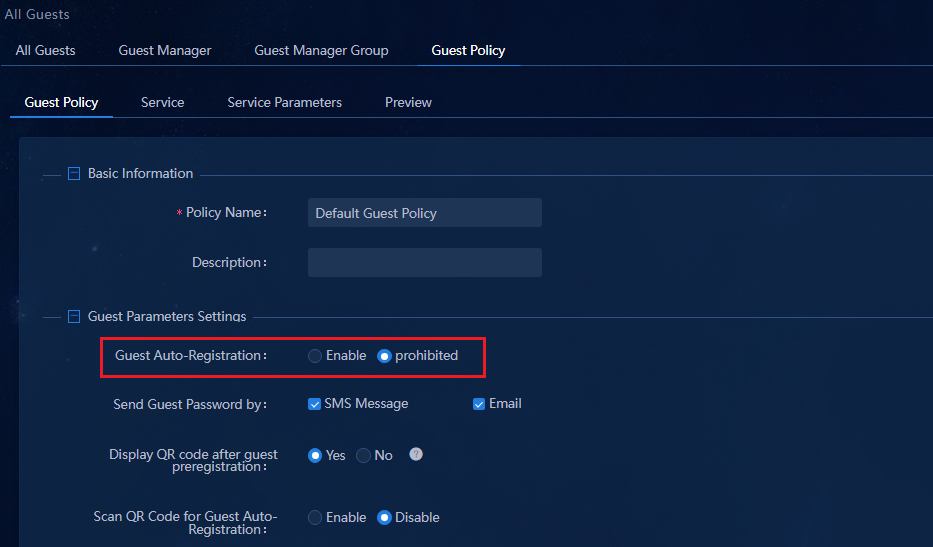
3. After the client PC authentication port is UP and enters the BYOD security group, enter any IP address on Google Chrome of the client PC. The QR code page opens as follows.

4. The guest manager can scan the QR code on this guest PC by a cell phone. Click Continue to access the login page.
If the cell phone is not connected to the same network as the client, enter the URL displayed on the cell phone on the PC. The following page opens. Log in by using the guest manager account (g01/123456).
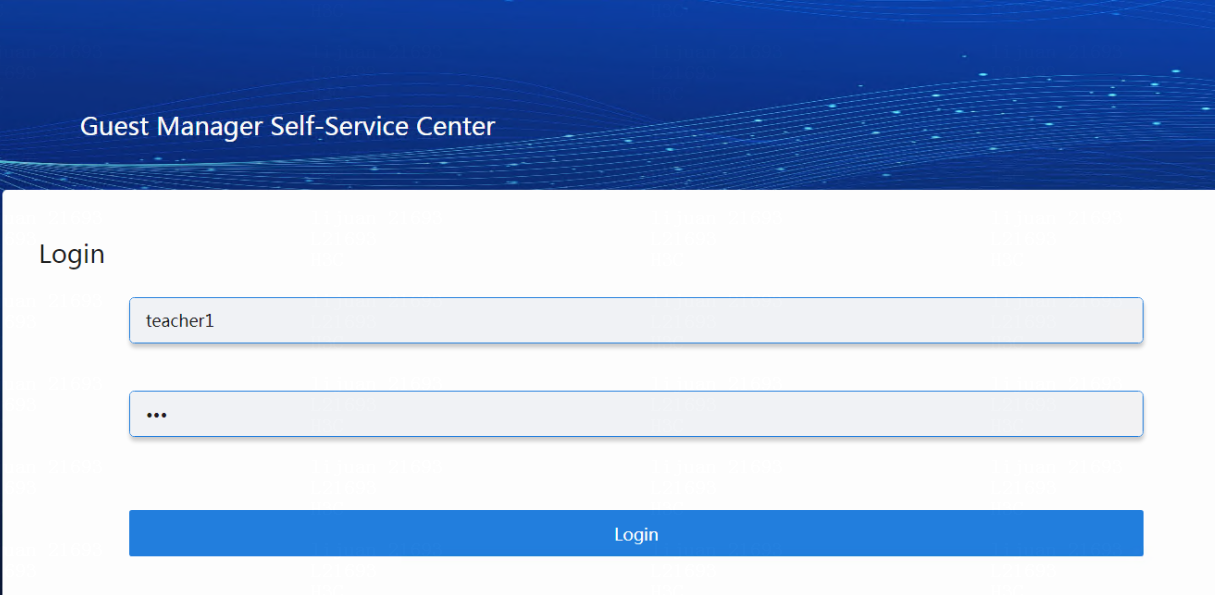
5. After login, the following page opens. The account shown below is the account given to the guest. The manager clicks To Approve to open the approval page.
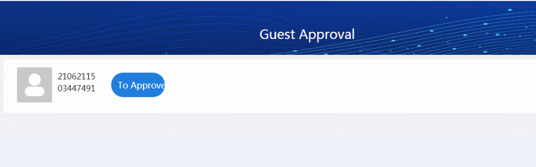
6. Click Pass to register the guest account. Then the approval page turns to the page of successful registration.
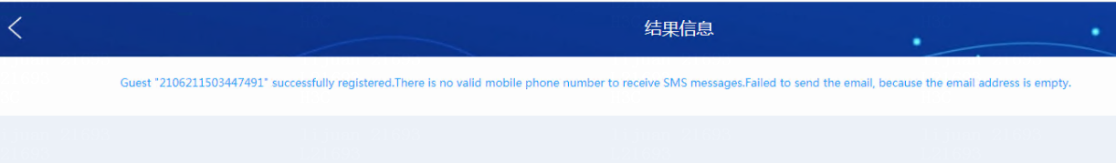
7. About 20 to 30 seconds later, the guest can automatically log in. The guest information of successful registration can be viewed on EIA. Navigate to Automation > User > Guest Management > All Guests. You can see that the user logs in to the guest access group and obtains an IP address from the IP segment of the guest access group.
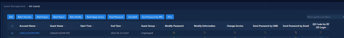
SMS message registration and authentication page
1. If you select PC - SMS Message Registration and Authentication on the "0Configure page push policy" page, the user's PC automatically jumps to the default SMS page.
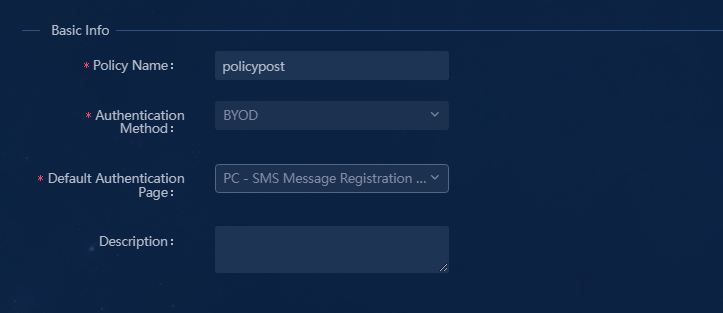
2. After the client PC authentication port is UP and enters the BYOD Access group, enter any IP address on Google Chrome of the client PC to enter the page as follows.
If an SMS Modem or SMS gateway is available, you can enter your cell phone number and then get a password to log in.
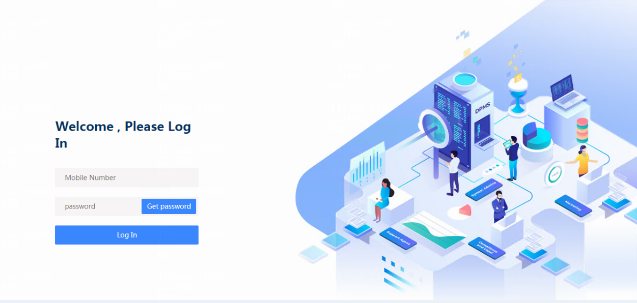
Scan QR code to log in
The manager sets a QR code for guest login, and the user only needs to scan the QR code to log in to the network and access the guest user's network resources.
1. The guest manager enters the IP address of the EIA server http://100.1.0.100:9066/ssvui/login.html in the browser to log in to the Self-Service Center page. Enter the guest manager's username and password. Click Login.
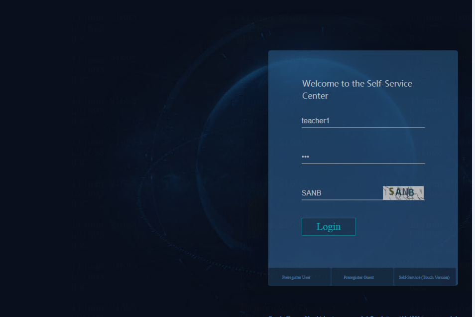
2. After logging in to the Self-Service Center, select Guest Management > All guests. The guest information is displayed.
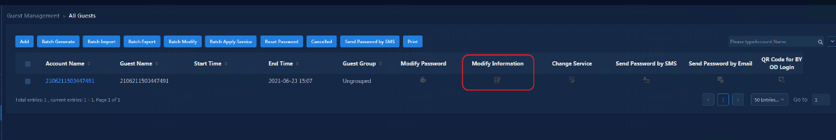
3. Click Add to add a guest or select a
guest in the guest list and click ![]() to modify the Max.
Concurrent Logins. Set the number of users allowed to scan the QR code
according to the actual demand. The maximum value is 999.
to modify the Max.
Concurrent Logins. Set the number of users allowed to scan the QR code
according to the actual demand. The maximum value is 999.
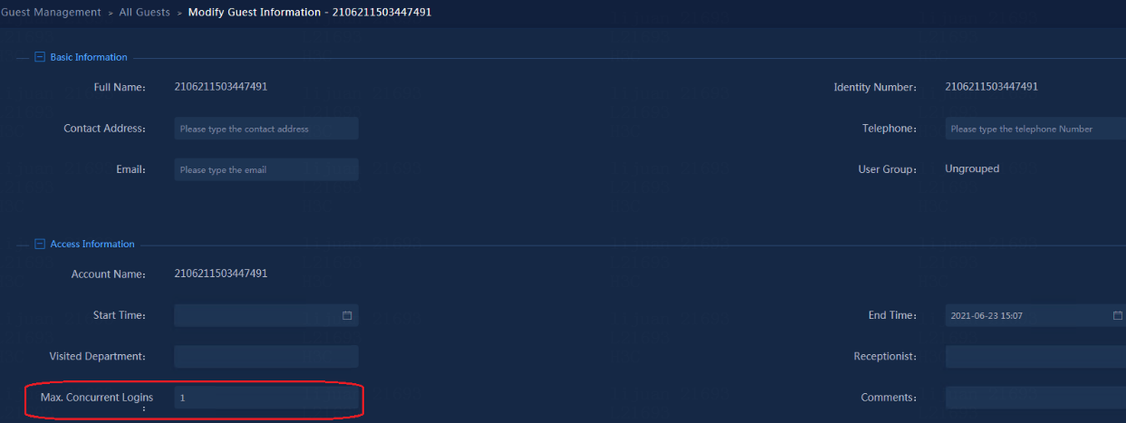
4. After Max. Concurrent Logins is set,
click ![]() to open
a QR code page. Users can scan the QR code to log in successfully.
to open
a QR code page. Users can scan the QR code to log in successfully.
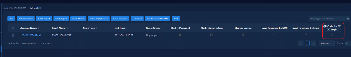
5. If you want to use the WeChat to scan the guest QR code to complete the login, perform the following in the case that the BYOD security group address cannot connect to the external network:
When the guest's cell phone is connected to the external network, use WeChat to scan the QR code generated by the manager to get the URL in the QR code.
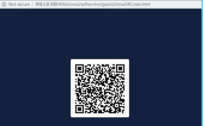
Approve guests
When Guest Auto-Registration is set to Disable in "Configure a guest policy", a guest needs to be approved by the guest manager. The guest can be an official guest user after approval.
1. The guest manager enters the IP address of the EIA server http://100.1.0.100:9066/ssvui/login.html in the browser to log in to the Self-Service Center page. Enter the guest manager's username and password. Click Login.
2. Navigate to Guest Management > All
Preregistered Guests to query all the guest users waiting for approval.
Click ![]() for approval.
for approval.
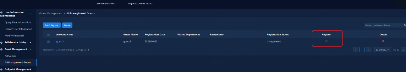
In the approval, you can modify the access users of guests. All access services configured in "Configure a guest service" are listed. Click Approve to pass the approval.
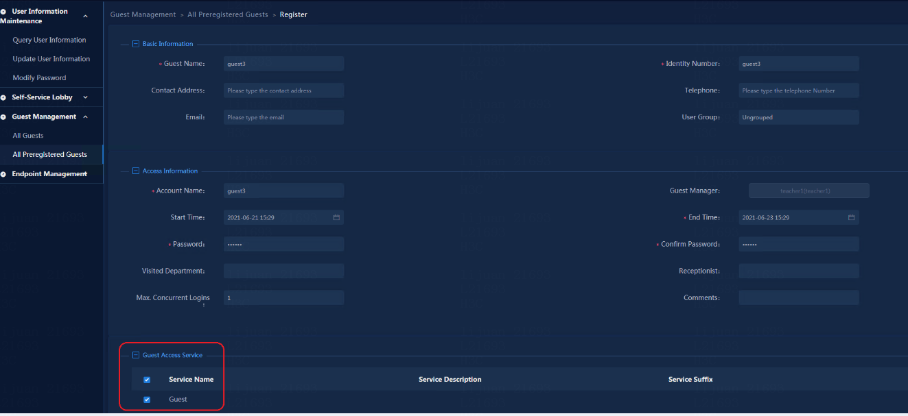
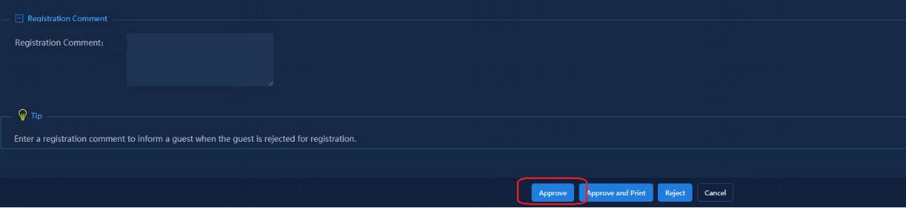
3. After approval, you can query the approved guest users on the Automation > User > Guest Management > All Guests page.
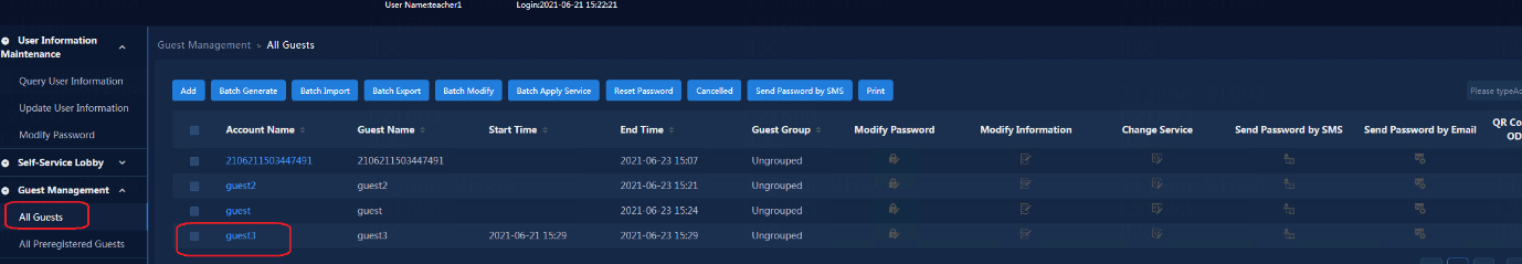
Configure direct connection between endpoints and leaf devices
Leaf interfaces can also directly connect to endpoints in addition to access devices, and endpoints are authenticated to come online by directly connecting to the leaf interfaces.
Add members to an interface group
1. Navigate to the Automation > Campus
Network > Device Groups > General Device Groups page, and
click ![]() in the Actions column for User Direct Access Interface Group for Leafs.
in the Actions column for User Direct Access Interface Group for Leafs.
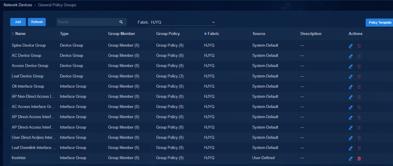
2. Click the Member tab, and click Add to open the page for adding interfaces. Select the interface connected to the endpoints on the Leaf devices. Click Add to add the interface to the list and click OK as shown below.
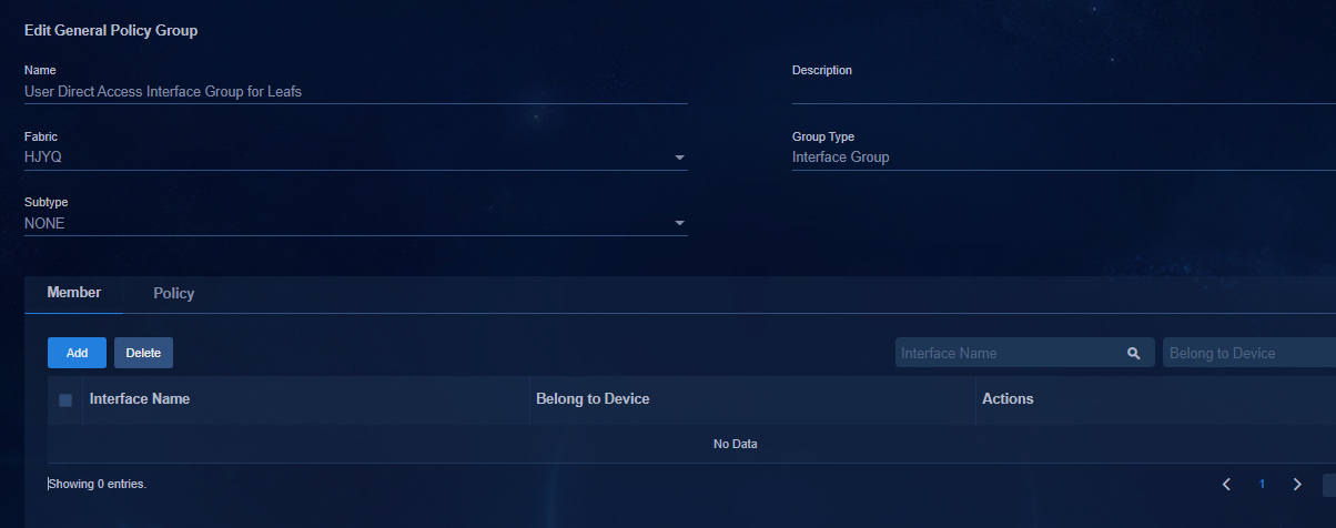
3. Click OK to complete the addition.
Configure an interface group deployment policy
1. Navigate to the Automation > Campus
Network > Devices > General Device Group page, and
click Add to add a security group, or click ![]() in the
Actions column. Click the Policy tab and select the custom policy
mode configured earlier to add to the group policy. Deliver the 802.1X
authentication template or MAC Portal authentication template according to the
actual situation.
in the
Actions column. Click the Policy tab and select the custom policy
mode configured earlier to add to the group policy. Deliver the 802.1X
authentication template or MAC Portal authentication template according to the
actual situation.
2. Select only one of the two methods. As a best practice, do not configure both 802.1X authentication and MAC Portal authentication on a physical interface.
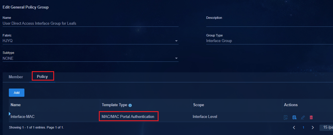
3. Deploy the configuration to the leaf device as follows:
Deploy 802.1X authentication or MAC/MAC Portal authentication settings based on the actual situation. Specify only one of the two authentication methods. Take MAC/MAC Portal authentication as an example.
//Interface of directly connected Leaf device.
#
interface Ten-GigabitEthernet 0/0/2
port link-mode bridge
port link-type trunk
port trunk permit vlan 1
mac-based ac
mac-authentication
mac-authentication domain hz1
mac-authentication parallel-with-dot1x
mac-authentication critical vsi vsi167 url-user-logoff
#
4. After the configuration is completed, the endpoints connected to the leaf device can be authenticated.
Configure fail-permit schemes
The fail-permit scheme is mainly used to allow users to access resources in a specific security group when the EIA server fails and user authentication cannot be connected to the EIA server. The specific security group is the fail-permit security group.
When configuring the fail-permit service, a DHCP server needs to be set up for the fail-permit service, and the subnet corresponding to the fail-permit security group is delivered to the fail-permit DHCP server. An H3C DHCP server or a third-party DHCP server can be used.
The microsegmentation solution provides dynamic AC authentication user fail-permit and static AC authentication user fail-permit.
· Dynamic AC authentication user fail-permit: An isolation domain supports only one fail-permit security group. Users in different private networks use the same fail-permit security group.
· Static AC authentication user fail-permit: The static AC user fail-permit is a new fail-permit feature for static AC authentication users. Each private network is configured with a fail-permit security group. The IP address of a user remains unchanged when the user is assigned to the fail-permit security group. The system determines the fail-permit security group for a user based on the private network to which the static AC that authenticates the user belongs.
|
|
IMPORTANT: · Fail-permit has two modes: dynamic AC authentication user fail-permit and static AC authentication user fail-permit. · An isolation domain supports only one fail-permit security group for dynamic AC users. When multiple isolation domains exist, you can configure a fail-permit security group for each domain or configure the domains to use the same fail-permit security group. · For static AC user fail-permit, each private network requires a fail-permit security group. · You must configure the fail-permit security group in the user's private network, and you cannot configure the fail-permit security group in the vpn-default. · The AD-Campus 6.0 solution requires configuring the fail-permit DHCP server. · The fail-permit DHCP server and the EIA server, BYOD DHCP server, and service DHCP server must be set up on different servers. Make sure that the fail-permit DHCP server and the device are interconnected. · If EAD is not used, do not select Enable the policy server as a best practice. (The system selects this option by default.) Otherwise, after the fail-permit time exceeds three heartbeat intervals, the online 802.1X user of the iNode client will automatically go offline. To configure the parameter, navigate to the Automation > User Service > Access Parameters > Policy Server Parameter Settings page. |
Create a fail-permit Layer 2 network domain
Navigate to the Automation > Campus Network > Private Network > Layer 2 Network Domain page. Click Add to open the Add Layer 2 Network Domain page, and configure the parameters as follows:
· Isolation domain: Select an isolation domain.
· Private Network: Select the private network. You should not select vpn-default.
· Type: Select Critical.
· IPv4 Address Allocation: Select Dynamic.
· DHCPv4 Server: Select the DHCP server for fail-permit. Set parameters according to the actual environment.
· IPv4 Address Lease Duration: The default setting is 10 minutes. As a best practice, use the default setting.
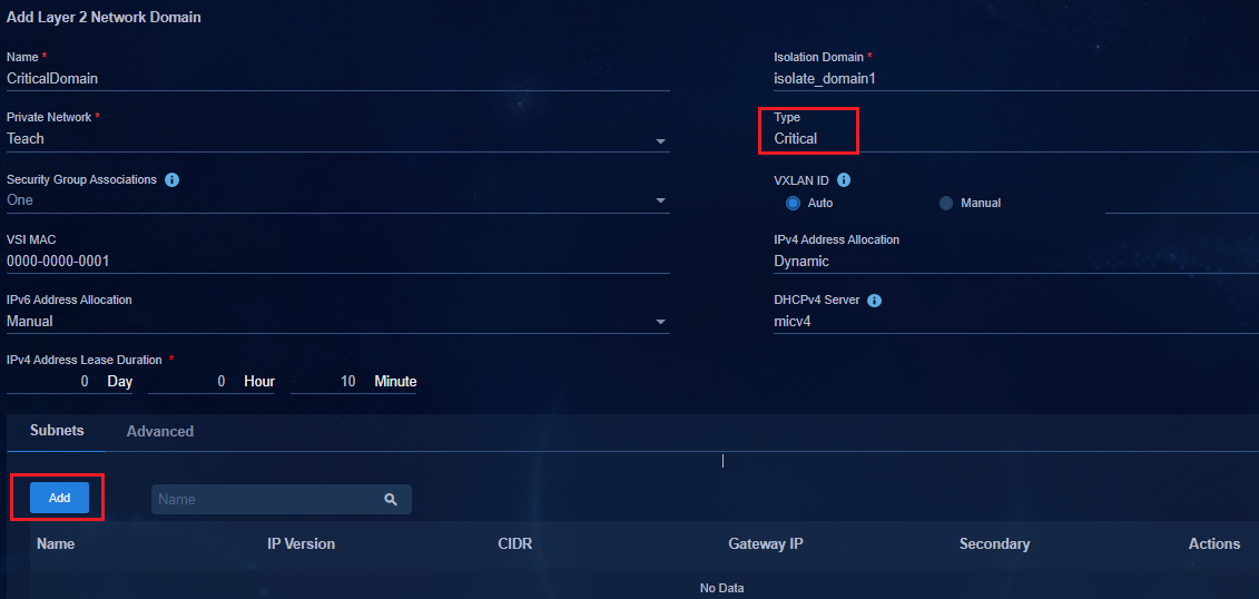
|
|
IMPORTANT: An isolation domain supports only one fail-permit Layer 2 network domain. The fail-permit Layer 2 network domain is applicable to dynamic AC authentication users. For fail-permit of static AC authentication users, you do not need to create a fail-permit Layer 2 network domain. |
Deploy the configuration to the leaf device:
# Configure the DHCP server IP address for the VSI interface of the leaf device as the IP address of the fail-permit server.
interface Vsi-interface7
description SDN_VSI_Interface_7
ip binding vpn-instance vpn1
ip address 52.0.0.1 255.255.0.0
mac-address 0000-0000-0001
local-proxy-arp enable
arp scan keepalive enable
arp fib-miss drop
dhcp select relay proxy
dhcp relay information circuit-id vxlan-port
dhcp relay information enable
dhcp relay server-address 8.0.0.171 //Specify the fail-permit DHCP server.
dhcp relay source-address interface Vsi-interface4094
dhcp relay request-from-tunnel discard
ipv6 nd scan keepalive enable
ipv6 nd fib-miss drop
distributed-gateway local
#
Create a fail-permit security group
Navigate to the Automation > Campus Network > Security Group > User Security Group page. Click Add to open the page for adding security groups.
· Private Network: Select a private network. For dynamic AC authentication fail-permit, select one private network. For static AC authentication fail-permit, each private network requiring fail-permit requires a fail-permit security group.
· Type: Select Critical.
· Isolation Domains: Select an isolation domain. If multiple isolation domains exist, you can select multiple isolation domains.
· Layer 2 Network Domain: For dynamic AC authentication fail-permit, select the added fail-permit Layer 2 network domain. For static AC authentication fail-permit, you do not need to set the Layer 2 network domain.
The following figure shows fail-permit for dynamic AC authentication.
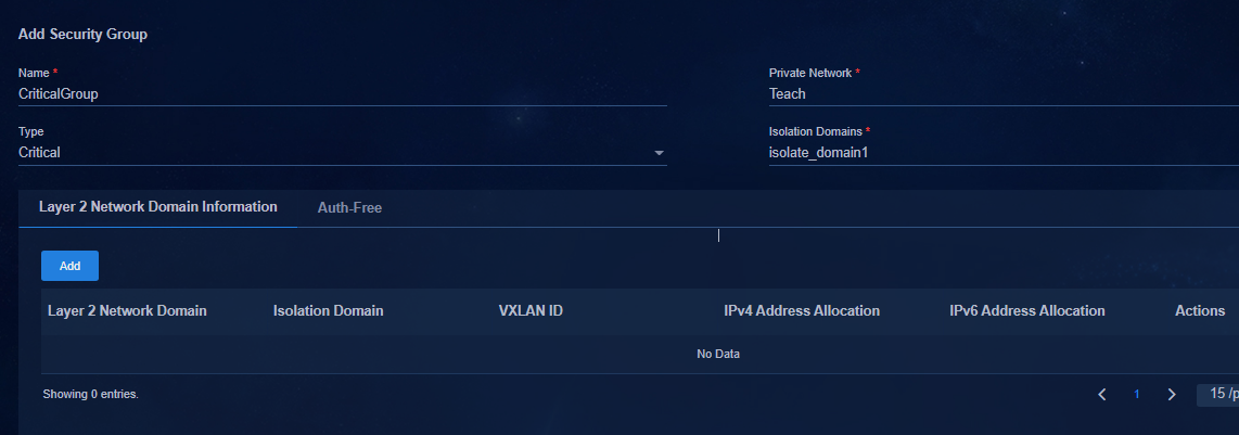
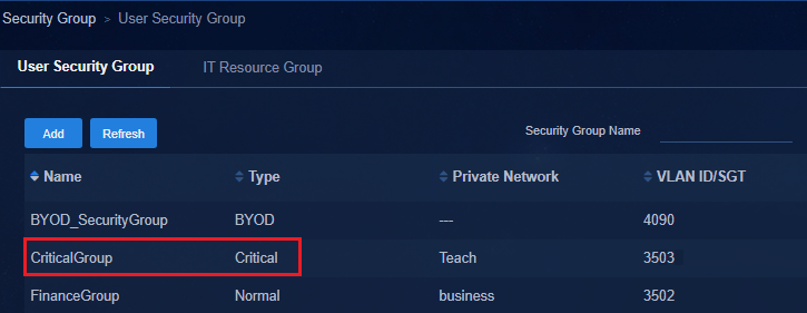
#Deploy microsegmentation configuration.
microsegment 3503 name SDN_EPG_3503
member ipv4 52.0.0.0 255.0.0.0 vpn-instance Teach
#
#Deploy the mapping between fail-permit and VXLAN.
radius scheme hz1
primary authentication 100.1.0.100 vpn-instance vpn-default
primary accounting 100.1.0.100 vpn-instance vpn-default
accounting-on enable send 255 interval 15
key authentication cipher $c$3$FXUDf5A1SBDyvwfeTdd0qCAAG2zCQQxibQ==
key accounting cipher $c$3$4E53VM7criBNRPyjrfoHpsHIO5Va2gyDxA==
timer realtime-accounting 15
user-name-format without-domain
vpn-instance vpn-default
attribute translate
stop-accounting-packet send-force
attribute convert H3c-User-Group to H3C-Microsegment-Id received
microsegment 3502 associate vsi vsi4
microsegment 3503 associate vsi vsi7
microsegment 3504 associate vsi vsi3
microsegment 3505 associate vsi vsi3
microsegment 4090 associate vsi vsi5
#
The following figure shows the static AC authentication fail-permit:
Static AC authentication fail-permit applies to users authenticated by static AC.
You need to configure a fail-permit security group for each private network that has static AC authentication. When configuring the fail-permit security group, you do not need to set the Layer 2 network domain.
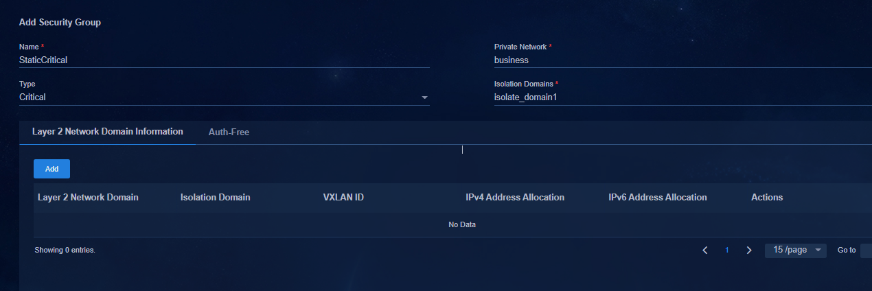
After the configuration is completed, the controller issues microsegmentation settings.
#
microsegment 3508 name SDN_EPG_3508
#
Configure fail-permit on leaf downlink interfaces
Set a policy template on the Automation > Campus Network > Devices > General Device Group > Policy Template page. The following sections describe the interface policy template configuration.
Interface policy template for 802.1X authentication
Select Yes for Enable The Escape Function.
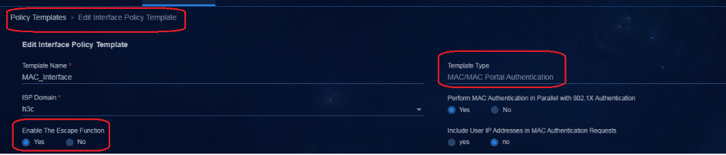
Interface policy template for MAC authentication
Select Yes for Enable The Escape Function.
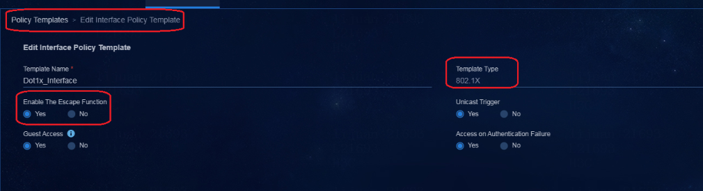
Deploy the policy template to the leaf downlink interface group
The previous sections describe configurations of fail-permit for 802.1X authentication and MAC authentication. Configure fail-permit for 802.1X authentication or MAC authentication as needed. This example deploys MAC authentication policy template to the leaf downlink interface group.
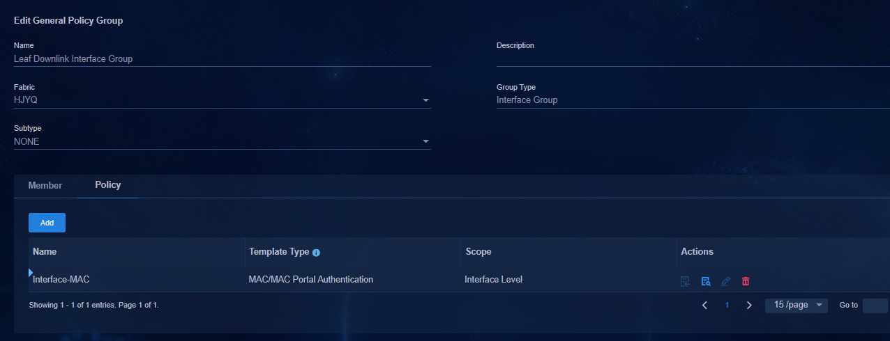
· Commands deployed by the controller to the leaf device:
#Deploy the fail-permit template configuration.
aaa critical-profile SDN_GLOBAL_CRITICAL_PROFILE
default critical-microsegment 3503 vsi vsi7 //Dynamic AC fail-permit.
if-match vpn-instance vpna critical-microsegment 3503 //Static AC fail-permit. This configuration is only issued on the private network of a Layer 2 network domain configured with static access.
if-match vpn-instance vpnb critical-microsegment 3508
#
# Deploy configuration to the downlink interface on the leaf device.
interface Bridge-Aggregation1024
port link-type trunk
port trunk permit vlan 1 101 to 3000 4093 to 4094
link-aggregation mode dynamic
stp tc-restriction
mac-based ac
mac-authentication
mac-authentication domain hz1
mac-authentication parallel-with-dot1x
mac-authentication critical profile SDN_GLOBAL_CRITICAL_PROFILE //MAC authentication fail-permit.
port-security free-vlan 1 4094
#
service-instance 2801
encapsulation s-vid 2801
xconnect vsi vsi13
#
service-instance 4094
encapsulation s-vid 4094
xconnect vsi vxlan4094
#
· If 802.1X authentication fail-permit is configured, the following configuration is deployed:
#
interface Bridge-Aggregation1024
port link-type trunk
port trunk permit vlan 1 101 to 3000 4093 to 4094
link-aggregation mode dynamic
stp tc-restriction
mac-based ac
dot1x
undo dot1x multicast-trigger
dot1x unicast-trigger
dot1x critical eapol
dot1X critical profile SDN_GLOBAL_CRITICAL_PROFILE//802.1X authentication fail-permit.
port-security free-vlan 1 4094
#
service-instance 2801
encapsulation s-vid 2801
xconnect vsi vsi13
#
service-instance 4094
encapsulation s-vid 4094
xconnect vsi vxlan4094
#
Configure fail-permit IT resource access settings
The fail-permit security group cannot be set in vpn-default. The fail-permit security groups configured in isolation domains are different. As a best practice, deploy some IT resource groups accessed by multiple private networks in the vpn-default private network. Then configure the IT resource group in the private network, and set the access permissions of the fail-permit security group and IT resource group.
By default, the private network can communicate with vpn-default. The private network can access the IT resource group associated with vpn-default regardless of whether the default access policy of the private network is Permit or Deny. Therefore, you need to configure the IT resource group in the private network, and then set the access policy of the IT resource group that the security group is not allowed to access. Deploy the deny group policy for the IT resource group that is not allowed to access, and prohibit the access to the resources.
Configure the fail-permit DHCP server
Configure a tightly coupled Microsoft DHCP server
If the fail-permit DHCP server is a Microsoft DHCP server, you need to configure VXLAN 4094 address pool. For the settings of DHCP server as Microsoft tight coupling, see the VXLAN 4094 address pool configuration in "Add a Microsoft DHCP server."
After the fail-permit security group is created, an address pool for the fail-permit service is created on the selected fail-permit DHCP server as follows.
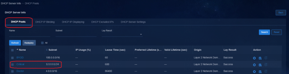
|
|
IMPORTANT: If multiple fabrics in an isolation domain exist, you need to configure the address pool of VXLAN 4094 for multiple fabrics. |
Configure a loosely coupled Microsoft DHCP server
In the case of loose coupling, the SeerEngine-Campus controller does not deploy any configuration to the DHCP server. You need to manually create the address pool of subnets in the fail-permit security group on the DHCP server.
Create a VLAN 4094 scope
Manually configure the scope of VLAN 4094 on the Microsoft DHCP server.
The purpose of configuring this address scope is to allow users to obtain IP addresses from the IP address pool in the fail-permit security group created later. If you do not configure the VLAN 4094 scope, users cannot obtain IP addresses from scopes created by other security groups.
|
|
IMPORTANT: If multiple fabrics exist in an isolation domain, you need to configure the address pool of VXLAN 4094 for multiple fabrics. |
1. Right-click and select New Scope to open the New Scope Wizard page. Enter the name.

2. Click Next to open the IP address range page. Enter the IP address range that is the same as the IP address range of VXLAN 4094/VLAN 4094 on the device.
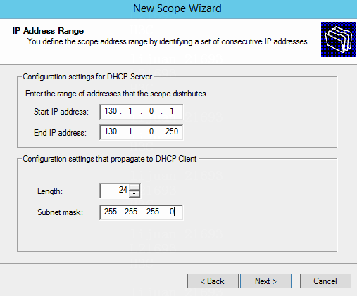
3. (Optional.) Click Next to specify the IP address range to be excluded. You can specify only the gateway IP. Click Add to add it to the list.
4. Click Next. Set the lease to one day.
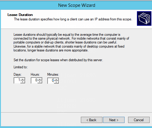
5. Click Next. On the scope activation page, activate the scope.
6. Click Next, and then click Finish to complete the configuration. The VLAN 4094 scope is configured as follows:
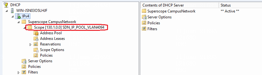
Create fail-permit security group scopes
1. Right-click and select New Scope to open the New Scope Wizard page on the Microsoft DHCP server.
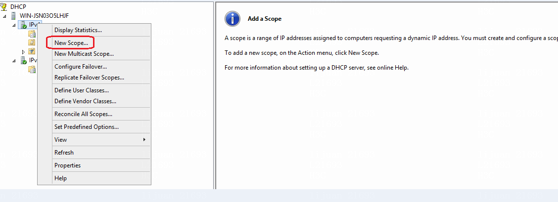
2. Enter the name and create a fail-permit security group.
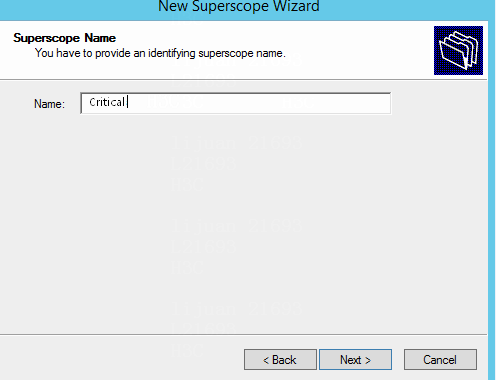
3. Click Add to open the IP address range page. Enter the IP range that is the same as the subnet as configured in "Create a fail-permit Layer 2 network domain."
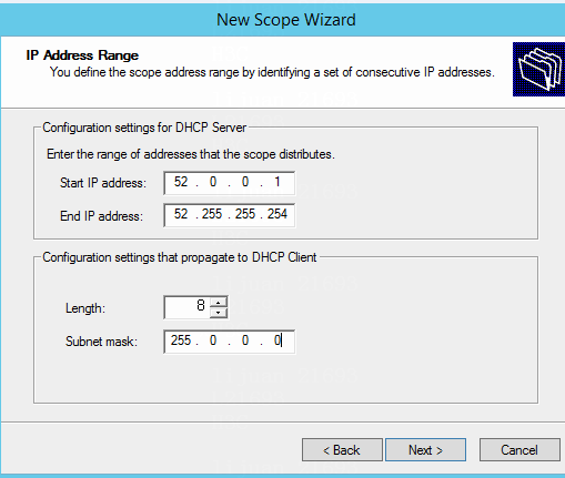
4. Click Next to open the Lease Duration page. Set the lease to 10 minutes as required by the fail-permit security group.
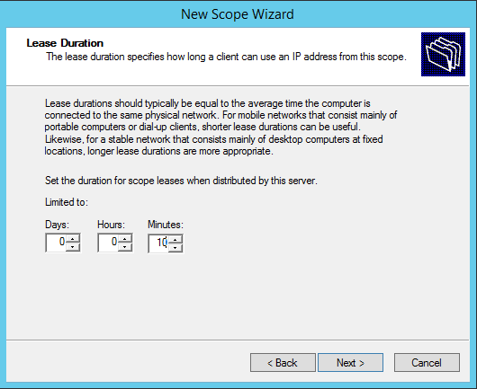
5. Click Next until you complete the configuration.
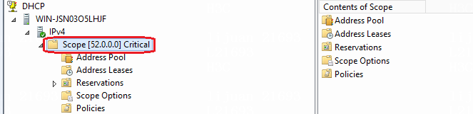
6. Then configure the policy of the scope. For information about other settings, see the scope policy configuration of VLAN 4094 (details not shown). Select the scope and right-click Policies in the Contents of Scope column to add a policy. Enter the policy name, and then click Next to open the policy condition page.
7. Click Add to open the Add/Edit Condition page to configure the policy condition. Select Relay Agent Information for Criteria and set Operator to Equals. The agent circuit ID is an ASCII code, starting with 30303030 and followed by VXLAN ID 30313637. It indicates that the VXLAN ID is 167, followed by * as the wildcard character to match any value. The VXLAN ID is the VXLAN ID of the fail-permit security group.

8. Click OK to save the configuration and click Next to enter the policy configuration page. Choose not to configure an IP address range for the policy.
9. Click Next to open the summary page. Click Finish to complete the configuration. The result is shown in the figure below.

Create a super scope
1. Right-click and select New Superscope to open the New Superscope Wizard page.
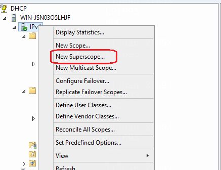
2. Click Next to open the Superscope Name page. Enter the name.
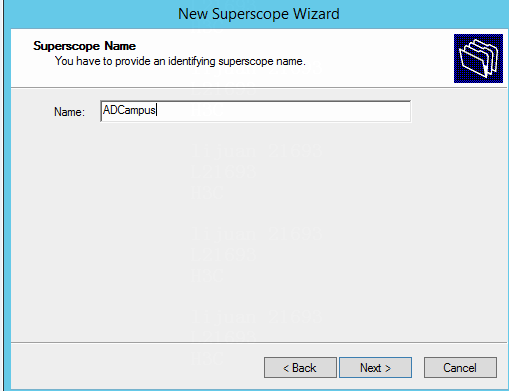
3. Click Next to open the Select Scopes page. Select the Critical scope and VLAN 4094 scope created previously.
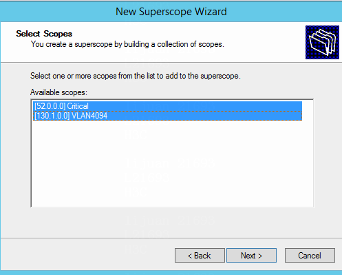
4. Click Next to complete the super scope configuration. You can see that the super scope contains the Critical scope and VLAN 4094 scope created previously.
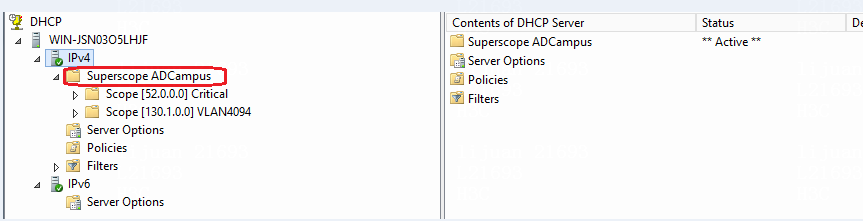
5. After the settings, all fail-permit plan configurations are completed. When the EIA server becomes faulty, users automatically enter the fail-permit security group and obtain the IP address of the fail-permit security group upon coming online.
IT resource group
Create an IT resource group
An IT resource group is used for authenticating user access to network resources. It controls access permissions of security group users to the server resources by deploying access policies.
|
|
IMPORTANT: The number of IP address entries is not limited in an IT resource group. As a best practice, add no more than 20 IP address entries to an IT resource group. |
1. Navigate to the Automation > Campus Network > Security Group > IT Resource Group page.
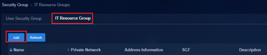
2. Click Add to open the page for adding a resource group. Enter the name, and select a private network to which the resource group belongs. Click Add Address Entry to add one or more subnets as resource entries.

3. Click OK to return to the page for adding a resource group. Click OK to save the configuration. The added IT resource group is displayed on the IT Resource Group page. A microsegment ID is assigned to each IT resource in the IT resource group.
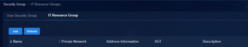
· Create four IT resource groups, and deploy the configuration to the device as follows:
#Create a microsegment for each resource group.
microsegment 60001 name SDN_EPG_60001
member ipv4 151.1.0.0 255.255.255.0 vpn-instance Teach
#
#
microsegment 60002 name SDN_EPG_60002
member ipv4 151.2.0.0 255.255.255.0 vpn-instance Teach
#
#
microsegment 60003 name SDN_EPG_60004
member ipv4 151.3.0.0 255.255.255.0 vpn-instance Teach
#
#
microsegment 60004 name SDN_EPG_60005
member ipv4 151.4.0.0 255.255.255.0 vpn-instance Teach
#
#Deploy the supernet iterative static routes.
ip route-static vpn-instance Teach 151.1.0.0 24 151.1.0.0 preference 200 recursive-lookup description SDN_ROUTE
ip route-static vpn-instance Teach 151.2.0.0 24 151.2.0.0 preference 200 recursive-lookup description SDN_ROUTE
ip route-static vpn-instance Teach 151.3.0.0 24 151.3.0.0 preference 200 recursive-lookup description SDN_ROUTE
ip route-static vpn-instance Teach 151.4.0.0 24 151.4.0.0 preference 200 recursive-lookup description SDN_ROUTE
#
Configure IT resource group access settings
As a best practice, mount the servers of the IT resource group on the spine device instead of the leaf device. This can avoid unnecessary traffic especially when multiple leaf devices exist in the network as shown in the following figure.
The spine device uses physical interface PortA to connect to the IT resource group. PortA is set to a static AC port.
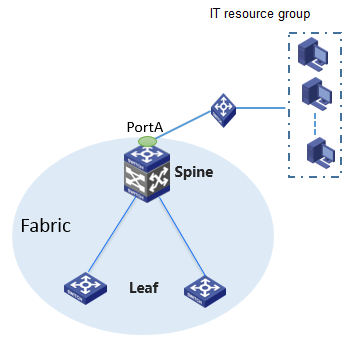
Navigate to the Automation > Campus Network > Network Strategy > Group Policies page. On the Group Policies tab, you can select Permit or Deny for the Default Policy setting of the private network in an inter-group policy.
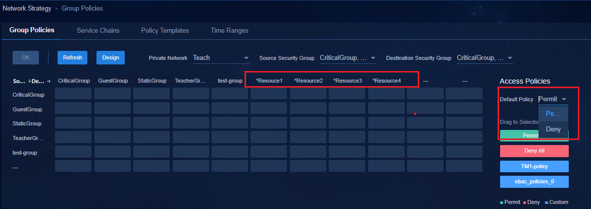
· Permit—All users in the private network can access the resources in the IT resource group. No inter-group policy is required for user access to IT resource groups. To prohibit users from accessing the IT resource group, configure a deny-mode inter-group policy.
· Deny—Users in the private network are not able to access the resources in the IT resource group by default. To enable users to access the IT resource group, configure a permit-mode inter-group policy. To prohibit users from accessing the IT resource group, you do not need to configure any policies.
As a best practice, connect public servers in the IT resource group through the spine device and deploy the servers in the vpn-default private network, regardless of the default access policy (Permit or Deny) for the private network.
When an IT resource group is deployed in the vpn-default private network, the security groups can access the IT resource group regardless of the default access policy (Permit or Deny) for the private networks. To prohibit access to an IT resource group from a private network, specify the IT resource group for the private network and deploy a deny-mode inter-group policy for the IT resource group.
Accessing external routers through a single border device
To enable online users in specific VPNs to communicate with external networks, configure a border device to redistribute external routes. In the current software version, you can specify a spine or any leaf device as the border device.
The figure below uses the spine device as the border device.
A private network can have one or multiple VPN instances. This example describes route configuration and deployment through the controller to enable a PC (at 20.0.0.3) in the private network to access the external network (at 20.1.1.0/24).
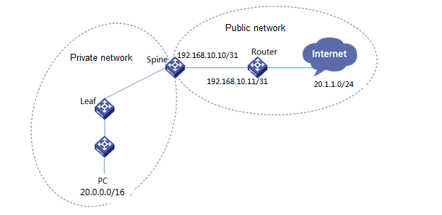
Create a border device group
1. Navigate to the Automation > Campus Network > Devices > Border Device Groups page.
2. Click Add to add border device group.
3. Select a fabric, and select Egress Gateway for Position.
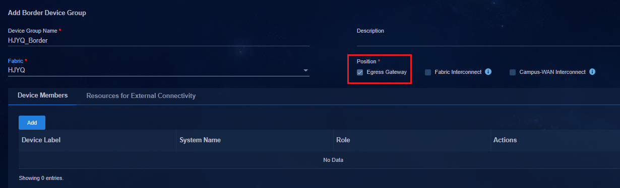
4. Select the Device Members tab and click Add. You can select a spine or leaf device as the border device group member. Specify a spine device as an example.
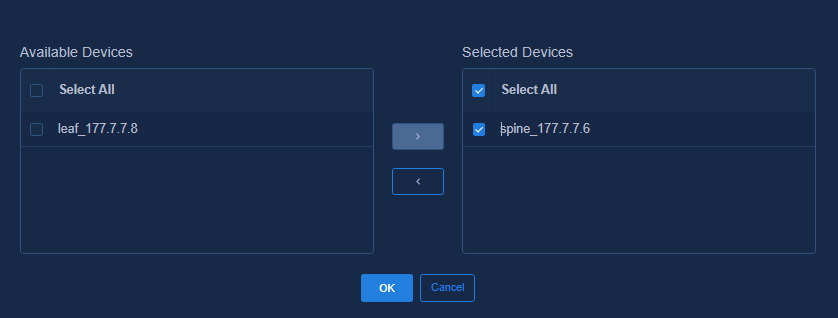
5. Click the Resources for External Connectivity tab to configure the egress network resources. You can specify the address pools and VLAN pools used for automatic allocation of network resources. The Campus Egress Address Pool and Campus Egress VLAN Pool settings must be configured in pairs for resource allocation when the campus communicates with the external network.
If you do not configure these settings, you must select Manual Configuration for Egress Network Resource Allocation Mode when adding an egress gateway member in "Add an egress gateway." The Security Egress Address Pool, Security Egress VLAN Pool, and Firewall Management Address Pool settings are used to configure the firewall network resource allocation. For more information about the configuration, see AD-Campus 6.2 Security Convergence Configuration Guide. This example describes only the campus egress gateway resource configuration.

6. Click Campus Egress Address Pool to select an existing address pool or create a campus egress address pool. Create a campus egress address pool for allocating local and remote IP addresses to egress network resources, and you can specify IPv4 or IPv6 addresses.
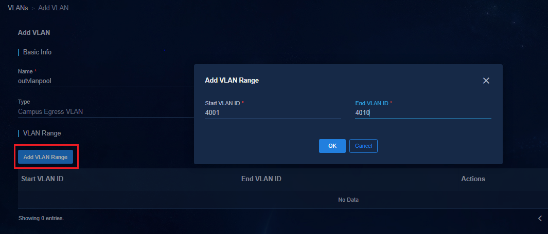
7. Click Campus Egress VLAN Pool to select an existing VLAN pool or create a campus egress VLAN pool. Create a campus egress VLAN pool for allocating VLANs to egress network resources for communication between the local and remote networks. The value range for a VLAN ID is 4001 to 4050.

8. Click OK. You can see the created border device group in the border device group list.
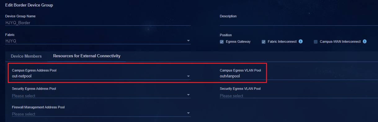
Add an egress gateway
1. Navigate to the Automation > Campus Network > Private Network > Export Gateway page, and click Add.
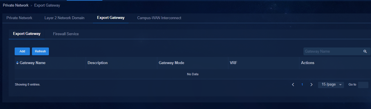
2. Configure the egress gateway mode as needed. Options are Public and Private.
¡ Public: A public gateway can be used by multiple private networks. Multiple private networks share an egress gateway.
¡ Private: A private gateway can be used by only one private network, and does not need to be created separately.
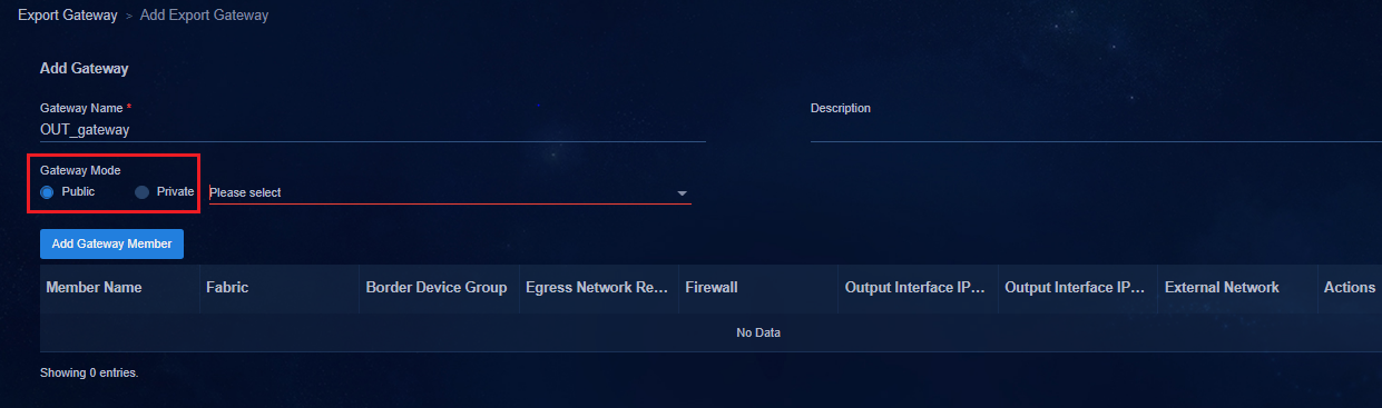
3. If you set Gateway Mode to Public, you need to create a VPN in the private network as the private network bound to the egress gateway.
4. To create a shared VRF, navigate to the Automation > Campus Network > Private Network > Private page. Select Yes for Share VRF.
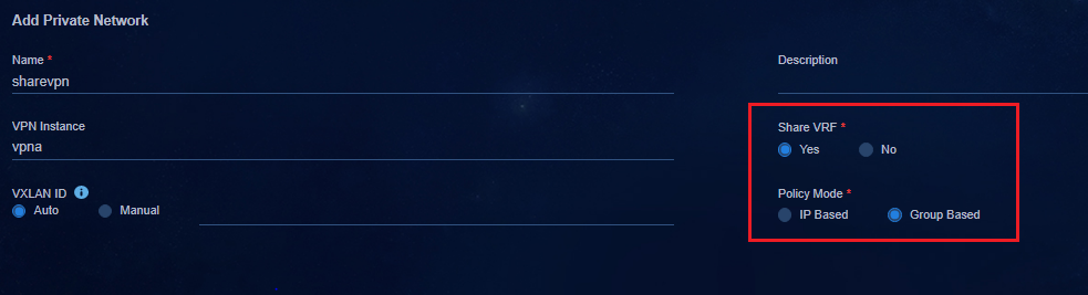
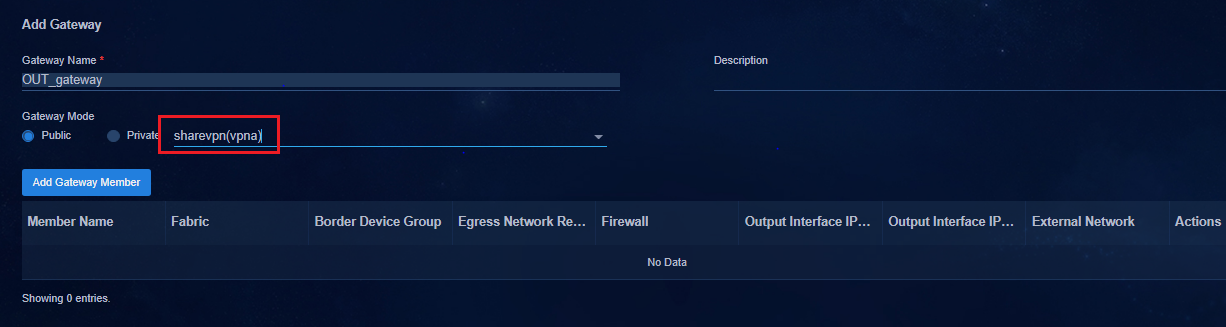
5. If you set Gateway Mode to Private, you do not need to configure a shared VRF.
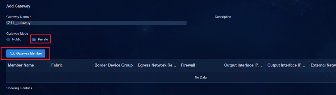
6. Click the previously configured border device group. Select Automatic Allocation or Manual Configuration.
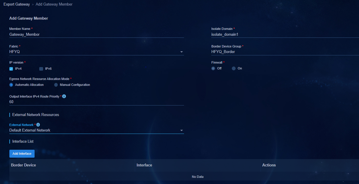
¡ External Network Resources: Select Default External Network or Add IT Resource Group. The Add IT Resource Group option is used for configuring the access to IT resources. The Default External Network option is used for configuring the access to the external network.
¡ Egress Network Resource Allocation Mode: Select Automatic Allocation or Manual Configuration.
- If you select Automatic Allocation, the controller automatically assigns VLANs, egress network segments, and remote network segments to the border device according to the settings configured in "0Create a border device group."
- If you select Manual Configuration, you need to manually configure the egress VLAN, egress network segment, and remote network segment. The remote network segment must be in the same network as the egress network segment.
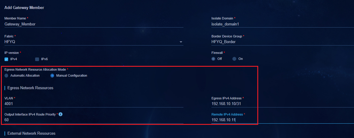
7. Click OK to return to the Add
Gateway page. Click ![]() in the Actions column for the gateway member to view the
VLAN and network segment information for communication between the border device
and external network.
in the Actions column for the gateway member to view the
VLAN and network segment information for communication between the border device
and external network.
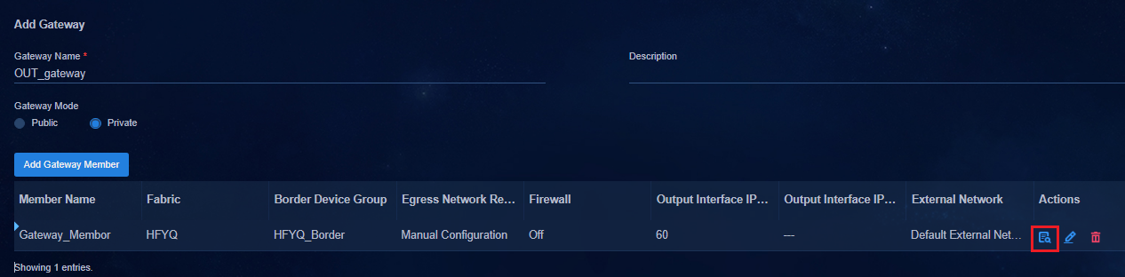
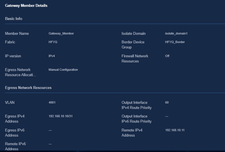
8. Click OK to view the created egress gateway in the gateway list.
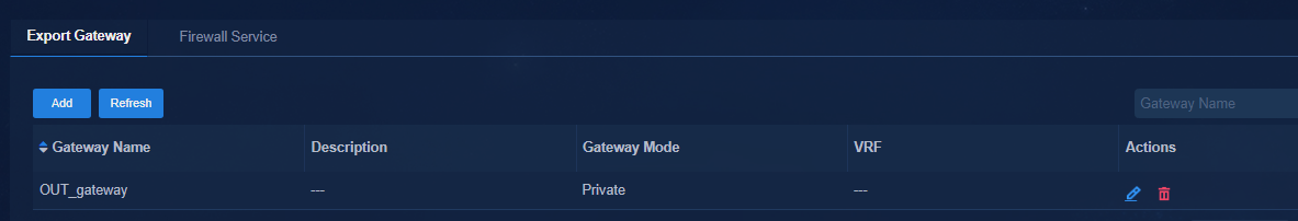
Associating the egress gateway with a private network
1. Navigate to the Automation > Campus Network > Private Network > Private Network page.
2. Click ![]() in the Actions
column for a private network.
in the Actions
column for a private network.
3. On the page that opens, configure the egress gateway in the private network used for external communication.
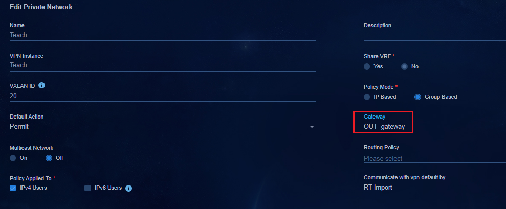
Egress gateway configuration deployed by the device
Public gateway
In this example, the egress gateway configured is a public gateway. The SeerEngine-Campus controller creates a VPN on the device. Users use the newly created VPN as the egress gateway instance for communication with the external network.
You can view the egress gateway configuration deployed by the controller on the spine device.
· Issue VLAN settings:
#
Vlan 4001
#
· Create a VPN instance:
#
ip vpn-instance VPNa
description SDN_VRF_fc248f21-f522-42b0-9882-cea78ee24a1dVPN1
#
address-family ipv4
route-replicate from vpn-instance vpn1 protocol direct //Replicate the private network route of VPN 1.
route-replicate from vpn-instance vpn1 protocol bgp 100
#
· Issue VLAN interface settings:
#
interface Vlan-interface4001
description SDN_VLAN_Interface_4001
ip binding vpn-instance VPNa //Bind shared gateway VPNa.
ip address 192.168.10.10 255,255,255,254
#
· Redistribute static routes to BGP:
#
bgp 100
#
ip vpn-instance vpn1
#
address-family ipv4 unicast
default-route imported //Redistribute static routes.
preference 240 240 130
import-route static
network 20.0.0.0 255.255.0.0
network 20.0.0.1 255.255.255.255
network 30.0.0.0 255.255.0.0
network 30.0.0.1 255.255.255.255
#
address-family ipv6 unicast
#
· Issue the default static route:
#
ip route-static vpn-instance vpn1 0.0.0.0 0 vpn-instance vpna 192.168.10.11 description SDN_ROUTE
#
Private gateway
You can view the egress gateway configuration deployed by the controller on the spine device.
· Issue VLAN settings:
#
Vlan 4001
#
· Issue VLAN interface settings:
#
interface Vlan-interface4001
description SDN_VLAN_Interface_4001
ip binding vpn-instance vpn1 //Bind VPN instance vpn1.
ip address 192.168.10.10 255,255,255,254
ip policy-based-route SDN_SC_VLAN_4001 //Apply a PBR policy.
#
#
policy-based-route SDN_SC_VLAN_4001 permit node 65535
if-match acl name SDN_ACL_SC_PERMIT_ALL
#
#
acl advanced name SDN_ACL_SC_PERMIT_ALL
description SDN_ACL_SC_PERMIT_ALL
rule 0 permit ip
#
· Configure a default route to the external network.
#
ip route-static vpn-instance vpn1 0.0.0.0 0 192.168.10.11 description SDN_ROUTE
#
Configure the interface connecting the border device to the external network
# If no interface is specified for the egress gateway member, you need to manually configure the interface. If an interface is specified, the controller automatically deploys the interface and you do not need to manually configure it.
interface Ten-GigabitEthernet1/5/0/32
port link-mode bridge
port link-type trunk
port trunk permit vlan 4001
#
Configure the L3 device connected to the border device
#
vlan 4001 //VLAN in egress gateway details.
#
#
interface Ten-GigabitEthernet1/0/9
port link-type trunk
port trunk permit vlan 4001
#
# Configure an IP address for communicating with the border device. //Remote IPv4 address in egress gateway details.
interface Vlan-interface 4001
ip address 192.168.10.11 255.255.0.0
#
Configure the default route to the public network. The next hop is the gateway address of the external network.
ip route-static 0.0.0.0 0 20.1.1.1
#
# For the route from the public network to the private network, you need to configure each network segment that communicates with the public network. The next hop is the border device.
#
ip route-static 20.0.0.0 16 192.168.10.10
ip route-static 30.0.0.0 16 192.168.10.10
#
Accessing external route devices through dual border devices
In the current software version, the controller does not support dual border egress configuration. You need to configure dual border egress manually as follows.
Configure Border1
· Create a VPN instance for the public egress:
#
ip vpn-instance VPNa
description SDN_VRF_GW
#
address-family ipv4
route-replicate from vpn-instance vpn1 protocol direct //Replicate the VPN route. When multiple private networks exist, you need to configure route replication for the private networks.
route-replicate from vpn-instance vpn1 protocol bgp 100
#
· Create a VLAN interface:
# VLAN 4001 is used for connection between border devices and external network egress.
Vlan 4001
#
#
interface Vlan-interface4001
description SDN_VLAN_Interface_4001
ip binding vpn-instance VPNa //Bind public gateway VPNa.
ip address 192.168.10.10 255,255,255,250
#
· Configure a permitted VLAN on the interface of the border device connected to the L3 device.
#
interface Ten-GigabitEthernet2/0/1
port link-type trunk
port trunk permit vlan 4001
#
· Redistribute default routes to BGP.
#
bgp 100
#
ip vpn-instance vpn1
#
address-family ipv4 unicast
default-route imported //Redistribute default routes.
preference 240 240 130
import-route static //Redistribute static routes.
network 20.0.0.0 255.255.0.0
network 20.0.0.1 255.255.255.255
network 30.0.0.0 255.255.0.0
network 30.0.0.1 255.255.255.255
#
address-family ipv6 unicast
#
· Configure VLAN-interface 4002 for the connection between border devices.
#
interface Vlan-interface4002
description to_border2_Interface_4002
ip binding vpn-instance VPNa //Bind public gateway VPNa.
ip address 192.168.10.12 255,255,255,250
#
· Configure permitted VLAN 4002 on the interface connecting border devices.
#
interface Ten-GigabitEthernet2/0/2
port link-type trunk
port trunk permit vlan 4002
#
· Configure NQA and Track.
# Associate NQA with the uplink of the border device.
nqa entry admin border1 //Specify the same admin username as the local user.
type icmp-echo
destination ip 192.168.10.11 //The destination IP address is the IP address of Layer 3 VLAN-interface 4001.
frequency 100
reaction 1 checked-element probe-fail threshold-type consecutive 3 action-type trigger-only
vpn-instance vpna //VPN bound to VLAN-interface 4001.
#
# Enable NQA.
nqa schedule admin border1 start-time now lifetime forever
#
# Associate NQA with the links of border devices
nqa entry admin border2 //Specify the same admin username as the local user.
type icmp-echo
destination ip 192.168.11.11 //The destination IP address is the IP address of Layer 3 VLAN-interface 4002.
frequency 100
reaction 2 checked-element probe-fail threshold-type consecutive 3 action-type trigger-only
vpn-instance vpna //VPN bound to the VLAN-interface 4002.
#
# Enable NQA.
nqa schedule admin border2 start-time now lifetime forever
#
# Configure Track and NQA association.
Track 1 nqa entry admin border1 reaction 1
#
#
Track 2 nqa entry admin spine1 reaction 2
#
· Configure static routes.
# Configure a static route from VPN 1 to the public network, and associate the static route with a track entry.
ip route-static vpn-instance vpn1 0.0.0.0 0 vpn-instance vpna 192.168.10.11 track 1
#
# Configure a backup static route from VPN 1 to the public network, with Border2 as the next hop.
ip route-static vpn-instance vpn1 0.0.0.0 0 vpn-instance vpna 192.168.11.11 track 2 preference 61
#
# Forward the packets from Border2 to Border1 to the public network.
ip route-static vpn-instance vpna 0.0.0.0 0 192.168.10.11
#
Configure Border2
· Create a VPN instance.
#
ip vpn-instance VPNa
description SDN_VRF_GW
#
address-family ipv4
route-replicate from vpn-instance vpn1 protocol direct //Replicate the private route of the VPN 1.
route-replicate from vpn-instance vpn1 protocol bgp 100
#
· Create a VLAN interface.
#
Vlan 4002
#
#
interface Vlan-interface4002
description SDN_VLAN_Interface_4002
ip binding vpn-instance VPNa //Bind public gateway VPNa.
ip address 192.168.11.10 255,255,255,250
#
· Configure a permitted VLAN on the interface of the border device connected to the L3 device.
#
interface Ten-GigabitEthernet2/0/1
port link-type trunk
port trunk permit vlan 4002
#
· Redistribute default routes to BGP.
#
bgp 100
#
ip vpn-instance vpn1
#
address-family ipv4 unicast
default-route imported //Redistribute default routes.
preference 240 240 130
import-route static //Redistribute static routes.
network 20.0.0.0 255.255.0.0
network 20.0.0.1 255.255.255.255
network 30.0.0.0 255.255.0.0
network 30.0.0.1 255.255.255.255
#
address-family ipv6 unicast
#
· Configure VLAN-interface 4001 connecting the border devices.
#
interface Vlan-interface4001
description to_border1_Interface_4001
ip binding vpn-instance VPNa //Bind public gateway VPNa.
ip address 192.168.10.12 255,255,255,250
#
· Configure permitted VLAN 3 on the interface connecting the border devices.
#
interface Ten-GigabitEthernet2/0/2
port link-type trunk
port trunk permit vlan 4001
#
· Configure NQA and Track.
# Associate NQA with the uplink of the border device.
nqa entry admin border2 //Specify the same admin username as the local user.
type icmp-echo
destination ip 192.168.11.11 //The destination IP address is the IP address of Layer 3 VLAN-interface 4002.
frequency 100
reaction 1 checked-element probe-fail threshold-type consecutive 3 action-type trigger-only
vpn-instance vpna //VPN bound to VLAN-interface 4002.
#
# Enable nqa.
nqa schedule admin border2 start-time now lifetime forever
#
# Configure nqa and connect the links of Border devices.
nqa entry admin border1 //Specify the same admin username as the local user.
type icmp-echo
destination ip 192.168.10.11 //The destination IP address is the IP address of Layer 3 VLAN-interface 4001.
frequency 100
reaction 2 checked-element probe-fail threshold-type consecutive 3 action-type trigger-only
vpn-instance vpna //VPN bound to VLAN-interface 4001.
#
# Enable NQA.
nqa schedule admin border1 start-time now lifetime forever
#
# Configure Track and NQA association.
Track 1 nqa entry admin border2 reaction 1
#
#
Track 2 nqa entry admin border1 reaction 2
#
· Configure static routes:
# Configure a static route from VPN 1 to the public network, and associate the static route with a track entry.
ip route-static vpn-instance vpn1 0.0.0.0 0 vpn-instance vpna 192.168.11.11 track 1
#
# Configure a backup static route from VPN 1 to the public network, with Border2 as the next hop.
ip route-static vpn-instance vpn1 0.0.0.0 0 vpn-instance vpna 192.168.10.11 track 2 preference 61
#
# Forward the packets from Border1 to Border2 to the public network.
ip route-static vpn-instance vpna 0.0.0.0 0 192.168.11.11
#
Configure the L3 device connected to the border device
· Create a VLAN interface.
#
Vlan 4001
#
#
interface Vlan-interface4001
description SDN_VLAN_Interface_4001
ip address 192.168.10.11 255,255,255,254
#
#
Vlan 4002
#
#
interface Vlan-interface4002
ip address 192.168.11.11 255,255,255,254
#
· Configure a permitted VLAN on the interface connected to the Border1.
#
interface Ten-GigabitEthernet2/0/1
port link-type trunk
port trunk permit vlan 4001
#
· Configure a permitted VLAN on the interface connected to the Border2.
#
interface Ten-GigabitEthernet2/0/2
port link-type trunk
port trunk permit vlan 4002
#
· Configure static routes.
# Configure a static route from the L3 device to the public network, with the public network gateway as the next hop.
ip route-static 0.0.0.0 0 21.1.0.1
#
# Configure static routes from the public network to the private network for all network segments that communicate with the public network. The next hops are Border1 and Border2.
#
ip route-static 20.0.0.0 16 192.168.10.10
#
ip route-static 20.0.0.0 16 192.168.11.10
#
ip route-static 30.0.0.0 16 192.168.10.10
#
ip route-static 30.0.0.0 16 192.168.11.10
#
Restrictions and guidelines for the two-tier network configuration
Single-leaf networking
In a single-leaf network, only one leaf device exists in the network. All endpoints are connected to this leaf through the access switch. The servers such as SeerEngine-Campus and DHCP server are also directly connected to this leaf. You need to add this leaf device to the Leaf device group. The leaf configuration is different from the traditional leaf configuration. This section describes only the configuration differences. For other configurations, see the previous sections in standard networking.
· Configuration 1: As the leaf device is enabled with DHCP snooping (spine device is not enabled with DHCP snooping), you need to add DHCP snooping trusted port to the service instance connected to the DHCP server.
#
interface Ten-GigabitEthernet2/2/0/5
port link-mode bridge
port link-type trunk
port trunk permit vlan 1 4094
service-instance 4094
encapsulation s-vid 4094
xconnect vsi vxlan4094
dhcp snooping trust
#
· Configuration 2: As only one leaf exists in the network, you do not need to establish BGP peers. If a custom private network exists, you need to configure inter-VPN route redistribution as follows:
¡ Method 1:
#
bgp 100
non-stop-routing
address-family l2vpn evpn
#
ip vpn-instance vpn-default
#
address-family ipv4 unicast
import-route static
import-route direct
#
#
ip vpn-instance Teach
#
address-family ipv4 unicast
import-route static
import-route direct
#
#
¡ Method 2:
#
ip vpn-instance vpn-default
route-distinguisher 1:1
vpn-target 1:1 1:4 import-extcommunity
vpn-target 1:1 export-extcommunity
#
address-family ipv4
route-replicate from vpn-instance vpn1 protocol direct //Import the direct route of VPN 1 instance to vpn-default instance. Perform this operation multiple times if multiple VPNs exist.
#
address-family evpn
vpn-target 1:1 1:4 import-extcommunity
vpn-target 1:1 export-extcommunity
#
ip vpn-instance Teach
route-distinguisher 1:4
vpn-target 1:1 1:4 import-extcommunity
vpn-target 1:4 export-extcommunity
#
address-family ipv4
route-replicate from vpn-instance vpn-default protocol direct
//Import only the direct route of vpn-default. Perform similar configuration for communication with other VPNs.
#
address-family evpn
vpn-target 1:1 1:4 import-extcommunity
vpn-target 1:4 export-extcommunity
#
· Configuration 3: On the leaf, configure the following STP settings:
#
stp ignored vlan 2 to 4094
stp global enable
stp root primary
#
# On the leaf downlink interface, configure the stp tc-restriction command.
stp tc-restriction
#
Multi-leaf networking
Multi-leaf networking applies to cross-campus networks. The core devices (route reflectors) connected to servers (such as SeerEngine-Campus) also need to be added to the leaf device group, and make sure they have the same configuration as other leaf devices.
To ensure correct operation of this special networking, you need to add additional settings as described in the section. For other settings, see the standard networking configuration.
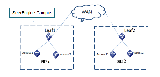
#
interface Vsi-interface4094
ip binding vpn-instance vpn-default
ip address 130.0.3.1 255.255.255.0
local-proxy-arp enable // Configure ARP proxy
#
· Additional configuration 1: Since the leaf device is enabled with DHCP snooping (the spine device is not enabled with this function), you need to add a DHCP snooping trusted port to the service instance connected to the DHCP server.
#
interface Ten-GigabitEthernet2/2/0/5
port link-mode bridge
port link-type trunk
port trunk permit vlan 1 4094
service-instance 4094
encapsulation s-vid 4094
xconnect vsi vxlan4094
dhcp snooping trust
#
· Additional configuration 2: The endpoints (in custom VPNs) on the core device connected to the server require communication with the server in the vpn-default or the external network. You need to import direct routes to the BGP VPN instance of the core device connected to the server.
#
bgp 100
#
ip vpn-instance vpn-default
#
address-family ipv4 unicast
import-route direct
#
ip vpn-instance vpn1
#
address-family ipv4 unicast
import-route direct
#
· Additional configuration 3: Configure each leaf as follows:
#
stp ignored vlan 2 to 4094
stp global enable
stp root primary
#
# On the leaf downlink interface, configure the stp tc-restriction command.
stp tc-restriction
#
Configure dual spine uplink
The AD-Campus solution supports dual spine uplink for redundancy and load sharing purposes.
Figure 15 Dual-spine networking
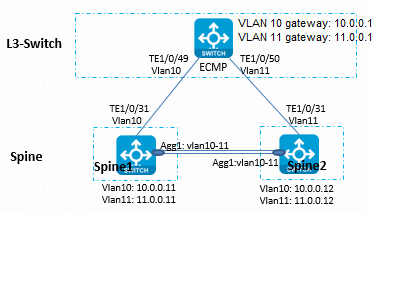
Table 10 IP addresses for the interfaces connecting the spines and L3 device
|
Device type |
Interface |
IP address |
Connected device |
Interface |
IP address |
|
Spine1 |
TE2/0/31 |
10.0.0.11 |
Layer 3 switch |
TE1/0/49 |
10.0.0.1 |
|
Spine2 |
TE2/0/31 |
11.0.0.12 |
Layer 3 switch |
TE1/0/50 |
11.0.0.1 |
|
Spine1 |
Aggr1 (VLAN 10, VLAN 11) |
10.0.0.11 11.0.0.11 |
Spine2 |
Aggr1 (VLAN 10, VLAN 11) |
10.0.0.12 11.0.0.12 |
Dual spine uplinks connect to the Layer 3 switch. ECMP is implemented by configuring equal-cost default routes to the two spine devices on the L3 switch. This section describes only the configuration specific to the dual spine uplink networking. For other settings, see 0"Manually incorporate a device" in this document.
Configure the Layer 3 switch
Create VLAN 10 and VLAN 11.
#
vlan 10 to 11
#
Configure STP.
#
stp global enable
#
# Configure VLAN 10 and VLAN 11 connected to the spine device as ignored VLANs.
stp ignored vlan 10 to 11
#
Create VLAN interfaces for VLAN 10 and VLAN 11.
#
interface Vlan-interface10
ip address 10.0.0.1 255.255.255.0
#
interface Vlan-interface11
ip address 11.0.0.1 255.255.255.0
#
Permit VLAN 10 on the interface connected to Spine1.
#
interface Ten-GigabitEthernet1/0/25
port link-mode bridge
port link-type trunk
undo port trunk permit vlan 1
port trunk permit vlan 10 //Configure permitted VLANs based on the actual networking.
#
Permit VLAN 11 on the interface connected to Spine2.
#
interface Ten-GigabitEthernet1/0/26
port link-mode bridge
port link-type trunk
undo port trunk permit vlan 1
port trunk permit vlan 11 //Configure permitted VLANs based on the actual networking.
#
Configure Track.
#
track 1 interface Ten-GigabitEthernet1/0/49 physical
track 2 interface Ten-GigabitEthernet1/0/50 physical
#
Configure two default routes. The next hops are the IP addresses of Spine1 and Spine2.
#
ip route-static 0.0.0.0 0 10.0.0.11 track 1
ip route-static 0.0.0.0 0 11.0.0.12 track 2
#
Configure 32-bit host routes to Spine1 or Spine2 to avoid traffic switchover upon link failure between the spines.
#
ip route-static 130.1.0.101 32 10.0.0.11 //130.1.0.101 is the IP address of VSI-interface 4094 on Spine1.
ip route-static 130.1.0.102 32 11.0.0.12 //130.1.0.102 is the IP address of VSI-interface 4094 on Spine2.
#
Connection between Spine1 and L3 Switch
Configure STP.
#
stp instance 0 root primary
stp ignored vlan 2 to 4094
stp global enable
#
Create VLAN 10.
#
Vlan 10
#
Configure VLAN-interface 10 and bind it to vpn-default.
#
interface Vlan-interface10
ip binding vpn-instance vpn-default
ip address 10.0.0.11 255.255.255.0
#
Permit VLAN 10 on the interface connecting L3 Switch.
#
interface Ten-GigabitEthernet2/0/31
port link-mode bridge
port link-type trunk
undo port trunk permit vlan 1
port trunk permit vlan 10 //Configure permitted VLANs based on the actual networking.
#
Configure the route to the server. The next hop is the IP address of L3 Switch.
#
ip route-static vpn-instance vpn-default 100.1.0.0 24 10.0.0.1
ip route-static vpn-instance vpn-default 110.1.0.0 24 11.0.0.1
#
Connection between Spine2 and L3 Switch
Configure the STP.
#
stp instance 0 root secondary
stp ignored vlan 2 to 4094
stp global enable
#
Create VLAN 11.
#
Vlan 11
#
Configure VLAN-interface 11 and bind it to vpn-default.
#
interface Vlan-interface11
ip binding vpn-instance vpn-default
ip address 11.0.0.12 255.255.255.0
#
Permit VLAN 11 on the interface connecting L3 Switch.
#
interface Ten-GigabitEthernet2/0/31
port link-mode bridge
port link-type trunk
undo port trunk permit vlan 1
port trunk permit vlan 11 //Configure permitted VLANs based on the actual networking.
#
Configure the routes to the servers, with the IP address of L3 Switch as the next hop.
#
ip route-static vpn-instance vpn-default 100.1.0.0 24 11.0.0.1
ip route-static vpn-instance vpn-default 110.1.0.0 24 11.0.0.1
#
Connection between Spine1 and Spine2
Configure Spine1
Configure fast reroute (FRR).
#
ip route-static fast-reroute auto
#
Create VLAN 11.
#
Vlan 11
#
# Create VLAN-interface 11.
#
interface Vlan-interface11
ip binding vpn-instance vpn-default
ip address 11.0.0.11 255.255.255.0
#
Create VLAN 3 for communication with Underlay.
#
Vlan 3
#
# Create VLAN-interface 3.
#
interface Vlan-interface3
ip address 3.0.0.1 255.255.255.0
ospf network-type p2p
ospf 1 area 0.0.0.0
#
Create an aggregation group.
#
interface Bridge-Aggregation1
link-aggregation mode dynamic
#
Add a port to the aggregation group.
#
interface Ten-GigabitEthernet1/0/30
port link-mode bridge
port link-aggregation group 1
#
interface Ten-GigabitEthernet2/0/30
port link-mode bridge
port link-aggregation group 1
#
Configure the aggregation group to permit VLAN 10, VLAN 11, and VLAN 3.
#
interface Bridge-Aggregation1
port link-type trunk
undo port trunk permit vlan 1 //Configure permitted VLANs based on the actual networking.
port trunk permit vlan 3 10 to 11
link-aggregation mode dynamic
#
//If FRR is configured, you do not need to configure NQA and Track.
Configure Track for fast route switchover upon failure of the physical link between spine devices.
#
track 1 interface Bridge-Aggregation1 physical
#
Configure a static route to Spine2 VXLAN 4094 (the next hop can belong to VLAN 10 or VLAN 11).
#
ip route-static vpn-instance vpn-default 130.1.0.102 32 11.0.0.12 track 1
#
Configure NQA and Track. Configure static routes to the server cluster, with gateway IP addresses of VLAN 10 and VLAN 11 on the L3 switch as the next hops, and associate the static routes with Track.
#
nqa entry admin server1
type icmp-echo
destination ip 10.0.0.1
frequency 100
reaction 3 checked-element probe-fail threshold-type consecutive 3 action-type trigger-only
vpn-instance vpn-default
#
nqa entry admin server2
type icmp-echo
destination ip 11.0.0.1
frequency 100
reaction 4 checked-element probe-fail threshold-type consecutive 3 action-type trigger-only
vpn-instance vpn-default
#
nqa schedule admin server1 start-time now lifetime forever
nqa schedule admin server2 start-time now lifetime forever
#
track 3 nqa entry admin server1 reaction 3
track 4 nqa entry admin server2 reaction 4
#
#
ip route-static vpn-instance vpn-default 100.1.0.0 24 10.0.0.1 track 3
ip route-static vpn-instance vpn-default 100.1.0.0 24 11.0.0.1 track 4 preference 61
ip route-static vpn-instance vpn-default 110.1.0.0 24 10.0.0.1 track 3
ip route-static vpn-instance vpn-default 110.1.0.0 24 11.0.0.1 track 4 preference 61
#
//Configure static routes when NQA and Track is not configured.
#
ip route-static vpn-instance vpn-default 100.1.0.0 24 10.0.0.1
ip route-static vpn-instance vpn-default 100.1.0.0 24 11.0.0.1 preference 61
ip route-static vpn-instance vpn-default 110.1.0.0 24 10.0.0.1
ip route-static vpn-instance vpn-default 110.1.0.0 24 11.0.0.1 preference 61
#
Import static routes to BGP vpn-default.
#
bgp 100
#
ip vpn-instance vpn-default
#
address-family ipv4 unicast
import-route direct
import-route static
#
Configure Spine2
Configure FRR.
#
ip route-static fast-reroute auto
#
Create VLAN 10.
#
Vlan 10
#
# Create VLAN-interface 10.
#
interface Vlan-interface11
ip binding vpn-instance vpn-default
ip address 10.0.0.12 255.255.255.0
#
Create VLAN 3 for communication with Underlay.
#
Vlan 3
#
# Create VLAN-interface 3.
#
interface Vlan-interface3
ip address 3.0.0.2 255.255.255.0
ospf network-type p2p
ospf 1 area 0.0.0.0
#
Create an aggregation group.
#
interface Bridge-Aggregation1
link-aggregation mode dynamic
#
Add a port to an aggregation group.
#
interface Ten-GigabitEthernet1/0/30
port link-mode bridge
port link-aggregation group 1
#
interface Ten-GigabitEthernet2/0/30
port link-mode bridge
port link-aggregation group 1
#
Configure the aggregation group to permit VLAN 10, VLAN 11, and VLAN 3.
#
interface Bridge-Aggregation1
port link-type trunk
undo port trunk permit vlan 1 //Configure permitted VLANs based on the actual networking.
port trunk permit vlan 3 10 to 11
link-aggregation mode dynamic
#
//If FRR is configured, you do not need to configure NQA and Track.
Configure Track for fast route switchover upon failure of the physical link between spine devices.
#
track 1 interface Bridge-Aggregation1 physical
#
Configure a static route to Spine1 VXLAN4094 (the next hop can belong to VLAN 10 or VLAN 11).
#
ip route-static vpn-instance vpn-default 130.1.0.101 32 11.0.0.11 track 1
#
Configure NQA and Track. Configure static routes to the server cluster, with gateway IP addresses of VLAN 10 and VLAN 11 on the L3 switch as the next hops, and associate the static routes with Track.
#
nqa entry admin server1
type icmp-echo
destination ip 10.0.0.1
frequency 100
reaction 3 checked-element probe-fail threshold-type consecutive 3 action-type trigger-only
vpn-instance vpn-default
#
nqa entry admin server2
type icmp-echo
destination ip 11.0.0.1
frequency 100
reaction 4 checked-element probe-fail threshold-type consecutive 3 action-type trigger-only
vpn-instance vpn-default
#
nqa schedule admin server1 start-time now lifetime forever
nqa schedule admin server2 start-time now lifetime forever
#
#
track 3 nqa entry admin server1 reaction 3
rack 4 nqa entry admin server2 reaction 4
#
ip route-static vpn-instance vpn-default 100.1.0.0 24 10.0.0.1 track 3 preference 61
ip route-static vpn-instance vpn-default 100.1.0.0 24 11.0.0.1 track 4
ip route-static vpn-instance vpn-default 110.1.0.0 24 10.0.0.1 track 3 preference 61
ip route-static vpn-instance vpn-default 110.1.0.0 24 11.0.0.1 track 4
#
//Configure static routes when NQA and Track is not configured.
#
ip route-static vpn-instance vpn-default 100.1.0.0 24 10.0.0.1 preference 61
ip route-static vpn-instance vpn-default 100.1.0.0 24 11.0.0.1
ip route-static vpn-instance vpn-default 110.1.0.0 24 10.0.0.1 preference 61
ip route-static vpn-instance vpn-default 110.1.0.0 24 11.0.0.1
#
Import static routes to BGP vpn-default.
#
bgp 100
#
ip vpn-instance vpn-default
#
address-family ipv4 unicast
import-route direct
import-route static
#
Configure routes from leaf and access devices to servers
Configure the route from the leaf device to the server:
Do not configure static routes to server network segments on the leaf device. The spine device will synchronize routes to the leaf device through BGP.
Configure static routes on the access device:
Configure two static routes to the server on the access device. Specify the gateways as the VXLAN 4094 addresses of the spine devices.
#
ip route-static 100.1.0.0 24 130.1.0.101 //VXLAN 4094 address of Spine1.
ip route-static 100.1.0.0 24 130.1.0.102 //VXLAN 4094 address of Spine2.
ip route-static 110.1.0.0 24 130.1.0.101
ip route-static 110.1.0.0 24 130.1.0.102
#
Configure DRNI
DRNI networking
Distributed Resilient Network Interconnect (DRNI) virtualizes two physical devices into one device at the aggregation layer to achieve cross-device link aggregation, providing device-level redundancy and traffic load sharing.
The AD-Campus solution supports DRNI configuration and forms the DR system to implement device redundancy and load balancing.
Figure 16 DRNI networking
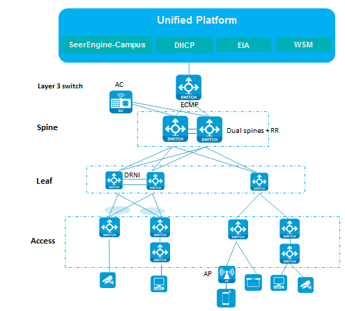
Configure DRNI
For the dual spine configuration, see 0"Configure dual spine uplink". Dual spine devices are manually incorporated by the controller. After the controller incorporates the leaf devices, perform the DRNI configuration. For the controller’s incorporation of spine or leaf devices, see "0AD-Campus configuration." This section describes only the DRNI-specific configuration after leaf device incorporation by the controller.
|
|
IMPORTANT: · For a fabric enabled with DRNI, you need to bind VLAN 4094 address pool to the fabric to facilitate verification for the automatically assigned DRNI virtual IP address. · BGP peers need to be established for dual spine and leaf devices. For detailed configuration, see "Manually incorporate a device." · Keepalive links and IPL links support the use of interfaces at different rates. You need to ensure that the IPL link rates are consistent. · Do not deploy multiple DR systems at the same time. Make sure each DR system is deployed before deploying the next one. · For leaf DRNI networking, access stacking, and BFD MAD detection on access devices, disable BFD MAD VLAN on the uplink interfaces of the access devices. · For leaf DRNI networking, make sure the DRNI environment is established before the user goes online for correct forwarding of service traffic. · To add more IPP or DR interfaces, modify the IPP or DR interface, and then add the corresponding physical interfaces. |
1. Navigate to Automation > Campus Network > Network Devices page, and click IP Address Pools in the upper right corner.
2. On the page for adding an IP address pool, set DRNI as the IP address pool type.
3. DRNI IP address pool is used to configure DRNI addresses. Each DRNI aggregation group needs to be assigned three addresses:
¡ IP address of LoopBack 2 (two devices have the same LoopBack 2 address): Specify the IP address for evpn drni group of DRNI.
¡ IP address of VLAN-interface 2 (each device has an IP address): Used to synchronize underlay routes between the two DR devices.
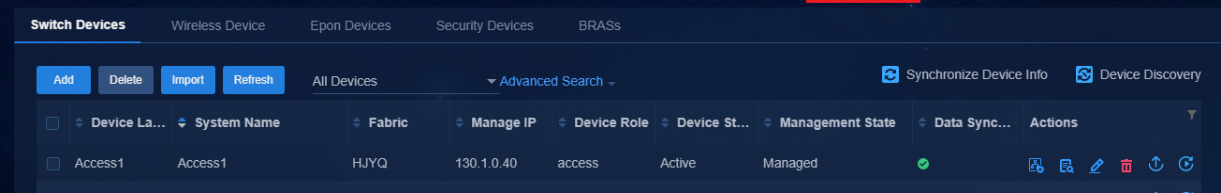
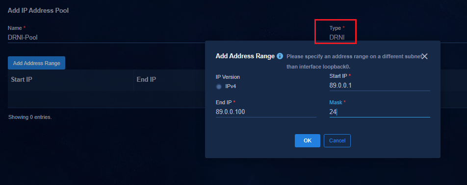
4. Navigate to Automation > Campus
Network > Network Devices page, and click the DRNI link in the
upper right corner. Click the DRNI Parameters tab and click ![]() to
open the page for modifying DRNI parameters.
to
open the page for modifying DRNI parameters.
¡ DRNI State: Select Yes.
¡ DRNI Address Pool: Select the created DRNI address pool.
¡ DRNI Authentication Mode: Select Distributed.

5. Navigate to Automation > Campus Network > Network Devices page, and click the DRNI link in the upper right corner. Click Add to open the page for adding the cross-device aggregation group.
Configure the following parameters:
¡ Name: Enter the name with no limitation.
¡ Fabric: Select HJYQ for enabling DRNI.
¡ Device A Label/Device B Label: Select the two devices that form DRNI.
¡ M-LAG Virtual IP Allocation Method: By default, the IP address is automatically assigned from the device management address pool. To select Manual, make sure the virtual IP address is in the same network segment as the device management address and avoid address conflict.
If the fabric is not configured with an automation template and Auto is selected, configure an address pool in the automation template on the Automation > Campus Network > Fabrics page. Set the VLAN 4094 address pool to be on the same network segment as VXLAN 4094. Otherwise, the system displays a message as follows. If the automation template is already configured, you do not need to configure it again.
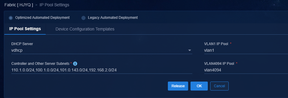
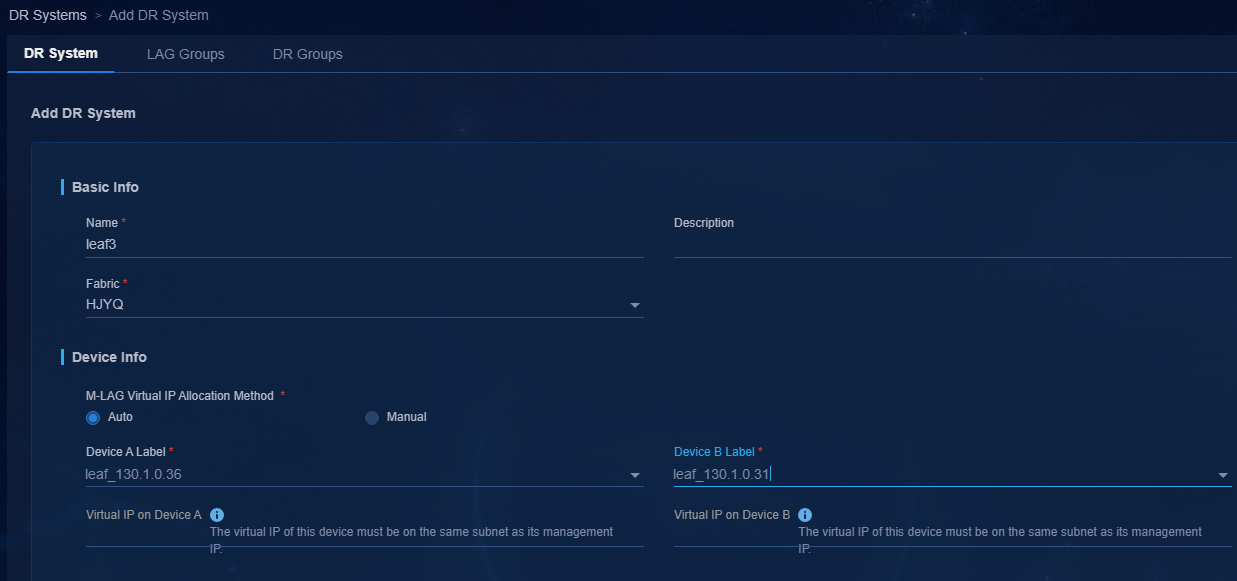
6. After the configuration is completed, the controller automatically generates the DRNI IPP link. On the DR Systems tab, you can view the automatically configured DRNI virtual IP.
7. The time taken to create the cross-device aggregation group varies by device. Perform the next step when the deployment status is completed. Do not deploy multiple cross-device aggregation groups at the same time.
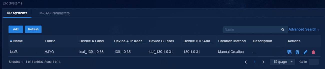
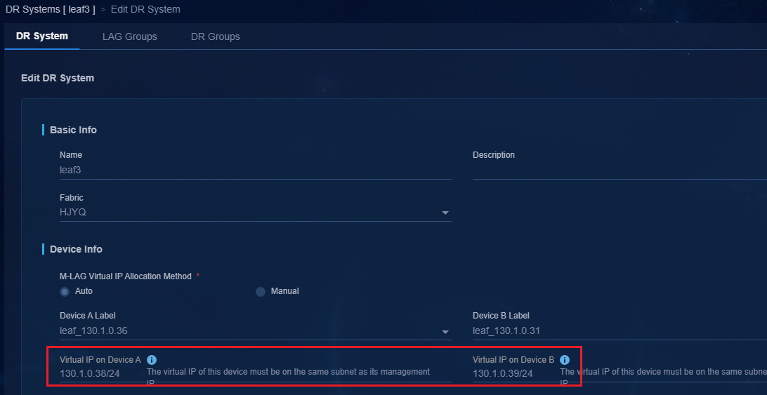
8. Click Return to return to the cross-device aggregation group page. The cross-device aggregation group has been created successfully.
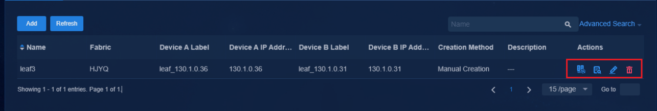
9. Click ![]() , then the device
will automatically create DR aggregation group between leaf and access devices.
, then the device
will automatically create DR aggregation group between leaf and access devices.
10. Before configuring the DR aggregation group, navigate to the Monitor > Topology View > Campus Topology page to view the topology links between leaf and access devices. Make sure the leaf and access devices are activated and the topology is normal.
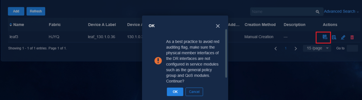
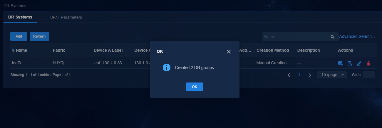
11. After the aggregation group is created,
click ![]() in the Actions column to edit the aggregation group.
in the Actions column to edit the aggregation group.
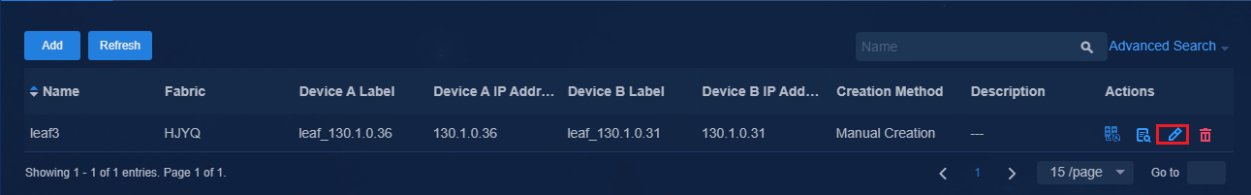
12. Click the LAG Groups tab to view the automatically generated DR aggregation groups in the list.
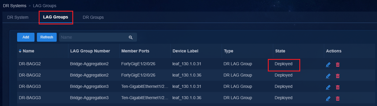
13. You can configure DR aggregation group by
clicking ![]() .
.
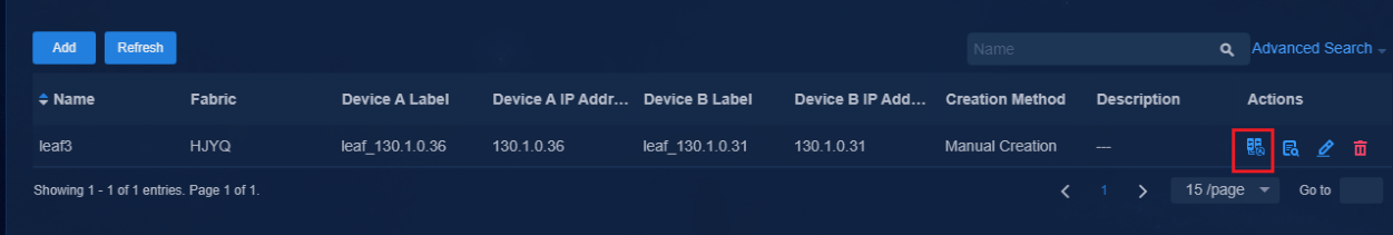

14. After completing the configuration, click ![]() in the
Actions column. You can view the added DR aggregate interface.
in the
Actions column. You can view the added DR aggregate interface.
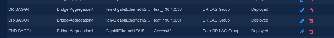
15. After completing the configuration, you can view the DRNI status of the device.
<Leaf-S105A>dis drni summary
Flags: A -- Aggregate interface down, B -- No peer DR interface configured
C -- Configuration consistency check failed
IPP: BAGG1
IPP state (cause): UP
Keepalive link state (cause): UP
DR interface information
DR interface DR group Local state (cause) Peer state Remaining down time(s)
BAGG2 1 UP UP -
BAGG3 2 UP UP -
BAGG4 3 UP UP -
<Leaf-S105A>
Configure DRNI for dual spine devices (manual)
In the current software version, the controller supports only the DRNI configuration for leaf devices. The DRNI configuration of spine devices requires manual configuration as described in this section.
In the current software version, the controller supports only manual DRNI configuration for spine devices. This section describes only the settings specific to the dual spine DRNI networking. For other settings, see 0"Manually incorporate a device."
Configure the Layer 3 switch
Create VLAN 10 and VLAN 11.
#
vlan 10 to 11
#
Create VLAN interfaces for VLAN 10 and VLAN 11.
#
interface Vlan-interface10
ip address 10.0.0.1 255.255.255.0
#
interface Vlan-interface11
ip address 11.0.0.1 255.255.255.0
#
Configure the interface connected to Spine1 to allow VLAN 10 to pass through.
#
interface Ten-GigabitEthernet1/0/25
port link-mode bridge
port link-type trunk
port trunk permit vlan 10 //Configure permitted VLANs based on the actual networking. If the configuration is not required, execute the undo permit vlan1 command.
#
Configure the interface connected to Spine2 to allow VLAN 11 to pass through.
#
interface Ten-GigabitEthernet1/0/26
port link-mode bridge
port link-type trunk
port trunk permit vlan 11 //Configure permitted VLANs based on the actual networking. If the configuration is not required, execute the undo permit vlan1 command.
#
Configure Track.
#
track 1 interface Ten-GigabitEthernet1/0/25 physical
track 2 interface Ten-GigabitEthernet1/0/26 physical
#
Configure two default routes. The next hops are the IP addresses of Spine1 and Spine2.
#
ip route-static 0.0.0.0 0 10.0.0.11 track 1
ip route-static 0.0.0.0 0 11.0.0.11 track 2
#
Connection between Spine1 and L3 switch
Create VLAN 10 and VLAN 11.
#
vlan 10 to 11
#
Create VLAN interfaces for VLAN 10 and VLAN 11 and bind them to vpn-default.
#
interface Vlan-interface10
ip binding vpn-instance vpn-default
ip address 10.0.0.11 255.255.255.0
#
#
interface Vlan-interface11
ip binding vpn-instance vpn-default
ip address 11.0.0.11 255.255.255.0
#
Configure the interface connected to L3 Switch to allow VLAN 10 to pass through.
#
interface Ten-GigabitEthernet2/0/31
port link-mode bridge
port link-type trunk
port trunk permit vlan 10 //Configure permitted VLANs based on the actual networking. If the configuration is not required, execute the undo permit vlan1 command.
#
Configure NQA and Track. Configure static routes to the server cluster, with gateway IP addresses of VLAN 10 and VLAN 11 on the L3 switch as the next hops, and associate the static routes with Track.
#
nqa entry admin server1
type icmp-echo
destination ip 10.0.0.1
frequency 100
reaction 3 checked-element probe-fail threshold-type consecutive 3 action-type trigger-only
vpn-instance vpn-default
#
nqa entry admin server2
type icmp-echo
destination ip 11.0.0.1
frequency 100
reaction 4 checked-element probe-fail threshold-type consecutive 3 action-type trigger-only
vpn-instance vpn-default
#
nqa schedule admin server1 start-time now lifetime forever
nqa schedule admin server2 start-time now lifetime forever
#
track 3 nqa entry admin server1 reaction 3
track 4 nqa entry admin server2 reaction 4
#
#
ip route-static vpn-instance vpn-default 100.1.0.0 24 10.0.0.1 track 3
ip route-static vpn-instance vpn-default 100.1.0.0 24 11.0.0.1 track 4 preference 61
ip route-static vpn-instance vpn-default 110.1.0.0 24 10.0.0.1 track 3
ip route-static vpn-instance vpn-default 110.1.0.0 24 11.0.0.1 track 4 preference 61
#
Connection between Spine2 and L3 switch
Create VLAN 10 and VLAN 11.
#
vlan 10 to 11
#
Create VLAN interfaces for VLAN 10 and VLAN 11 and bind them to vpn-default.
#
interface Vlan-interface10
ip binding vpn-instance vpn-default
ip address 10.0.0.12 255.255.255.0
#
#
interface Vlan-interface11
ip binding vpn-instance vpn-default
ip address 11.0.0.12 255.255.255.0
#
Configure the interface connected to L3 Switch to allow VLAN 11 to pass through.
#
interface Ten-GigabitEthernet2/0/31
port link-mode bridge
port link-type trunk
port trunk permit vlan 11 //Configure permitted VLANs based on the actual networking. If the configuration is not required, execute the undo permit vlan1 command.
#
Configure NQA and Track. Configure static routes to the server cluster, with gateway IP addresses of VLAN 10 and VLAN 11 on the L3 switch as the next hops, and associate the static routes with Track.
#
nqa entry admin server1
type icmp-echo
destination ip 10.0.0.1
frequency 100
reaction 3 checked-element probe-fail threshold-type consecutive 3 action-type trigger-only
vpn-instance vpn-default
#
nqa entry admin server2
type icmp-echo
destination ip 11.0.0.1
frequency 100
reaction 4 checked-element probe-fail threshold-type consecutive 3 action-type trigger-only
vpn-instance vpn-default
#
nqa schedule admin server1 start-time now lifetime forever
nqa schedule admin server2 start-time now lifetime forever
#
#
track 3 nqa entry admin server1 reaction 3
track 4 nqa entry admin server2 reaction 4
#
ip route-static vpn-instance vpn-default 100.1.0.0 24 10.0.0.1 track 3 preference 61
ip route-static vpn-instance vpn-default 100.1.0.0 24 11.0.0.1 track 4
ip route-static vpn-instance vpn-default 110.1.0.0 24 10.0.0.1 track 3 preference 61
ip route-static vpn-instance vpn-default 110.1.0.0 24 11.0.0.1 track 4
#
Configure DRNI for Spine1
Configure OSPF FRR.
#
ospf 1 router-id 200.1.1.254 //Specify a unique router ID across the network. Borrow the IP address of LoopBack 0.
non-stop-routing
fast-reroute lfa
area 0.0.0.0
#
Configure LoopBack 2. Spine1 and Spine2 must have the same IP address.
#
interface LoopBack2
ip address 99.99.0.10 255,255,255,255
ospf 1 area 0.0.0.0
#
Create VLAN 2. Configure VLAN-interface 2. Spine1 and Spine2 use different IP addresses. VLAN 2 is used to synchronize underlay routes between the two DR devices.
#
Vlan 2
#
interface Vlan-interface2
ip address 99.99.0.11 255.255.255.0
ospf network-type p2p
ospf 1 area 0.0.0.0
#
Configure the MAC address for VSI-interface 4094 and the same MAC address for Spine1 and Spine2.
#
interface Vsi-interface4094
ip binding vpn-instance vpn-default
ip address 120.0.0.1 255.255.255.0
mac-address 0001-0001-0005
local-proxy-arp enable
#
Configure loop detection to prevent loops in VXLAN 4094.
#
vsi vxlan4094
loopback-detection action block
loopback-detection enable vlan 4094
#
Configure EVPN distributed aggregation mode. Spine1 and Spine2 have the same configuration.
#
l2vpn drni peer-link ac-match-rule vxlan-mapping
evpn drni group 99.99.0.10 //Specify the VTEP address as the IP address of loopback 2 interface. The device will be reactivated.
evpn global-mac 0001-0001-0004//Spine1 and Spine2 use the same MAC address.
#
#
vxlan default-decapsulation source interface LoopBack0
#
Configure the MAC address advertised by BGP as drni group-address.
#
bgp 1
address-family l2vpn evpn
nexthop evpn-drni group-address
#
Configure keepalive interface. (Layer 3 interface. Logical and physical interfaces are supported.)
#
ip vpn-instance DRNI_KeepAlive //Configure a dedicated VPN instance for keepalive.
#
#
interface FortyGigE3/0/33
port link-mode route
ip binding vpn-instance DRNI_KeepAlive //Bind a VPN instance.
ip address 192.168.0.1 255.255.255.252 //Configure the subnet mask as 30 bits. Spine1 and Spine2 use different IP addresses.
#
Configure local and remote IP addresses for keepalive.
#
drni keepalive ip destination 192.168.0.2 source 192.168.0.1 vpn-instance DRNI_KeepAlive
#
Configure the DR system parameters
Configure devices in the DR group with the same system MAC address and different system numbers.
#
drni restore-delay 180
drni system-mac 542b-de08-8200
drni system-number 1
drni system-priority 10
#
Configure the IPP (Layer 2 aggregate interface).
#
interface Bridge-Aggregation1
port link-type trunk
port trunk permit vlan all
port trunk pvid vlan 4094 //PVID 4094 is required.
link-aggregation mode dynamic
port drni intra-portal-port 1 //Configure IPP.
undo mac-address static source-check enable //Disable the MAC address source check.
#
#
interface Ten-GigabitEthernet2/0/1
port link-mode bridge
port link-type trunk
port trunk permit vlan all
port trunk pvid vlan 4094
port link-aggregation group 1
#
#
interface Ten-GigabitEthernet2/0/15
port link-mode bridge
port link-type trunk
port trunk permit vlan all
port trunk pvid vlan 4094
port link-aggregation group 1
#
Configure DRNI MAD:
#
drni mad default-action none
#
track 1024 drni-mad-status
#
#
interface LoopBack2
ip address 99.99.0.10 255,255,255,255
ospf 1 area 0.0.0.0
ospf track 1024 adjust-cost max
#
The aging time for the MAC address must be no less than 20 minutes.
#
mac-address timer aging 1560
#
Disable the MAC address source check of the interface connecting Spine1 to the leaf device.
#
interface Ten-GigabitEthernet1/2/0/47
port link-mode bridge
port link-type trunk
port trunk permit vlan 1 3497
lldp source-mac vlan 3497
lldp management-address arp-learning vlan 3497
lldp tlv-enable basic-tlv management-address-tlv interface LoopBack0
undo mac-address static source-check enable
#
Configure the automatic recovery time upon device restart.
Configure the timer to be greater than the device restart time to avoid role preemption between DR devices.
drni auto-recovery reload-delay delay-value 600
#
Configure DRNI for Spine2
Configure OSPF FRR.
#
ospf 1 router-id 200.1.1.253 //Specify a unique router ID across the network. Borrow the IP address of LoopBack 0.
non-stop-routing
fast-reroute lfa
area 0.0.0.0
#
Configure LoopBack 2. Spine1 and Spine2 must have the same IP address.
#
interface LoopBack2
ip address 99.99.0.10 255,255,255,255
ospf 1 area 0.0.0.0
#
Create VLAN 2. Configure VLAN-interface 2. Spine1 and Spine2 use different IP addresses.
#
Vlan 2
#
interface Vlan-interface2
ip address 99.99.0.12 2 55.255.255.0
ospf network-type p2p
ospf 1 area 0.0.0.0
#
Configure the MAC address for VSI-interface 4094. Spine1 and Spine2 use the same MAC address.
#
interface Vsi-interface4094
ip binding vpn-instance vpn-default
ip address 120.0.0.2 255.255.255.0
mac-address 0001-0001-0005
local-proxy-arp enable
#
Configure loop detection to prevent loops in VXLAN 4094.
#
vsi vxlan4094
loopback-detection action block
loopback-detection enable vlan 4094
#
Configure EVPN distributed aggregation mode. Spine1 and Spine2 have the same configuration.
#
l2vpn drni peer-link ac-match-rule vxlan-mapping
evpn drni group 99.99.0.10 //Specify the VTEP address as the IP address of loopback 2 interface. The device will be reactivated.
evpn global-mac 0001-0001-0004 //Spine1 and Spine2 use the same MAC address.
#
#
vxlan default-decapsulation source interface LoopBack0
#
Configure the MAC address advertised by BGP as drni group-address.
#
bgp 1
address-family l2vpn evpn
nexthop evpn-drni group-address
#
Configure the keepalive interface. (Layer 3 interface. Logical and physical interfaces are available.)
#
ip vpn-instance DRNI_KeepAlive //Configure a dedicated VPN instance for keepalive.
#
#
interface FortyGigE3/0/33
port link-mode route
ip binding vpn-instance DRNI_KeepAlive // Bind a VPN instance.
ip address 192.168.0.2 255.255.255.252 // Configure the subnet mask as 30 bits. Spine1 and Spine2 use different IP addresses.
#
Configure local and remote IP addresses for keepalive.
#
drni keepalive ip destination 192.168.0.1 source 192.168.0.2 vpn-instance DRNI_KeepAlive
#
Configure the DR system parameters. Set the same system MAC address and different system numbers for the devices in the DR group.
#
drni restore-delay 180
drni system-mac 542b-de08-8200
drni system-number 2
drni system-priority 10
#
Configure the IPP (Layer 2 aggregate interface).
#
interface Bridge-Aggregation1
description SDN_LAGG
port link-type trunk
port trunk permit vlan all
port trunk pvid vlan 4094 //PVID 4094 is required.
link-aggregation mode dynamic
port drni intra-portal-port 1 //Configure IPP.
undo mac-address static source-check enable //Disable the MAC address source check.
#
#
interface Ten-GigabitEthernet3/0/15
port link-mode bridge
port link-type trunk
undo port trunk permit vlan 1
port trunk permit vlan 2 to 4094
port trunk pvid vlan 4094
port link-aggregation group 1
#
#
interface Ten-GigabitEthernet3/0/22
port link-mode bridge
port link-type trunk
undo port trunk permit vlan 1
port trunk permit vlan 2 to 4094
port trunk pvid vlan 4094
port link-aggregation group 1
#
#
Configure DRNI MAD:
#
drni mad default-action none
#
track 1024 drni-mad-status
#
#
interface LoopBack2
ip address 99.99.0.10 255,255,255,255
ospf 1 area 0.0.0.0
ospf track 1024 adjust-cost max
#
The aging time for the MAC address must be no less than 20 minutes.
#
mac-address timer aging 1560
#
Disable the MAC address source check of the interface connecting Spine1 to the leaf device.
#
interface Ten-GigabitEthernet1/2/0/47
port link-mode bridge
port link-type trunk
port trunk permit vlan 1 3498
lldp source-mac vlan 3498
lldp management-address arp-learning vlan 3498
lldp tlv-enable basic-tlv management-address-tlv interface LoopBack0
undo mac-address static source-check enable
#
Configure the automatic recovery time upon device restart.
Configure this timer to be greater than the device restart time to avoid role preemption between DR devices.
drni auto-recovery reload-delay delay-value 600
#
Configure IP-SGT
IP-SGT is an industry-leading solution. The device obtains the IP-SGT role from the AAA server through subscription. Users can obtain the same permissions upon coming online in different locations. The IP-SGT configuration includes two parts: the device subscripts IP-SGT information from the EIA and the EIA pushes the information to the device.
IP-SGT features less networking requirements and improves adaptability of the uniform policy enforcement solution in various scenarios.
· Authentication points and uniform policy enforcement points can be separated.
· Uniform policy enforcement is supported across multiple isolated domains in IP-Transit scenarios.
· Decouples security groups from VLANs. Wireless user IP roles (SGTs) are obtained through subscriptions.
|
|
NOTE: IP-SGT requires the device to establish a WebSocket channel with the controller through VLAN 1. When configuring IP-SGT, make sure the device can communicate with the controller through VLAN 1. |
Campus configuration
1. Navigate to the Automation > Campus
Network > Isolation Domain page and click ![]() to
open the page for editing an isolation domain.
to
open the page for editing an isolation domain.
2. Click Advanced Settings tab and set On for IP-Security Group Tag Subscription.
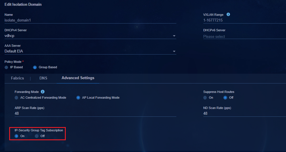
3. After the setting, the controller issues the following command to the device:
#
ipsgt enable //Enable IPSG function.
ipsgt on-demand ip 20.0.0.0 255.255.0.0 vpn-instance Teach //Enable the on-demand deployment function for each network segment.
ipsgt on-demand ip 30.0.0.0 255.255.0.0 vpn-instance Teach
ipsgt on-demand ip 30.1.0.0 255.255.0.0 vpn-instance Teach
#
EIA configuration
1. Navigate to the Automation > Campus Network > User > Service Parameters > Access Parameters > Manage IP-SGT Service Subscriptions page.
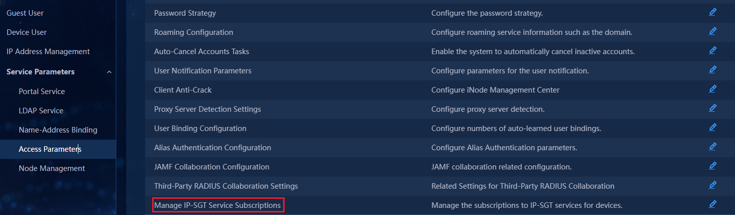
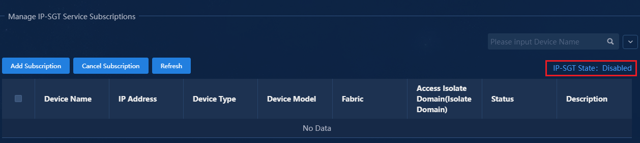
2. Click IP-SGT State, and click OK in the dialog box to enable IP-SGT services.
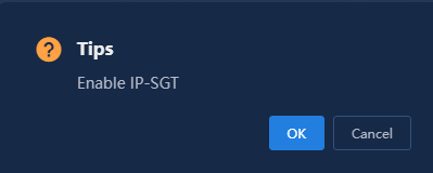
3. Click Add Subscription. The devices in the Add Subscription page are incorporated by the controller.

4. Select the device for subscription and click OK.
5. The controller establishes the Websocket connection with the device. After the connection, the connection status becomes UP.
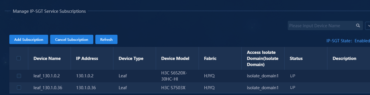
//You can view the status by using the following command:
[Leaf-S105A]dis cloud-management state
Cloud connection state : Established
Device state : Request_success
Cloud server address : 100.1.0.100
Cloud server domain name : 100.1.0.100
Cloud server port : 443
Connected at : Mon Jan 24 07:47:24 2022
Duration : 00d 03h 38m 17s
Process state : Message received
Failure reason : N/A
[Leaf-S105A]
//View subscription information when end users come online by using the following command:
[Leaf-S105A]dis ipsgt map
Total IPv4 IP-SGT entries: 2
Microsegment ID: 3503
IPv4 address Vpn instance
23.3.0.3 vpn1
23.3.0.4 vpn1
Total IPv6 IP-SGT entries: 0
[Leaf-S105A]
O&M monitoring
For more information, see AD-Campus 6.2 Maintenance Guide.
