- Released At: 22-12-2022
- Page Views:
- Downloads:
- Table of Contents
- Related Documents
-
|
|
|
H3C SR8800-X Router Series |
|
MPU Datasheet |
|
|
|
|
Copyright © 2015 to 2022 New H3C Technologies Co., Ltd. All rights reserved.
No part of this manual may be reproduced or transmitted in any form or by any means without prior written consent of New H3C Technologies Co., Ltd.
Except for the trademarks of New H3C Technologies Co., Ltd., any trademarks that may be mentioned in this document are the property of their respective owners.
The information in this document is subject to change without notice.
Contents
High performance routing engine
Flexible configuration and compatibility
SMB coaxial clock input/output port
Overview
An MPU provides the following functions:
· Route calculation and forwarding table maintenance.
· System configuration and monitoring. It can monitor, upgrade, and reset the service modules.
· Active/standby switchover.
The following MPUs are available for the SR8800-X routers.
Table 1 MPUs available for the SR8800-X routers
|
Card model |
Description |
|
SR05SRP1L1 |
H3C SR8800-X, management and route process unit (1L1) |
|
SR05SRP1L3 |
H3C SR8800-X, management and route process unit (1L3) |
|
SR05SRP1P3 |
H3C SR8800-X main processing unit (1P3) |
|
CSR05SRP1P1 |
H3C SR8800-X main processing unit (1P1) |
|
CSR05SRP1P3-G |
H3C SR8800-X main processing unit (1P3-G) |
|
CSR05SRP1R3 |
H3C SR8800-X main processing unit (1R3) |
|
SR07SRPUA1 |
H3C SR8800-X-S management and route processing unit (UA1) |
|
SR07SRPUB1 |
H3C SR8800-X-S management and route processing unit (UB1) |
|
SR07SRPUC1 |
H3C SR8803-X-S management and route processing unit |
|
SR07SRPUD3 |
H3C SR8800-X-S management and route process board (UD3) |
|
SR07MPUA1 |
H3C SR8802-X-S management and route processing unit |
|
SR07MPUA3 |
H3C SR8802-X-S management and route process board (UA3) |
Key features
High performance routing engine
The MPUs employ high performance multi-CPUs to provide powerful routing processing capability and powerful message processing capability for protocol messages and control messages.
Flexible configuration and compatibility
You can install one or two MPUs for the router. When two MPUs are installed, the router supports active/standby MPU switchover.
Hot swapping
You can install an MPU when the router is operating. When two MPUs are installed, you can remove one of them, without interrupting the service module services. The management system performs real-time monitoring on the MPUs and automatically adapts to the changed configuration upon detection of the change, ensuring service continuity.
10-GE MCC ports
10-GE MCC ports connect IRF member routers. The SR07SRPUA1 provides four 10-GE MCC ports and the SR07SRPUB1 and SR07SRPUD3 each provide two 10-GE MCC ports.
Specifications
|
|
CAUTION: For the standby MPU to start up correctly, make sure the active and standby MPUs are the same model. |
The figures in this section are for illustration only.
SR05SRP1L1
Figure 1 SR05SRP1L1
Front panel
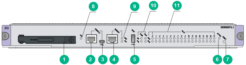
Figure 2 SR05SRP1L1 front panel
|
(1) CF card |
(2) Console port |
|
(3) USB console port |
(4) 10/100/1000BASE-T network management port |
|
(5) USB 2.0 port |
(6) MPU active/standby status LED (see Table 13) |
|
(7) Reset button |
(8) CF card LED (see Table 2) |
|
(9) Network management port LEDs (see Table 3) |
(10) Fan tray status LEDs (see Table 6) |
|
(11) Module status LEDs (see Table 10) |
|
Technical specifications
|
Item |
Specifications |
|
SDRAM (DDR3) |
8 GB |
|
Dimensions (H × W × D) |
40 × 399 × 352 mm (1.57 × 15.71 × 13.86 in) |
|
Net weight |
3.05 kg (6.72 lb) |
|
Power consumption |
46 W to 53 W |
|
Ports |
· 1 × console port · 1 × USB console port · 1 × network management port · 1 × USB 2.0 port · 1 × CF card slot For the port specifications, see "Ports." |
|
System software version |
7133 or later |
SR05SRP1L3
Figure 3 SR05SRP1L3
Front panel
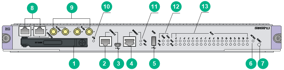
Figure 4 SR05SRP1L3 front panel
|
(1) CF card |
(2) Console port |
|
(3) USB console port |
(4) 10/100/1000BASE-T network management port |
|
(5) USB 2.0 port |
(6) MPU active/standby status LED (see Table 13) |
|
(7) Reset button |
(8) High-precision time synchronization ports |
|
(9) SMB coaxial clock ports |
(10) CF card LED (see Table 2) |
|
(11) Network management port LEDs (see Table 3) |
(12) Fan tray status LEDs (see Table 6) |
|
(13) Module status LEDs (see Table 10) |
|
|
|
NOTE: By default, both high-precision time synchronization ports are input ports. Only port 1 is available for input when both ports are input ports. |
Technical specifications
|
Item |
Specifications |
|
SDRAM (DDR3) |
8 GB or 16 GB |
|
Dimensions (H × W × D) |
40 × 399 × 352 mm (1.57 × 15.71 × 13.86 in) |
|
Net weight |
3.18 kg (7.01 lb) |
|
Power consumption |
50 W to 53 W |
|
Ports |
· 1 × console port · 1 × USB console port · 1 × network management port · 1 × USB 2.0 port · 1 × CF card slot · 2 × SMB coaxial clock output ports · 2 × SMB coaxial clock input ports · 2 × high-precision time synchronization ports For the port specifications, see "Ports." |
|
System software version |
7133 or later |
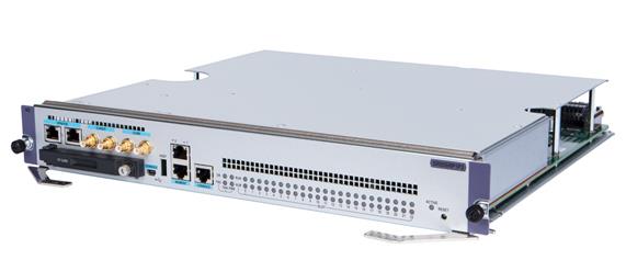
SR05SRP1P3
Figure 5 SR05SRP1P3
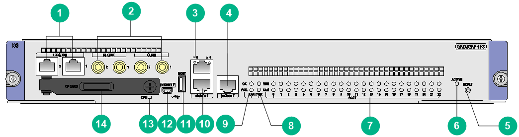
Front panel
Figure 6 SR05SRP1P3 front panel
|
(1) High-precision time synchronization ports |
(2) SMB coaxial clock ports |
|
(3) Network management port LED (see Table 4) |
(4) Console port |
|
(5) Reset button |
(6) MPU active/standby status LED (see Table 13) |
|
(7) Module status LEDs (see Table 10) |
(8) Power supply status LEDs (see Table 8) |
|
(9) Fan tray status LEDs (see Table 6) |
(10) 10/100/1000BASE-T network management port |
|
(11) USB 2.0 port |
(12) USB console port |
|
(13) CF card LED (see Table 2) |
(14) CF card |
|
|
NOTE: By default, both high-precision time synchronization ports are input ports. Only port 1 is available for input when both ports are input ports. |
Technical specifications
|
Item |
Specifications |
|
SDRAM (DDR3) |
16 GB |
|
Built-in SD card |
4 GB |
|
Dimensions (H × W × D) |
52.2 × 399 × 352 mm (2.06 × 15.71 × 13.86 in) |
|
Net weight |
4.40 kg (9.70 lb) |
|
Power consumption |
58 W to 64 W |
|
Ports |
· 1 × console port · 1 × USB console port · 2 × network management ports · 1 × USB 2.0 port · 1 × CF card slot · 2 × SMB coaxial clock output ports · 2 × SMB coaxial clock input ports · 2 × high-precision time synchronization ports For the port specifications, see "Ports." |
|
System software version |
7606 or later |
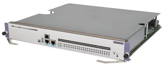
CSR05SRP1P1
Figure 7 CSR05SRP1P1
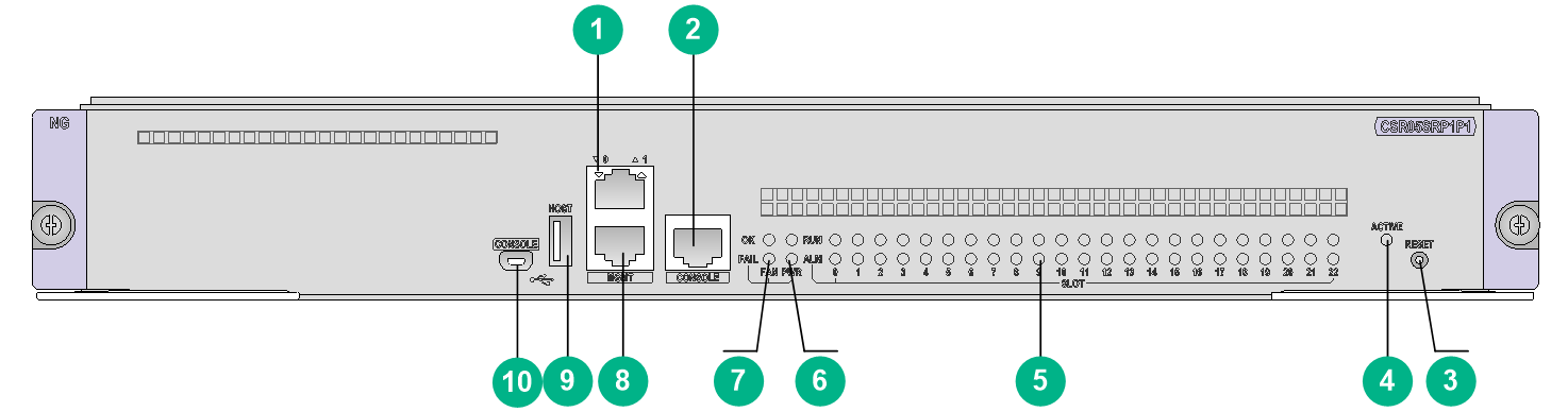
Front panel
Figure 8 CSR05SRP1P1 front panel
|
(1) Management Ethernet port LED |
(2) Console port |
|
(3) Reset button |
(4) MPU active/standby status LED (see Table 13) |
|
(5) Module status LEDs (see Table 10) |
(6) Power supply status LEDs (see Table 8) |
|
(7) Fan tray status LEDs (see Table 6) |
(8) 10/100/1000BASE-T management Ethernet port |
|
(9) USB 2.0 port |
(10) USB console port |
Technical specifications
|
Item |
Specifications |
|
|
SDRAM (DDR3) |
8 GB |
|
|
Dimensions (H × W × D) |
52.2 × 399 × 352 mm (2.06 × 15.71 × 13.86 in) |
|
|
Net weight |
4.2 kg (9.26 lb) |
|
|
Power consumption |
58 W to 64 W |
|
|
Ports |
· 1 × console port · 1 × USB console port · 2 × management Ethernet ports · 1 × USB 2.0 port For the port specifications, see "Ports." |
|
|
Applicable system software versions |
8158P18 or later |
|
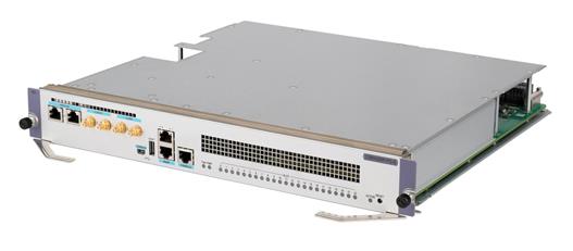
CSR05SRP1P3-G
Figure 9 CSR05SRP1P3-G
Front panel
Figure 10 CSR05SRP1P3-G front panel
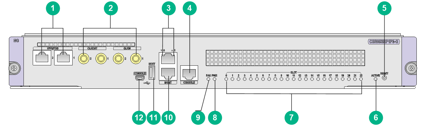
|
(1) High-precision time synchronization ports |
(2) SMB coaxial clock ports |
|
(3) Management Ethernet port LED (see Table 4) |
(4) Console port |
|
(5) Reset button |
(6) MPU active/standby status LED (see Table 13) |
|
(7) Module status LEDs (see Table 10) |
(8) Power status LEDs (see Table 9) |
|
(9) Fan tray status LEDs (see Table 7) |
(10) 1000BASE-T management Ethernet port |
|
(11) USB 2.0 port |
(12) USB console port |
|
|
NOTE: By default, both high-precision time synchronization ports are input ports. Only port 1 takes effect when both ports are input ports. |
Technical specifications
|
Item |
Specifications |
|
|
SDRAM (DDR4) |
2*8 GB |
|
|
Dimensions (H × W × D) |
52.2 × 399 × 352 mm (2.06 × 15.71 × 13.86 in) |
|
|
Net weight |
4.50 kg (9.92 lb) |
|
|
Power consumption |
50 W to 80 W |
|
|
Ports |
· 1 × RJ-45 console port · 1 × mini USB console port · 2 × RJ-45 management Ethernet ports · 1 × USB 2.0 port · 2 × SMB coaxial clock output ports · 2 × SMB coaxial clock input ports · 2 × RJ-45 high-precision time synchronization ports For the port specifications, see "Ports." |
|
|
Applicable system software versions |
8308 or later |
|
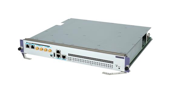
CSR05SRP1R3
Figure 11 CSR05SRP1R3
Front panel
Figure 12 CSR05SRP1R3 front panel
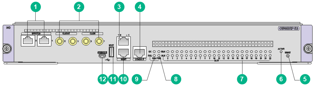
|
(1) High-precision time synchronization ports |
(2) SMB coaxial clock ports |
|
(3) Management Ethernet port LED (see Table 4) |
(4) Console port |
|
(5) Reset button |
(6) MPU active/standby status LED (see Table 13) |
|
(7) Module status LEDs (see Table 10) |
(8) Power supply status LEDs (see Table 8) |
|
(9) Fan tray status LEDs (see Table 6) |
(10) 1000BASE-T management Ethernet port |
|
(11) USB 2.0 port |
(12) USB console port |
|
|
NOTE: By default, both high-precision time synchronization ports are input ports. Only port 1 is available for input when both ports are input ports. |
Technical specifications
|
Item |
Specifications |
|
|
SDRAM (DDR4) |
2 × 16 GB |
|
|
Dimensions (H × W × D) |
52.2 × 399 × 352 mm (2.06 × 15.71 × 13.86 in) |
|
|
Net weight |
3.70 kg (8.16 lb) |
|
|
Power consumption |
86 W to 130 W |
|
|
Ports |
· 1 × console port · 1 × USB console port · 2 × management Ethernet ports (port 1 not supported) · 1 × USB 2.0 port · 2 × SMB coaxial clock output ports · 2 × SMB coaxial clock input ports · 2 × high-precision time synchronization ports (default: input ports) For the port specifications, see "Ports." |
|
|
Applicable system software versions |
8303 or later |
|
SR07SRPUA1
Figure 13 SR07SRPUA1
Front panel
Figure 14 SR07SRPUA1 front panel
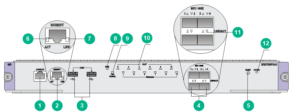
|
(1) Console port |
(2) 10/100/1000BASE-T network management port |
|
(3) USB 2.0 ports |
(4) 10-GE MCC ports |
|
(5) Reset button |
(6) Network management port LED (ACT) (see Table 3) |
|
(7) Network management port LED (LINK) (see Table 3) |
(8) Power supply status LED (see Table 9) |
|
(9) Fan tray status LED (see Table 7) |
(10) Module status LEDs (see Table 11) |
|
(11) 10-GE MCC port LEDs (see Table 5) |
(12) MPU active/standby status LED (see Table 13) |
Technical specifications
|
Item |
Specifications |
|
SDRAM (DDR3) |
4 GB |
|
Dimensions (H × W × D) |
46 × 399 × 352 mm (1.81 × 15.71 × 13.86 in) |
|
Net weight |
4.35 kg (9.59 lb) |
|
Power consumption |
49 W to 75 W |
|
Ports |
· 1 × console port · 1 × network management port · 2 × USB 2.0 ports · 4 × 10-GE MCC ports For the port specifications, see "Ports." |
|
System software version |
7133 or later |
SR07SRPUB1
Figure 15 SR07SRPUB1
Front panel
Figure 16 SR07SRPUB1 front panel
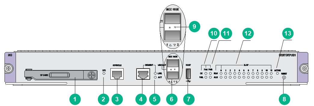
|
(1) CF card |
(2) CF card LED (see Table 2) |
|
(3) Console port |
(4) 10/100/1000BASE-T network management port |
|
(5) Network management port LEDs (see Table 3) |
(6) 10-GE MCC ports |
|
(7) USB 2.0 port |
(8) Reset button |
|
(9) 10-GE MCC port LEDs (see Table 5) |
(10) Fan tray status LEDs (see Table 6) |
|
(11) Power supply status LEDs (see Table 8) |
(12) Module status LEDs (see Table 11) |
|
(13) MPU active/standby status LED (see Table 13) |
|
Technical specifications
|
Item |
Specifications |
|
SDRAM (DDR3) |
4 GB |
|
Dimensions (H × W × D) |
46 × 399 × 352 mm (1.81 × 15.71 × 13.86 in) |
|
Net weight |
3.4 kg (7.50 lb) |
|
Power consumption |
44 W to 60 W |
|
Ports |
· 1 × console port · 1 × network management port · 1 × USB 2.0 port · 2 × 10-GE MCC ports · 1 × CF card slot For the port specifications, see "Ports." |
|
System software version |
7133 or later |
SR07SRPUC1
Figure 17 SR07SRPUC1
Front panel
Figure 18 SR07SRPUC1 front panel
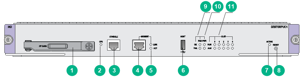
|
(1) CF card |
(2) CF card LED (see Table 2) |
|
(3) Console port |
(4) 10/100/1000BASE-T network management port |
|
(5) Network management port LED (Table 3) |
(6) USB 2.0 port |
|
(7) MPU active/standby status LED (see Table 13) |
(8) Reset button |
|
(9) Fan tray status LEDs (see Table 6) |
(10) Power supply status LEDs (see Table 8) |
|
(11) Module status LEDs (see Table 11) |
|
Technical specifications
|
Item |
Specifications |
|
SDRAM (DDR3) |
4 GB |
|
Dimensions (H × W × D) |
46 × 399 × 352 mm (1.81 × 15.71 × 13.86 in) |
|
Net weight |
3.3 kg (7.28 lb) |
|
Power consumption |
30 W to 45 W |
|
Ports |
· 1 × console port · 1 × network management port · 1 × USB 2.0 port · 1 × CF card slot For the port specifications, see "Ports." |
|
System software version |
7133 or later |
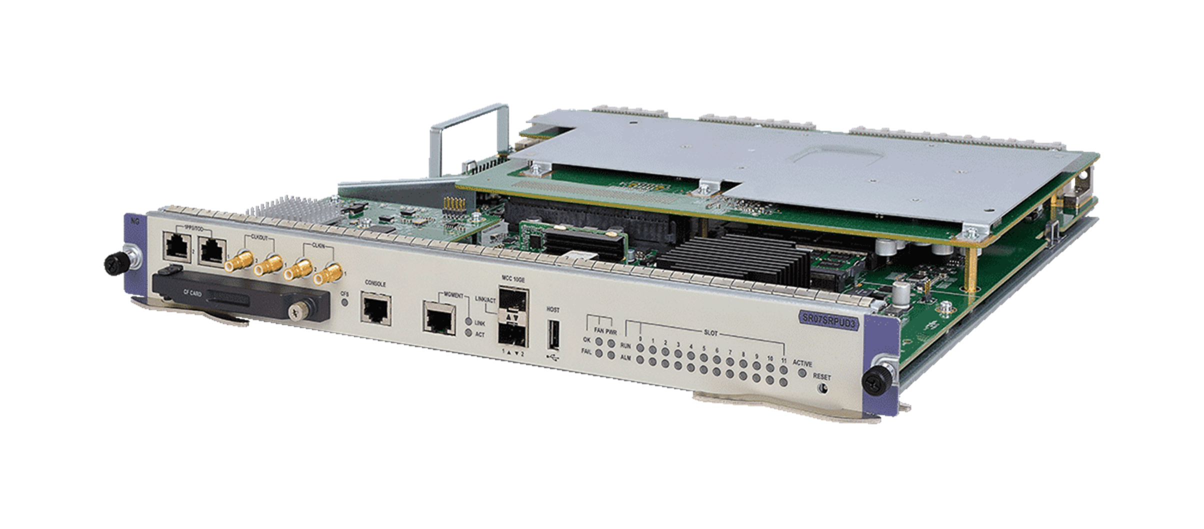
SR07SRPUD3
Figure 19 SR07SRPUD3
Front panel
Figure 20 SR07SRPUD3 front panel
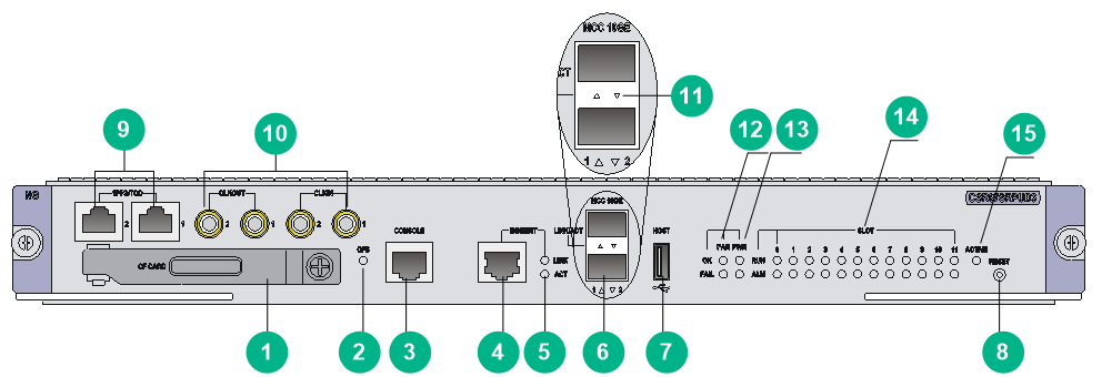
|
(1) CF card |
(2) CF card LED (see Table 2) |
|
(3) Console port |
(4) 10/100/1000BASE-T network management port |
|
(5) Network management port LED (see Table 3) |
(6) 10-GE MCC ports |
|
(7) USB 2.0 port |
(8) Reset button |
|
(9) High-precision time synchronization ports |
(10) SMB coaxial clock ports |
|
(11) 10-GE MCC port LED (see Table 5) |
(12) Fan tray status LEDs (see Table 6) |
|
(13) Power supply status LEDs (see Table 8) |
(14) Module status LEDs (see Table 11) |
|
(15) MPU active/standby status LED (see Table 13) |
|
|
|
NOTE: By default, both high-precision time synchronization ports are input ports. Only port 1 is available for input when both ports are input ports. |
Technical specifications
|
Item |
Specifications |
|
SDRAM (DDR3) |
8 GB |
|
Dimensions (H × W × D) |
46 × 399 × 352 mm (1.81 × 15.71 × 13.86 in) |
|
Net weight |
4.15 kg (9.15 lb) |
|
Power consumption |
80 W to 110 W |
|
Ports |
· 1 × console port · 1 × network management port · 1 × USB 2.0 port · 1 × CF card slot · 2 × SMB coaxial clock output ports · 2 × SMB coaxial clock input ports · 2 × high-precision time synchronization ports · 2 × 10-GE MCC ports For the port specifications, see "Ports." |
|
System software version |
7140P51 or later |
SR07MPUA1
Figure 21 SR07MPUA1
Front panel
Figure 22 SR07MPUA1 front panel
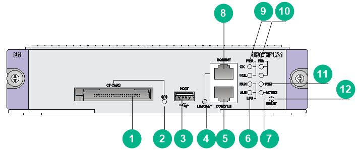
|
(1) CF card |
(2) CF card LED (see Table 2) |
|
(3) USB 2.0 port |
(4) Network management port LED (see Table 4) |
|
(5) Console port |
(6) Service module status LEDs (see Table 12) |
|
(7) MPU active/standby status LED (see Table 13) |
(8) 10/100/1000BASE-T network management port |
|
(9) Power supply status LEDs (see Table 8) |
(10) Fan tray status LEDs (see Table 6) |
|
(11) MPU status LED (see ) |
(12) Reset button |
Technical specifications
|
Item |
Specifications |
|
SDRAM (DDR3) |
4 GB |
|
Dimensions (H × W × D) |
45 × 199 × 352 mm (1.77 × 7.83 × 13.86 in) |
|
Net weight |
1.4 kg (3.09 lb) |
|
Power consumption |
28 W to 35 W |
|
Ports |
· 1 × console port · 1 × network management port · 1 × USB 2.0 port · 1 × CF card slot For the port specifications, see "Ports." |
|
System software version |
7133 or later |
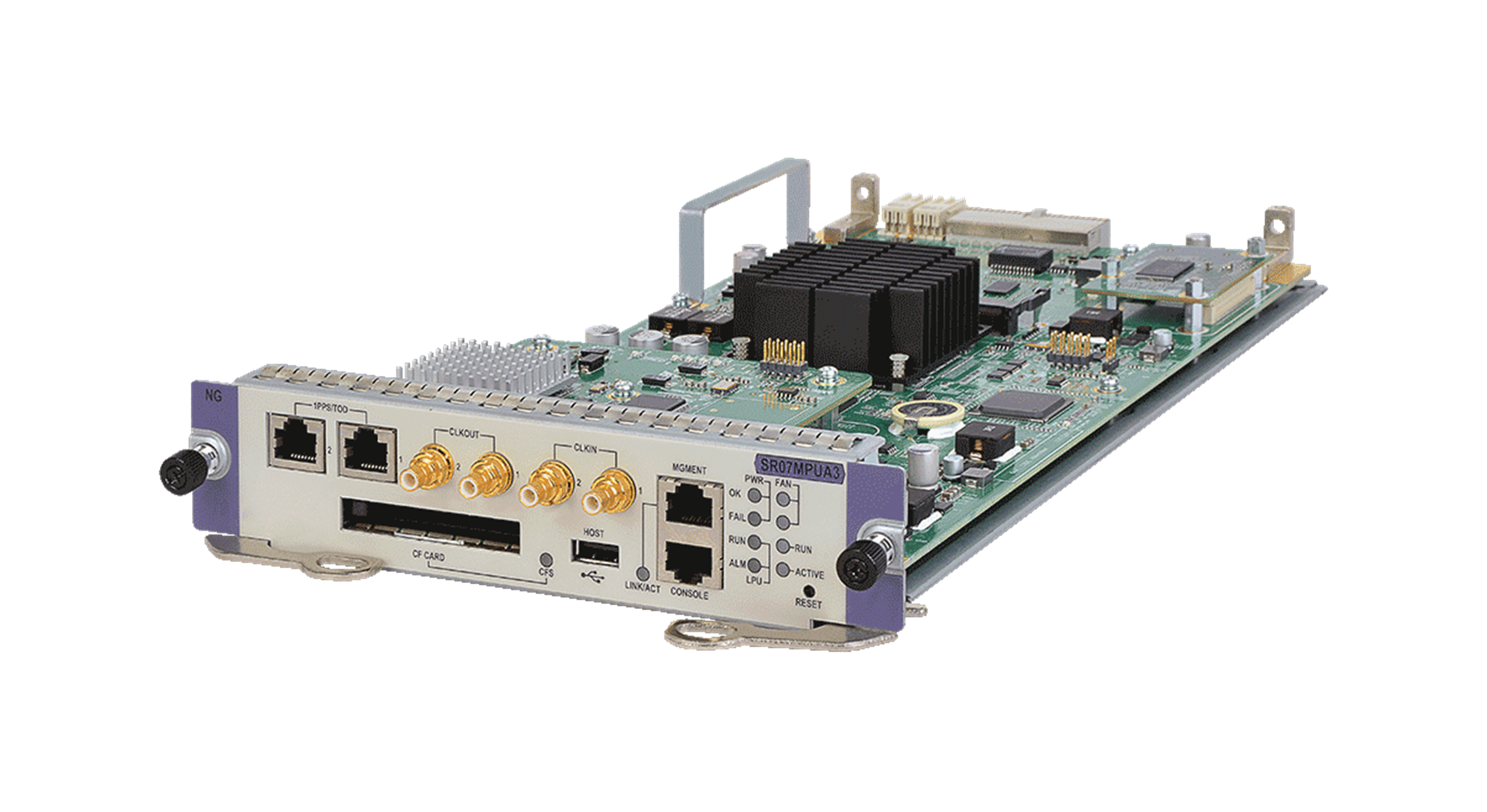
SR07MPUA3
Figure 23 SR07MPUA3
Front panel
Figure 24 SR07MPUA3 front panel
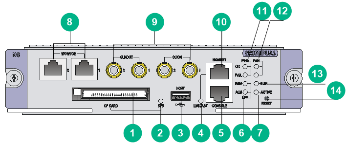
|
(1) CF card |
(2) CF card LED (see Table 2) |
|
(3) USB 2.0 port |
(4) Network management port LED (see Table 4) |
|
(5) Console port |
(6) Service module status LEDs (see Table 12) |
|
(7) MPU active/standby status LED (see Table 13) |
(8) High-precision time synchronization ports |
|
(9) SMB coaxial clock ports |
(10) 10/100/1000BASE-T network management port |
|
(11) Power supply status LEDs (see Table 8) |
(12) Fan tray status LEDs (see Table 6) |
|
(13) MPU card status LED (see ) |
(14) Reset button |
|
|
NOTE: By default, both high-precision time synchronization ports are input ports. Only port 1 is available for input when both ports are input ports. |
Technical specifications
|
Item |
Specifications |
|
SDRAM (DDR3) |
4 GB or 8 GB |
|
Dimensions (H × W × D) |
45 × 199 × 352 mm (1.77 × 7.83 × 13.86 in) |
|
Net weight |
1.55 kg (3.42 lb) |
|
Power consumption |
28 W to 35 W |
|
Ports |
· 1 × console port · 1 × network management port · 1 × USB 2.0 port · 1 × CF card slot · 2 × SMB coaxial clock output ports · 2 × SMB coaxial clock input ports · 2 × high-precision time synchronization ports For the port specifications, see "Ports." |
|
System software version |
7140P51 or later |
LEDs
CF card LED
Table 2 CF card LED description
|
Status |
Description |
|
Steady green |
A CF card is present and idle. Do not hot swap it. |
|
Flashing green |
A CF card is present and the system is reading/writing the CF card. Do not hot swap it. |
|
Off |
No CF card is present or the CF card is offline. You can hot swap the CF card. |
Network management port LEDs
Table 3 Management Ethernet port LED description (1)
|
LINK LED status |
ACT LED status |
Description |
|
Steady green |
Flashing yellow |
The port is receiving or transmitting data. |
|
Steady green |
Off |
A link is present. |
|
Off |
Off |
No link is present. |
Table 4 Management Ethernet port LED description (2)
|
LED |
Status |
Description |
|
LINK/ACT |
Flashing green |
The port is receiving or transmitting data. |
|
Steady green |
A link is present. |
|
|
Off |
No link is present. |
10-GE MCC port LEDs
Table 5 10-GE MCC port LED description
|
LED |
Status |
Description |
|
LINK/ACT |
Flashing green |
A link is present, and the port is receiving or transmitting data. |
|
Steady green |
A link is present. |
|
|
Off |
No link is present. |
Fan tray status LEDs
The SR8804-X and SR8808-X routers each have only one fan tray. FAN0 OK and FAIL LEDs on the MPU indicate the fan tray operating status.
An SR8812-X router has two fan trays. FAN0 OK and FAIL and FAN1 OK and FAIL LEDs on the MPU indicate the operating status of the fan trays, respectively.
Table 6 Fan tray status LED description (1)
|
OK LED status |
FAIL LED status |
Description |
|
Steady green |
Off |
The fan tray is operating correctly. |
|
Off |
Steady red |
An issue has occurred on the fan tray or the fan tray is not present. |
|
Off |
Off |
The router is not powered on. |
Table 7 Fan tray status LED description (2)
|
LED |
Status |
Description |
|
FAN |
Steady green |
The fan tray is operating correctly. |
|
Steady red |
An issue has occurred on the fan tray or the fan tray is not present. |
|
|
Off |
The router is not powered on. |
Power supply status LEDs
Table 8 Power supply status LED description (1)
|
OK LED status |
FAIL LED status |
Description |
|
Steady green |
Off |
All power supplies in the chassis are operating correctly. |
|
Off |
Steady red |
A minimum of one power supply in the chassis does not have power output. Possible reasons include: · Power supply failure. · Power switch turned off. · Power cord connection error. · Outage of the external power source. |
|
Off |
Off |
· No power supply is present in the chassis. · No power supplies in the chassis have power output. Possible reasons include: ¡ Power supply failure. ¡ Power switch turned off. ¡ Power cord connection error. ¡ Outage of the external power source. |
Table 9 Power supply status LED description (2)
|
LED mark |
Status |
Description |
|
PWR |
Steady green |
All power supplies in the chassis are operating correctly. |
|
Steady red |
A minimum of one power supply in the chassis does not have power output. Possible reasons include: · Power supply failure. · Power switch turned off. · Power cord connection error. · Outage of the external power source. |
|
|
Off |
· No power supply is present in the chassis. · No power supplies in the chassis have power output. Possible reasons include: ¡ Power supply failure. ¡ Power switch turned off. ¡ Power cord connection error. ¡ Outage of the external power source. |
Module status LEDs
Table 10 Module status LED description (1)
|
RUN LED status |
ALM LED status |
Description |
|
Flashing green (0.5 Hz) |
Off |
The module is operating correctly. |
|
Fast flashing green (4 Hz) |
Steady red |
The module is loading software. If the LED keeps in this state, the module does not match the software version running on the router. |
|
Flashing green (0.5 Hz) |
Slow flashing red (0.25 Hz) |
The temperature of the module has exceeded the upper warning temperature threshold or dropped below the lower temperature threshold. |
|
Steady green |
Steady red |
The module is starting up or faulty. |
|
Off |
Off |
No module is present. |
Table 11 Module status LED description (2)
|
RUN LED status |
ALM LED status |
Description |
|
Flashing green |
Off |
The module is operating correctly. |
|
Fast flashing green |
Steady red |
The module is loading software. If the LED keeps in this state, the module does not match the software version running on the router. |
|
Steady green |
Steady red |
The module is starting up or faulty. |
|
Steady green |
Off |
The MPU is starting up. |
|
Off |
Off |
The module is not present. |
|
|
NOTE: When the system starts up, the ALM LEDs for all present modules might light for a period of time before the system operates correctly. |
Table 12 Service module status LED description
|
RUN LED status |
ALM LED status |
Description |
|
Flashing green |
Off |
The service module is operating correctly. |
|
Fast flashing green |
Steady red |
At least one service module is loading software. If the LED keeps in this state, a service modules does not match the software version running on the router. |
|
Steady green |
Steady red |
At least one service module is starting up or faulty. |
|
Off |
Off |
The service module is not present. |
|
LED |
Status |
Description |
|
RUN |
Flashing green |
The MPU is operating correctly. |
|
Fast flashing green |
The MPU is loading software. If the LED keeps in this state, the MPU does not match the software version running on the router. |
|
|
Steady green |
The MPU is starting up or faulty. |
MPU active/standby status LED
Each MPU has one ACTIVE LED to indicate the active or standby status of the MPU.
Table 13 MPU active/standby status LED description
|
LED |
Status |
Description |
|
ACTIVE |
Steady green |
The MPU is in active status. |
|
Off |
· The MPU is in standby status. · The MPU is faulty. To identify whether the MPU is faulty or in standby status, examine the module status LED for the MPU. |
Ports
Console port
The console port uses an RJ-45 connector and can be connected to a computer for system debugging, configuration, maintenance, management, and software loading.
Table 14 Console port specifications
|
Item |
Specifications |
|
Connector type |
RJ-45 |
|
Port standard |
Asynchronous EIA/TIA-232 |
|
Baud rate |
£ 115200 bps. The default setting is 9600 bps. NOTE: The baud rate is configurable. |
|
Transmission medium and max transmission distance |
15 m (49.21 ft) over an ordinary asynchronous serial cable |
|
Supported services |
Connects to the serial port of a local PC to run the terminal emulation program |
USB console port
Table 15 USB console port specifications
|
Item |
Specification |
|
Connector type |
USB-AB |
|
Port standard |
USB 2.0, full-speed |
|
Baud rate |
£ 115200 bps. The default setting is 9600 bps. NOTE: The baud rate is configurable. |
|
Transmission medium and max transmission distance |
2 m (6.56 ft) over a USB-AB cable |
|
Supported services |
· Connects to an ASCII terminal. · Connects to the USB port of a local PC to run the terminal emulation program. To support the emulation program, you need to install a USB-to-serial port driver on the PC. · Supports CLI. |
Management Ethernet port
The management Ethernet port can be connected to a computer for program loading and debugging, or connected to a remote NMS for management.
Table 16 Management Ethernet port specifications
|
Item |
Specifications |
|
Connector type |
RJ-45 |
|
Ports |
1 |
|
Port speed |
10/100/1000 Mbps, half/full duplex NOTE: The management Ethernet ports on a CSR05SRP1R3 MPU operate at 1000 Mbps in full duplex mode. |
|
Transmission medium and max transmission distance |
100 m (328.08 ft) over a Category 5 or higher twisted pair cable |
|
Supported services |
Software upgrade and network management |
USB port
|
|
CAUTION: Use the USB port only for file storage on portable storage devices, such as a USB disk. Charging portable devices through the USB port might cause an MPU failure. |
|
|
IMPORTANT: As a best practice, use only H3C-certified USB disks to ensure hardware reliability and compatibility. |
Table 17 USB port specifications
|
Item |
Specifications |
|
Connector type |
USB-A |
|
Port standard |
USB 2.0 (12 Mbps at full speed, 1.5 Mbps at low speed) |
|
Supported service |
Connects to external storage medium. |
CF card slot
|
|
IMPORTANT: · As a best practice, use only H3C-certified CF cards to ensure hardware reliability and compatibility. · Before you use a CF card, insert the CF card into the card slot and fasten the card cover. The SR07MPUA1 and SR07MPUA3 do not have CF card covers. |
Table 18 CF card specifications
|
Item |
Specifications |
|
CF card slots |
1 |
|
Supported CF card capacity |
4 GB |
|
Supported service |
Stores logs, programs, and configuration files. |
SMB coaxial clock input/output port
SMB coaxial clock ports provide input or output clock references at 2.048 Mbps (2.048 MHz). You can set the data rate mode or frequency mode at the CLI. Two of them are input ports and two are output ports.
Table 19 SMB coaxial clock input/output port specifications
|
Item |
Specifications |
|
Connector type |
SMB coaxial |
|
Port standard |
GJB681 |
|
Port speed |
2.048 Mbps |
|
Transmission medium |
75 ohm coaxial cables |
|
Supported services |
Sends and receives 2.048 MHz clocks and 2.048 Mbps signals to synchronize the clocks of the router and other devices, such as routers and the terminals. |
High-precision time synchronization port
Table 20 High-precision time synchronization port specifications
|
Item |
Specifications |
|
Connector |
RJ-45 |
|
Port standard |
QB-B-016-2010 |
|
Port speed |
9600 bps |
|
Transmission medium |
Category 5 or higher twisted pair cables |
|
Supported services |
· Synchronizes the clocks of the router and other devices, such as GPS receivers and terminals. · You can configure the port as an input port or output port at the CLI. |
10-GE MCC ports
Table 21 10-GE MCC port specifications
|
Item |
Specifications |
|
Connector type |
LC |
|
Port standard |
10GBASE-R |
|
Port speed |
10.3125 Gbps |
|
Transmission medium and max transmission distance |
See Table 22 |
|
Supported services |
Connects IRF member routers. |
Table 22 SFP+ transceiver module specifications
|
Module |
Central wavelength |
Transmission distance |
Data rate |
Fiber mode |
Fiber diameter |
Transmit optical power |
Receive optical power |
|
SFP-XG-SX-MM850-A |
850 nm |
33 m (108.27 ft) |
10.31 Gbps |
MMF |
62.5/125 µm |
–7.3 to –1 dBm |
–7 to –1 dBm |
|
850 nm |
300 m (984.25 ft) |
10.31 Gbps |
MMF |
50/125 µm |
–7.3 to –1 dBm |
–7 to –1 dBm |
|
|
SFP-XG-LX220-MM1310 |
1310 nm |
220 m (721.78 ft) |
10.31 Gbps |
MMF |
62.5/125 µm |
–6.5 to +0.5 dBm |
–6.5 to +1.5 dBm |
|
1310 nm |
220 m (721.78 ft) |
10.31 Gbps |
MMF |
50/125 µm |
–6.5 to +0.5 dBm |
–6.5 to +1.5 dBm |
|
|
SFP-XG-LX-SM1310 |
1310 nm |
10 km (6.21 miles) |
10.31 Gbps |
SMF |
9/125 µm |
–8.2 to +0.5 dBm |
–12.6 to –0.5 dBm |
|
|
NOTE: The SR07SRPUA1 does not support the SFP-XG-LX220-MM1310. |
Environment requirements
Make sure the ambient environment meets the following requirements:
· Temperature and humidity requirements
Table 23 Temperature and humidity requirements
|
Item |
Specifications |
|
Operating temperature |
0°C to 45°C (32°F to 113°F) |
|
Storage temperature |
–40°C to +70°C (–40°F to +158°F) |
|
Operating humidity |
10% RH to 95% RH, non-condensing |
|
Storage humidity |
5% RH to 95% RH, non-condensing |
· Dust protection requirements
Table 24 Dust concentration limits in the equipment room
|
Substance |
Particle diameter |
Concentration limit |
|
Dust particles |
≥ 0.5 µm |
≤ 1.8 × 10⁷ particles/m3 |
· Corrosive gas protection requirements
Table 25 Corrosive gas concentration limits in the equipment room
|
Gas |
Average concentration (mg/m3) |
Maximum concentration (mg/m3) |
|
SO2 |
0.3 |
1.0 |
|
H2S |
0.1 |
0.5 |
|
Cl2 |
0.1 |
0.3 |
|
HCI |
0.1 |
0.5 |
|
HF |
0.01 |
0.03 |
|
NH3 |
1.0 |
3.0 |
|
O3 |
0.05 |
0.1 |
|
NOX |
0.5 |
1.0 |
