| Title | Size | Downloads |
|---|---|---|
| H3C Visual Panel Designer User Manual-7.1-5PW100-book.pdf | 1.52 MB |
- Table of Contents
- Related Documents
-
|
|
|
|
|
|
|
|
|
Visual Panel Designer |
|
User Manual |
|
|
|
|
|
|
|
Hangzhou H3C Technologies Co., Ltd. http://www.h3c.com
Manual Version: 5PW100-20150427 Product Version: IMC PLAT 7.1 (E0301) |
Copyright © 2010-2015, Hangzhou H3C Technologies Co., Ltd. and its licensors
All Rights Reserved
No part of this manual may be reproduced or transmitted in any form or by any means without prior written consent of Hangzhou H3C Technologies Co., Ltd.
Trademarks
H3C, ![]() , Aolynk,
, Aolynk, ![]() , H3Care,
, H3Care, ![]() , TOP G,
, TOP G, ![]() , IRF, NetPilot, Neocean, NeoVTL, SecPro, SecPoint,
SecEngine, SecPath, Comware, Secware, Storware, NQA, VVG, V2G, VnG,
PSPT, XGbus, N-Bus, TiGem, InnoVision and HUASAN are trademarks of Hangzhou H3C
Technologies Co., Ltd.
, IRF, NetPilot, Neocean, NeoVTL, SecPro, SecPoint,
SecEngine, SecPath, Comware, Secware, Storware, NQA, VVG, V2G, VnG,
PSPT, XGbus, N-Bus, TiGem, InnoVision and HUASAN are trademarks of Hangzhou H3C
Technologies Co., Ltd.
All other trademarks that may be mentioned in this manual are the property of their respective owners.
Notice
The information in this document is subject to change without notice. Every effort has been made in the preparation of this document to ensure accuracy of the contents, but all statements, information, and recommendations in this document do not constitute the warranty of any kind, express or implied.
Table of Contents
Configuring the Project Property
HP ProCurve J9019A Switch 2510-24
H3C S12518-S12508 IRF Virtual Device
Organization
Visual Panel Designer User Manual is organized as follows:
|
Chapter |
Contents |
|
1 H3C VPD System Overview |
Introduces the main functions and applications of the H3C VPD. |
|
2 H3C VPD Installation |
Introduces how to install the H3C VPD. |
|
3 H3C VPD Uninstallation |
Introduces how to uninstall the H3C VPD. |
|
4 H3C VPD Quick Start |
Helps you quickly get familiar with the H3C VPD. |
|
5 H3C VPD Configuration Guide |
Elaborates all functions of the H3C VPD in details. |
|
6 H3C VPD Examples |
Describes how to use the H3C VPD by using examples. |
|
7 FAQ |
Lists problems that you may encounter when using the H3C VPD, and provides the corresponding solutions. |
Conventions
The manual uses the following conventions:
GUI conventions
|
Convention |
Description |
|
Boldface |
Window names, button names, field names, and menu items are in Boldface. For example, the New User window appears; click OK. |
|
> |
Multi-level menus are separated by angle brackets. For example, File > Create > Folder. |
Symbols
|
Convention |
Description |
|
|
Means a complementary description. |
Obtaining Documentation
You can access the most up-to-date H3C product documentation on the World Wide Web at this URL: http://www.h3c.com.
The following are the columns from which you can obtain different categories of product documentation:
[Products & Solutions]: Provides information about products and technologies.
[Technical Support & Document > Technical Documents]: Provides several categories of product documentation, such as installation, operation, and maintenance.
[Technical Support & Document > Product Support > Software]: Provides the documentation released with the software version.
Technical Support
http://www.h3c.com
Documentation Feedback
You can e-mail your comments about product documentation to [email protected].
We appreciate your comments.
The H3C Visual Panel Designer (hereinafter referred to as H3C VPD) allows you to custom the device panel information displayed on the iMC. The H3C VPD provides a WYSIWYG (what you see is what you get) user interface, through which you can visually configure a device’s vendor and model, as well as the type and status of physical entities of the device, including the device modules, sub-modules, ports, fans, and power supply. You can make the iMC identify and display your customized device configuration simply by dragging pictures and configuring device properties. With H3C VPD, if you are familiar with MIB, you can flexibly define entity status, compile the MIB file of a third party, and configure the MIB SNMP information of a third party, making the device panel displayed by the iMC more suitable for your requirements.
l Software installation CD (shipped in the product package)
This CD comprises the installation program, and the H3C VPD user manual in directory \manual.
l Installation procedure
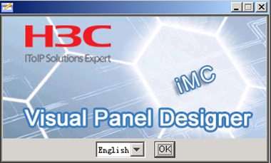
Log in to your Windows operating system as Administrator. Enter directory install, and then run installw.exe. A window appears for you to choose the language.
Figure 2-1 Select a language
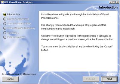
Select English and then click OK to enter the VPD introduction window.
Figure 2-2 Introduction
Click Next to enter the license agreement window.
Figure 2-3 License agreement
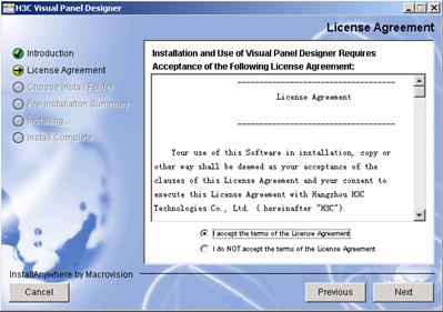
Read the license agreement carefully. Click I accept the terms of the License Agreement to proceed.
Figure 2-4 Choose install folder
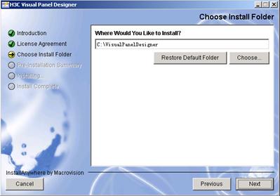
Select an installation folder and then click Next to enter the pre-installation summary window.
Figure 2-5 Pre-installation summary
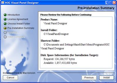
Click Install to enter the installing VPD window.
Figure 2-6 Installing Visual Panel Designer
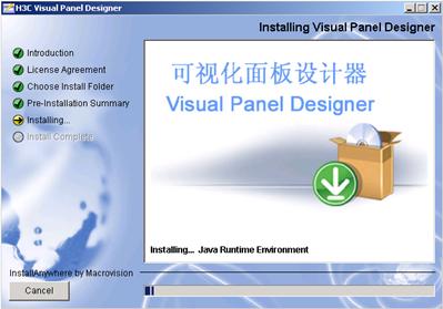
Wait until the installation is complete.
Figure 2-7 Install complete

Click Done.
Select Start > All Programs > H3C Visual Panel Designer > Uninstall Visual Panel Designer. The VPD uninstall wizard appears.
Figure 3-1 Uninstall H3C Visual Panel Designer
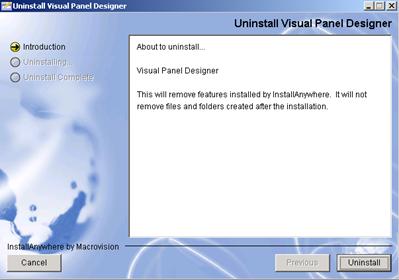
Click Uninstall to start the uninstallation process.
Figure 3-2 Uninstalling VPD
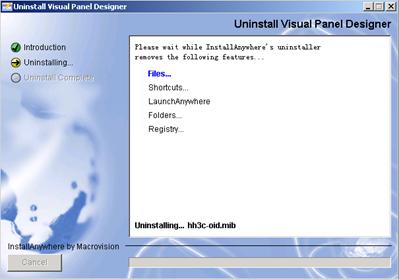
Wait until uninstallation is complete.
Figure 3-3 Uninstallation complete
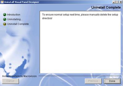
Click Done.
H3C VPD Overview
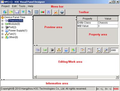
Toolbar: Provides the commonly used buttons listed as follows.
![]() New
Project: Creates a new project.
New
Project: Creates a new project.
![]() Open
Project: Opens an existing project.
Open
Project: Opens an existing project.
![]() Save
Project: Saves modification to a project.
Save
Project: Saves modification to a project.
![]() Export
Project: Exports a project in a zip package.
Export
Project: Exports a project in a zip package.
![]() Import
Project: Imports a project in a zip package to the VPD.
Import
Project: Imports a project in a zip package to the VPD.
![]() SNMP Configuration: Configures the MIB definition.
The system interacts with the device according to the MIB definition.
SNMP Configuration: Configures the MIB definition.
The system interacts with the device according to the MIB definition.
![]() Status Configuration: Configures the entity
status rule. Different colors indicate different statuses.
Status Configuration: Configures the entity
status rule. Different colors indicate different statuses.
![]() Find:
Searches for entities in the device panel tree by vendor type and/or name.
Find:
Searches for entities in the device panel tree by vendor type and/or name.
![]() MIB
Compiler: Compiles MIB files as JMIB files that can be recognized by iMC.
MIB
Compiler: Compiles MIB files as JMIB files that can be recognized by iMC.
![]() Set
Language: Sets the language of the VPD.
Set
Language: Sets the language of the VPD.
Device Panel Tree: In this area, you can create, delete, and customize entities. The common entity types include chassis, module, port, power supply, and fan. You can also customize new entity types as needed.
Preview area: Displays the entity selected from the device panel tree.
Property area: Allows you to view or edit the properties of the entity selected in the device panel tree or in the editing area.
Editing/work area: You can drag an entity to this area to edit it. The editing area provides the following buttons:
l
![]() Add Chassis: Adds a chassis.
Add Chassis: Adds a chassis.
l
![]() Add Module: Adds a module.
Add Module: Adds a module.
l
![]() Add
Port: Adds a port.
Add
Port: Adds a port.
l
![]() Add Fan: Adds a fan.
Add Fan: Adds a fan.
l
![]() Add Power Supply: Adds a power supply.
Add Power Supply: Adds a power supply.
l
![]() Add Other Entity: Customizes an entity.
Add Other Entity: Customizes an entity.
l
![]() Batch Add: Adds entities in batches.
Batch Add: Adds entities in batches.
l
![]() Rearrange: Rearranges the selected entities in the
editing area.
Rearrange: Rearranges the selected entities in the
editing area.
l
![]() Actual Size: Displays images in the actual size.
Actual Size: Displays images in the actual size.
l
![]() Zoom In/Out: Zooms in or zooms out on images. 1000 is
the actual image size.
Zoom In/Out: Zooms in or zooms out on images. 1000 is
the actual image size.
l
![]() Recover Data: Restores the data in the editing area to
the status before modification.
Recover Data: Restores the data in the editing area to
the status before modification.
l
![]() Clear Workspace: Removes the entity from
the editing area. You must clear the editing area before editing a new entity.
Clear Workspace: Removes the entity from
the editing area. You must clear the editing area before editing a new entity.
Information area: Displays the operation result (successful or failed).
Managing H3C VPD Projects
l
Log in to the iMC as an
administrator and enter the system management page. Then click the ![]() icon to enter the panel
management page.
icon to enter the panel
management page.
l The panel management page displays the enterprise IDs and names of the existing projects in iMC. You can import to the iMC a project exported from the VPD, or export an existing project from the iMC and edit it by using the VPD.
Figure 4-2 Panel management page

Displaying the Device Panel
l
Log in to the iMC, and enter
the details page of a device. Then click the ![]() icon to display the device panel.
icon to display the device panel.
l You can also display the device panel on the topology diagram.
Figure 4-3 Device panel
![]()
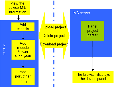
Figure 5-1 Operation flow
Using the VPD
This section describes the operations on the VPD.
Creating a Project
Shortcut key: Ctrl+N
Select Project > New Project to create a project.
Parameter description:
l Project name: You are recommended to specify a vendor name (such as HP) as the project name to better identify the project.
l Enterprise ID: Unique identifier for a vendor’s device. For example, the enterprise ID of an HP device is 11 and that of an H3C device is 25506.
l Dependent project: The VPD supports the dependence relationship between a sub-project and its parent project. A sub-project can use entities in the parent project. Typically a project is dependent on the system-defined project with enterprise ID 0. You can customize the dependence as needed.
Operation instruction: Select a project file suffixed with .prj.
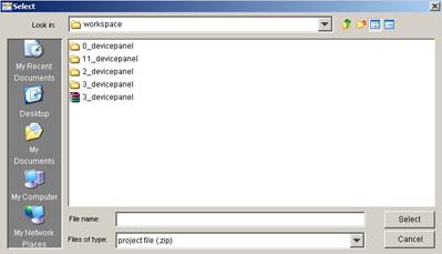
Opening a Project
Shortcut key: Ctrl+O
Select Project > Open Project to open a project.
Operation instruction: All projects are stored in the workspace directory preset by the VPD. Select a .prj file in this directory to open the project.
Entity Categories
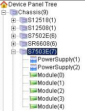
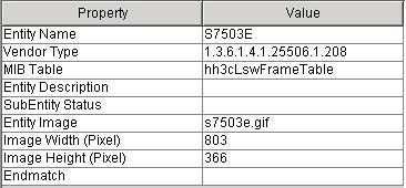
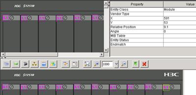
The entities in the VPD have two categories, physical and logical. In Figure 5-2, S7503E is a physical entity, and the modules and power supplies listed below are logical entities, which can be regarded as slots on the physical entity. You may install physical module or power supply entities into the slots. The physical vendor types are defined in the MIB.
Figure 5-2 S7503E in the device panel tree
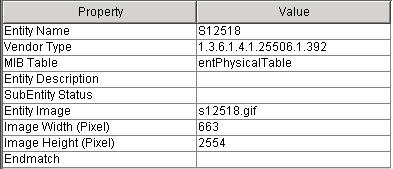
In the property column of a physical entity, as shown in Figure 5-3, MIB Table indicates where the sub-entity data of the entity is read. SubEntity Status indicates the status rule of the sub-entities.
Figure 5-3 Properties of the physical entity
In the property column of a logical entity, as shown in Figure 5-4, MIB Table indicates where the data of the entity in the device’s logical entity (slot) is read. For example, the value shows whether the power supply entity in the device’s slot 1 exists and where the entity is read. Entity Status indicates the status rule of the entity in the device’s logical entity (slot).
Figure 5-4 Properties of the logical entity

In this example, MIB Table of S7503E shows where the data of modules and power supplies is read, and SubEntity Status shows the status rule of the modules and power supplies on the switch. MIB Table of power supply 1 shows where power supply 1’s information is read, and Entity Status shows the status rule of power supply 1.
![]()
For an IRF virtual device, the MIB Table of a chassis shows where the chassis entity belongs. The MIB Table also shows where the sub-entities belong if they are in the same MIB table. In this case, you do not need to specify the MIB tables for the sub-entities.
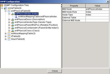
SNMP Configuration
1)
Click the ![]() icon in the toolbar (or
press the shortcut key Ctrl+M) to enter the SNMP configuration page. The SNMP configuration tree
is displayed on the left part and the property area is displayed on the right
part of the page.
icon in the toolbar (or
press the shortcut key Ctrl+M) to enter the SNMP configuration page. The SNMP configuration tree
is displayed on the left part and the property area is displayed on the right
part of the page.
Figure 5-5 SNMP configuration page
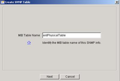
2) Select SNMP Configuration Tree > snmpTable. Then right-click and select Add to enter the Create SNMP Table page. Type the MIB table name.
Figure 5-6 Create SNMP table
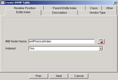
3) Click Next to display the Entity Index tab. An entity index is usually unique in the MIB table. MIB Node Name is an actual name defined in the MIB file. By making a selection in Indexed drop-down box, you can determine whether the node is to be indexed or not.
Figure 5-7 Entity Index tab
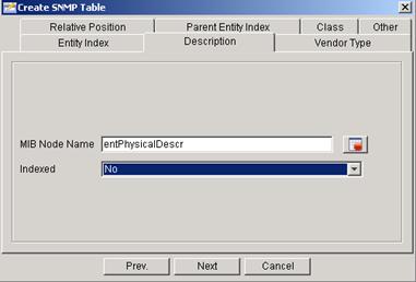
4) Select the Description tab. The description of an entity is displayed when you place the cursor over the entity in iMC.
Figure 5-8 Description tab
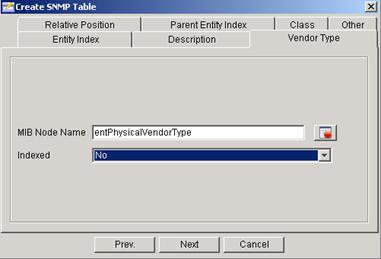
5) Select the Vendor Type tab. The vendor type is unique to each entity.
Figure 5-9 Vendor Type tab
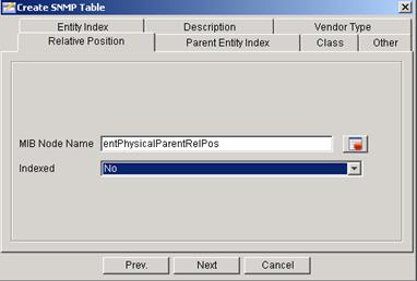
6) Select the Relative Position tab. Relative position indicates the sequence of the entity on its parent entity.
Figure 5-10 Relative Position tab
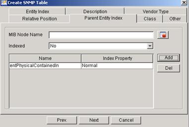
7) Select the Parent Entity Index tab. The parent entity index refers to the index of the current entity’s parent entity in the MIB table. You can configure one or more parent entity indexes. Click Add or Del to add or delete the parent entity index(es).
Figure 5-11 Parent Entity Index tab
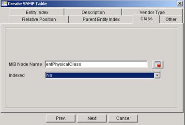
8) Select the Class tab. Entity class refers to the type of the entity, such as chassis, module, and port.
Figure 5-12 Class tab
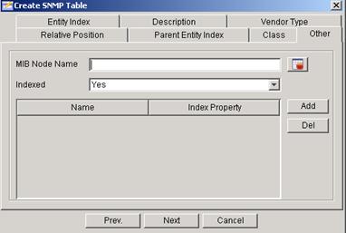
9) Select the Other tab. Other provides an option for you to create a node other than the above five nodes predefined in the MIB table.
Figure 5-13 Other tab
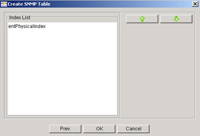
10) Click Next to enter the Index List page. You can arrange indexed nodes on this page to determine the sequence of the indexes in the MIB table.
Figure 5-14 Index List page
11) Click OK.
12) You can right-click a table name from the SNMP configuration tree to modify or delete the table.
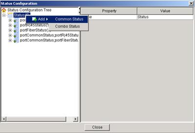
Status Configuration
1)
Click the ![]() icon in the toolbar (or
press the shortcut key Ctrl+T) to enter the status configuration page, and right-click Status
to add a status rule.
icon in the toolbar (or
press the shortcut key Ctrl+T) to enter the status configuration page, and right-click Status
to add a status rule.
Figure 5-15 Status configuration page
2) When configuring more than one nodes for a common status, separate the node names with semicolons. The status is determined by the specified nodes.
Figure 5-16 Common status properties
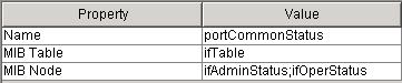
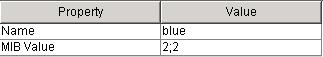
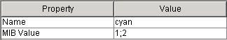
3) Right-click portCommonStatus from the status configuration tree to add the status rule. The display color of a port is determined by the ifAdminStatus and ifOperStatus nodes. If their values are both 1, the port is displayed in green (management and operating statuses). The port can also be displayed in blue or cyan.
Figure 5-17 Complete portCommonStatus rule


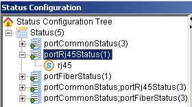
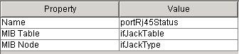
4) A combo status comprises of multiple common statuses. The following figure shows a combo status rule comprising a portCommonStatus rule and a portRj45Status rule. For example, a port with both the ifAdminStatus and ifOperStatus values being 1 is displayed in green. In the portRj45Status rule, the ifJackType node value is 2, so the port status is rj45. You get the green status with the portCommonStatus rule, and the rj45 status with the portRj45Status rule. The combo status of green;rj45 is green.
Figure 5-18 Combo status rule
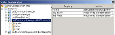
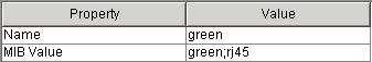
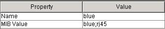
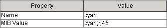
Figure 5-19 PortRj45Status rule
Uploading Images
The Entity Image property allows you to upload the entity image by clicking the … button.
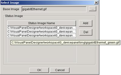
Figure 5-20 Entity image property
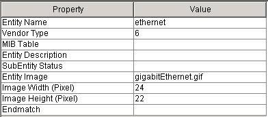
As shown in the following figure, the base image is the image used by the entity. If you have configured a status for an entity, you may need to upload multiple images. In this example, after configuring the portCommonStatus rule, upload three images according to the possible values green, blue, and cyan defined in the status rule. The image name must be in the format of base image_status value. The base image in this example is gigabitEthernet.gif. Therefore, the other three images are gigabitEthernet_green.gif, gigabitEthernet_blue.gif, and gigabitEthernet_cyan.gif.
Figure 5-21 Upload images
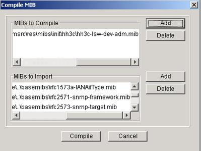
Compiling a MIB
Select Tools > MIB Compiler to compile a MIB.
Operation instruction: MIB compiling depends on certain basic MIBs that are predefined in the system. Before compiling a MIB, import all the MIB files related to the MIB. The information area gives detailed prompt information after you finish compiling the MIB.
Figure 5-22 Compile a MIB
Exporting a Project
Shortcut key: Ctrl+E
Select Project > Export Project to export a project.
Operation instruction: Select the directory you want to save the project, and then click Select Directory to save it. The system automatically opens the directory you selected.
Importing a Project
Shortcut key: Ctrl+I
Select Project > Import Project to import a project.
Figure 5-23 Import a project
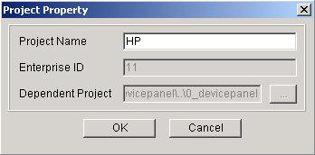
Configuring the Project Property
Shortcut key: Ctrl+P
Select Project > Project Property to configure the project property.
Operation instruction: You can modify the project name, and view the enterprise ID and dependent project. The project name helps you identify a project. Therefore, if the enterprise ID is 11 (represents HP), you are recommended to specify the vendor name HP as the project name.
Figure 5-24 Configure the project property
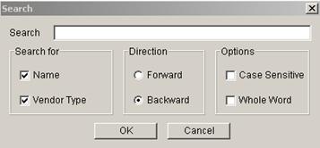
Finding Entities
Shortcut key: Ctrl+F
Select Edit > Find to enter the Search page.
Operation instruction: Search for entities by name and/or vendor type in the device panel tree. You can set the match option (case-sensitive and/or full match) and the search direction (forward or backward).
Figure 5-25 Find entities
Using VPD Projects in the iMC
This section describes the operations in the iMC. Suppose you have logged in to the iMC as an administrator.
VPD Management
Enter the system management page, and click
the device panel management icon (![]() ).
).
Operation instruction: This function allows you to browse, import, export, and delete VPD projects. Before deleting a project file, make sure no other project files are dependent on it. If you delete the parent project, you will encounter an error while parsing the relevant sub-projects.
Displaying the Device Panel
Select Resource > Device List > Operation > Open Device Panel.
Operation instruction: If the panel is not displayed as expected or is different from that of the actual device, check the project settings in the VPD according to the MIB.
HP ProCurve J9019A Switch 2510-24
The H3C VPD provides a simple support scheme for general low-end devices. The following takes HP ProCurve J9019A Switch 2510-24 as an example to describe how to configure the device panel information by using the H3C VPD.
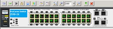
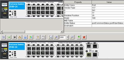
1) Figure 6-1 is the device panel picture of a device 2510-24. Draw the device panel picture as similar to the real device as possible (or just photo it). Make sure you draw the port slots to help you add port entities. From left to right on the panel, there is device model, a console port, LEDs, 24 Ethernet ports, two pairs of Combo ports, and a silkscreen print. This device supports RFC 1213. You can manage the elements on the panel, primarily the ports, by reading ifTable.
Figure 6-1 2510-24 device panel

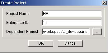
2) Run VPD and then select Project > New Project from the menu bar. The Create Project window appears. Type project name HP, enterprise ID 11, and select dependent project 0_devicepanel. Then click OK.
Figure 6-2 Create HP project
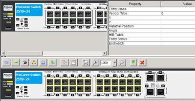
3) Right-click Chassis from the Device Panel Tree and click Add to add a device.
4) Edit the value of each property, as shown in Figure 6-3. You need to draw or photo the entity image beforehand.
Figure 6-3 Edit device properties
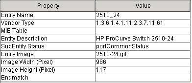
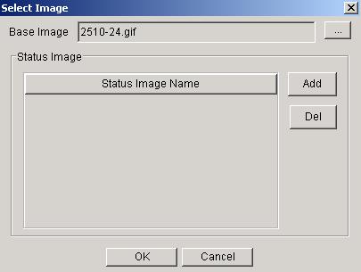
Figure 6-4 Select the entity image
5) Select device 2510_24 from the device panel tree. The device image appears at the preview area. Drag the image into the work area.
6)
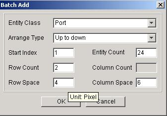
The device has 24 Ethernet ports. Click the Batch
Add icon (![]() )
in the work area to add port entities in a batch. Adjust the row space and
column space according to your image pixels. Click OK, and the added 24
Ethernet ports appear in the work area.
)
in the work area to add port entities in a batch. Adjust the row space and
column space according to your image pixels. Click OK, and the added 24
Ethernet ports appear in the work area.
Figure 6-5 Add ports in a batch
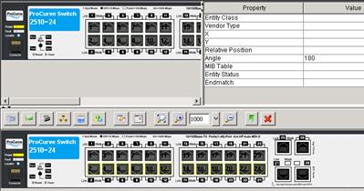
7) Drag the ports together to the right places on the panel. In this example, there is a gap between the first 12 ports and second 12 ports. Therefore, first adjust the positions of port 1 through port 12, and then select ports 13 to 24 and drag them together to the right places. You can press and hold down your left mouse button to select multiple ports. The selected ports will be marked with yellow border.
Figure 6-6 Adjust port positions
8) Select all 24 ports and change the vendor type to 6, the system default value for Ethernet ports.
Figure 6-7 Set the vendor type in a batch
![]()
If you do not set the vendor type of a port, the system reads the vendor type value from the device MIB. This requires you to use VPD to customize the port vendor type in advance.
9) Select all ports in the second row, and change Angle to 180, because these ports are inverted on the real panel.
Figure 6-8 Rotate ports in a batch
10)
Add Combo port 25: first click the Add Port
icon (![]() ) to add the electrical port. Drag it to the right place, change the
vendor type to 6, and select portCommonStatus;portRj45Status as the entity
status. Then, add the optical port in the same way and drag it to the port slot
under port 25. Change the vendor type to 117, relative position to 25, angle to
180, and entity status to portCommonStatus;portFiberStatus.
) to add the electrical port. Drag it to the right place, change the
vendor type to 6, and select portCommonStatus;portRj45Status as the entity
status. Then, add the optical port in the same way and drag it to the port slot
under port 25. Change the vendor type to 117, relative position to 25, angle to
180, and entity status to portCommonStatus;portFiberStatus.
Figure 6-9 Add the electrical port of Combo port 25
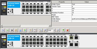
Figure 6-10 Add the optical port of Combo port 25
11) Add Combo port 26 in the same way.
12) If the system-predefined port types do not meet your requirements, add new port types.
13)
Click ![]() on the tool bar to save your object.
on the tool bar to save your object.
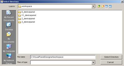
14) Select Project > Export Project from the menu bar. Select the export directory, and then click the Select Directory button. The system automatically opens the directory where the exported zip file resides.
Figure 6-11 Select a directory for saving the exported project
15)
Log in to the iMC as an administrator. Enter the
system management page, and click the device panel management icon (![]() ) to enter the VPD
project file management page.
) to enter the VPD
project file management page.
Figure 6-12 Device panel management
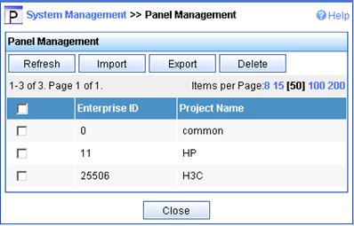
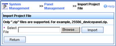
16) Click Import to enter the page for uploading a project file. Click Browse to select the exported zip package and then click Import. The system prompts successful import of file 11_devicepanel.zip.
Figure 6-13 Upload project file
17) Search the device by its IP. Click the operation icon and select Open Device Panel. Right-click the device panel and the system displays the supported functions and operations.
Figure 6-14 Device list
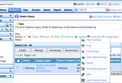
Figure 6-15 HP device panel

H3C S12518-S12508 IRF Virtual Device
The H3C VPD also supports designing device panels with multiple types of entities, such as ports, modules, power supplies, and fans, satisfying panel management requirements on medium- and high-end devices. The following takes an H3C S12518-S12508 IRF virtual device as an example to describe how to configure the device panel for a high-end device by using the H3C VPD.
1) The H3C S12500 series high-end devices support entityMIB and ifTable, making it possible for you to precisely manage the module, power supply, fan, and port entities. First, draw a picture for the entities to be managed, such as the device chassis and modules.
2) Create an H3C project. See the operation in section Creating a Project for reference. Change the enterprise ID to 25506.
3) Right-click Chassis from the device panel tree and click Add to add a device.
4) Edit the value of each property, as shown in Figure 6-16. You need to draw or photo the entity image beforehand.
Figure 6-16 Edit device properties
5) Select device S12518 from the device panel tree. The device image appears at the preview area. Drag the image to the work area. There are slots 0 to 29 on the device. Because the device supports entPhysicalTable, there must be information about power supplies and fans.
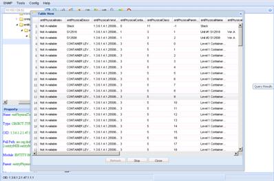
6) Use a MIB browsing tool to view the entPhysicalTable implementation on the device. You are recommended to use the MIB management function to view the information. To do so, log in to the iMC and then enter the system management page.
Figure 6-17 Table view by using the iMC MIB management tool
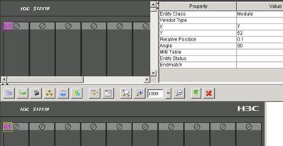
7)
Click the Add Module button (![]() ) in the work area, and
then drag the added virtual module entity to slot 0, and modify its properties.
Note: Set rotating angle to 90, because the modules we drew are horizontal. Set
the relative position to 0.1, which is consistent with that implemented in the
device entPhysicalTable. The S12518 device is represented in the form of
Stack->Chassis->Container->Module, where Container indicates the
module slot. As introduced previously, the entPhysicalParentRelPos node
represents the relative position of an entity on its parent entity. The
container here means the slot number. Usually, only one module is contained in
one slot, and thus the relative position of a module to a container is always
1. The relative position 0.1 here indicates module 1 in slot 0. This method
allows you to not add the Container entity, which does not exist actually.
) in the work area, and
then drag the added virtual module entity to slot 0, and modify its properties.
Note: Set rotating angle to 90, because the modules we drew are horizontal. Set
the relative position to 0.1, which is consistent with that implemented in the
device entPhysicalTable. The S12518 device is represented in the form of
Stack->Chassis->Container->Module, where Container indicates the
module slot. As introduced previously, the entPhysicalParentRelPos node
represents the relative position of an entity on its parent entity. The
container here means the slot number. Usually, only one module is contained in
one slot, and thus the relative position of a module to a container is always
1. The relative position 0.1 here indicates module 1 in slot 0. This method
allows you to not add the Container entity, which does not exist actually.
Figure 6-18 Add a module
8) Add all modules in the same way.
Figure 6-19 Add all modules
9) Add the power supplies and fans in the same way. The blue boxes represent power supplies and the white boxes represent fans.
Figure 6-20 Add power supplies and fans

10) Add module entity: right-click Module from the device panel tree and click Add. Set the module entity properties.
Figure 6-21 Module entity properties

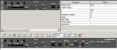
11) Drag the module image to the work area and then add a port. In this example, we create only one module entity. You can create multiple module entities as needed.
Figure 6-22 Add a port
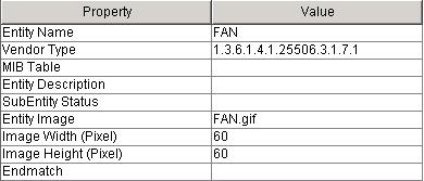
12) Add power supply and fan entities in the same way.
Figure 6-23 Add a power supply entity
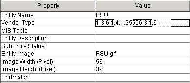
Figure 6-24 Add a fan entity
13) Add entities for the S12508 in the same way. Then save and export the project, import the project to the iMC, and then open the device panel. The S12518 panel is displayed at the upper part of the page. Under the S12518 panel is the S12508 panel.
Figure 6-25 S12518 device panel segment

How Can I Locate Entities Fast?
On a device, there may be modules with fixed positions, such as the module in slot 0 shown in Figure 7-1. To add such a module entity, you need to type the module vendor type value instead of leaving it blank (letting the system to read it from the device MIB).
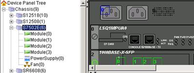
Figure 7-2 Locate entity
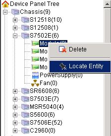
Figure 7-3 Vendor type of the module

When Uploading a New Project Created in VPD, I Was Prompted That the Project Already Exists in the iMC. What Shall I Do?
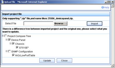
The new project you added in VPD has the same enterprise ID as the one uploaded to the iMC, however, the entities you defined for the new project are probably different from those of the project in the iMC. Therefore, when you upload the new project to the iMC, the new project and the existing project conflict. To address this issue, the iMC provides the project comparing function. That is, the iMC compares the newly uploaded project and the project that has the same enterprise ID in the iMC.
As shown in Figure 7-4, compared with the existing project, S7510E is added in the newly uploaded project and the definition of hh3cLswPortTable is also different. You can select the configuration you want to update as needed.
Figure 7-4 Compare the new project with the existing project
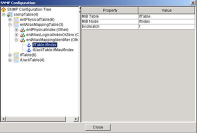
What Is the Endmatch Attribute in VPD Used for?
The endmatch attribute is typically used to process MIB object identifiers (OIDs). In most cases, MIB values on the device are complete MIB OIDs. For example, the complete MIB OID of an H3C interface module LSQ1CGP24TSC0 is 1.3.6.1.4.1.25506.3.1.9.4.570. However, the MIB may save only 570 as the card’s OID because the nodes before 570 are common to all H3C interface modules. At this time, you need to set the endmatch attribute to 1, meaning to match only the last part of the OID (separated into several parts by dots).
On the SNMP configuration page as shown in Figure 7-5, assume you want to associate the ifindex node in the ifTable with the entAliasMappingIdentifier node in the entAliasMappingTable. Because the entAliasMappingIdentifier node uses the complete OID for ifIndex, while the ifTable uses only the last part of the OID for ifindex, you need to set the endmatch attribute to 1 during the association.
Figure 7-5 Set the endmatch attribute
What Entities Does the Dependent Project 0_devicepanel Comprise?
The system provides a common project 0_devicepanel that defines some common entities, SNMP tables, and statuses.
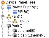
By default, the common project provides power module, fan, and port entities. An electrical port and an optical port, respectively with vendor type ethernetCsmacd(6) and gigabitEthernet (117) as defined in the IANAifType-MIB, are added to the project.
Figure 7-6 Pre-defined entities for the common project
The common project defines the following MIB tables:
1) entPhysicalTable, also called entity physical table, stores various physical entity data of the device. See Figure 7-7.
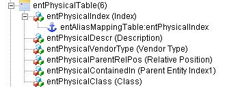
Description of the nodes:
l entPhysicalIndex: Index of the table, associated with the entPhysicalIndex node in the entAliasMappingTable. The two nodes share the same value.
l entPhysicalDescr: Description of each entity.
l entPhysicalVendorType: Unique identifier of an entity.
l entPhysicalParentRelPos: Relative position (sequence number) of the entity on its parent entity. For example, if an interface module provides 24 ports, Ethernet 0/1 through Ethernet 0/24, the relative position of Ethernet 0/5 on its parent entity is 5.
l entPhysicalContainedIn: entPhysicalIndex of a parent entity entry in the entPhysicalTable. It helps you locate the entry that the specific parent entity resides in entPhysicalTable.
l entPhysicalClass: Entity type, represented with numbers.
2) entAliasMappingTable associates the entPhysicalTable with the ifTable to show port status, as shown in Figure 7-8.
Figure 7-8 entAliasMappingTable
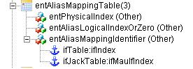
entPhysicalIndex in the entAliasMappingTable is associated with entPhysicalIndex in the entPhysicalTable. entAliasMappingIdentifier is associated with ifIndex in the ifTable and ifManuIfIndex in the ifJackTable.
3) ifTable stores port data of the device, as shown in Figure 7-9.
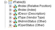
Description of the nodes:
l ifIndex: Index of the table. Many other tables reference the data in the ifTable based on the association with this index.
l ifDescr: Port description.
l ifType: Port type, which is defined in the IANAifType-MIB.
l ifAdminStatus: Management status of the port.
l ifOperStauts: Operating status of the port.
4) ifJackTable, as shown in Figure 7-10, mainly shows the combo port status. It is associated with the ifTable.
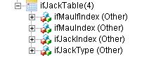
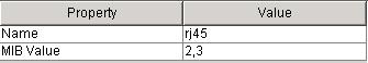
ifJackType shows the port type value. For example, rj45(2) or rj45S(3) indicates that the electrical port of the combo port is enabled; fiberSC(8), fiberMIC(9), or fiberST(10) indicates that the optical port of the combo port is enabled.
The common project defines the following statuses:
Figure 7-11 Statuses
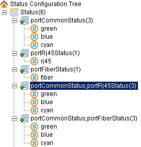
l portCommonStatus: Determined by the ifAdminStatus and ifOperStatus nodes. If their values are both 1, the port is displayed in green (use the image with name containing _green); if their values are both 2, the port is displayed in blue; if the ifAdminStatus is 1 and ifOperStatus is 2, the port is displayed in cyan.
l portRj45Status and portFiberStatus: Determined by the ifJackType node in the ifJackTable. The two nodes are typically used together to indicate the combo port status. If the ifJackType is 2 or 3, the electrical port is enabled, and the rj45 status is used; if the ifJackType is 8, 9, or 10, the optical port is enabled, and the fiber status is used.
l portCommonStatus; portRj45Status and portCommonStatus; portFiberStatus: portCommonStatus displays the port color, while portRj45Status and portFiberStatus display the electrical port and optical port. To use the status rule, set the same relative position for the two ports of the combo port (that means only one port is enabled at a time), set portCommonStatus; portRj45Status for the electrical port and portCommonStatus; portFiberStatus for the optical port. Then the current running port can be displayed in correct color.
