| Title | Size | Downloads |
|---|---|---|
| RDMA Technology White Paper-6W100-book.pdf | 256.62 KB |
- Table of Contents
- Related Documents
-
RDMA Technology White Paper
Copyright © 2019 New H3C Technologies Co., Ltd. All rights reserved.
No part of this manual may be reproduced or transmitted in any form or by any means without prior written consent of New H3C Technologies Co., Ltd.
Except for the trademarks of New H3C Technologies Co., Ltd., any trademarks that may be mentioned in this document are the property of their respective owners.
The information in this document is subject to change without notice.
Building a lossless Ethernet network· 4
Key features for building a lossless Ethernet network· 4
Example: Building a lossless Ethernet network· 14
Overview
Technical background
High-performance computing (HPC), big data analysis, artificial intelligence (AI), and Internet of Things (IoT) are developing fast, and the centralized/distributed storage and cloud databases are widely used. As a result, service applications need to obtain more and more data from networks, leading to higher requirement for the switching speed and performance of datacenter networks.
In traditional TCP/IP software and hardware architectures and applications, the network transmission and data processing delays are long, data are copied and interrupted multiple times, and TCP/IP protocol processing is complicated. Remote Direct Memory Access (RDMA) reduces the data processing delay on servers during the network transmission process. RDMA directly transmits the user application data to the storage space of the servers, and uses the network to fast transmit the data from the local system to the storage of the remote system. RDMA eliminates multiple data copying and context switching operations during the transmission process, and reduces the CPU load.
Figure 1 Traditional TCP/IP data transmission process
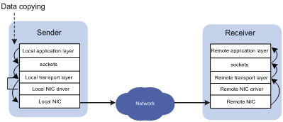
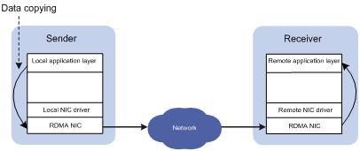
Figure 2 RDMA data transmission process
Benefits
During the network transmission process, RDMA directly transmits data between the data buffers of two nodes. RDMA directly transmits data on the local node to the memory of the remote node, bypassing multiple data copying operations in the CPU by the operating systems. Compared with traditional network transmission technologies, RDMA does not involve operating systems or TCP/IP protocols, and easily implements low-latency data processing and high throughput. Because RDMA does not involve the CPU resources of remote nodes, RDMA saves resources for data migration and processing.
RDMA technique types
RDMA techniques include the following types:
· IB—InfiniBand, an RDMA technique based on the InfiniBand architecture, which is proposed by InfiniBand Trade Association (IBTA). To build an IB-based RDMA network, you need dedicated IB NICs and IB switches.
· iWARP—Internet Wide Area RDMA Protocol, an RDMA technique based on TCP/IP protocols, which is proposed by IETF. iWARP supports RDMA on standard Ethernet infrastructures. However, the servers must use iWARP-capable NICs.
· RoCE—RDMA over Converged Ethernet, an RDMA technique based on Ethernet, which is also proposed by IBTA. RoCE supports RDMA on standard Ethernet infrastructures. However, the Ethernet switches must support lossless Ethernet and the servers must use RoCE NICs.
H3C Ethernet switches support iWARP. Some H3C switches support lossless Ethernet, and thus support RoCE. For devices that support lossless Ethernet, consult the marketing staff or see the product documents.
RDMA technique overview
IB
Introduction
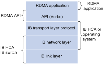
IB is an RDMA technique based on the InfiniBand architecture. IB provides a channel-based point-to-point message queuing forwarding model. Each application can directly obtain its own data messages through the created virtual channel, without involving other operating systems or protocol stacks. On the application layer, IB uses RDMA to provide direct read/write access to the remote nodes and completely offload the CPU. On the network layer, IB provides high-bandwidth transmission. On the link layer, IB provides a dedicated retransmission mechanism to guarantee QoS, and does not need buffering data.
IB must run in an IB network using IB switches and IB NICs.
Figure 3 IB architecture
Benefits
IB delivers the following benefits:
· Uses RDMA on the application layer to reduce the data processing delay on the host side.
· Controls message forwarding by using the subnet manager, without complicated protocol interactions and calculations in Ethernet.
· Uses a retransmission mechanism on the link layer to guarantee QoS, not buffers packets, and achieves zero packet loss.
· Achieves low latency, high bandwidth, and low overhead.
iWARP
Introduction
iWARP is an RDMA technique based on Ethernet, and can run on a standard Ethernet infrastructure.
iWARP contains the following layers:
· RDMAP—RDMA protocol, which performs RDMA read/write operations and translates RDMA messages, and sends RDMA messages to the DDP layer.
· DDP—Direct data placement, which segments long RDMA messages, encapsulates the segments in DDP PDUs, and sends the packets to the MPA layer.
· MPA—Marker PDU aligned framing, which adds markers at the fixed octet intervals, data packet length fields, and CRC fields to DDP PDUs to form MPA PDUs and sends them to TCP for transmission.
Benefits
iWARP reduces the network load on the host side in the following aspects:
· Offloads TCP/IP processing from the CPU to the RDMA NIC, reducing the CPU load.
· Eliminates memory copying. An application can directly transmits its data to the memory of an application on the remote end, sharply reducing the CPU load.
· Reduces context switching for application programs. An application can bypass the operating system and directly issue commands to the RDMA NIC in the user space, reducing the overheads and the delay caused by application context switching.
Because TCP protocols can provide flow control and congestion management, iWARP does not need to support lossless Ethernet, and can be implemented by common Ethernet switches and iWARP NICs. Therefore, iWARP can be used in WANs and easily expanded.
RoCE
Introduction
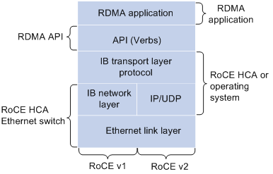
RoCE supports carrying IB over Ethernet to implement RDMA over Ethernet. RoCE and IB are the same on the application layer and transport layer, and are different only on the network layer and Ethernet link layer.
Figure 4 RoCE architecture
RoCE has the following versions:
· RoCEv1—Carries RDMA over Ethernet. RoCEv1 can be deployed only on Layer 2 networks. RoCEv1 adds Layer 2 Ethernet headers to IB packets and identifies RoCE packets by using Ethertype 0x8915.
· RoCEv2—Carries RDMA over UDP/IP protocols. RoCEv2 can be deployed on Layer 3 networks. RoCEv2 adds UDP headers, IP headers, and Layer 2 Ethernet headers to IB packets, and identifies RoCE packets by using destination UDP port number 4791. RoCEv2 supports hashing based on source port numbers and uses ECMP to implement load sharing, improving the network efficiency.
Benefits
RoCE delivers the following benefits for data transmission over Ethernet:
· High throughput.
· Low latency.
· Low CPU load.
RoCE can be implemented through common Ethernet switches. However, the servers must use RoCE NICs and the network must support lossless Ethernet because loss of any packet will cause a large number of retransmissions in IB and seriously affect the data transmission performance.
Building a lossless Ethernet network
Key features for building a lossless Ethernet network
In an RoCE network, you must build a lossless Ethernet network to ensure zero packet loss. Lossless Ethernet must support the following key features:
· (Required.) PFC—Priority-based Flow Control. PFC provides per-hop priority-based flow control for multiple types of traffic separately.
· (Required.) ECN—Explicit Congestion Notification. When the device is congested, ECN marks the ECN field in the IP header of a packet. The receiver sends congestion notification packets (CNPs) to notify the sender to slow down the sending speed. ECN implements end-to-end congestion management and reduces the spread and deterioration of congestion.
· (Recommended.) DCBX—Data Center Bridging Capability Exchange Protocol. DCBX uses LLDP to autonegotiate DCB capabilities, including PFC and ETS capabilities. Typically, DCBX is used on the interface connecting the switch to the server, and negotiates capabilities with the server NIC.
· (Optional.) ETS—Enhanced Transmission Selection. ETS classifies traffic by service type, provides minimum guaranteed bandwidth for different traffic types, and improves the link utilization. ETS must be configured hop by hop.
Figure 5 Key features for building a lossless Ethernet
In an RoCE network, PFC must be used together with ECN to guarantee both zero packet loss and bandwidth. Table 1 compares PFC and ECN.
Item | PFC | ECN |
Network location | Layer 2 | Network layer and transport layer |
Effective scope | Point-to-point | End-to-end |
Needs network-wide support or not | Yes | No |
Controlled objects | Previous node in the network (if the server NIC supports PFC, PFC also takes effect on the NIC) | Sender host |
Packet buffer location | Intermediate nodes and sender | Sender |
Affected traffic | All traffic in one of the eight queues on the device | Congested connection |
Response speed | Fast | Slow |
PFC
Introduction
PFC is required for building a lossless Ethernet network. PFC provides per-hop priority-based flow control. When the device is forwarding packets, the device assigns packets to queues for scheduling and forwarding through looking up packet priorities in priority mapping tables. When the sending rate of packets carrying an 802.1p priority exceeds the receiving rate and the data buffer space on the receiver is insufficient, the receiver sends PFC pause frames to the sender. When the sender receives the PFC pause frames, the sender stops sending packets with the specified 802.1p priority until the sender receives PFC XON frames or the aging timer expires. When PFC is configured, the congestion of packets of a specific type does not affect the normal forwarding of the other types of packets, and different types of packets on a link are forwarded independently.
Mechanism
PFC pause frame generation mechanism
Figure 6 How PFC frames are generated
As shown in Figure 6, PFC frames are generated in the following process:
1. When Port 1 of Device B receives packets from Device A, the memory management unit (MMU) of Device B allocates cell resources to the packets. If PFC is enabled on Device B, Device B counts the cell resources occupied by packets with each 802.1p priority.
| NOTE: Cell resources are used to store packets. An interface allocates cell resources to packets based on packet sizes. Suppose a cell resource provides 208 bytes. An interface allocates one cell resource to a 128-byte packet and two cell resources to a 300-byte packet. |
2. When the cell resources used by packets carrying a certain 802.1p priority exceed the set threshold on Port 1 of Device B, Port 1 of Device B sends PFC pause frames for the 802.1p priority to Device A.
3. When Device A receives the PFC pause frames for the 802.1p priority, Device A stops sending out packets carrying the 802.1p priority and buffers these packets. If the buffer threshold for the 802.1p priority is reached, Device A sends PFC pause frames for the 802.1p priority to its upstream device, as shown in Figure 7.
Figure 7 PFC frame processing between multiple devices
Packet priority-to-queue mappings
When a device forwards packets, packets with different priority values are assigned to different queues for scheduling and forwarding. The packet priority-to-queue mappings depend on the priority mapping method configured. The device supports the following priority mapping methods:
· Configuring priority trust mode—In this method, you can configure an interface to trust the specified type of priority carried in packets. Then, the device looks up the trusted priority type in incoming packets in the priority maps and modifies the priority values in packets based on the priority maps. Packets are scheduled within the device based on the priorities. Available priority trust modes include:
¡ dot1p—Trusts the 802.1p priority carried in packets and uses the 802.1p priority for priority mapping.
¡ dscp—Trusts the DSCP priority carried in IP packets and uses the DSCP priority for priority mapping.
· Changing port priority—If no priority trust mode is configured for an incoming interface, the port priority of the incoming interface is used for priority mapping. By changing the port priority of an interface, you can change the priority of incoming packets on the interface. Then, packets received on different incoming interfaces can be assigned to the corresponding queues and scheduled differentiatedly.
When configuring PFC on an interface, you must configure the interface to trust the 802.1p or DSCP priority carried in packets. When the interface receives Ethernet packets, the interface marks local precedence values for packets according to the priority trust mode and the 802.1Q tagging status of packets. Then, the packets are scheduled based on their local precedence values. Figure 8 shows the detailed process.
| NOTE: This document describes only the packet priority to local precedence mappings when the interface trusts the 802.1p or DSCP priority carried in packets. For information about the port priority configuration and the drop precedence (used as a reference for dropping packets), see the configuration guide for your device. |
Figure 8 Packet priority to queue mappings
For PFC to work properly on an interface, you must configure the interface to trust the 802.1p or DSCP priority carried in packets, and make sure the 802.1p-to-local priority map and DSCP-to-802.1p priority map are the same on all interfaces along the transmission path.
Extended PFC features
PFC threshold settings
By configuring the PFC buffer thresholds, you can avoid tail drop in the sending data buffer when the buffer space is insufficient for incoming packets.
The storage spaces for an interface include the following types:
· Guaranteed storage space—Minimum storage space guaranteed for each priority queue of each interface. The system allocates the specified space to each queue as configured. Even when a queue does not need to store packets, the other queues cannot preempt the guaranteed storage space of the queue. The space guaranteed for a queue is evenly allocated among interfaces. Even when a queue on an interface does not need to store packets, the queue on the other interfaces cannot preempt the space.
· Shared storage space—When the guaranteed buffer space for an interface or priority is insufficient, the shared storage space is used. The system determines the space that each queue can use based on the user configuration and the number of packets to be sent or received. If a queue does not need to store packets, the shared storage space of the queue can be preempted by other queues. The shared storage space of a queue is preempted by received or sent packets of all interfaces in first come first served way. When the resources are used out, the subsequent packets are dropped.
· Headroom storage space—When PFC takes effect on an interface and the PFC back pressure frame threshold is triggered, the local device sends PFC pause frames to notify the peer device to stop sending packets with the specified priority. The headroom storage space is used for storing the packets being transmitted on the path to avoid packet loss in the PFC process before the peer device stops sending packets.
The device supports the following PFC thresholds:
· Headroom buffer threshold—Maximum number of cell resources that can be used by packets with a specific 802.1p priority value in a headroom storage space. An interface drops received packets once this threshold is reached.
· Back pressure frame triggering threshold—Maximum number of cell resources that can be used by packets with a specific 802.1p priority value in a shared storage space. PFC is triggered once this threshold is reached. The back pressure frame triggering threshold includes the following types:
¡ Dynamic back pressure frame triggering threshold—Maximum cell resources set in percentage.
¡ Static back pressure frame triggering threshold—Maximum cell resources set in an absolute value.
· Offset between the back pressure frame stopping threshold and triggering threshold—When the number of cell resources used decreases by this offset after PFC is triggered, PFC will be stopped.
· PFC reserved threshold—Number of cell resources reserved for packets with a specific 802.1p priority value in a guaranteed storage space.
· Maximum number of cell resources in a headroom storage space—Number of cell resources allocated to the headroom storage space in a storage pool.
For more information about the configuration commands, see the configuration guide and command reference for your device.
| NOTE: The recommended headroom space thresholds depend on the interface transmission speed and distance. For the recommended values, see the command reference for your device. After PFC is enabled for 802.1p priorities, the other PFC thresholds use the default values, which are adequate in typical network environments. As a best practice, change the thresholds only when necessary. If the network environment or traffic is complicated, consult the professionals to adjust the PFC thresholds. |
PFC deadlock detection
When packets carrying the specified 802.1p priority are transmitted in a loop, packets in the data buffer cannot be forwarded and PFC frames are repeatedly transmitted between devices. As a result, the cell resources in the buffer for device interfaces always cannot be released. In this case, the device enters the PFC deadlock state. To remove the PFC deadlock, disable PFC or ignore the received PFC XOFF frames (which are used to notify the device to stop sending packets) to resume packet sending on the device.
PFC deadlock detection periodically detects whether the device is in the PFC deadlock state. When PFC deadlock is detected on a device, the device automatically releases the deadlock state after the delay timer expires. During the delay timer period, the device automatically disables PFC deadlock detection temporarily, so that packets can be forwarded properly.
After the PFC deadlock state is released, the PFC deadlock detection feature can be recovered on an interface automatically or manually. Recovering this feature enables the PFC feature again at the same time. Use the automatic recovery mode when no serious failures occur. When a packet loop cannot be eliminated and the device enters PFC deadlock state frequently, set the PFC deadlock detection recovery mode to manual on the interface. Then, troubleshoot the device, and recover the PFC deadlock detection and PFC features.
For more information about PFC deadlock detection configuration and commands, see the command reference and configuration guide for your device.
PFC one-key escape
When emergent failures occur to the PFC feature on the device, you do not need to disable PFC on interfaces one by one. Instead, you can one-key disable PFC on all interfaces at the CLI. After the failures are removed, you can one-key enable PFC on all interfaces at the CLI. The command syntax varies by device model.
PFC frame warning thresholds
You can configure the early warning thresholds for incoming or outgoing PFC frames according to the network conditions. The early warning threshold notifies a situation where the PFC frame transmission rate is still within a normal range but needs attention.
When the rate of PFC frames that an interface sends or receives reaches the early warning threshold, the system generates traps and logs to notify the user. According to the traps and logs, the user can discover some exceptions in the network, for example:
· The NIC of the peer device fails and continuously sends PFC frames at a high speed. In this case, you can set the early warning threshold for incoming PFC frames.
· The device fails and continuously sends PFC frames. In this case, you can set the early warning threshold for outgoing PFC frames.
To monitor bidirectional PFC frames, you can set the early warning thresholds for incoming packets and outgoing packets separately.
For more information, see the manual for your device.
Reporting statistics and alarms by cooperating with gRPC
PFC can cooperate with gRPC to actively report packet loss alarms and threshold crossing alarms. Additionally, PFC can cooperate with gRPC to provide packet loss statistics and realtime used values for querying.
The following statistics can be reported:
· Total ingress/egress lost packets.
· Total number of Rx/Tx PFC frames and the Rx/Tx frame rates.
· Ingress/egress buffer usage.
· Headroom buffer usage.
· Ingress/egress buffer threshold crossing times.
· Headroom threshold crossing times.
· XPE-based buffer usage.
· ECN marked times.
· Total number of packets dropped by WRED.
The following alarms can be reported:
· Ingress/egress packet loss alarms.
· Headroom buffer threshold crossing alarms.
· Ingress buffer threshold crossing alarms.
· Egress buffer threshold crossing alarms.
Rich diagnosis and maintenance functions
Use the display priority-flow-control command to display PFC configuration on an interface and the number and rate of sent/received PFC frames for each queue of each interface.
Use the display packet-drop command to display the total number of incoming/outgoing packets dropped and the packets dropped on each interface.
Use the display qos queue-statistics interface outbound command to display outgoing packet statistics collected for an interface on a per-queue basis.
ECN
Introduction
ECN is required for building a lossless Ethernet network. ECN defines a traffic control and end-to-end congestion notification mechanism based on the IP layer and transport layer. ECN uses the DS field in the IP header to mark the congestion status along the packet transmission path. An ECN-capable terminal can determine whether congestion occurs on the transmission path according to the packet contents. Then, the terminal adjusts the packet sending speed to avoid deteriorating congestion.
Mechanism
ECN defines the last two bits (ECN field) in the DS field of the IP header as follows:
· Bit 6 indicates whether the sending terminal device supports ECN, and is called the ECN-Capable Transport (ECT) bit.
· Bit 7 indicates whether the packet has experienced congestion along the transmission path, and is called the Congestion Experienced (CE) bit.
| NOTE: In actual applications, the following packets are considered as packets that an ECN-capable terminal sends: · Packets with ECT set to 1 and CE set to 0. · Packets with ECT set to 0 and CE set to 1. |
Figure 9 DS field location
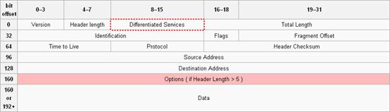
Figure 10 ECN field location
![]()
After you enable ECN on a device, congestion management processes packets as follows:
· When the average queue size is below the lower threshold, no packet is dropped, and the ECN fields of packets are not identified or marked.
· When the average queue size is between the lower threshold and the upper threshold, the device performs the following operations:
a. Picks out packets to be dropped according to the drop probability.
b. Examines the ECN fields of these packets and determines whether to drop these packets.
- If the ECN field shows that the packet is sent out of an ECN-capable terminal, the device sets both the ECT bit and the CE bit to 1 and forwards the packet.
- If both the ECT bit and the CE bit are 1 in the packet, the device forwards the packet without modifying the ECN field. The combination of ECT bit 1 and CE bit 1 indicates that the packet has experienced congestion along the transmission path.
- If both the ECT bit and the CE bit is 0 in the packet, the device drops the packet.
· When the average queue size exceeds the upper threshold, the device sets the ECN field to 11 for all packets in the queue and drops the packets exceeding the upper threshold.
Figure 11 ECN working mechanism
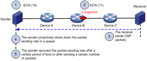
ECN works in the following flow:
1. The sender sets the ECN field to 10, and notifies the devices along the transmission and the receiver that the sender supports ECN.
2. When congestion occurs on an intermediate device, the congested device sets the ECN field to 11 for congested packets, and normally forwards the packets.
3. When the receiver receives packets with the ECN field set to 11, the transport layer sends congestion notification packets (CNPs) to the sender.
4. When receiving the CNPs, the sender slows down the sending rate of packets with the specified priority.
5. After a configurable period of time or the specified number of packets are sent, the sender resumes the original sending rate.
DCBX
Introduction
DCBX is a key feature for building a lossless Ethernet network. Data center Ethernet (DCE) uses Data Center Bridging Exchange Protocol (DCBX) to negotiate and remotely configure the bridging capabilities of network elements. With DCBX, DCB parameters can be negotiated and automatically configured between switches or switches and NICs. DCBX simplifies the network configuration and guarantees configuration consistency.
Mechanism
Figure 12 DCBX configuration in a network
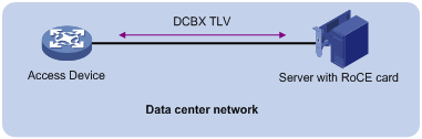
DCBX uses Link Layer Discovery Protocol (LLDP) to exchange configuration information between two ends of a link.
To enable DCBX on an interface, first enable LLDP globally and on the interface, and configure the interface to advertise DCBX TLVs. Then, you can configure DCBX to advertise Application Protocol (APP), Enhanced Transmission Selection (ETS), and PFC parameters on the interface as needed. In this document, DCBX is used to advertise ETS parameters.
When configuring DCBX, you must configure the DCBX version, which can be manually configured or autonegotiated. For DCBX to work properly, make sure the DCBX version is the same on the local and peer devices.
ETS
Introduction
ETS allocates bandwidth based on priority groups and provides committed bandwidth. To avoid packet loss caused by congestion, the device performs the following operations:
1. Uses ETS parameters to negotiate with the peer device.
2. Controls the peer device's transmission speed of the specified type of traffic.
3. Guarantees that the transmission speed is within the committed bandwidth of the interface.
Mechanism
ETS classifies the priorities of traffic in the network into multiple priority groups and allocates certain bandwidth to each priority group. If the bandwidth allocated to a priority group is not used, the other priority groups can use the unused bandwidth. ETS guarantees bandwidth for important traffic during the transmission procedure.
To configure ETS parameters, perform the following tasks:
1. Configure the 802.1p-to-local priority mapping by using either of the following methods:
¡ MQC method.
¡ Priority mapping table method.
If you configure the 802.1p-to-local priority mapping in both methods, the configuration made in the MQC method applies. For the QoS policy and priority mapping table configuration commands, see the manual for your device.
2. Configure group-based WRR queuing to allocate bandwidth. For information about WRR configuration commands, see the manual for your device.
WRR queuing schedules all the queues in turn to ensure that every queue is served for a certain time. Assume an interface provides eight output queues. WRR assigns each queue a weight value (represented by w7, w6, w5, w4, w3, w2, w1, or w0). The weight value of a queue decides the proportion of resources assigned to the queue. On a 100 Mbps interface, you can set the weight values to 50, 50, 30, 30, 10, 10, 10, and 10 for w7 through w0. In this way, the queue with the lowest priority can get a minimum of 5 Mbps of bandwidth.
Another advantage of WRR queuing is that when the queues are scheduled in turn, the service time for each queue is not fixed. If a queue is empty, the next queue will be scheduled immediately. This improves bandwidth resource use efficiency.
WRR queuing includes the following types:
¡ Basic WRR queuing—Contains multiple queues. You can set the weight for each queue, and WRR schedules these queues based on the user-defined parameters in a round robin manner.
¡ Group-based WRR queuing—All the queues are scheduled by WRR. You can divide output queues to WRR priority queue group 1 and WRR priority queue group 2. Round robin queue scheduling is performed for group 1 first. If group 1 is empty, round robin queue scheduling is performed for group 2. Only WRR priority queue group 1 is supported in the current software version.
On an interface enabled with group-based WRR queuing, you can assign queues to the SP group. Queues in the SP group are scheduled with SP. The SP group has higher scheduling priority than the WRR groups.
To configure ETS to guarantee bandwidth for important traffic, you can configure group-based WRR queueing in one of the following methods:
· Configure a higher weight value for the queue of important traffic in WRR priority queue group 1.
qos wrr queue-id group 1 byte-count schedule-value
· Assign the queue of important traffic to the SP group.
qos wrr queue-id group sp
Example: Building a lossless Ethernet network
Network configuration
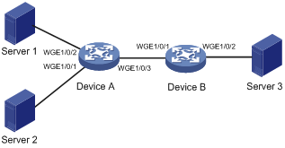
As shown in Figure 13, Server 1, Server 2, and Server 3 all have RoCE NICs installed. Server 1 and Server 2 are connected to Server 3 through Device A and Device B.
Configure the network as a lossless Ethernet network to support RoCE as follows:
· Enable PFC on all interfaces along the packet transmission paths. This example enables lossless transmission for packets with 802.1p priority 5.
· Enable DCBX on the interfaces connecting switches to servers, so that the switches and server NICs can negotiate ETS and PFC parameters.
· Configure ETS to guarantee bandwidth for packets with 802.1p priority 5 on Twenty-FiveGigE 1/0/3 of Device A and Twenty-FiveGigE 1/0/2 and Device B.
| NOTE: In this example, suppose the traffic from Server 1 and Server 2 to Server 3 is more than the reverse traffic. Therefore, ETS is configured only on the interfaces mentioned above. If traffic is unpredictable in actual conditions, you can configure ETS on all interfaces in the network. |
· Configure ECN on Twenty-FiveGigE 1/0/3 of Device A, so that Device A can notify the senders to adjust the packet sending rate when congestion occurs on Device A.
| NOTE: In this example, congestion might occur on Twenty-FiveGigE 1/0/3 of Device A, so ECN is configured only on the interface. If the congestion positions are unpredictable in actual conditions, you can configure ECN on all interfaces in the network. |
Procedures
1. Configure Device A:
# Configure Twenty-FiveGigE 1/0/1, Twenty-FiveGigE 1/0/2, and Twenty-FiveGigE 1/0/3 to trust 802.1p priorities carried in packets. Enable PFC and enable PFC for 802.1p priority 5 on these interfaces.
<DeviceA> system-view
[DeviceA] interface range twenty-fivegige 1/0/1 to twenty-fivegige 1/0/3
[DeviceA-if-range] qos trust dot1p
[DeviceA-if-range] priority-flow-control enable
[DeviceA-if-range] priority-flow-control no-drop dot1p 5
[DeviceA-if-range] quit
# Enable LLDP globally.
[DeviceA] lldp global enable
# Enable LLDP on Twenty-FiveGigE 1/0/1 and Twenty-FiveGigE 1/0/2. Enable these interfaces to advertise DCBX TLVs. Set the DCBX version to Rev. 1.01 on these interfaces.
[DeviceA] interface range twenty-fivegige 1/0/1 to twenty-fivegige 1/0/2
[DeviceA-if-range] lldp enable
[DeviceA-if-range] lldp tlv-enable dot1-tlv dcbx
[DeviceA-if-range] dcbx version rev101
[DeviceA-if-range] quit
# Enable byte-count WRR on Twenty-FiveGigE 1/0/3. Assign queue 5 (802.1p priority 5 is mapped to local precedence 5 by default) to the SP group.
[DeviceA] interface twenty-fivegige 1/0/3
[DeviceA-Twenty-FiveGigE1/0/3] qos wrr byte-count
[DeviceA-Twenty-FiveGigE1/0/3] qos wrr 5 group sp
[DeviceA-Twenty-FiveGigE1/0/3] quit
# Create WRED table queue-table5. In the WRED table, set the exponent for WRED to calculate the average queue size and WRED parameters, and enable ECN for queue 5. Apply WRED table queue-table5 to Twenty-FiveGigE 1/0/3.
[DeviceA] qos wred queue table queue-table5
[DeviceA-wred-table-queue-table5] queue 5 weighting-constant 12
[DeviceA-wred-table-queue-table5] queue 5 drop-level 0 low-limit 10 high-limit 20 discard-probability 30
[DeviceA-wred-table-queue-table5] queue 5 ecn
[DeviceA-wred-table-queue-table5] quit
[DeviceA] interface twenty-fivegige 1/0/3
[DeviceA-Twenty-FiveGigE1/0/3] qos wred apply queue-table5
2. Configure Device B:
# Configure Twenty-FiveGigE 1/0/1 and Twenty-FiveGigE 1/0/2 to trust 802.1p priorities carried in packets. Enable PFC and enable PFC for 802.1p priority 5 on these interfaces.
<DeviceB> system-view
[DeviceB] interface range twenty-fivegige 1/0/1 to twenty-fivegige 1/0/2
[DeviceB-if-range] qos trust dot1p
[DeviceB-if-range] priority-flow-control enable
[DeviceB-if-range] priority-flow-control no-drop dot1p 5
[DeviceB-if-range] quit
# Enable LLDP globally.
[DeviceB] lldp global enable
# Enable LLDP on Twenty-FiveGigE 1/0/2. Enable the interface to advertise DCBX TLVs. Set the DCBX version to Rev. 1.01 on the interface.
[DeviceB]interface twenty-fivegige 1/0/2
[DeviceB-Twenty-FiveGigE1/0/2] lldp enable
[DeviceB-Twenty-FiveGigE1/0/2] lldp tlv-enable dot1-tlv dcbx
[DeviceB-Twenty-FiveGigE1/0/2] dcbx version rev101
[DeviceB-Twenty-FiveGigE1/0/2] quit
# Enable byte-count WRR on Twenty-FiveGigE 1/0/2. Assign queue 5 (802.1p priority 5 is mapped to local precedence 5 by default) to the SP group.
[DeviceB] interface twenty-fivegige 1/0/2
[DeviceB-Twenty-FiveGigE1/0/2] qos wrr byte-count
[DeviceB-Twenty-FiveGigE1/0/2] qos wrr 5 group sp
Verification
# Display information about packets dropped on Device B.
<DeviceB> display packet-drop summary
All interfaces:
Packets dropped due to Fast Filter Processor (FFP): 0
Packets dropped due to STP non-forwarding state: 0
Packets dropped due to insufficient data buffer. Input dropped: 0 Output dropped: 0
Packets of ECN marked: 1622267130
Packets of WRED droped: 0
The output shows that zero packets are dropped on Device B.
# Display the bandwidth usage of Twenty-FiveGigE 1/0/2 on Device B.
<DeviceB> display counters rate outbound interface Twenty-FiveGigE 1/0/2
Usage: Bandwidth utilization in percentage
Interface Usage (%) Total (pps) Broadcast (pps) Multicast (pps)
WGE1/0/2 100 2825427 -- --
Overflow: More than 14 digits.
--: Not supported.
The output shows that the bandwidth usage of Twenty-FiveGigE 1/0/2 is 100%.
