| Title | Size | Downloads |
|---|---|---|
| H3C SecPath NSQM2QG2GP40 Interface Module Card Manual-6PW103-book.pdf | 473.42 KB |
- Table of Contents
- Related Documents
-
H3C SecPath NSQM2QG2GP40 interface module
1 Identifier
The module identifier NSQM2QG2GP40 is in the upper right corner of the front panel.
2 About the module
The NSQM2QG2GP40 interface module provides four 1000BASE-X SFP fiber ports and two 40GBASE-R QSFP+ fiber ports. By using this module with interface switch modules, the device is capable of providing security for 100G networks.
3 Specifications
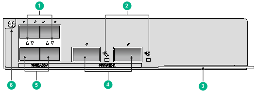
Figure 1 Front panel
|
(1) 1000BASE-X SFP fiber port LEDs |
(2) 40GBASE-R QSFP+ fiber port LEDs |
|
(3) Ejector lever |
(4) 40GBASE-R QSFP+ fiber ports |
|
(5) 1000BASE-X SFP fiber ports |
(6) Captive screw |
Table 1 Module specifications
|
Item |
Specification |
|
Dimensions (H × W × D) |
37.4 × 173.5 × 191.9 mm (1.47 × 6.83 × 7.56 in) |
|
Power consumption |
2 W to 10 W |
|
Net weight |
0.7 kg (1.54 lb) |
|
Hot swapping |
Not supported |
|
Ports |
· 4 × 1000BASE-X SFP fiber ports · 2 × 40GBASE-R QSFP+ fiber ports |
|
Connector type |
· LC · MPO |
|
Ambient temperature |
· Operating: 0°C to 45°C (32°F to 113°F) · Storage: –40°C to +70°C (–40°F to +158°F) |
|
Ambient humidity |
· Operating: 5% RH to 95% RH, noncondensing · Storage: 5% RH to 95% RH, noncondensing |
|
Transmission rate |
· SFP fiber port: 1.25 Gbps · QSFP+ fiber port: 41.25 Gbps |
|
Transmission medium and max transmission distance |
· 1000BASE-X SFP fiber port: see Table 2. · 40GBASE-R QSFP+ fiber port: see Table 3 |
|
Compatible interface switch modules and slots |
· NSQM1MBFEA0 interface switch module (slots 1 and 2) · NSQM2MBFDA0 interface switch module (slots 1 and 2) · NSQM2MBFEA0 interface switch module (slots 1 and 2) |
The 1000BASE-X SFP fiber ports support SFP transceiver modules in Table 2.
Table 2 SFP transceiver modules available for the 1000BASE-X-SFP fiber ports
|
Module |
Central wavelength |
Connector type |
Cable specifications |
Maximum transmission distance |
|
SFP-GE-SX-MM850-A |
850 nm |
LC |
50/125 µm, MMF |
550 m (1804.46 ft) |
|
SFP-GE-LX-SM1310-A |
1310 nm |
LC |
9/125 µm, SMF |
10 km (6.21 miles) |
|
SFP-GE-LH40-SM1310 |
1310 nm |
LC |
9/125 µm, SMF |
40 km (24.85 miles) |
|
SFP-GE-LH40-SM1550 |
1550 nm |
LC |
9/125 µm, SMF |
40 km (24.85 miles) |
|
SFP-GE-LH80-SM1550 |
1550 nm |
LC |
9/125 µm, SMF |
80 km (49.71 miles) |
|
SFP-GE-LH100-SM1550 |
1550 nm |
LC |
9/125 µm, SMF |
100 km (62.14 miles) |
The 40GBASE-R QSFP+ fiber ports support QSFP+ transceiver modules in Table 3.
Table 3 QSFP+ transceiver modules available for the 40GBASE-R QSFP+ fiber ports
|
Module |
Central wavelength |
Connector type |
Cable specifications |
Modal bandwidth |
Maximum transmission distance |
|
QSFP-40G-SR4-MM850 |
850 nm |
MPO |
50/125 µm, MMF |
2000 (MHz*km) |
100 m (328.08 ft) |
|
QSFP-40G-LR4-WDM1300 |
1310 nm |
LC |
9/125 µm, SMF |
N/A |
10 km (6.21 miles) |
|
QSFP-40G-CSR4-MM850 |
850 nm |
MPO |
50/125 µm, MMF |
2000 (MHz*km) |
300 m (984.25 ft) |
4 LEDs
The module provides a LED for each 1000BASE-X SFP port and 40GBASE-R QSFP+ port to indicate their operating status.
Table 4 1000BASE-X SFP port LED description
|
Status |
Description |
|
Flashing |
The port is sending or receiving data. |
|
On |
A link is present on the port. |
|
Off |
No link is present on the port. |
Table 5 40GBASE-R QSFP+ port LED description
|
Status |
Description |
|
Flashing |
The port is sending or receiving data. |
|
On |
A link is present on the port. |
|
Off |
No link is present on the port. |
5 Installing or removing the interface module
|
|
CAUTION: · Wear a reliably-grounded ESD wrist strap or ESD gloves before you install or remove the interface module. · Do not touch the components on the interface module. · The interface module is not hot swappable. You must first power off the device before installing or removing the interface module. |
5.1 Installing the interface module
To install the interface module on the device, you must first install the module on an interface switch module.
To install the interface module:
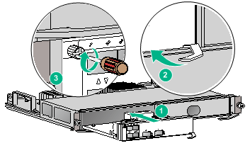
1. Install the interface module on an interface switch module.
a. Place the interface switch module on an antistatic workbench with its PCB components facing up.
If the interface switch module has been installed on the device, first remove it from the device. For the removal procedure, see "Removing the interface module."
b. Remove the filler panel from the target slot on the interface switch module.
c. Insert the interface module slowly into the target slot along the guide rails.
d. Use a Phillips screwdriver to fasten the captive screw on the interface module to secure it in the interface switch module.
Figure 2 Installing the interface module on an interface switch module
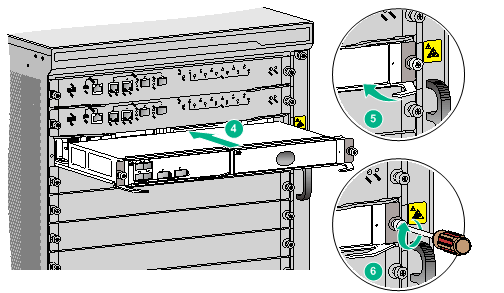
2. Install the interface switch module on the device.
a. Open the ejector levers on the interface switch module and then push the module slowly into the slot along the guide rails.
b. Close the ejector levers to ensure that the module is in close contact with the backplane.
c. Use a Phillips screwdriver to fasten the captive screws on the interface switch module to secure the module in the device.
Figure 3 Installing the interface switch module on the device
5.2 Removing the interface module
To remove the interface module, first remove the interface switch module where the interface module is attached from the device.
To remove the interface module:
1. Remove the interface switch module from the device.
a. Use a Phillips screwdriver to loosen the captive screws on the interface switch module until all pressure is released.
b. Open the ejector levers to disengage the module from the backplane, and then pull the module slowly out of the slot along the guide rails.
2. Remove the interface module from the interface switch module.
a. Use a Phillips screwdriver to loosen the captive screw on the interface module until all pressure is released.
b. Open the ejector lever to disengage the module from the interface switch module, and then pull the module slowly out of the slot along the guide rails.
3. Place the interface module on an anti-static workbench or in an anti-static bag with its PCB components facing up.
4. If you are not to install a new interface module, install a filler panel in the slot to prevent dust and ensure good ventilation.
Copyright © 2019 New H3C Technologies Co., Ltd.
The information in this document is subject to change without notice.
