- Released At: 29-06-2024
- Page Views:
- Downloads:
- Table of Contents
- Related Documents
-
H3C WBC Module Upgrade Guide
Copyright © 2024 New H3C Technologies Co., Ltd. All rights reserved.
No part of this manual may be reproduced or transmitted in any form or by any means without prior written consent of Hangzhou H3C Technologies Co., Ltd.
Except for the trademarks of New H3C Technologies Co., Ltd., any trademarks that may be mentioned in this document are the property of their respective owners.
The information in this document is subject to change without notice.
Contents
Log in to the WBC monitoring platform
Log in through the management port
Log in through the inline service port
Upgrade service components through the WBC monitoring platform
Upgrade the Cloudnet component
Upgrade the device management component
About the Update software package
Restore the backup configuration
Introduction
This document provides guidance on upgrading the H3C WBC module (EWPM1WBCE0ENT). The following upgrade methods are available:
· Service component upgrade through the WBC monitoring platform: Use the Web interface of the WBC monitoring platform to upgrade the Cloudnet platform and device management service component. This method is simple and easy to use. As a best practice, use this method when the target overall system image differs by no more than three versions from the current overall system image.
· ISO image installation: An ISO image is an overall system image for the WBC module. Reinstalling the system through an ISO image clears all configuration information and restores the device to factory settings. Please proceed with caution. Before installing an ISO image, back up the device configuration. As a best practice, use this method when the target overall system image differs by three or more versions from the current overall system image.
|
|
NOTE: Procedures and information in the examples might be slightly different depending on the software or hardware version. |
Log in to the WBC monitoring platform
The device supports logging into the WBC monitoring platform in either of the following ways:
· Log in to the monitoring platform through the management port on the front panel of the module.
· Log in to the monitoring platform through the inline service port of the module.
Log in through the management port
Set up the login environment
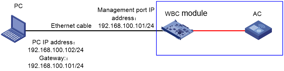
Configure network interconnectivity between the PC and the management port of the WBC module. The following network diagram is for reference only. Configure the IP address according to the actual network environment.
Figure 1 Device login environment
Log in through the management port
1. Connect the PC to the management port of the module through an Ethernet cable, and configure the PC's IP address to be on the same subnet as the management port. Enter https://x.x.x.x:9999 in the browser (where x.x.x.x is the management IP address of the WBC monitoring platform, defaulting to 192.168.100.101).
Figure 2 WBC monitoring platform login page
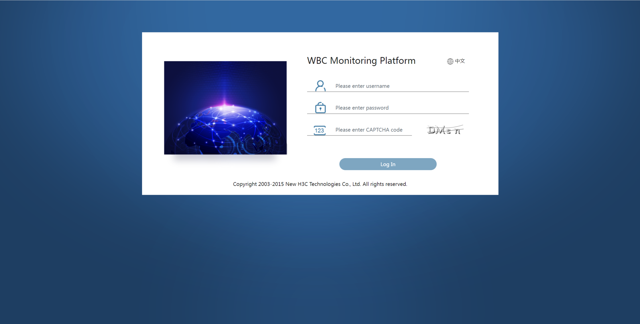
2. Enter the username, password, and CAPTCHA code in the login box, and click Log In. The default username is admin and the default password is admin.Default.0506.
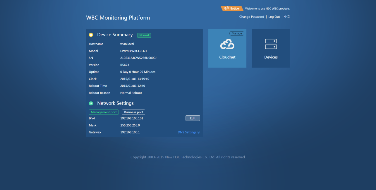
Figure 3 WBC monitoring platform

|
|
NOTE: You can modify the management and service IP addresses of the WBC module based on actual networking conditions. |
Log in through the inline service port
Set up the login environment
Configure network interconnectivity between the PC and the inline service port of the WBC module. The following network diagram is for reference only. Configure the IP address according to the actual network environment.
Figure 4 Device login environment

Log in through the management port
1. Connect a PC to the AC's Layer 2 Ethernet interface using an Ethernet cable, and configure IP addresses for the PC, AC, and WBC module to ensure network communication among them.
|
|
NOTE: When you install a module in SLOT 1 at the AC rear, the corresponding in-line service port on the AC is GE1/0/17. When you install a module in SLOT 2 at the AC rear, the corresponding in-line service port is GE1/0/18. |
2. Enter https://x.x.x.x:9999 in the browser's address bar (where x.x.x.x is the inline service port IP address of the module, defaulting to 172.25.252.18). Then, enter the username and password and click to log in. The default username is admin and the default password is admin.Default.0506.
Figure 5 WBC monitoring platform
Upgrade service components through the WBC monitoring platform
The H3C WBC module uses the H3Linux operating system and primarily contains the following components:
· Cloudnet component: Manage devices, monitor the network online, and maintain devices. To use the most recent Cloudnet features, use the WBCE0ENT_OASIS-XXX.bin software package to update Cloudnet.
· Device management component: Configure network settings for the WBC monitoring platform, update the system, manage backups and restorations, and monitor the device health state and CPU usage in real time. When the monitoring platform, backup restoration, or security features change, use the WBCE0ENT_UPDATE-XXX.bin software package to update the device management component.
Upgrade the Cloudnet component
1. Log in to the WBC monitoring platform.
Figure 6 Log in to the WBC monitoring platform.

2. Click Manage at the top right corner of the Cloudnet tile to enter the Cloudnet O&M interface.
Figure 7 Cloudnet O&M interface
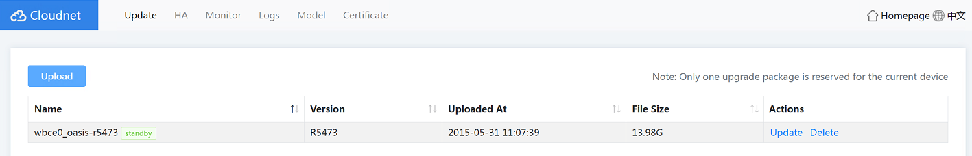
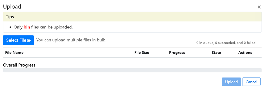
3. (Optional.) Click Upload on the Update tab. In the dialog box that opens, click Select File and browse to the local Cloudnet image file WBCE0ENT_OASIS-XXX.bin, and then click Upload. After the upload process ends, click to close the dialog box. The device supports reserving only one image. To upload a new image, you must first delete the existing one.
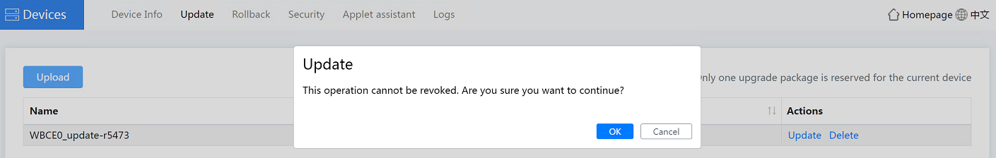
4. Click Update in the Actions column, and then click OK.
Figure 9 Updating Cloudnet

5. Wait for the Cloudnet update to complete, and then click OK.
Upgrade the device management component
About the Update software package
The Update package primarily is used for system updates on the WBC series. As a best practice to use the latest features properly, use the corresponding Update packet to update the system promptly.
Procedure
1. Log in to the WBC monitoring platform.
2. Click the Devices tile to access the device management O&M page, and then click the Update tab.
Figure 10 Device management O&M interface

3. (Optional.) Click Upload on the Update tab. In the dialog box that opens, click Select File and browse to the local system image file WBCE0ENT_UPDATE-XXX.bin, and then click Upload. After the upload process ends, click to close the dialog box. The device supports reserving only one image. To upload a new image, you must first delete the existing one.

4. Click Update in the Actions column, and then click OK.
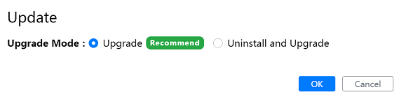
5. Select the upgrade mode, Upgrade or Uninstall and Upgrade, and then click OK.
¡ Uninstall and Upgrade: Uninstall all components included in the software package and then use the software package to perform upgrade.
¡ Upgrade: Upgrade only components with a different version from the software package. The Upgrade method is faster than the Uninstall and Upgrade method. As a best practice, use the Uninstall method. If direct upgrade fails, try using the uninstall and upgrade method. If the uninstall and upgrade method also fails, contact Technical Support.
Figure 13 Selecting the upgrade mode
|
|
NOTE: During the uninstallation and upgrade process, the device will log out and return to the login page. After logging in again, you can see the update progress. Upon completion, the system prompts that the upgrade has succeeded. |
Install an ISO image
Overview
An ISO image is an overall system image for the WBC module. Reinstalling the system through an ISO image clears all configuration information and restores the device to factory settings. Please proceed with caution. Before installing an ISO image, back up the device configuration.
To install an ISO image on a WBC module:
1. As a best practice, back up the configuration.
2. Configure UDS on the local PC.
3. Install the ISO image on the WBC module.
4. Install service components.
5. Restore the backup configuration.
Precautions
· During the ISO image installation process, make sure the network connection remains stable and uninterrupted, and do not close the UDS software. If you do so, the installation might fail and device errors might occur.
· If such issues arise due to a misoperation, power off the WBC module, then power it on and restart the module. Afterward, try to reinstall the ISO image.
· If the network port of the WBC module connects to the UDS software device through a switch, disable the DHCP service on the switch and the related links.
· Do not open TFTP on the PC.
Back up the configuration
1. Log in to the WBC monitoring platform.
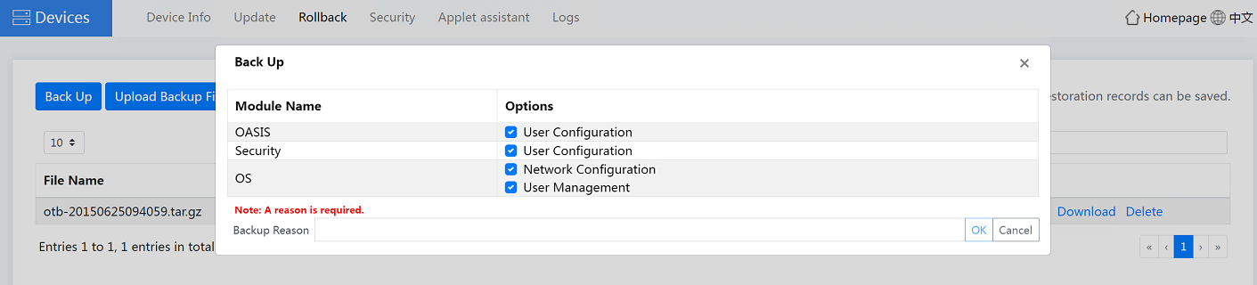
2. Click the Devices tile to access the device management O&M page. Click Back Up on the Rollback tab. Select data to back up based on actual requirements. You can back up data including OASIS, Security, and OS. Enter the backup reason, and then click OK.
Figure 14 Backing up the configuration
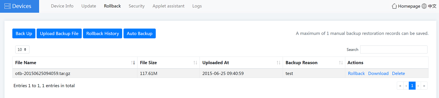
3. Click OK. The configuration backup content is displayed on the page, as shown in Figure 15.
¡ To download the configuration backup file to the local device, click Download.
¡ To restore the configuration in the backup file, click Rollback.
¡ To delete the backup file, click Delete.
Figure 15 Configuration backup completed
|
|
NOTE: To reinstall the system with the previous configuration data retained, be sure to download and save the backup data locally. After the system is successfully reinstalled, upload the backup data to the device. |
Configure UDS
|
|
NOTE: · To obtain the UDS PXE server software, access the H3C official website, navigate to Support > Software Download > Wireless > WBC Series Multiservice Access Controllers. Find the EWPM1WBCE0ENT Multiservice Access Controller item, click to enter and download the most recent UDS software version released with the product. You can install the software on the Windows 7, Windows 8, or Windows 10 operating system. · To run the software, unzip the obtained UDS package, and then double click to run UDS.exe. |
After installing the UDS tool on your local PC, follow these steps to complete the UDS setup:
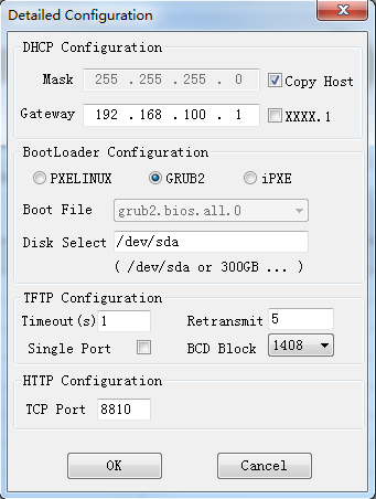
1. Open the UDS software, set the start IP and gateway, and select the ISO image source. Make sure the start IP address is in the same network segment as the PC subnet.
¡ Start IP: Enter the start IP address.
¡ Gateway: Click the ![]() button next to the IP Count field to specify the gateway IP.
As shown in Figure 17,
select GRUB2 for the BootLoader configuration and retain the default
settings for other fields.
button next to the IP Count field to specify the gateway IP.
As shown in Figure 17,
select GRUB2 for the BootLoader configuration and retain the default
settings for other fields.
¡ Source: Select the ISO image on your local PC.
Figure 16 Configuring the start IP address

Figure 17 Specifying the gateway address
2. Click the ![]() icon in the top
left corner to enable the UDS downloading mode.
icon in the top
left corner to enable the UDS downloading mode.

Install the ISO image
1. Connect the serial port and Ethernet cable of the local PC to the serial port and the first GE port on the front panel of the WBC module, respectively. Set the baud rate of the serial port on the PC to 115200. As a best practice, connect the PC and the WBC module directly and avoid using other DHCP servers.
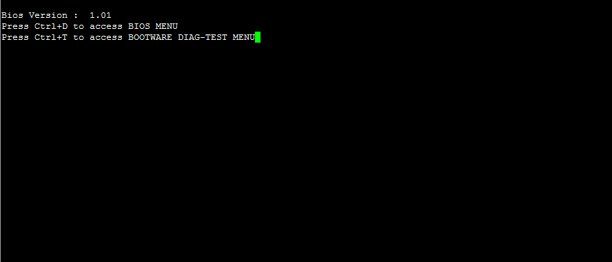
2. After powering on the WBC module, press CTRL+D as prompted to enter BOOT mode.
Figure 19 Powering on the WBC module
3. Select <1> Select Boot Device, and then select EFI Network 1 for IPv4 (connected port on the WBC module) to write the ISO image into the WBC module. Note that EFI Network 1 for IPv4 is not necessarily fixed as the second option. If you use a serial port server, the serial port output might be chaotic due to the server itself.
|
|
NOTE: If the PC network cable is connected to GE0 on the front panel of the WBC module, select EFI Network 0 for IPv4. If the PC network cable is connected to GE1 on the front panel of the WBC module, select EFI Network 1 for IPv4. |
Figure 20 Writing the ISO image

4. When the following information appears, it
indicates the image installation is complete. You can then use the ![]() button
at the upper left corner to disable UDS. The installation process takes about
40 minutes, and upon successful installation, the WBC module will automatically
restart.
button
at the upper left corner to disable UDS. The installation process takes about
40 minutes, and upon successful installation, the WBC module will automatically
restart.
Figure 21 ISO image installation completed

Install service components
1. As shown in Figure 21, enter the username and password to log in to the WBC module. The login username and password are root and [email protected], respectively.
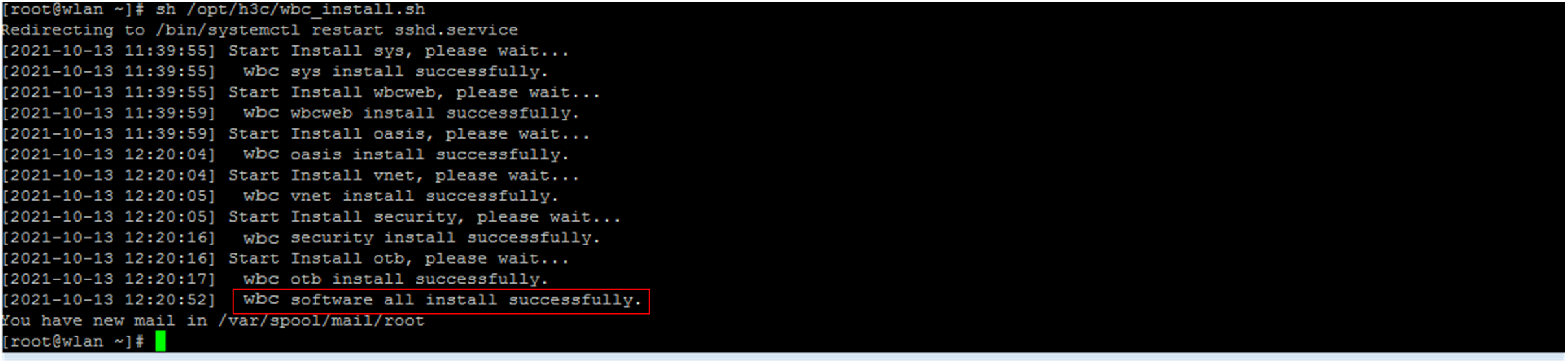
2. After logging into the WBC module, execute the sh /opt/h3c/wbc_install.sh command to install the service components. When the system prompts wbc software all install successfully, it indicates that all service components have been successfully installed. The installation process takes about 40 minutes. Please wait patiently and do not intervene manually during this process.
Figure 22 Installing service components
3. Execute the cat /opt/h3c/version command and verify that all the service components have been installed.
[root@wlan ~]# cat /opt/h3c/version
ISO Version : EWPM1WBCE0ENT-CMW710-R5466P03
ISO Internal Version : H3C EWPM1WBCE0ENT V500R001B64D029SP6603
OASIS Version : R5466P03
BaseBoard CPLD Version : 001
DaughterBoard CPLD Version : 005
SYS Version : V12.2.0
Wbcweb Version : V7.0.0
Vnet Version : V4.0.0
Security Version : V7.3.0
OTB Version : V8.0.0
HA Version : V4.0.0
4. After installation, execute the exit command to exit the system. Additionally, follow these restrictions and guidelines:
¡ Do not edit the root account and password.
¡ Do not directly unplug the WBC module or cut the power. To turn off the WBC module, press and hold the power button on the front panel of the module for 5 seconds until the power LED turns off.
Restore the backup configuration
1. Log in to the WBC monitoring platform.
|
|
NOTE: After using an ISO image to reinstall the system, all configuration information will be cleared, and the device will be restored to factory settings. To log in to the WBC monitoring platform again, use the default IP address. |
2. Click the Devices tile to access the device management O&M page.
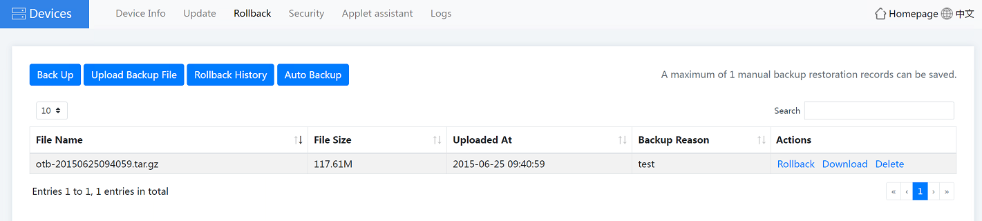
3. You can upload backup files to upload locally saved backup data to the WBC module. As shown in Figure 23, click Upload Backup File on the Rollback tab, select the backup data to upload, and then click Upload.
Figure 23 Uploading a backup file

4. After a successful upload, close the one-click upload page. You can view that the upload file is displayed on the page. Currently, the system supports saving a maximum of one file for restoration. Click Rollback.
Figure 24 Configuration restoration
5. To view or delete the restoration record, click Restoration History on the Rollback tab.
