| Title | Size | Downloads |
|---|---|---|
| H3C ANT-2510P-M4 Patch Antenna Installation Guide-6W100-book.pdf | 1.82 MB |
- Table of Contents
- Related Documents
-
| Title | Size | Download |
|---|---|---|
| book | 1.82 MB |
H3C ANT-2510P-M4 patch antenna installation guide
Installation accessories and tools
Mounting the antenna on a pole
Installing the lightning arrester
H3C ANT-2510P-M4 patch antenna installation guide
Technical specifications
The ANT-2510P-M4 dual-band directional antenna is designed for use in outdoor environments. It is connected to the device through type N male connectors.
Figure 1 Antenna view
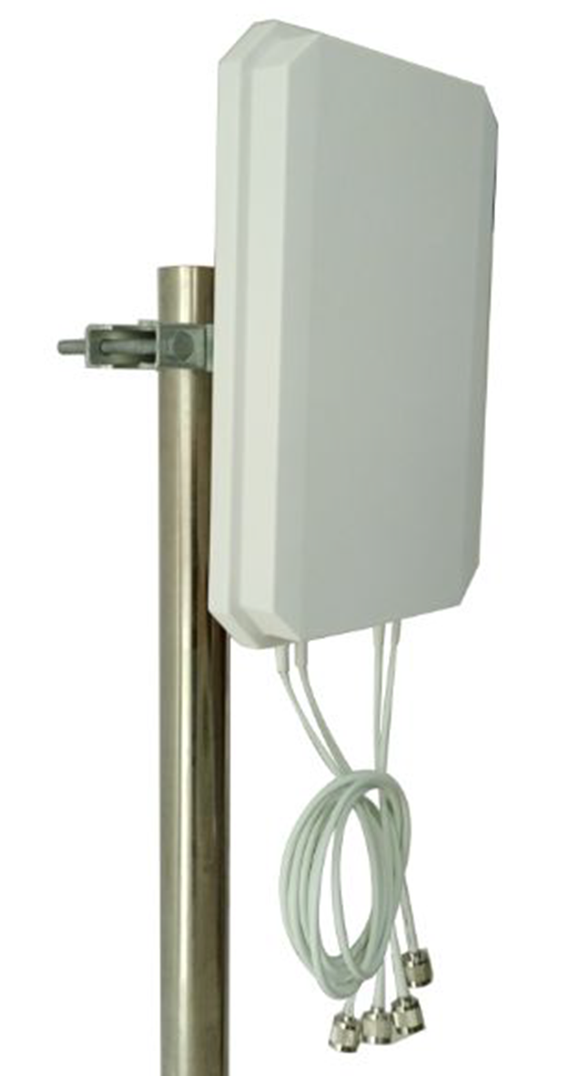
Table 1 Technical specifications
|
Item |
ANT-2510P-M4 |
|
Frequency range |
2400 MHz to 2500 MHz/4900 MHz to 5950 MHz |
|
Polarization type |
Horizontal/vertical |
|
Gain |
10/10 dBi |
|
Horizontal beamwidth (HBW) |
40/40 degrees |
|
Vertical beamwidth (VBW) |
40/40 degrees |
|
Typical front and back ratio (FBR) |
≥ 20/25 dB |
|
Isolation (ISO) |
≥ 24 dB |
|
Impedance |
50 Ω |
|
Voltage standing wave ratio (VSWR) |
≤ 2.0 |
|
Maximum power |
20 W |
|
Connector |
4 × type N male connectors |
|
Cable length |
0.9 m (2.95 ft) |
|
Connector position |
Bottom |
|
Dimensions (H × W × D) |
340 × 200 × 45 mm (13.39 × 7.87 × 1.77 in) |
|
Antenna weight |
1.1 kg (2.43 lb) |
|
Bracket weight |
1.05 kg (2.31 lb) |
|
Antenna color |
White |
|
Application scenario |
Outdoor |
|
Operating temperature |
–40°C to +70°C (–40°F to +158°F) |
|
Storage temperature |
–50°C to +85°C (–58°F to +185°F) |
|
Wind resistance |
35 m/s (114.83 ft/s) |
|
Installation method |
Mounted on a pole with a diameter of 50 to 85 mm (1.97 to 3.35 in). |
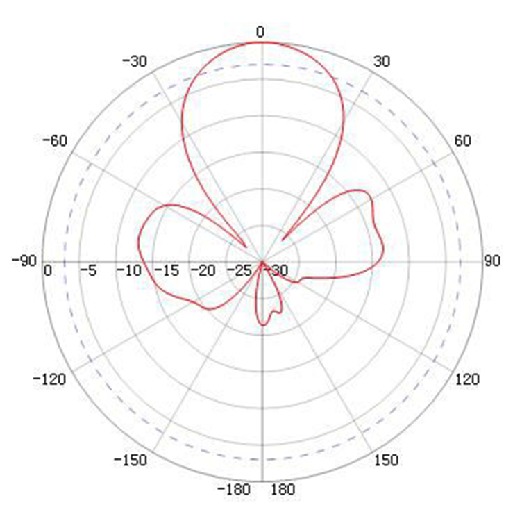
Figure 2 and Figure 3 show the horizontal and vertical radiation patterns.
Figure 2 Typical horizontal pattern
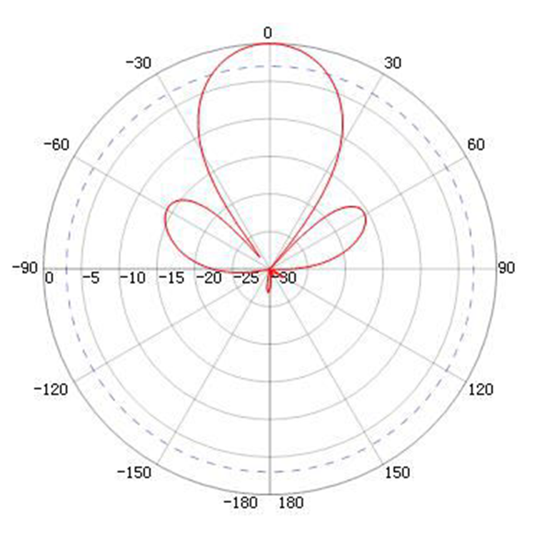
Figure 3 Typical vertical pattern
Safety precautions
|
|
WARNING! · Installing antennas carries some level of risk. For your safety, read the following safety precautions carefully before your operation. · Keep the antenna away from power sources, street lamps, power distribution boxes, or other places that might cause electrical shock. · Do not touch any power lines for your safety. |
· Keep safety in mind when you select your installation site. Keep away from electric power lines and other lines.
· Do not work alone when you install the antenna.
· If you need to raise a pole, work with other people to avoid bodily injury.
· Do not use a metal ladder. Do not work on a wet or windy day. Dress properly, for example, shoes with rubber soles. Wear rubber gloves.
· If the antenna, antenna cable, or any other installation accessory drops, get away from it to avoid bodily injury.
· To avoid any potential hazards, always have a professional handle power connection rather than attempting it yourself.
· If an accident, for example, electrical shock, occurs, immediately call for qualified emergency help.
Installation guidelines
To ensure optimal performance of the antenna, follow these guidelines:
· Install the antenna vertically with the connector side facing downwards.
· Keep the antenna away from metal obstacles, such as heating pipes and air conditioners.
· The material and thickness of walls determine the number of walls that the RF signal can penetrate. 5 GHz signal attenuation is large. Avoid signal penetration through solid walls.
Choosing a mounting location
To ensure optimal coverage, follow these guidelines when choosing a mounting location for the antenna:
· Perform site surveys to determine the antenna mounting location and height. Make sure no obstruction, especially no solid walls and metal plates, exists between the antenna and the target coverage area.
· The antenna installation location must be as close as possible to the AP to reduce the antenna cable length and signal loss.
· The AP must be installed at a location where wires (cables or fibers) and power (local power supply or PoE) can reach.
Mounting the antenna
You can mount the ANT-2510P-M4 antenna on a pole. The installation accessories are provided (installation tools are user supplied). If you intend to install your antenna in a way other than what is described in this document, you must provide the appropriate installation accessories.
Installation accessories and tools
· Installation accessories provided with the antenna:
¡ One articulating arm.
¡ One mount plate.
¡ Two pole-mount clamps.
¡ One mount arm.
¡ One label.
· User-supplied installation tools:
¡ One adjustable wrench.
¡ One pole with a diameter of 50 to 85 mm (1.97 to 3.35 in).
Mounting the antenna on a pole
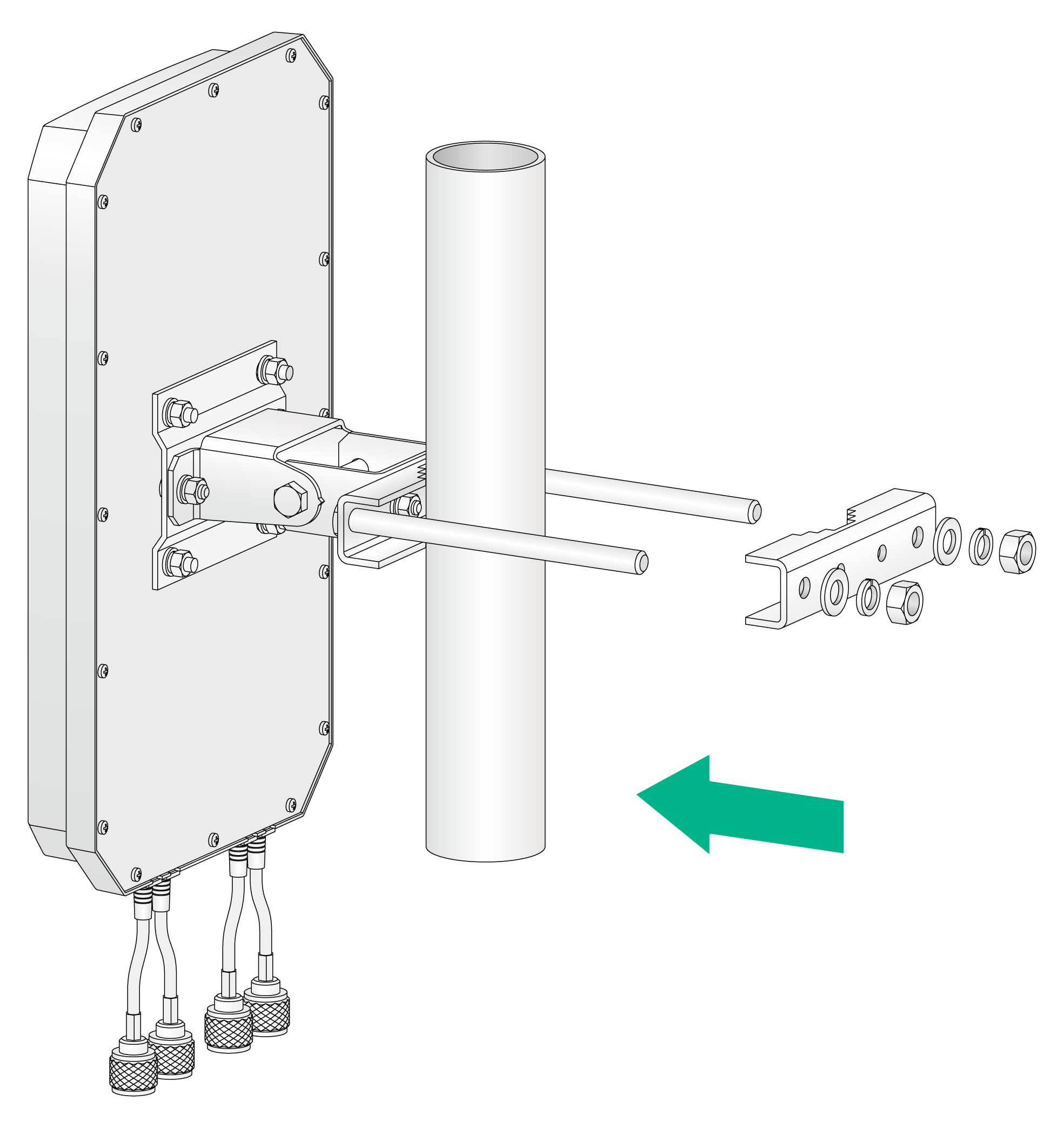
1. Use a wrench to remove a pole-mount clamp and nuts.
Figure 4 Removing a pole-mount clamp and nuts
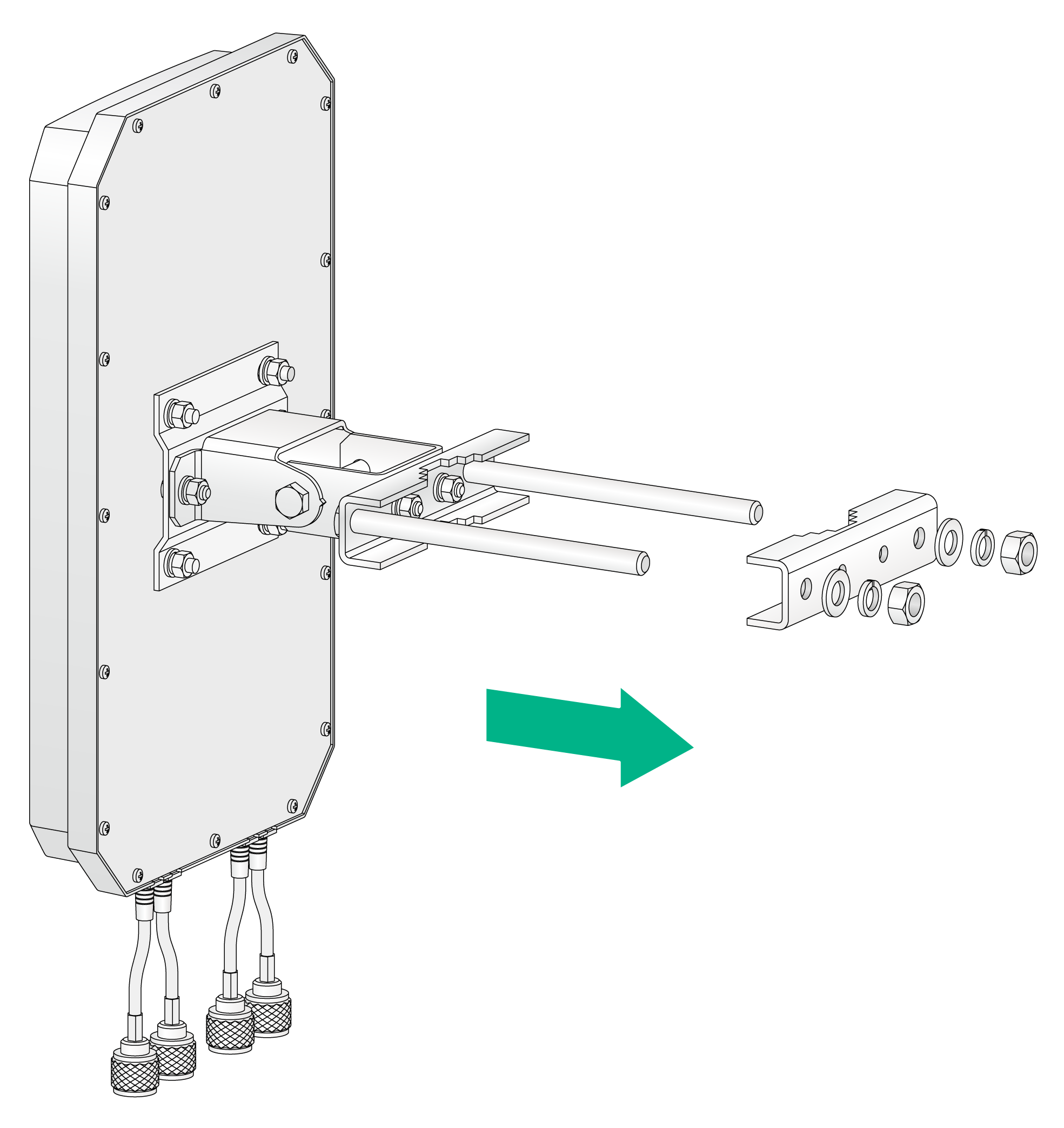
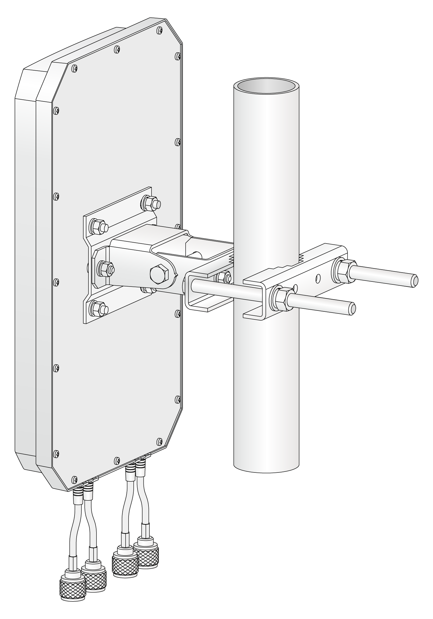
2. Mount the antenna on a pole, and then fasten the pole-mount clamp nuts.
Figure 5 Mounting the antenna on a pole
3. Adjust the vertical orientation of the antenna, and then fasten the articulating arm nuts.
Figure 6 Adjusting the vertical orientation of the antenna
Installing the lightning arrester
No lightning arrester is provided with the antenna. Purchase one yourself.
The antenna is mounted outdoors. You must install a lightning arrester for it. To install a lightning arrester, install it on the AP or on an outdoor antenna connector, connect an antenna cable to it, and then ground it. Make sure the grounding terminals are grounded reliably.
Recommended cable
The ANT-2510P-M4 antenna has four antenna connectors. It is connected to a 2.4 GHz or 5 GHz antenna port on an H3C outdoor AP through a type N connector. As a best practice, use a high-quality and low-loss cable with the antenna. A coaxial cable loses efficiency as the frequency increases, causing signal loss. Keep the cable as short as possible because cable length also causes signal loss (the longer the run, the greater the loss).
