- Released At: 11-08-2023
- Page Views:
- Downloads:
- Table of Contents
- Related Documents
-
Contents
H3C ANT-2503C-S4 ceiling-mount antenna installation guide
Mounting the antenna on a ceiling
H3C ANT-2503C-S4 ceiling-mount antenna installation guide
Technical specifications
The ANT-2503C-S4 antenna is designed for use in indoor environments. It is connected to 2.4 GHz or 5 GHz antenna ports on an H3C indoor AP through RP-SMA connectors.
Figure 1 Antenna view
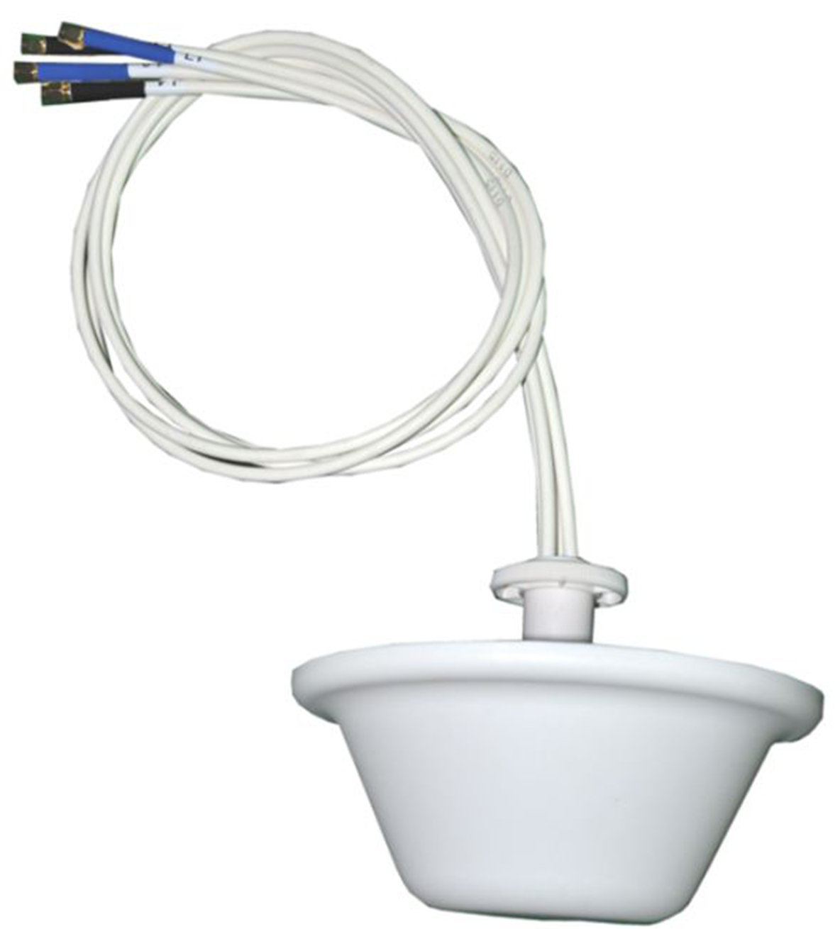
Table 1 Technical specifications
|
Antenna type |
ANT-2503C-S4 |
|
|
Operating frequency range |
2400 MHz to 2500 MHz |
5150 MHz to 5850 MHz |
|
Bandwidth |
100 MHz |
700 MHz |
|
Peak gain |
3 dBi |
5 dBi |
|
Horizontal beamwidth |
360 degrees |
|
|
Voltage standing wave ratio (VSWR) |
≤ 2.0 |
|
|
Impedance |
50 Ω |
|
|
Polarization type |
Vertical |
|
|
Max. power |
20 W |
|
|
Connector |
4 × RP-SMA male |
|
|
Dimensions |
(φ173 × 72.5) ± 1.5 mm/(6.81 × 2.85) ± 0.06 in |
|
|
Weight |
0.38 ± 0.1 kg (0.84 ± 0.22 lb) |
|
|
Operating temperature |
–40°C to +60°C (–40°F to +140°F) |
|
|
Installation |
Ceiling mounting |
|
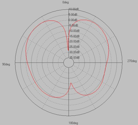
Figure 2 through Figure 5 show the horizontal and vertical radiation patterns.
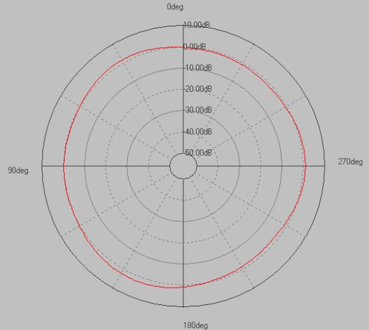
Figure 3 Vertical pattern
Safety precautions
|
|
WARNING! · Installing antennas carries some level of risk. For your safety, read the following safety precautions carefully before your operation. · Keep the antenna away from power sources, street lamps, power distribution boxes, or other places that might cause electrical shock. · Do not touch any power lines for your safety. |
· Keep safety in mind when you select your installation site. Keep away from electric power lines and other lines.
· Do not work alone when you install the antenna.
· To avoid any potential hazards, always have a professional handle power connection rather than attempting it yourself.
· If an accident, for example, electrical shock, occurs, immediately call for qualified emergency help.
Installation guidelines
The ANT-2503C-S4 is designed to be mounted indoors on a ceiling to maximize its omnidirectional propagation.
Install multiple antennas where necessary because doors, windows, and walls degrade signal quality.
Keep the antenna away from metal obstructions and wire mesh.
Choosing a mounting location
The ANT-2503C-S4 is typically mounted indoors on the ceiling. Keep the antenna away from obstacles and metallic objects such as heating and air-conditioning ducts, large ceiling trusses, and primary power transmission systems.
Typically, the higher an antenna is above the ground, the larger the signal coverage area.
If possible, use a cable as short as possible to connect the antenna and AP.
Mounting the antenna
You can mount the ANT-2503C-S4 antenna on a ceiling. The installation accessories are provided with the antenna (installation tools are user supplied). If you intend to mount your antenna in a way other than what is described in this document, you must provide the installation accessories yourself.
Installation tools
The following tools are required for installing the antenna
· One electric drill and drill bits
· One adjustable wrench
Mounting the antenna on a ceiling
1. Drill a 25 mm (0.98 in) diameter hole in the ceiling where you want to mount the antenna.
2. Remove the flat washer from the antenna and place it above the ceiling.
3. Thread the antenna cable through the hole you drilled in step 1 until the base of the antenna is flush with the ceiling.
4. From above the ceiling, thread the antenna cable through the opening on the split flat washer..
5. Fasten the split flat washer onto the antenna’s thread.
6. Connect the antenna connectors to the antenna ports on the AP based on the color of the heat-shrink tube on the connector. If the heat-shrink tube is black, the antenna connector is designed for use with 2.4 GHz signals. If the heat-shrink tube is blue, the antenna connector is designed for use with 5 GHz signals.
Figure 4 Mounting the antenna to a ceiling
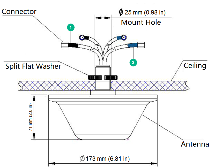
|
(1) Cable (black, 2.4 GHz) |
(2) Cable (blue, 5 GHz) |
