- Table of Contents
- Related Documents
-
01-Text
Download Book (4.04 MB)Examining the installation site· 1
Installation site selection· 1
Temperature and humidity requirements· 1
Grounding and lightning protection· 1
Installation tools and equipment 3
Connecting the grounding cable· 6
Attaching the AP bracket to the AP· 8
Connecting the AP to a PoE injector and the network· 13
Verifying the installation· 15
Verifying the network connection· 17
Appendix A Technical specifications· 18
Optional transceiver modules· 21
Transceiver module, fiber connector, and optical fiber views· 21
Transceiver module specifications· 21
Appendix C Antenna radiation patterns· 24
Preparing for installation
| WARNING! Install the AP under the guidance of technical engineers and read this chapter before installation. |
Examining the installation site
The AP is used for outdoor installation. Before installation, examine the installation site to ensure that the AP will work in a good environment.
Installation site selection
The installation site must be selected according to the network planning and technical requirements of telecommunications equipment, with factors such as climate, hydrology, geology, earthquake, electric power, and transportation taken into consideration.
The location for installing the AP must meet the following requirements:
· Not exposed to high temperature, dust, harmful gases, electromagnetic interference sources (high powe radars, radio stations, or electrical substations), unstable voltage, heavy vibration, and loud noise.
· Dry, without any leakage, dripping, or dew.
· Away from inflammable and explosive substances.
· More than 5 m (16.40 ft) away from 3G and 4G base stations and antennas.
Temperature and humidity requirements
Table 1 Temperature and humidity requirements
Specification | |
Operating temperature | –30°C to +55°C (–22°F to +131°F) |
Storage temperature | –40°C to +85°C (–40°F to +185°F) |
Operating humidity | 0% RH to 100% RH, non-condensing |
Storage humidity | 0% RH to 100% RH, non-condensing |
Power supply
The AP uses a power injector for power input. No power injector is provided with the AP. You can order an H3C PoE power injector to power the AP. See "Connecting the AP to a PoE injector and the network" for the connection method.
Grounding and lightning protection
The AP must be reliably grounded. Make sure the grounding points of the grounding conductor of the AP, lightning arrestors, PE wire of the power cord, and antenna support are separate from each other, make good contact, and are securely connected and treated with corrosion protection.
Ground resistance
· The ground resistance is usually required to be less than 5 ohms, and less than 10 ohms in an area with less than 20 thunderstorm days a year. If a piece of angle steel is buried as the grounding conductor, the ground resistance is required to be less than 10 ohms. In an area with a higher ground resistance, reduce the ground resistance by using brine or resistance reducing agent around the grounding conductor.
· The top of the grounding conductor must be a minimum of 0.7 m (2.30 ft) away from the ground surface. In cold areas, the grounding conductor must be buried below the frozen soil layer.
Grounding conductor
· If a grounding strip is available, connect the yellow and green grounding cable of the AP to the grounding strip. To make a grounding cable, make sure the cable has a cross-section area of a minimum of 6 mm2 (0.01 in2) and a length of no longer than 3 m (9.84 ft).
· If no grounding strip is available, bury a piece of angle steel/steel tube a minimum of 0.5 m (1.64 ft) long in the earth to act as the grounding conductor. It must be zinc-plated.
¡ In the case of a piece of angle steel, the size must be a minimum of 50 × 50 × 5 mm (1.97. × 1.97 × 0.20 in).
¡ In the case of a piece of steel tube, it must have a wall thickness of a minimum of 3.5 mm (0.14 in). Weld the yellow and green grounding cable of the AP onto the grounding conductor and use anti-erosion treatment on the welding joint. With a cross-section area of a minimum of 6 mm2 (0.01 in2), the grounding cable must be as short as possible and must not be coiled.
· Make sure the grounding terminals of all the lightning arresters of the AP and the peer device of the AP are reliably grounded.
Ground lead
A ground lead is a metal conductor connecting a grounding net and a grounding strip. The grounding cable of the AP must be connected to the grounding strip. The ground lead must be 30 m (98.43 ft) or shorter. A piece of zinc-coated flat steel with a cross-section area of 40 × 4 mm (1.57 × 0.16 in) or 50 × 5 mm (1.97 × 0.20 in) is recommended. Connect the grounding strip and the ground lead of the AP through the yellow and green grounding cable with an area of 35 mm2 (0.05 in2), or weld them directly. Use anti-erosion treatment on the welding joint.
Power grounding (AC)
· Use a power cord with a protective earth (PE). Do not use a power cord with only an L line and an N line.
· The neutral line of the power cord must not be connected with the PGND of other communications equipment. The L and N lines cannot be connected.
Lightning rod
· The lightning protection grounding (for example, the grounding of the lightning rod) must be connected to the grounding conductor of the equipment room.
· The lightning rod must be tall enough to protect the AP and its antennas.
· In plain areas, the shielding angle of the lightning rod must be less than 45 degrees. In mountainous areas or lightning areas, the shielding angle must be less than 30 degrees.
Ethernet cable
· Use a shielded twisted pair cable for outdoor installation. Make sure the devices at the two ends of the cable are reliably grounded.
· If a metal tube is used, make sure the Ethernet cable is reliably grounded at both ends of the tube.
Installation accessories
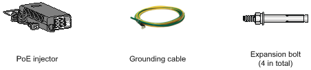
Figure 1 lists the installation accessories provided with the AP. Figure 2 lists the installation accessories to be prepared by users.
Figure 1 Installation accessories provided with the AP
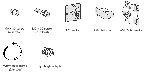
Figure 2 Installation accessories to be prepared by users
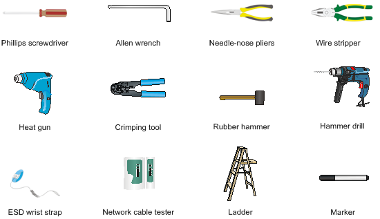
Installation tools and equipment
When installing the AP, you might need the following tools. Prepare these tools and equipment yourself as required.
Figure 3 Installation tools and equipment
Installing the AP
IMPORTANT: To ensure radio coverage, have the AP installed by technical personnel as a best practice. |
When you install the AP, follow these restrictions and guidelines:
· The AP is large and heavy. Avoid bodily injury and device damage during the installation.
· If you install the AP on a pole, make sure the pole is vertical to the ground and iron components have been treated with corrosion protection.
· If you pole-mount the AP on the top of a building, make sure the AP does not project beyond the sides of the building.
· To avoid high temperature caused by exposure to the sun, install the AP in a place without or with less direct sunlight and take protection measures if necessary.
Pre-installation tasks
Before installing an AP, perform the following tasks:
· Connect the AP to the power source and the network. Examine the LED to verify that the AP can operate correctly. For more information about the AP LED, see "Appendix B LEDs and ports."
· Verify that cabling at the installation site has been completed.
· Record the AP MAC address and serial number marked on the rear of the AP for future use.
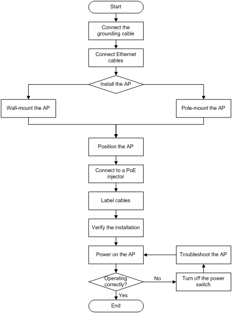
Installation flowchart
Figure 4 Installation flowchart
Connecting the grounding cable
| CAUTION: · Correctly connecting the grounding cable is crucial to lightning protection and EMI protection. · Before connecting the AP to a power injector, make sure the AP has been reliably grounded using the grounding cable. |
The AP is not provided with a grounding cable. Prepare one yourself.
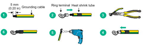
To connect the grounding cable to the AP:
1. Attach the ring terminal to the grounding cable.
Figure 5 Attaching the ring terminal to the grounding cable
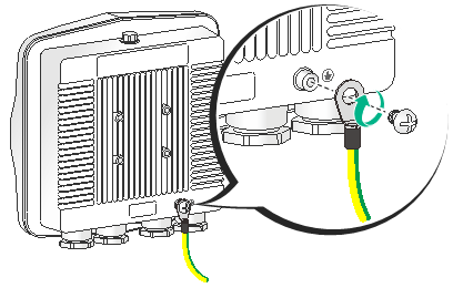
2. Attach the ring terminal of the grounding cable to the grounding screw on the AP. Connect the other end of the grounding cable to the earth.
Figure 6 Attaching the grounding cable to the AP
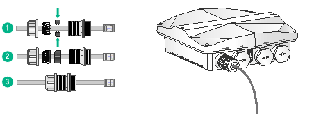
Connecting Ethernet cables
| IMPORTANT: Only CAT5e and above Ethernet cables can be used. As a best practice, use shielded twisted pair (STP) cables. |
To connect an Ethernet cable:
1. Disassemble the liquid-tight adapter and detach the rubber split sealing washer.
2. Feed the Ethernet cable through the liquid-tight adapter and attach the split sealing washer.
3. Connect the Ethernet cable to the target port on the AP.
4. Fasten the liquid-tight adapter and sealing nut.
Figure 7 Connecting an Ethernet cable to the AP
Installing the AP
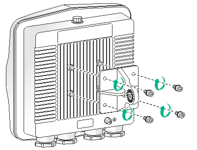
Attaching the AP bracket to the AP
| CAUTION: Keep the protective vent port closed on the AP. Do not open it. |
Before mounting the AP on a wall or pole, attach the AP bracket to it.
To attach the AP bracket to the AP:
1. Align the mounting holes in the AP bracket with the screw holes in the rear of the AP. Use M5 screws to attach the AP bracket to the AP.
Figure 8 Attaching the AP bracket to the AP
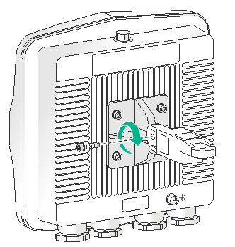
2. Use an M6 screw to attach the articulating arm to the AP bracket.
Figure 9 Attaching the articulating arm to the AP bracket
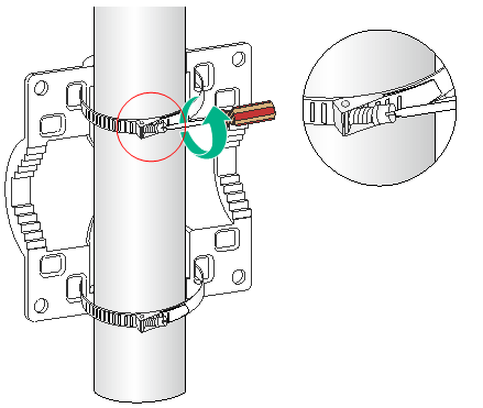
Pole-mounting the AP
Worm-gear clamps and a wall/pole bracket are required to pole-mount the AP. The worm-gear clamp provided with the AP is applicable to poles with a diameter of 65 to 90 mm (2.56 to 3.54 in). If the diameter of the pole is not in the range, prepare worm-gear clamps yourself.
You can mount the AP on a vertical or horizontal pole.
Mounting the AP on a vertical pole
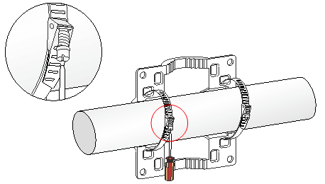
1. Pass the worm-gear clamps through the mounting holes in the wall/pole bracket. Use the worm-gear clamps to secure the wall/pole bracket to the vertical pole and fasten the nuts.
Figure 10 Securing the wall/pole bracket to the pole
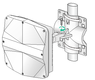
2. Use an M6 screw to secure the articulating arm (attached to the AP) to the wall/pole bracket.
Figure 11 Securing the AP to the wall/pole bracket
Mounting the AP on a horizontal pole
1. Pass the worm-gear clamps through the mounting holes in the wall/pole bracket. Use the worm-gear clamps to secure the wall/pole bracket to the horizontal pole and fasten the nuts.
Figure 12 Securing the wall/pole bracket to the pole
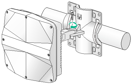
2. Use an M6 screw to secure the articulating arm (attached to the AP) to the wall/pole bracket.
Figure 13 Securing the AP to the wall/pole bracket
Wall-mounting the AP
No expansion bolts are provided with the AP. Prepare them yourself.
To wall-mount the AP:
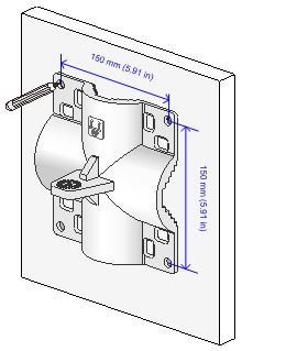
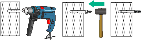
1. Use the AP bracket as a template to mark installation hole locations on the wall.
Figure 14 Marking installation hole locations on the wall
2. Drill holes with a diameter of 8 mm (0.32 in) at the marked locations, as shown in Figure 15.
When you drill holes, follow these restrictions and guidelines:
¡ Hold the drill handle with both hands, with the bit vertical to the wall surface, and prevent wall damage or tilted holes.
¡ If the wall surface is too solid and slippery to locate the bit, punch a notch first.
¡ Each hole must have the same depth.
3. Hammer expansion bolts into the holes and remove the nut and washers from each bolt. Do not hammer the expansion bolts all the way into the wall and leave some space for hanging the AP.
Figure 15 Installing expansion bolts
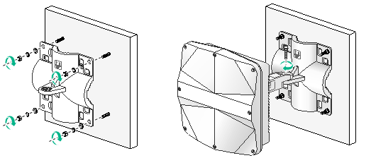
4. Hang the AP on the expansion holes and fasten the screws to secure the wall/pole bracket to the wall, as shown in Figure 16.
5. Use an M6 screw to secure the articulating arm (attached to the AP) to the wall/pole bracket.
Figure 16 Securing the AP to the wall
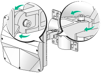
Positioning the AP
The WA530X uses built-in antennas. After the AP installation, you can position the AP as required based on the antenna radiation patterns as shown in "Appendix C Antenna radiation patternsAppendix C Antenna radiation patterns"
To adjust the AP to the desired elevation angle, loosen the screw that attaches the articulating arm to the AP bracket. To adjust the AP to the desired azimuth angle, loosen the screw that attaches the articulating arm to the wall/pole bracket.
Figure 17 Adjusting the AP
Connecting the AP to a PoE injector and the network
| CAUTION: Make sure the installation of the AP is complete before powering on the AP. |
| CAUTION: · Place the PoE injector stable indoors in a well ventilated location. · If multiple PoE injectors are installed in one equipment room or maintenance hole, use one power strip for all these injectors and lead in the power strip from the air switch of the AC power distribution box. |
The PoE1 port on the dual-port H3C PoE injector must be connected to the uplink network through the LAN1 port, and PoE2 through LAN2. The following procedures use the PoE1 port as an example to connect the AP.
Connecting the AP to a PoE injector and to the network through the Ethernet copper port
1. Connect the power cord of the injector to an AC power source.
2. Connect the PoE1 port on the injector to the GE1 port on the AP.
3. Connect the LAN1 port on the injector to a switch or access controller.
Figure 18 Connecting the AP to a PoE injector and to the network through the Ethernet copper port
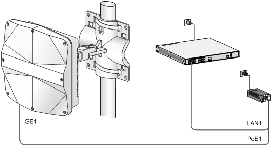
Table 2 Dual-port H3C PoE injector description
Item | Specifications |
Model | ADP060-55V-PoE-GL |
Input | 100 V – 240 V @ 1.5 A |
Output | 55 V @ 1100 mA |
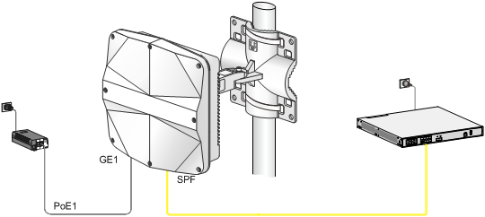
Connecting the AP to a PoE injector and to the network through the fiber port
1. Connect the SFP port on the AP to an Ethernet switch or access controller.
Figure 19 Connecting an optical fiber to the SFP port on the AP
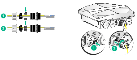
2. Connect the power cord of the injector to an AC power source.
3. Connect the PoE1 port on the injector to the GE1 port on the AP.
Figure 20 Connecting the AP to a PoE injector and the network through the fiber port
Labeling cables
After cable connection, attach labels to each cable as a best practice for future maintenance.
· Attach a label to both ends of a cable and every certain distance.
· Use cable flags or cable sleeves to label antenna and Ethernet cables. Use cable flags to label fiber cables.
· Use waterproof labels with clear content. Attach labels to proper places where they can be seen directly.
· Use transparent waterproof tape to seal outdoor labels.
Verifying the installation
After the installation is complete, check the following items before powering on the AP:
· The power source meets the power specification of the AP.
· The AP is reliably grounded.
· The Ethernet cables are correctly connected.
· The cables are correctly labeled.
· The unused ports on the AP are sealed with waterproof plugs.
Powering on the AP
| IMPORTANT: Make sure all cables are correctly connected and the AP is connected to a PoE power injector correctly before powering on the AP. |
Switch on the external power source and verify that the AP is operating correctly by examining the LED on the AP. For more information about the LED, see "Appendix B LEDs and ports."
Verifying the network connection
All settings of the AP (in fit mode) are configured on the AC. Use the display wlan ap all command on the AC that connects to the AP. If the AP status is R/M, the AP has been connected to the network.
Total number of APs: 1
Total number of connected APs: 1
Total number of connected manual APs: 1
Total number of connected auto APs: 0
Total number of connected common APs: 1
Total number of connected WTUs: 0
Total number of inside APs: 0
Maximum supported APs: 3072
Remaining APs: 3071
Total AP licenses: 128
Local AP licenses: 128
Server AP licenses: 0
Remaining local AP licenses: 127
Sync AP licenses: 0
AP information
State : I = Idle, J = Join, JA = JoinAck, IL = ImageLoad
C = Config, DC = DataCheck, R = Run M = Master, B = Backup
AP name APID State Model Serial ID
ap1 1 R/M WA530X 219801A1NP8182E00001
Appendix A Technical specifications
Table 3 Technical specifications
Item | WA530X |
Dimensions (H × W × D) | 79.5 × 250 × 250 mm (3.13 × 9.84 × 9.84 in) |
Weight | 1.8 kg (3.97 lb) |
Power consumption | 6 W to 25.5 W |
Input | +48~+57 VDC |
Antenna | Built-in directional antennas: · 2.4 G antenna: 10.10 dBi peak gain · 5 G antenna: 8.60 dBi peak gain |
Protocol compliance | IEEE802.11a/b/g/n/ac Wave 2 |
Materials | Water-proof aluminum + plastic housing |
Appendix B LEDs and ports
LEDs
LED | Status | Description | |
| N/A | Off | No power is present. |
Yellow | Flashing at 1 Hz | No radios have been detected. | |
Flashing at 2 Hz | The Ethernet interfaces have not started up and no mesh links are established. | ||
Steady on | The AP is initializing. | ||
Green | Flashing at 0.5 Hz) | The AP is starting up. | |
Flashing at 1 Hz | Only the 2.4G radio has associated clients. | ||
Flashing at 2 Hz | The AP is upgrading the image. | ||
Steady on | The AP has registered on an AC, but does not have any associated clients. | ||
Blue | Flashing at 1 Hz | Only the 5G radio has associated clients. | |
Alternating between green and yellow at 1 Hz | Both the 2.4G and 5G radios have associated clients. | ||
Ports
Figure 21 Ports on the AP
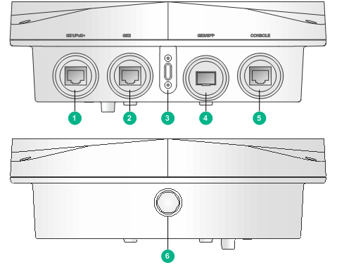
(1) 10/100/1000M Ethernet port (GE1/PoE+) | (2) 10/100/1000M Ethernet port (GE2) |
(3) LED | (4) 1000BASE-X SFP port (GE3/SFP) |
(5) Console port (CONSOLE) | (6) Protective vent port |
Table 5 Port description
Port | Standards and protocols | Description |
10/100/1000M Ethernet port (GE1/PoE+) | · IEEE802.3 · IEEE802.3u · IEEE802.3af · IEEE802.3at | Acts as an uplink interface of the AP to connect to the Internet or MAN. It also supports PoE power input. It is represented by interface number GE1/0/1. |
10/100/1000M Ethernet port (GE2) | · IEEE802.3 · IEEE802.3u | Acts as a interface to connect thet the downlink. It is represented by interface number GE1/0/2. |
1000BASE-X SFP port (GE3/SFP) | · IEEE802.3 · SFP MSA · SFF-8472 | Acts as an uplink interface of the AP to connect to the Internet or MAN. It is represented by interface number GE1/0/3. |
Console port (CONSOLE) | RS/EIA-232 | Used by maintenance personnel for device configuration and management. |
Optional transceiver modules
Transceiver module, fiber connector, and optical fiber views
To connect an SFP fiber port, use an SFP transceiver module and an optical fiber with LC connectors.
Figure 22 SFP transceiver module
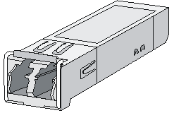
Figure 23 Optical fiber with LC connectors
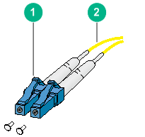
(1) LC connector | (2) Optical fiber |
Transceiver module specifications
The transceiver modules that have MM and SM in their names support multi-mode optical fibers and single-mode optical fibers, respectively.
Table 6 SFP-GE-SX-MM850-A specifications
Item | Specification |
Central wavelength | 850 nm |
Max transmission distance | 550 m (1804.46 ft) |
Data rate | 1250 Mbps |
Connector type | Duplex LC |
Fiber mode | MMF |
Fiber diameter | 50 µm |
Transmit power | –9.5 to 0 dBm |
Receive sensitivity | ≤ –17 dBm |
Saturation | ≤ –3 dBm |
Table 7 SFP-GE-LX-SM1310-A specifications
Item | Specification |
Central wavelength | 1310 nm |
Max transmission distance | 10 km (6.21 miles) |
Data rate | 1250 Mbps |
Connector type | Duplex LC |
Fiber mode | SMF |
Fiber diameter | 9 µm |
Transmit power | –9.5 to –3 dBm |
Receive sensitivity | ≤ –20 dBm |
Saturation | ≤ –3 dBm |
Table 8 SFP-GE-LH40-SM1310 specifications
Item | Specification |
Central wavelength | 1310 nm |
Max transmission distance | 40 km (24.86 miles) |
Data rate | 1250 Mbps |
Connector type | Duplex LC |
Fiber mode | SMF |
Fiber diameter | 9 µm |
Transmit power | –2 to +5 dBm |
Receive sensitivity | ≤ –22 dBm |
Saturation | ≤ –3 dBm |
Table 9 SFP-GE-LH40-SM1550 specifications
Item | Specification |
Central wavelength | 1550 nm |
Max transmission distance | 40 km (24.86 miles) |
Data rate | 1250 Mbps |
Connector type | Duplex LC |
Fiber mode | SMF |
Fiber diameter | 9 µm |
Transmit power | –4 to +1 dBm |
Receive sensitivity | ≤ –21 dBm |
Saturation | ≤ –3 dBm |
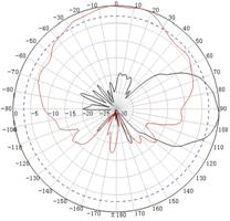
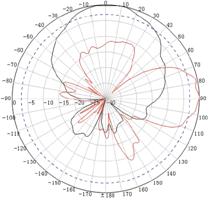
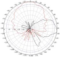
Appendix C Antenna radiation patterns
Table 10 2.4 GHz antenna radiation patterns of the WA530X AP
Central frequency | Antenna radiation patterns | |
Vertical plane | Horizontal plane | |
2400 MHz |
|
|
2450 MHz |
|
|
2500 MHz |
|
|
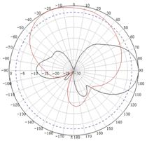
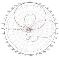
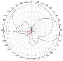
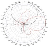
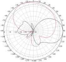
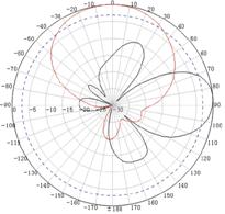
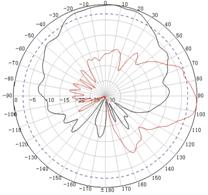
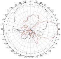
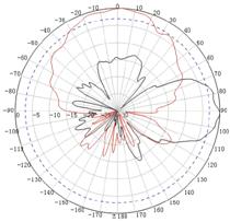
Table 11 5 GHz antenna radiation patterns of the WA530X AP
Central frequency | Antenna radiation patterns | |
Vertical plane | Horizontal plane | |
5150 MHz |
|
|
5550 MHz |
|
|
5850 MHz |
|
|