- Table of Contents
-
- 07-MPLS Configuration Examples
- 01-H3C_HoVPN_Configuration_Examples
- 02-H3C_MCE_Configuration_Examples
- 03-H3C_MPLS_L2VPN_Configuration_Examples
- 04-H3C_MPLS_L3VPN_Configuration_Examples
- 05-H3C_MPLS_TE_Configuration_Examples
- 06-H3C_MPLS_TE_Forwarding_Adjacency_Configuration_Examples
- 07-H3C_Basic_MPLS_Configuration_Examples
- 08-H3C_VPLS_Configuration_Examples
- 09-H3C_GRE Tunnel Access to MPLS L3VPN Configuration Examples
- Related Documents
-
| Title | Size | Download |
|---|---|---|
| 08-H3C_VPLS_Configuration_Examples | 400.97 KB |
H3C VPLS Configuration Examples
Software version: Release 7577P04
Document version: 6W100-20190330
Copyright © 2019 New H3C Technologies Co., Ltd. All rights reserved.
No part of this manual may be reproduced or transmitted in any form or by any means without prior written consent of New H3C Technologies Co., Ltd.
Except for the trademarks of New H3C Technologies Co., Ltd., any trademarks that may be mentioned in this document are the property of their respective owners.
The information in this document is subject to change without notice.
Contents
Example: Configuring full-mesh LDP VPLS
Example: Configuring full-mesh LDP VPLS using BGP auto-discovery
Example: Configuring full-mesh BGP VPLS
Example: Configuring H-VPLS with LSP access
Example: Configuring H-VPLS with QinQ access
Introduction
This document provides Virtual Private LAN Service (VPLS) configuration examples.
VPLS delivers point-to-multipoint L2VPN services over an MPLS or IP backbone. The provider backbone emulates a switch to connect all geographically dispersed sites for each customer network. The backbone is transparent to the customer sites, which can communicate with each other as if they were on the same LAN.
VPLS has two networking models: full mesh and H-VPLS. The full mesh model requires a full mesh of PWs among all PEs and applies to networks that have a small number of PEs. The H-VPLS model classifies PEs to User facing-Provider Edge (UPE) devices and Network Provider Edge (NPE) devices. NPEs are fully meshed and UPEs establish PWs only with the neighbor NPEs. H-VPLS applies to complicated networks that have a large number of PEs.
The following table shows the VPLS networking models and their application scenarios:
|
Networking model |
Application scenario |
|
Full-mesh VPLS using LDP signaling |
A few sites exist and no new sites will be added. |
|
Full-mesh VPLS using BGP auto-discovery and LDP signaling |
A large number of sites exist and no new sites will be added. |
|
Full-mesh VPLS using BGP signaling |
A large number of sites exist and new sites will be added. |
|
H-VPLS with LSP access |
UPEs support MPLS. In this mode, MPLS LSP is used at the access layer. |
|
H-VPLS with QinQ access |
UPEs do not support MPLS. In this mode, Ethernet QinQ tunneling is used at the access layer. |
Prerequisites
The configuration examples in this document were created and verified in a lab environment, and all the devices were started with the factory default configuration. When you are working on a live network, make sure you understand the potential impact of every command on your network.
This document assumes that you have basic knowledge of VPLS.
Example: Configuring full-mesh LDP VPLS
Network configuration
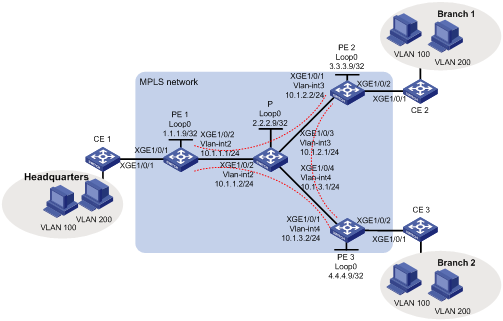
As shown in Figure 1, the MPLS network provides L2VPN services for a company. The company has a headquarters and two branches, and it will not add sites in the future.
Configure full-mesh VPLS using LDP signaling to allow communication among the three sites at Layer 2.
Analysis
To meet the network requirements, you must perform the following tasks:
· To implement LDP VPLS over the MPLS backbone, you must perform the following tasks:
¡ Establish LDP LSPs on the MPLS backbone as public tunnels to deliver the private data over the MPLS network.
¡ Configure an LDP PW between any two PEs to forward data among the branches.
¡ Configure service instances and match criteria on the CE-facing interfaces of PEs to identify packets to be transported by VPLS.
· To implement VLAN isolation among the sites, create VSIs user_a and user_b. Bind VSI user_a to the service instance that matches packets of VLAN 100, and bind VSI user_b to the service instance that matches packets of VLAN 200.
Procedures
1. Configure an IGP on the MPLS backbone to ensure IP connectivity within the backbone:
# On PE 1, configure an IP address for Loopback 0.
<PE1> system-view
[PE1] interface loopback 0
[PE1-LoopBack0] ip address 1.1.1.9 32
[PE1-LoopBack0] quit
# On PE 1, create VLAN 2 and assign Ten-GigabitEthernet 1/0/2 to the VLAN.
[PE1] vlan 2
[PE1-vlan2] port ten-gigabitethernet 1/0/2
[PE1-vlan2] quit
# On PE 1, configure VLAN-interface 2.
[PE1] interface vlan-interface 2
[PE1-Vlan-interface2] ip address 10.1.1.1 24
[PE1-Vlan-interface2] quit
# On PE 1, configure OSPF.
[PE1] ospf
[PE1-ospf-1] area 0
[PE1-ospf-1-area-0.0.0.0] network 10.1.1.0 0.0.0.255
[PE1-ospf-1-area-0.0.0.0] network 1.1.1.9 0.0.0.0
[PE1-ospf-1-area-0.0.0.0] quit
[PE1-ospf-1] quit
# On PE 2, configure an IP address for Loopback 0.
<PE2> system-view
[PE2] interface loopback 0
[PE2-LoopBack0] ip address 3.3.3.9 32
[PE2-LoopBack0] quit
# On PE 2, create VLAN 3 and assign Ten-GigabitEthernet 1/0/1 to the VLAN.
[PE2] vlan 3
[PE2-vlan3] port ten-gigabitethernet 1/0/1
[PE2-vlan3] quit
# On PE 2, configure VLAN-interface 3.
[PE2] interface vlan-interface 3
[PE2-Vlan-interface3] ip address 10.1.2.2 24
[PE2-Vlan-interface3] quit
# On PE 2, configure OSPF.
[PE2] ospf
[PE2-ospf-1] area 0
[PE2-ospf-1-area-0.0.0.0] network 10.1.2.0 0.0.0.255
[PE2-ospf-1-area-0.0.0.0] network 3.3.3.9 0.0.0.0
[PE2-ospf-1-area-0.0.0.0] quit
[PE2-ospf-1] quit
# On PE 3, configure an IP address for Loopback 0.
<PE3> system-view
[PE3] interface loopback 0
[PE3-LoopBack0] ip address 4.4.4.9 32
[PE3-LoopBack0] quit
# On PE 3, create VLAN 4 and assign Ten-GigabitEthernet 1/0/1 to the VLAN.
[PE3] vlan 4
[PE3-vlan4] port ten-gigabitethernet 1/0/1
[PE3-vlan4] quit
# On PE 3, configure VLAN-interface 4.
[PE3] interface vlan-interface 4
[PE3-Vlan-interface4] ip address 10.1.3.2 24
[PE3-Vlan-interface4] quit
# On PE 3, configure OSPF.
[PE3] ospf
[PE3-ospf-1] area 0
[PE3-ospf-1-area-0.0.0.0] network 10.1.3.0 0.0.0.255
[PE3-ospf-1-area-0.0.0.0] network 4.4.4.9 0.0.0.0
[PE3-ospf-1-area-0.0.0.0] quit
[PE3-ospf-1] quit
# On P, configure an IP address for Loopback 0.
<P> system-view
[P] interface loopback 0
[P-LoopBack0] ip address 2.2.2.9 32
[P-LoopBack0] quit
# On P, create VLAN 2 and assign Ten-GigabitEthernet 1/0/2 to the VLAN.
[P] vlan 2
[P-vlan2] port ten-gigabitethernet 1/0/2
[P-vlan2] quit
# On P, configure VLAN-interface 2.
[P] interface vlan-interface 2
[P-Vlan-interface2] ip address 10.1.1.2 24
[P-Vlan-interface2] quit
# On P, create VLAN 3 and assign Ten-GigabitEthernet 1/0/3 to the VLAN.
[P] vlan 3
[P-vlan3] port ten-gigabitethernet 1/0/3
[P-vlan3] quit
# On P, configure VLAN-interface 3.
[P] interface vlan-interface 3
[P-Vlan-interface3] ip address 10.1.2.1 24
[P-Vlan-interface3] quit
# On P, create VLAN 4 and assign Ten-GigabitEthernet 1/0/4 to the VLAN.
[P] vlan 4
[P-vlan4] port ten-gigabitethernet 1/0/4
[P-vlan4] quit
# On P, configure VLAN-interface 4.
[P] interface vlan-interface 4
[P-Vlan-interface4] ip address 10.1.3.1 24
[P-Vlan-interface4] quit
# On P, configure OSPF.
[P] ospf
[P-ospf-1] area 0
[P-ospf-1-area-0.0.0.0] network 10.1.1.0 0.0.0.255
[P-ospf-1-area-0.0.0.0] network 10.1.2.0 0.0.0.255
[P-ospf-1-area-0.0.0.0] network 10.1.3.0 0.0.0.255
[P-ospf-1-area-0.0.0.0] network 2.2.2.9 0.0.0.0
[P-ospf-1-area-0.0.0.0] quit
[P-ospf-1] quit
2. Configure basic MPLS and MPLS LDP on the MPLS backbone to establish LDP LSPs:
# On PE 1, configure an LSR ID.
[PE1] mpls lsr-id 1.1.1.9
# On PE 1, enable LDP globally.
[PE1] mpls ldp
[PE1-ldp] quit
# On PE 1, enable MPLS and LDP on VLAN-interface 2.
[PE1] interface vlan-interface 2
[PE1-Vlan-interface2] mpls enable
[PE1-Vlan-interface2] mpls ldp enable
[PE1-Vlan-interface2] quit
# On PE 2, configure an LSR ID.
[PE2] mpls lsr-id 3.3.3.9
# On PE 2, enable LDP globally.
[PE2] mpls ldp
[PE2-ldp] quit
# On PE 2, enable MPLS and LDP on VLAN-interface 3.
[PE2] interface vlan-interface 3
[PE2-Vlan-interface3] mpls enable
[PE2-Vlan-interface3] mpls ldp enable
[PE2-Vlan-interface3] quit
# On PE 3, configure an LSR ID.
[PE3] mpls lsr-id 4.4.4.9
# On PE 3, enable LDP globally.
[PE3] mpls ldp
[PE3-ldp] quit
# On PE 3, enable MPLS and LDP on VLAN-interface 4.
[PE3] interface vlan-interface 4
[PE3-Vlan-interface4] mpls enable
[PE3-Vlan-interface4] mpls ldp enable
[PE3-Vlan-interface4] quit
# On P, configure an LSR ID.
[P] mpls lsr-id 2.2.2.9
# On P, enable LDP globally.
[P] mpls ldp
[P-ldp] quit
# On P, enable MPLS and LDP on VLAN-interface 2.
[P] interface vlan-interface 2
[P-Vlan-interface2] mpls enable
[P-Vlan-interface2] mpls ldp enable
[P-Vlan-interface2] quit
# On P, enable MPLS and LDP on VLAN-interface 3.
[P] interface vlan-interface 3
[P-Vlan-interface3] mpls enable
[P-Vlan-interface3] mpls ldp enable
[P-Vlan-interface3] quit
# On P, enable MPLS and LDP on VLAN-interface 4.
[P] interface vlan-interface 4
[P-Vlan-interface4] mpls enable
[P-Vlan-interface4] mpls ldp enable
[P-Vlan-interface4] quit
3. Configure VSIs and LDP PWs:
# On PE 1, enable MPLS L2VPN globally.
[PE1] l2vpn enable
# On PE 1, create VSI user_a and configure the VSI to use LDP as the PW signaling protocol.
[PE1] vsi user_a
[PE1-vsi-user_a] pwsignaling ldp
# On PE 1, specify PE 2 and PE 3 as the peer PEs, and set the PW ID to 500.
[PE1-vsi-user_a-ldp] peer 3.3.3.9 pw-id 500
[PE1-vsi-user_a-ldp-3.3.3.9-500] quit
[PE1-vsi-user_a-ldp] peer 4.4.4.9 pw-id 500
[PE1-vsi-user_a-ldp-4.4.4.9-500] quit
[PE1-vsi-user_a-ldp] quit
[PE1-vsi-user_a] quit
# On PE 1, create VSI user_b and configure the VSI to use LDP as the PW signaling protocol.
[PE1] vsi user_b
[PE1-vsi-user_b] pwsignaling ldp
# On PE 1, specify PE 2 and PE 3 as the peer PEs, and set the PW ID to 600.
[PE1-vsi-user_b-ldp] peer 3.3.3.9 pw-id 600
[PE1-vsi-user_b-ldp-3.3.3.9-600] quit
[PE1-vsi-user_b-ldp] peer 4.4.4.9 pw-id 600
[PE1-vsi-user_b-ldp-4.4.4.9-600] quit
[PE1-vsi-user_b-ldp] quit
[PE1-vsi-user_b] quit
# On PE 2, enable MPLS L2VPN globally.
[PE2] l2vpn enable
# On PE 2, create VSI user_a and configure the VSI to use LDP as the PW signaling protocol.
[PE2] vsi user_a
[PE2-vsi-user_a] pwsignaling ldp
# On PE 2, specify PE 1 and PE 3 as the peer PEs, and set the PW ID to 500.
[PE2-vsi-user_a-ldp] peer 1.1.1.9 pw-id 500
[PE2-vsi-user_a-ldp-1.1.1.9-500] quit
[PE2-vsi-user_a-ldp] peer 4.4.4.9 pw-id 500
[PE2-vsi-user_a-ldp-4.4.4.9-500] quit
[PE2-vsi-user_a-ldp] quit
[PE2-vsi-user_a] quit
# On PE 2, create VSI user_b and configure the VSI to use LDP as the PW signaling protocol.
[PE2] vsi user_b
[PE2-vsi-user_b] pwsignaling ldp
# On PE 2, specify PE 1 and PE 3 as the peer PEs, and set the PW ID to 600.
[PE2-vsi-user_b-ldp] peer 1.1.1.9 pw-id 600
[PE2-vsi-user_b-ldp-1.1.1.9-600] quit
[PE2-vsi-user_b-ldp] peer 4.4.4.9 pw-id 600
[PE2-vsi-user_b-ldp-4.4.4.9-600] quit
[PE2-vsi-user_b-ldp] quit
[PE2-vsi-user_b] quit
# On PE 3, enable MPLS L2VPN globally.
[PE3] l2vpn enable
# On PE 3, create VSI user_a and configure the VSI to use LDP as the PW signaling protocol.
[PE3] vsi user_a
[PE3-vsi-user_a] pwsignaling ldp
# On PE 3, specify PE 1 and PE 2 as the peer PEs, and set the PW ID to 500.
[PE3-vsi-user_a-ldp] peer 1.1.1.9 pw-id 500
[PE3-vsi-user_a-ldp-1.1.1.9-500] quit
[PE3-vsi-user_a-ldp] peer 3.3.3.9 pw-id 500
[PE3-vsi-user_a-ldp-3.3.3.9-500] quit
[PE3-vsi-user_a-ldp] quit
[PE3-vsi-user_a] quit
# On PE 3, create VSI user_b and configure the VSI to use LDP as the PW signaling protocol.
[PE3] vsi user_b
[PE3-vsi-user_b] pwsignaling ldp
# On PE 3, specify PE 1 and PE 2 as the peer PEs, and set the PW ID to 600.
[PE3-vsi-user_b-ldp] peer 1.1.1.9 pw-id 600
[PE3-vsi-user_b-ldp-1.1.1.9-600] quit
[PE3-vsi-user_b-ldp] peer 3.3.3.9 pw-id 600
[PE3-vsi-user_b-ldp-3.3.3.9-600] quit
[PE3-vsi-user_b-ldp] quit
[PE3-vsi-user_b] quit
4. Configure service instances for different VLANs and bind the service instances to VSIs:
# On PE 1, create service instance 100 on Ten-GigabitEthernet 1/0/1 to match packets of VLAN 100, and bind the service instance to VSI user_a.
[PE1] interface ten-gigabitethernet 1/0/1
[PE1-Ten-GigabitEthernet1/0/1] service-instance 100
[PE1-Ten-GigabitEthernet1/0/1-srv100] encapsulation s-vid 100
[PE1-Ten-GigabitEthernet1/0/1-srv100] xconnect vsi user_a
[PE1-Ten-GigabitEthernet1/0/1-srv100] quit
# On PE 1, create service instance 200 on Ten-GigabitEthernet 1/0/1 to match packets of VLAN 200, and bind the service instance to VSI user_b.
[PE1-Ten-GigabitEthernet1/0/1] service-instance 200
[PE1-Ten-GigabitEthernet1/0/1-srv200] encapsulation s-vid 200
[PE1-Ten-GigabitEthernet1/0/1-srv200] xconnect vsi user_b
[PE1-Ten-GigabitEthernet1/0/1-srv200] quit
[PE1-Ten-GigabitEthernet1/0/1] quit
# On PE 2, create service instance 100 on Ten-GigabitEthernet 1/0/2 to match packets of VLAN 100, and bind the service instance to VSI user_a.
[PE2] interface ten-gigabitethernet 1/0/2
[PE2-Ten-GigabitEthernet1/0/2] service-instance 100
[PE2-Ten-GigabitEthernet1/0/2-srv100] encapsulation s-vid 100
[PE2-Ten-GigabitEthernet1/0/2-srv100] xconnect vsi user_a
[PE2-Ten-GigabitEthernet1/0/2-srv100] quit
# On PE 2, create service instance 200 on Ten-GigabitEthernet 1/0/2 to match packets of VLAN 200, and bind the service instance to VSI user_b.
[PE2-Ten-GigabitEthernet1/0/2] service-instance 200
[PE2-Ten-GigabitEthernet1/0/2-srv200] encapsulation s-vid 200
[PE2-Ten-GigabitEthernet1/0/2-srv200] xconnect vsi user_b
[PE2-Ten-GigabitEthernet1/0/2-srv200] quit
[PE2-Ten-GigabitEthernet1/0/2] quit
# On PE 3, create service instance 100 on Ten-GigabitEthernet 1/0/2 to match packets of VLAN 100, and bind the service instance to VSI user_a.
[PE3] interface ten-gigabitethernet 1/0/2
[PE3-Ten-GigabitEthernet1/0/2] service-instance 100
[PE3-Ten-GigabitEthernet1/0/2-srv100] encapsulation s-vid 100
[PE3-Ten-GigabitEthernet1/0/2-srv100] xconnect vsi user_a
[PE3-Ten-GigabitEthernet1/0/2-srv100] quit
# On PE 3, create service instance 200 on Ten-GigabitEthernet 1/0/2 to match packets of VLAN 200, and bind the service instance to VSI user_b.
[PE3-Ten-GigabitEthernet1/0/2] service-instance 200
[PE3-Ten-GigabitEthernet1/0/2-srv200] encapsulation s-vid 200
[PE3-Ten-GigabitEthernet1/0/2-srv200] xconnect vsi user_b
[PE3-Ten-GigabitEthernet1/0/2-srv200] quit
[PE3-Ten-GigabitEthernet1/0/2] quit
5. Allow CE access to PEs:
# On CE 1, configure the interface connected to the PE to permit tagged packets from the customer VLANs.
<CE1> system-view
[CE1] vlan 100
[CE1-vlan100] quit
[CE1] vlan 200
[CE1-vlan200] quit
[CE1] interface ten-gigabitethernet 1/0/1
[CE1-Ten-GigabitEthernet1/0/1] port link-type trunk
[CE1-Ten-GigabitEthernet1/0/1] port trunk permit vlan 100 200
# Configure other CEs in the same way that CE 1 is configured. (Details not shown.)
Verifying the configuration
# Verify that LDP LSPs have been established on each switch in the MPLS network. This example uses PE 1.
[PE1] display mpls ldp lsp
Status Flags: * - stale, L - liberal
Statistics:
FECs: 4 Ingress LSPs: 3 Transit LSPs: 3 Egress LSPs: 1
FEC In/Out Label Nexthop OutInterface
1.1.1.9/32 3/-
-/1151(L)
-/1151(L)
-/1151(L)
2.2.2.9/32 -/3 10.1.1.2 Vlan2
1151/3 10.1.1.2 Vlan2
-/1150(L)
-/1150(L)
3.3.3.9/32 -/1150 10.1.1.2 Vlan2
1150/1150 10.1.1.2 Vlan2
-/3(L)
-/1149(L)
4.4.4.9/32 -/1149 10.1.1.2 Vlan2
1149/1149 10.1.1.2 Vlan2
-/1149(L)
-/3(L)
# Verify that LDP PWs in up state have been established on each PE. This example uses PE 1.
[PE1] display l2vpn pw
Flags: M - main, B - backup, H - hub link, S - spoke link, N - no split horizon
Total number of PWs: 4
4 up, 0 blocked, 0 down, 0 defect, 0 idle, 0 duplicate
VSI Name: user_a
Peer PW ID/Rmt Site In/Out Label Proto Flag Link ID State
3.3.3.9 500 131198/131198 LDP M 64 Up
4.4.4.9 500 131199/1150 LDP M 65 Up
VSI Name: user_b
Peer PW ID/Rmt Site In/Out Label Proto Flag Link ID State
3.3.3.9 600 131196/131196 LDP M 64 Up
4.4.4.9 600 131197/1147 LDP M 65 Up
# Verify that hosts in the same VLAN but different sites can ping each other. (Details not shown.)
Configuration files
· PE 1:
#
ospf 1
area 0.0.0.0
network 1.1.1.9 0.0.0.0
network 10.1.1.0 0.0.0.255
#
mpls lsr-id 1.1.1.9
#
vlan 2
#
mpls ldp
#
l2vpn enable
#
vsi user_a
pwsignaling ldp
peer 3.3.3.9 pw-id 500
peer 4.4.4.9 pw-id 500
#
vsi user_b
pwsignaling ldp
peer 3.3.3.9 pw-id 600
peer 4.4.4.9 pw-id 600
#
interface LoopBack0
ip address 1.1.1.9 255.255.255.255
#
interface Vlan-interface2
ip address 10.1.1.1 255.255.255.0
mpls enable
mpls ldp enable
#
interface Ten-GigabitEthernet1/0/1
port link-mode bridge
service-instance 100
encapsulation s-vid 100
xconnect vsi user_a
service-instance 200
encapsulation s-vid 200
xconnect vsi user_b
#
interface Ten-GigabitEthernet1/0/2
port link-mode bridge
port access vlan 2
#
· PE 2:
ospf 1
area 0.0.0.0
network 10.1.2.0 0.0.0.255
network 3.3.3.9 0.0.0.0
#
mpls lsr-id 3.3.3.9
#
vlan 3
#
mpls ldp
#
l2vpn enable
#
vsi user_a
pwsignaling ldp
peer 1.1.1.9 pw-id 500
peer 4.4.4.9 pw-id 500
#
vsi user_b
pwsignaling ldp
peer 1.1.1.9 pw-id 600
peer 4.4.4.9 pw-id 600
#
interface LoopBack0
ip address 3.3.3.9 255.255.255.255
#
interface Vlan-interface3
ip address 10.1.2.2 255.255.255.0
mpls enable
mpls ldp enable
#
interface Ten-GigabitEthernet1/0/1
port link-mode bridge
port access vlan 3
#
interface Ten-GigabitEthernet1/0/2
port link-mode bridge
service-instance 100
encapsulation s-vid 100
xconnect vsi user_a
service-instance 200
encapsulation s-vid 200
xconnect vsi user_b
#
· PE 3:
#
ospf 1
area 0.0.0.0
network 10.1.3.0 0.0.0.255
network 4.4.4.9 0.0.0.0
#
mpls lsr-id 4.4.4.9
#
vlan 4
#
mpls ldp
#
l2vpn enable
#
vsi user_a
pwsignaling ldp
peer 1.1.1.9 pw-id 500
peer 3.3.3.9 pw-id 500
#
vsi user_b
pwsignaling ldp
peer 1.1.1.9 pw-id 600
peer 3.3.3.9 pw-id 600
#
interface LoopBack0
ip address 4.4.4.9 255.255.255.255
#
interface Vlan-interface4
ip address 10.1.3.2 255.255.255.0
mpls enable
mpls ldp enable
#
interface Ten-GigabitEthernet1/0/1
port link-mode bridge
port access vlan 4
#
interface Ten-GigabitEthernet1/0/2
port link-mode bridge
service-instance 100
encapsulation s-vid 100
xconnect vsi user_a
service-instance 200
encapsulation s-vid 200
xconnect vsi user_b
#
· P:
#
ospf 1
area 0.0.0.0
network 10.1.1.0 0.0.0.255
network 10.1.2.0 0.0.0.255
network 10.1.3.0 0.0.0.255
network 2.2.2.9 0.0.0.0
#
mpls lsr-id 2.2.2.9
#
vlan 2 to 4
#
mpls ldp
#
interface LoopBack0
ip address 2.2.2.9 255.255.255.255
#
interface Vlan-interface2
ip address 10.1.1.2 255.255.255.0
mpls enable
mpls ldp enable
#
interface Vlan-interface3
ip address 10.1.2.1 255.255.255.0
mpls enable
mpls ldp enable
#
interface Vlan-interface4
ip address 10.1.3.1 255.255.255.0
mpls enable
mpls ldp enable
#
interface Ten-GigabitEthernet1/0/2
port link-mode bridge
port access vlan 2
#
interface Ten-GigabitEthernet1/0/3
port link-mode bridge
port access vlan 3
#
interface Ten-GigabitEthernet1/0/4
port link-mode bridge
port access vlan 4
#
· CE 1 through CE 3:
#
vlan 100
#
vlan 200
#
interface Ten-GigabitEthernet1/0/1
port link-mode bridge
port link-type trunk
port trunk permit vlan 100 200
#
Example: Configuring full-mesh LDP VPLS using BGP auto-discovery
Network configuration
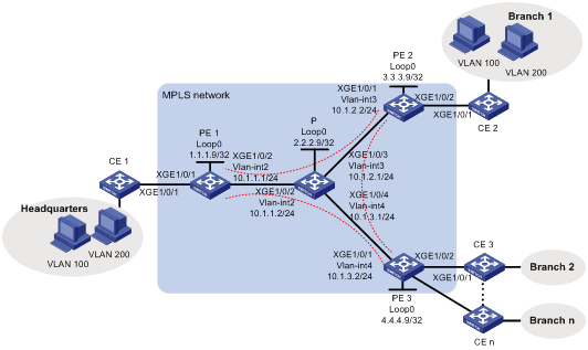
As shown in Figure 2, the MPLS network provides L2VPN services for a company. The company has a headquarters and a large number of branches, and it will not add sites in the future.
Configure full-mesh VPLS using BGP auto-discovery and LDP signaling to allow communication among all the sites at Layer 2.
Analysis
To meet the network requirements, you must perform the following tasks:
· To implement LDP VPLS using BGP auto-discovery over the MPLS backbone, you must perform the following tasks:
¡ Establish LDP LSPs on the MPLS backbone as public tunnels to deliver the private data over the MPLS network.
¡ Configure a BGP auto-discovery LDP PW between any two PEs to forward data among the branches.
¡ Configure service instances and match criteria on the CE-facing interfaces of PEs to identify packets to be transported by VPLS.
· To implement VLAN isolation among the sites, create VSIs user_a and user_b. Bind VSI user_a to the service instance that matches packets of VLAN 100, and bind VSI user_b to the service instance that matches packets of VLAN 200.
Procedures
1. Configure an IGP on the MPLS backbone to ensure IP connectivity within the backbone:
# On PE 1, configure an IP address for Loopback 0.
<PE1> system-view
[PE1] interface loopback 0
[PE1-LoopBack0] ip address 1.1.1.9 32
[PE1-LoopBack0] quit
# On PE 1, create VLAN 2 and assign Ten-GigabitEthernet 1/0/2 to the VLAN.
[PE1] vlan 2
[PE1-vlan2] port ten-gigabitethernet 1/0/2
[PE1-vlan2] quit
# On PE 1, configure VLAN-interface 2.
[PE1] interface vlan-interface 2
[PE1-Vlan-interface2] ip address 10.1.1.1 24
[PE1-Vlan-interface2] quit
# On PE 1, configure OSPF.
[PE1] ospf
[PE1-ospf-1] area 0
[PE1-ospf-1-area-0.0.0.0] network 10.1.1.0 0.0.0.255
[PE1-ospf-1-area-0.0.0.0] network 1.1.1.9 0.0.0.0
[PE1-ospf-1-area-0.0.0.0] quit
[PE1-ospf-1] quit
# On PE 2, configure an IP address for Loopback 0.
<PE2> system-view
[PE2] interface loopback 0
[PE2-LoopBack0] ip address 3.3.3.9 32
[PE2-LoopBack0] quit
# On PE 2, create VLAN 3 and assign Ten-GigabitEthernet 1/0/1 to the VLAN.
[PE2] vlan 3
[PE2-vlan3] port ten-gigabitethernet 1/0/1
[PE2-vlan3] quit
# On PE 2, configure VLAN-interface 3.
[PE2] interface vlan-interface 3
[PE2-Vlan-interface3] ip address 10.1.2.2 24
[PE2-Vlan-interface3] quit
# On PE 2, configure OSPF.
[PE2] ospf
[PE2-ospf-1] area 0
[PE2-ospf-1-area-0.0.0.0] network 10.1.2.0 0.0.0.255
[PE2-ospf-1-area-0.0.0.0] network 3.3.3.9 0.0.0.0
[PE2-ospf-1-area-0.0.0.0] quit
[PE2-ospf-1] quit
# On PE 3, configure an IP address for Loopback 0.
<PE3> system-view
[PE3] interface loopback 0
[PE3-LoopBack0] ip address 4.4.4.9 32
[PE3-LoopBack0] quit
# On PE 3, create VLAN 4 and assign Ten-GigabitEthernet 1/0/1 to the VLAN.
[PE3] vlan 4
[PE3-vlan4] port ten-gigabitethernet 1/0/1
[PE3-vlan4] quit
# On PE 3, configure VLAN-interface 4.
[PE3] interface vlan-interface 4
[PE3-Vlan-interface4] ip address 10.1.3.2 24
[PE3-Vlan-interface4] quit
# On PE 3, configure OSPF.
[PE3] ospf
[PE3-ospf-1] area 0
[PE3-ospf-1-area-0.0.0.0] network 10.1.3.0 0.0.0.255
[PE3-ospf-1-area-0.0.0.0] network 4.4.4.9 0.0.0.0
[PE3-ospf-1-area-0.0.0.0] quit
[PE3-ospf-1] quit
# On P, configure an IP address for Loopback 0.
<P> system-view
[P] interface loopback 0
[P-LoopBack0] ip address 2.2.2.9 32
[P-LoopBack0] quit
# On P, create VLAN 2 and assign Ten-GigabitEthernet 1/0/2 to the VLAN.
[P] vlan 2
[P-vlan2] port ten-gigabitethernet 1/0/2
[P-vlan2] quit
# On P, configure VLAN-interface 2.
[P] interface vlan-interface 2
[P-Vlan-interface2] ip address 10.1.1.2 24
[P-Vlan-interface2] quit
# On P, create VLAN 3 and assign Ten-GigabitEthernet 1/0/3 to the VLAN.
[P] vlan 3
[P-vlan3] port ten-gigabitethernet 1/0/3
[P-vlan3] quit
# On P, configure VLAN-interface 3.
[P] interface vlan-interface 3
[P-Vlan-interface3] ip address 10.1.2.1 24
[P-Vlan-interface3] quit
# On P, create VLAN 4 and assign Ten-GigabitEthernet 1/0/4 to the VLAN.
[P] vlan 4
[P-vlan4] port ten-gigabitethernet 1/0/4
[P-vlan4] quit
# On P, configure VLAN-interface 4.
[P] interface vlan-interface 4
[P-Vlan-interface4] ip address 10.1.3.1 24
[P-Vlan-interface4] quit
# On P, configure OSPF.
[P] ospf
[P-ospf-1] area 0
[P-ospf-1-area-0.0.0.0] network 10.1.1.0 0.0.0.255
[P-ospf-1-area-0.0.0.0] network 10.1.2.0 0.0.0.255
[P-ospf-1-area-0.0.0.0] network 10.1.3.0 0.0.0.255
[P-ospf-1-area-0.0.0.0] network 2.2.2.9 0.0.0.0
[P-ospf-1-area-0.0.0.0] quit
[P-ospf-1] quit
2. Configure basic MPLS and MPLS LDP on the MPLS backbone to establish LDP LSPs:
# On PE 1, configure an LSR ID.
[PE1] mpls lsr-id 1.1.1.9
# On PE 1, enable LDP globally.
[PE1] mpls ldp
[PE1-ldp] quit
# On PE 1, enable MPLS and LDP on VLAN-interface 2.
[PE1] interface vlan-interface 2
[PE1-Vlan-interface2] mpls enable
[PE1-Vlan-interface2] mpls ldp enable
[PE1-Vlan-interface2] quit
# On PE 2, configure an LSR ID.
[PE2] mpls lsr-id 3.3.3.9
# On PE 2, enable LDP globally.
[PE2] mpls ldp
[PE2-ldp] quit
# On PE 2, enable MPLS and LDP on VLAN-interface 3.
[PE2] interface vlan-interface 3
[PE2-Vlan-interface3] mpls enable
[PE2-Vlan-interface3] mpls ldp enable
[PE2-Vlan-interface3] quit
# On PE 3, configure an LSR ID.
[PE3] mpls lsr-id 4.4.4.9
# On PE 3, enable LDP globally.
[PE3] mpls ldp
[PE3-ldp] quit
# On PE 3, enable MPLS and LDP on VLAN-interface 4.
[PE3] interface vlan-interface 4
[PE3-Vlan-interface4] mpls enable
[PE3-Vlan-interface4] mpls ldp enable
[PE3-Vlan-interface4] quit
# On P, configure an LSR ID.
[P] mpls lsr-id 2.2.2.9
# On P, enable LDP globally.
[P] mpls ldp
[P-ldp] quit
# On P, enable MPLS and LDP on VLAN-interface 2.
[P] interface vlan-interface 2
[P-Vlan-interface2] mpls enable
[P-Vlan-interface2] mpls ldp enable
[P-Vlan-interface2] quit
# On P, enable MPLS and LDP on VLAN-interface 3.
[P] interface vlan-interface 3
[P-Vlan-interface3] mpls enable
[P-Vlan-interface3] mpls ldp enable
[P-Vlan-interface3] quit
# On P, enable MPLS and LDP on VLAN-interface 4.
[P] interface vlan-interface 4
[P-Vlan-interface4] mpls enable
[P-Vlan-interface4] mpls ldp enable
[P-Vlan-interface4] quit
3. Configure VSIs and BGP auto-discovery LDP PWs:
# On PE 1, establish IBGP connections to PE 2 and PE 3.
[PE1] bgp 100
[PE1-bgp] peer 3.3.3.9 as-number 100
[PE1-bgp] peer 3.3.3.9 connect-interface loopback 0
[PE1-bgp] peer 4.4.4.9 as-number 100
[PE1-bgp] peer 4.4.4.9 connect-interface loopback 0
# On PE 1, enable BGP to exchange L2VPN information with the peers.
[PE1-bgp] address-family l2vpn
[PE1-bgp-l2vpn] peer 3.3.3.9 enable
[PE1-bgp-l2vpn] peer 4.4.4.9 enable
[PE1-bgp-l2vpn] quit
[PE1-bgp] quit
# On PE 1, enable MPLS L2VPN globally.
[PE1] l2vpn enable
# On PE 1, create VSI user_a and enable the VSI to automatically discover neighbors through BGP.
[PE1] vsi user_a
[PE1-vsi-user_a] auto-discovery bgp
# On PE 1, configure an RD and route targets for the VSI.
[PE1-vsi-user_a-auto] route-distinguisher 100:1
[PE1-vsi-user_a-auto] vpn-target 111:1
# On PE 1, use LDP to establish a PW to a remote PE discovered by BGP.
[PE1-vsi-user_a-auto] signaling-protocol ldp
# On PE 1, configure the VPLS ID as 100:100 for the VSI.
[PE1-vsi-user_a-auto-ldp] vpls-id 100:100
[PE1-vsi-user_a-auto-ldp] quit
[PE1-vsi-user_a-auto] quit
[PE1-vsi-user_a] quit
# On PE 1, create VSI user_b and enable the VSI to automatically discover neighbors through BGP.
[PE1] vsi user_b
[PE1-vsi-user_b] auto-discovery bgp
# On PE 1, configure an RD and route targets for the VSI.
[PE1-vsi-user_b-auto] route-distinguisher 200:1
[PE1-vsi-user_b-auto] vpn-target 222:1
# On PE 1, use LDP to establish a PW to a remote PE discovered by BGP.
[PE1-vsi-user_b-auto] signaling-protocol ldp
# On PE 1, configure the VPLS ID as 200:200 for the VSI.
[PE1-vsi-user_b-auto-ldp] vpls-id 200:200
[PE1-vsi-user_b-auto-ldp] quit
[PE1-vsi-user_b-auto] quit
[PE1-vsi-user_b] quit
# On PE 2, establish IBGP connections to PE 1 and PE 3.
[PE2] bgp 100
[PE2-bgp] peer 1.1.1.9 as-number 100
[PE2-bgp] peer 1.1.1.9 connect-interface loopback 0
[PE2-bgp] peer 4.4.4.9 as-number 100
[PE2-bgp] peer 4.4.4.9 connect-interface loopback 0
# On PE 2, enable BGP to exchange L2VPN information with the peers.
[PE2-bgp] address-family l2vpn
[PE2-bgp-l2vpn] peer 1.1.1.9 enable
[PE2-bgp-l2vpn] peer 4.4.4.9 enable
[PE2-bgp-l2vpn] quit
[PE2-bgp] quit
# On PE 2, enable MPLS L2VPN globally.
[PE2] l2vpn enable
# On PE 2, create VSI user_a and enable the VSI to automatically discover neighbors through BGP.
[PE2] vsi user_a
[PE2-vsi-user_a] auto-discovery bgp
# On PE 2, configure an RD and route targets for the VSI.
[PE2-vsi-user_a-auto] route-distinguisher 100:1
[PE2-vsi-user_a-auto] vpn-target 111:1
# On PE 2, use LDP to establish a PW to a remote PE discovered by BGP.
[PE2-vsi-user_a-auto] signaling-protocol ldp
# On PE 2, configure the VPLS ID as 100:100 for the VSI.
[PE2-vsi-user_a-auto-ldp] vpls-id 100:100
[PE2-vsi-user_a-auto-ldp] quit
[PE2-vsi-user_a-auto] quit
[PE2-vsi-user_a] quit
# On PE 2, create VSI user_b and enable the VSI to automatically discover neighbors through BGP.
[PE2] vsi user_b
[PE2-vsi-user_b] auto-discovery bgp
# On PE 2, configure an RD and route targets for the VSI.
[PE2-vsi-user_b-auto] route-distinguisher 200:1
[PE2-vsi-user_b-auto] vpn-target 222:1
# On PE 2, use LDP to establish a PW to a remote PE discovered by BGP.
[PE2-vsi-user_b-auto] signaling-protocol ldp
# On PE 2, configure the VPLS ID as 200:200 for the VSI.
[PE2-vsi-user_b-auto-ldp] vpls-id 200:200
[PE2-vsi-user_b-auto-ldp] quit
[PE2-vsi-user_b-auto] quit
[PE2-vsi-user_b] quit
# On PE 3, establish IBGP connections to PE 1 and PE 2.
[PE3] bgp 100
[PE3-bgp] peer 1.1.1.9 as-number 100
[PE3-bgp] peer 1.1.1.9 connect-interface loopback 0
[PE3-bgp] peer 3.3.3.9 as-number 100
[PE3-bgp] peer 3.3.3.9 connect-interface loopback 0
# On PE 3, enable BGP to exchange L2VPN information with the peers.
[PE3-bgp] address-family l2vpn
[PE3-bgp-l2vpn] peer 1.1.1.9 enable
[PE3-bgp-l2vpn] peer 3.3.3.9 enable
[PE3-bgp-l2vpn] quit
[PE3-bgp] quit
# On PE 3, enable MPLS L2VPN globally.
[PE3] l2vpn enable
# On PE 3, create VSI user_a and enable the VSI to automatically discover neighbors through BGP.
[PE3] vsi user_a
[PE3-vsi-user_a] auto-discovery bgp
# On PE 3, configure an RD and route targets for the VSI.
[PE3-vsi-user_a-auto] route-distinguisher 100:1
[PE3-vsi-user_a-auto] vpn-target 111:1
# On PE 3, use LDP to establish a PW to a remote PE discovered by BGP.
[PE3-vsi-user_a-auto] signaling-protocol ldp
# On PE 3, configure the VPLS ID as 100:100 for the VSI.
[PE3-vsi-user_a-auto-ldp] vpls-id 100:100
[PE3-vsi-user_a-auto-ldp] quit
[PE3-vsi-user_a-auto] quit
[PE3-vsi-user_a] quit
# On PE 3, create VSI user_b and enable the VSI to automatically discover neighbors through BGP.
[PE3] vsi user_b
[PE3-vsi-user_b] auto-discovery bgp
# On PE 3, configure an RD and route targets for the VSI.
[PE3-vsi-user_b-auto] route-distinguisher 200:1
[PE3-vsi-user_b-auto] vpn-target 222:1
# On PE 3, use LDP to establish a PW to a remote PE discovered by BGP.
[PE3-vsi-user_b-auto] signaling-protocol ldp
# On PE 3, configure the VPLS ID as 200:200 for the VSI.
[PE3-vsi-user_b-auto-ldp] vpls-id 200:200
[PE3-vsi-user_b-auto-ldp] quit
[PE3-vsi-user_b-auto] quit
[PE3-vsi-user_b] quit
4. Configure service instances for different VLANs and bind the service instances to VSIs:
# On PE 1, create service instance 100 on Ten-GigabitEthernet 1/0/1 to match packets of VLAN 100, and bind the service instance to VSI user_a.
[PE1] interface ten-gigabitethernet 1/0/1
[PE1-Ten-GigabitEthernet1/0/1] service-instance 100
[PE1-Ten-GigabitEthernet1/0/1-srv100] encapsulation s-vid 100
[PE1-Ten-GigabitEthernet1/0/1-srv100] xconnect vsi user_a
[PE1-Ten-GigabitEthernet1/0/1-srv100] quit
# On PE 1, create service instance 200 on Ten-GigabitEthernet 1/0/1 to match packets of VLAN 200, and bind the service instance to VSI user_b.
[PE1-Ten-GigabitEthernet1/0/1] service-instance 200
[PE1-Ten-GigabitEthernet1/0/1-srv200] encapsulation s-vid 200
[PE1-Ten-GigabitEthernet1/0/1-srv200] xconnect vsi user_b
[PE1-Ten-GigabitEthernet1/0/1-srv200] quit
[PE1-Ten-GigabitEthernet1/0/1] quit
# On PE 2, create service instance 100 on Ten-GigabitEthernet 1/0/2 to match packets of VLAN 100, and bind the service instance to VSI user_a.
[PE2] interface ten-gigabitethernet 1/0/2
[PE2-Ten-GigabitEthernet1/0/2] service-instance 100
[PE2-Ten-GigabitEthernet1/0/2-srv100] encapsulation s-vid 100
[PE2-Ten-GigabitEthernet1/0/2-srv100] xconnect vsi user_a
[PE2-Ten-GigabitEthernet1/0/2-srv100] quit
# On PE 2, create service instance 200 on Ten-GigabitEthernet 1/0/2 to match packets of VLAN 200, and bind the service instance to VSI user_b.
[PE2-Ten-GigabitEthernet1/0/2] service-instance 200
[PE2-Ten-GigabitEthernet1/0/2-srv200] encapsulation s-vid 200
[PE2-Ten-GigabitEthernet1/0/2-srv200] xconnect vsi user_b
[PE2-Ten-GigabitEthernet1/0/2-srv200] quit
[PE2-Ten-GigabitEthernet1/0/2] quit
# On PE 3, create service instance 100 on Ten-GigabitEthernet 1/0/2 to match packets of VLAN 100, and bind the service instance to VSI user_a.
[PE3] interface ten-gigabitethernet 1/0/2
[PE3-Ten-GigabitEthernet1/0/2] service-instance 100
[PE3-Ten-GigabitEthernet1/0/2-srv100] encapsulation s-vid 100
[PE3-Ten-GigabitEthernet1/0/2-srv100] xconnect vsi user_a
[PE3-Ten-GigabitEthernet1/0/2-srv100] quit
# On PE 3, create service instance 200 on Ten-GigabitEthernet 1/0/2 to match packets of VLAN 200, and bind the service instance to VSI user_b.
[PE3-Ten-GigabitEthernet1/0/2] service-instance 200
[PE3-Ten-GigabitEthernet1/0/2-srv200] encapsulation s-vid 200
[PE3-Ten-GigabitEthernet1/0/2-srv200] xconnect vsi user_b
[PE3-Ten-GigabitEthernet1/0/2-srv200] quit
[PE3-Ten-GigabitEthernet1/0/2] quit
# On PE 3, configure other CE-facing interfaces in the same way that Ten-GigabitEthernet 1/0/2 is configured. (Details not shown.)
5. Allow CE access to PEs:
# On CE 1, configure the interface connected to the PE to permit tagged packets from the customer VLANs.
<CE1> system-view
[CE1] vlan 100
[CE1-vlan100] quit
[CE1] vlan 200
[CE1-vlan200] quit
[CE1] interface ten-gigabitethernet 1/0/1
[CE1-Ten-GigabitEthernet1/0/1] port link-type trunk
[CE1-Ten-GigabitEthernet1/0/1] port trunk permit vlan 100 200
# Configure other CEs in the same way that CE 1 is configured. (Details not shown.)
Verifying the configuration
# Verify that LDP LSPs have been established on each switch in the MPLS network. This example uses PE 1.
[PE1] display mpls ldp lsp
Status Flags: * - stale, L - liberal
Statistics:
FECs: 4 Ingress LSPs: 3 Transit LSPs: 3 Egress LSPs: 1
FEC In/Out Label Nexthop OutInterface
1.1.1.9/32 3/-
-/1148(L)
-/1151(L)
-/1151(L)
2.2.2.9/32 -/3 10.1.1.2 Vlan2
1151/3 10.1.1.2 Vlan2
-/1150(L)
-/1150(L)
3.3.3.9/32 -/1146 10.1.1.2 Vlan2
1149/1146 10.1.1.2 Vlan2
-/1149(L)
-/3(L)
4.4.4.9/32 -/1147 10.1.1.2 Vlan2
1150/1147 10.1.1.2 Vlan2
-/3(L)
-/1149(L)
# Verify that LDP PWs in up state have been established on each PE. This example uses PE 1.
[PE1] display l2vpn pw
Flags: M - main, B - backup, H - hub link, S - spoke link, N - no split horizon
Total number of PWs: 4
4 up, 0 blocked, 0 down, 0 defect, 0 idle, 0 duplicate
VSI Name: user_a
Peer PW ID/Rmt Site In/Out Label Proto Flag Link ID State
3.3.3.9 - 131195/131195 LDP M 64 Up
4.4.4.9 - 131194/1145 LDP M 65 Up
VSI Name: user_b
Peer PW ID/Rmt Site In/Out Label Proto Flag Link ID State
4.4.4.9 - 131193/1143 LDP M 64 Up
3.3.3.9 - 131192/131192 LDP M 65 Up
# Verify that hosts in the same VLAN but different sites can ping each other. (Details not shown.)
Configuration files
· PE 1:
#
ospf 1
area 0.0.0.0
network 1.1.1.9 0.0.0.0
network 10.1.1.0 0.0.0.255
#
mpls lsr-id 1.1.1.9
#
vlan 2
#
mpls ldp
#
l2vpn enable
#
vsi user_a
auto-discovery bgp
route-distinguisher 100:1
vpn-target 111:1 export-extcommunity
vpn-target 111:1 import-extcommunity
signaling-protocol ldp
vpls-id 100:100
#
vsi user_b
auto-discovery bgp
route-distinguisher 200:1
vpn-target 222:1 export-extcommunity
vpn-target 222:1 import-extcommunity
signaling-protocol ldp
vpls-id 200:200
#
interface LoopBack0
ip address 1.1.1.9 255.255.255.255
#
interface Vlan-interface2
ip address 10.1.1.1 255.255.255.0
mpls enable
mpls ldp enable
#
interface Ten-GigabitEthernet1/0/1
port link-mode bridge
service-instance 100
encapsulation s-vid 100
xconnect vsi user_a
service-instance 200
encapsulation s-vid 200
xconnect vsi user_b
#
interface Ten-GigabitEthernet1/0/2
port link-mode bridge
port access vlan 2
#
bgp 100
peer 3.3.3.9 as-number 100
peer 3.3.3.9 connect-interface LoopBack0
peer 4.4.4.9 as-number 100
peer 4.4.4.9 connect-interface LoopBack0
#
address-family l2vpn
peer 3.3.3.9 enable
peer 4.4.4.9 enable
#
· PE 2:
#
ospf 1
area 0.0.0.0
network 10.1.2.0 0.0.0.255
network 3.3.3.9 0.0.0.0
#
mpls lsr-id 3.3.3.9
#
vlan 3
#
mpls ldp
#
l2vpn enable
#
vsi user_a
auto-discovery bgp
route-distinguisher 100:1
vpn-target 111:1 export-extcommunity
vpn-target 111:1 import-extcommunity
signaling-protocol ldp
vpls-id 100:100
#
vsi user_b
auto-discovery bgp
route-distinguisher 200:1
vpn-target 222:1 export-extcommunity
vpn-target 222:1 import-extcommunity
signaling-protocol ldp
vpls-id 200:200
#
interface LoopBack0
ip address 3.3.3.9 255.255.255.255
#
interface Vlan-interface3
ip address 10.1.2.2 255.255.255.0
mpls enable
mpls ldp enable
#
interface Ten-GigabitEthernet1/0/1
port link-mode bridge
port access vlan 3
#
interface Ten-GigabitEthernet1/0/2
port link-mode bridge
service-instance 100
encapsulation s-vid 100
xconnect vsi user_a
service-instance 200
encapsulation s-vid 200
xconnect vsi user_b
#
bgp 100
peer 1.1.1.9 as-number 100
peer 1.1.1.9 connect-interface LoopBack0
peer 4.4.4.9 as-number 100
peer 4.4.4.9 connect-interface LoopBack0
#
address-family l2vpn
peer 1.1.1.9 enable
peer 4.4.4.9 enable
#
· PE 3:
#
ospf 1
area 0.0.0.0
network 10.1.3.0 0.0.0.255
network 4.4.4.9 0.0.0.0
#
mpls lsr-id 4.4.4.9
#
vlan 4
#
mpls ldp
#
l2vpn enable
#
vsi user_a
auto-discovery bgp
route-distinguisher 100:1
vpn-target 111:1 export-extcommunity
vpn-target 111:1 import-extcommunity
signaling-protocol ldp
vpls-id 100:100
#
vsi user_b
auto-discovery bgp
route-distinguisher 200:1
vpn-target 222:1 export-extcommunity
vpn-target 222:1 import-extcommunity
signaling-protocol ldp
vpls-id 200:200
#
interface LoopBack0
ip address 4.4.4.9 255.255.255.255
#
interface Vlan-interface4
ip address 10.1.3.2 255.255.255.0
mpls enable
mpls ldp enable
#
interface Ten-GigabitEthernet1/0/1
port link-mode bridge
port access vlan 4
#
interface Ten-GigabitEthernet1/0/2
port link-mode bridge
service-instance 100
encapsulation s-vid 100
xconnect vsi user_a
service-instance 200
encapsulation s-vid 200
xconnect vsi user_b
#
bgp 100
peer 1.1.1.9 as-number 100
peer 1.1.1.9 connect-interface LoopBack0
peer 3.3.3.9 as-number 100
peer 3.3.3.9 connect-interface LoopBack0
#
address-family l2vpn
peer 1.1.1.9 enable
peer 3.3.3.9 enable
#
· P:
#
ospf 1
area 0.0.0.0
network 10.1.1.0 0.0.0.255
network 10.1.2.0 0.0.0.255
network 10.1.3.0 0.0.0.255
network 2.2.2.9 0.0.0.0
#
mpls lsr-id 2.2.2.9
#
vlan 2 to 4
#
mpls ldp
#
interface LoopBack0
ip address 2.2.2.9 255.255.255.255
#
interface Vlan-interface2
ip address 10.1.1.2 255.255.255.0
mpls enable
mpls ldp enable
#
interface Vlan-interface3
ip address 10.1.2.1 255.255.255.0
mpls enable
mpls ldp enable
#
interface Vlan-interface4
ip address 10.1.3.1 255.255.255.0
mpls enable
mpls ldp enable
#
interface Ten-GigabitEthernet1/0/2
port link-mode bridge
port access vlan 2
#
interface Ten-GigabitEthernet1/0/3
port link-mode bridge
port access vlan 3
#
interface Ten-GigabitEthernet1/0/4
port link-mode bridge
port access vlan 4
#
· CE 1 through CE n:
#
vlan 100
#
vlan 200
#
interface Ten-GigabitEthernet1/0/1
port link-mode bridge
port link-type trunk
port trunk permit vlan 100 200
#
Example: Configuring full-mesh BGP VPLS
Network configuration
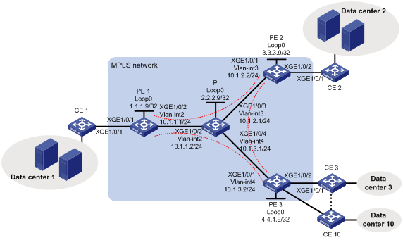
As shown in Figure 3, the MPLS network provides L2VPN services for a company. The company has 10 data centers and will add 15 data centers in the future.
Configure full-mesh VPLS using BGP signaling to allow communication among the data centers at Layer 2.
Analysis
To meet the network requirements, you must perform the following tasks:
· To implement BGP VPLS over the MPLS backbone, you must perform the following tasks:
¡ Establish LDP LSPs on the MPLS backbone as public tunnels to deliver the private data over the MPLS network.
¡ Configure a BGP PW between any two PEs to forward data among the data centers.
¡ Configure service instances and match criteria on the CE-facing interfaces of PEs to identify packets to be transported by VPLS.
· For future expansion of the customer network, set the maximum number of sites in the VPN to 25.
· To implement VLAN isolation among the sites, create VSIs user_a and user_b. Bind VSI user_a to the service instance that matches packets of VLAN 100, and bind VSI user_b to the service instance that matches packets of VLAN 200.
Procedures
1. Configure an IGP on the MPLS backbone to ensure IP connectivity within the backbone:
# On PE 1, configure an IP address for Loopback 0.
<PE1> system-view
[PE1] interface loopback 0
[PE1-LoopBack0] ip address 1.1.1.9 32
[PE1-LoopBack0] quit
# On PE 1, create VLAN 2 and assign Ten-GigabitEthernet 1/0/2 to the VLAN.
[PE1] vlan 2
[PE1-vlan2] port ten-gigabitethernet 1/0/2
[PE1-vlan2] quit
# On PE 1, configure VLAN-interface 2.
[PE1] interface vlan-interface 2
[PE1-Vlan-interface2] ip address 10.1.1.1 24
[PE1-Vlan-interface2] quit
# On PE 1, configure OSPF.
[PE1] ospf
[PE1-ospf-1] area 0
[PE1-ospf-1-area-0.0.0.0] network 10.1.1.0 0.0.0.255
[PE1-ospf-1-area-0.0.0.0] network 1.1.1.9 0.0.0.0
[PE1-ospf-1-area-0.0.0.0] quit
[PE1-ospf-1] quit
# On PE 2, configure an IP address for Loopback 0.
<PE2> system-view
[PE2] interface loopback 0
[PE2-LoopBack0] ip address 3.3.3.9 32
[PE2-LoopBack0] quit
# On PE 2, create VLAN 3 and assign Ten-GigabitEthernet 1/0/1 to the VLAN.
[PE2] vlan 3
[PE2-vlan3] port ten-gigabitethernet 1/0/1
[PE2-vlan3] quit
# On PE 2, configure VLAN-interface 3.
[PE2] interface vlan-interface 3
[PE2-Vlan-interface3] ip address 10.1.2.2 24
[PE2-Vlan-interface3] quit
# On PE 2, configure OSPF.
[PE2] ospf
[PE2-ospf-1] area 0
[PE2-ospf-1-area-0.0.0.0] network 10.1.2.0 0.0.0.255
[PE2-ospf-1-area-0.0.0.0] network 3.3.3.9 0.0.0.0
[PE2-ospf-1-area-0.0.0.0] quit
[PE2-ospf-1] quit
# On PE 3, configure an IP address for Loopback 0.
<PE3> system-view
[PE3] interface loopback 0
[PE3-LoopBack0] ip address 4.4.4.9 32
[PE3-LoopBack0] quit
# On PE 3, create VLAN 4 and assign Ten-GigabitEthernet 1/0/1 to the VLAN.
[PE3] vlan 4
[PE3-vlan4] port ten-gigabitethernet 1/0/1
[PE3-vlan4] quit
# On PE 3, configure VLAN-interface 4.
[PE3] interface vlan-interface 4
[PE3-Vlan-interface4] ip address 10.1.3.2 24
[PE3-Vlan-interface4] quit
# On PE 3, configure OSPF.
[PE3] ospf
[PE3-ospf-1] area 0
[PE3-ospf-1-area-0.0.0.0] network 10.1.3.0 0.0.0.255
[PE3-ospf-1-area-0.0.0.0] network 4.4.4.9 0.0.0.0
[PE3-ospf-1-area-0.0.0.0] quit
[PE3-ospf-1] quit
# On P, configure an IP address for Loopback 0.
<P> system-view
[P] interface loopback 0
[P-LoopBack0] ip address 2.2.2.9 32
[P-LoopBack0] quit
# On P, create VLAN 2 and assign Ten-GigabitEthernet 1/0/2 to the VLAN.
[P] vlan 2
[P-vlan2] port ten-gigabitethernet 1/0/2
[P-vlan2] quit
# On P, configure VLAN-interface 2.
[P] interface vlan-interface 2
[P-Vlan-interface2] ip address 10.1.1.2 24
[P-Vlan-interface2] quit
# On P, create VLAN 3 and assign Ten-GigabitEthernet 1/0/3 to the VLAN.
[P] vlan 3
[P-vlan3] port ten-gigabitethernet 1/0/3
[P-vlan3] quit
# On P, configure VLAN-interface 3.
[P] interface vlan-interface 3
[P-Vlan-interface3] ip address 10.1.2.1 24
[P-Vlan-interface3] quit
# On P, create VLAN 4 and assign Ten-GigabitEthernet 1/0/4 to the VLAN.
[P] vlan 4
[P-vlan4] port ten-gigabitethernet 1/0/4
[P-vlan4] quit
# On P, configure VLAN-interface 4.
[P] interface vlan-interface 4
[P-Vlan-interface4] ip address 10.1.3.1 24
[P-Vlan-interface4] quit
# On P, configure OSPF.
[P] ospf
[P-ospf-1] area 0
[P-ospf-1-area-0.0.0.0] network 10.1.1.0 0.0.0.255
[P-ospf-1-area-0.0.0.0] network 10.1.2.0 0.0.0.255
[P-ospf-1-area-0.0.0.0] network 10.1.3.0 0.0.0.255
[P-ospf-1-area-0.0.0.0] network 2.2.2.9 0.0.0.0
[P-ospf-1-area-0.0.0.0] quit
[P-ospf-1] quit
2. Configure basic MPLS and MPLS LDP on the MPLS backbone to establish LDP LSPs:
# On PE 1, configure an LSR ID.
[PE1] mpls lsr-id 1.1.1.9
# On PE 1, enable LDP globally.
[PE1] mpls ldp
[PE1-ldp] quit
# On PE 1, enable MPLS and LDP on VLAN-interface 2.
[PE1] interface vlan-interface 2
[PE1-Vlan-interface2] mpls enable
[PE1-Vlan-interface2] mpls ldp enable
[PE1-Vlan-interface2] quit
# On PE 2, configure an LSR ID.
[PE2] mpls lsr-id 3.3.3.9
# On PE 2, enable LDP globally.
[PE2] mpls ldp
[PE2-ldp] quit
# On PE 2, enable MPLS and LDP on VLAN-interface 3.
[PE2] interface vlan-interface 3
[PE2-Vlan-interface3] mpls enable
[PE2-Vlan-interface3] mpls ldp enable
[PE2-Vlan-interface3] quit
# On PE 3, configure an LSR ID.
[PE3] mpls lsr-id 4.4.4.9
# On PE 3, enable LDP globally.
[PE3] mpls ldp
[PE3-ldp] quit
# On PE 3, enable MPLS and LDP on VLAN-interface 4.
[PE3] interface vlan-interface 4
[PE3-Vlan-interface4] mpls enable
[PE3-Vlan-interface4] mpls ldp enable
[PE3-Vlan-interface4] quit
# On P, configure an LSR ID.
[P] mpls lsr-id 2.2.2.9
# On P, enable LDP globally.
[P] mpls ldp
[P-ldp] quit
# On P, enable MPLS and LDP on VLAN-interface 2.
[P] interface vlan-interface 2
[P-Vlan-interface2] mpls enable
[P-Vlan-interface2] mpls ldp enable
[P-Vlan-interface2] quit
# On P, enable MPLS and LDP on VLAN-interface 3.
[P] interface vlan-interface 3
[P-Vlan-interface3] mpls enable
[P-Vlan-interface3] mpls ldp enable
[P-Vlan-interface3] quit
# On P, enable MPLS and LDP on VLAN-interface 4.
[P] interface vlan-interface 4
[P-Vlan-interface4] mpls enable
[P-Vlan-interface4] mpls ldp enable
[P-Vlan-interface4] quit
3. Configure VSIs and BGP PWs:
# On PE 1, establish IBGP connections to PE 2 and PE 3.
[PE1] bgp 100
[PE1-bgp] peer 3.3.3.9 as-number 100
[PE1-bgp] peer 3.3.3.9 connect-interface loopback 0
[PE1-bgp] peer 4.4.4.9 as-number 100
[PE1-bgp] peer 4.4.4.9 connect-interface loopback 0
# On PE 1, enable BGP to exchange L2VPN information with the peers.
[PE1-bgp] address-family l2vpn
[PE1-bgp-l2vpn] peer 3.3.3.9 enable
[PE1-bgp-l2vpn] peer 4.4.4.9 enable
[PE1-bgp-l2vpn] quit
[PE1-bgp] quit
# On PE 1, enable MPLS L2VPN globally.
[PE1] l2vpn enable
# On PE 1, create VSI user_a and enable the VSI to automatically discover neighbors through BGP.
[PE1] vsi user_a
[PE1-vsi-user_a] auto-discovery bgp
# On PE 1, configure an RD and route targets for the VSI.
[PE1-vsi-user_a-auto] route-distinguisher 100:1
[PE1-vsi-user_a-auto] vpn-target 111:1
# On PE 1, use BGP to establish a PW to a remote PE discovered by BGP.
[PE1-vsi-user_a-auto] signaling-protocol bgp
# On PE 1, set the site number in the VSI to 1 and the maximum number of sites in the VSI to 25.
[PE1-vsi-user_a-auto-bgp] site 1 range 25
[PE1-vsi-user_a-auto-bgp] quit
[PE1-vsi-user_a-auto] quit
[PE1-vsi-user_a] quit
# On PE 1, create VSI user_b and enable the VSI to automatically discover neighbors through BGP.
[PE1] vsi user_b
[PE1-vsi-user_b] auto-discovery bgp
# On PE 1, configure an RD and route targets for the VSI.
[PE1-vsi-user_b-auto] route-distinguisher 200:1
[PE1-vsi-user_b-auto] vpn-target 222:1
# On PE 1, use BGP to establish a PW to a remote PE discovered by BGP.
[PE1-vsi-user_b-auto] signaling-protocol bgp
# On PE 1, set the site number in the VSI to 1 and the maximum number of sites in the VSI to 25.
[PE1-vsi-user_b-auto-bgp] site 1 range 25
[PE1-vsi-user_b-auto-bgp] quit
[PE1-vsi-user_b-auto] quit
[PE1-vsi-user_b] quit
# On PE 2, establish IBGP connections to PE 1 and PE 3.
[PE2] bgp 100
[PE2-bgp] peer 1.1.1.9 as-number 100
[PE2-bgp] peer 1.1.1.9 connect-interface loopback 0
[PE2-bgp] peer 4.4.4.9 as-number 100
[PE2-bgp] peer 4.4.4.9 connect-interface loopback 0
# On PE 2, enable BGP to exchange L2VPN information with the peers.
[PE2-bgp] address-family l2vpn
[PE2-bgp-l2vpn] peer 1.1.1.9 enable
[PE2-bgp-l2vpn] peer 4.4.4.9 enable
[PE2-bgp-l2vpn] quit
[PE2-bgp] quit
# On PE 2, enable MPLS L2VPN globally.
[PE2] l2vpn enable
# On PE 2, create VSI user_a and enable the VSI to automatically discover neighbors through BGP.
[PE2] vsi user_a
[PE2-vsi-user_a] auto-discovery bgp
# On PE 2, configure an RD and route targets for the VSI.
[PE2-vsi-user_a-auto] route-distinguisher 100:1
[PE2-vsi-user_a-auto] vpn-target 111:1
# On PE 2, use BGP to establish a PW to a remote PE discovered by BGP.
[PE2-vsi-user_a-auto] signaling-protocol bgp
# On PE 2, set the site number in the VSI to 2 and the maximum number of sites in the VSI to 25.
[PE2-vsi-user_a-auto-bgp] site 2 range 25
[PE2-vsi-user_a-auto-bgp] quit
[PE2-vsi-user_a-auto] quit
[PE2-vsi-user_a] quit
# On PE 2, create VSI user_b and enable the VSI to automatically discover neighbors through BGP.
[PE2] vsi user_b
[PE2-vsi-user_b] auto-discovery bgp
# On PE 2, configure an RD and route targets for the VSI.
[PE2-vsi-user_b-auto] route-distinguisher 200:1
[PE2-vsi-user_b-auto] vpn-target 222:1
# On PE 2, use BGP to establish a PW to a remote PE discovered by BGP.
[PE2-vsi-user_b-auto] signaling-protocol bgp
# On PE 2, set the site number in the VSI to 2 and the maximum number of sites in the VSI to 25.
[PE2-vsi-user_b-auto-bgp] site 2 range 25
[PE2-vsi-user_b-auto-bgp] quit
[PE2-vsi-user_b-auto] quit
[PE2-vsi-user_b] quit
# On PE 3, establish IBGP connections to PE 1 and PE 2.
[PE3] bgp 100
[PE3-bgp] peer 1.1.1.9 as-number 100
[PE3-bgp] peer 1.1.1.9 connect-interface loopback 0
[PE3-bgp] peer 3.3.3.9 as-number 100
[PE3-bgp] peer 3.3.3.9 connect-interface loopback 0
# On PE 3, enable BGP to exchange L2VPN information with the peers.
[PE3-bgp] address-family l2vpn
[PE3-bgp-l2vpn] peer 1.1.1.9 enable
[PE3-bgp-l2vpn] peer 3.3.3.9 enable
[PE3-bgp-l2vpn] quit
[PE3-bgp] quit
# On PE 3, enable MPLS L2VPN globally.
[PE3] l2vpn enable
# On PE 3, create VSI user_a and enable the VSI to automatically discover neighbors through BGP.
[PE3] vsi user_a
[PE3-vsi-user_a] auto-discovery bgp
# On PE 3, configure an RD and route targets for the VSI.
[PE3-vsi-user_a-auto] route-distinguisher 100:1
[PE3-vsi-user_a-auto] vpn-target 111:1
# On PE 3, use BGP to establish a PW to a remote PE discovered by BGP.
[PE3-vsi-user_a-auto] signaling-protocol bgp
# On PE 3, set the site number in the VSI to 3 and the maximum number of sites in the VSI to 25.
[PE3-vsi-user_a-auto-bgp] site 3 range 25
[PE3-vsi-user_a-auto-bgp] quit
[PE3-vsi-user_a-auto] quit
[PE3-vsi-user_a] quit
# On PE 3, create VSI user_b and enable the VSI to automatically discover neighbors through BGP.
[PE3] vsi user_b
[PE3-vsi-user_b] auto-discovery bgp
# On PE 3, configure an RD and route targets for the VSI.
[PE3-vsi-user_b-auto] route-distinguisher 200:1
[PE3-vsi-user_b-auto] vpn-target 222:1
# On PE 3, use BGP to establish a PW to a remote PE discovered by BGP.
[PE3-vsi-user_b-auto] signaling-protocol bgp
# On PE 3, set the site number in the VSI to 3 and the maximum number of sites in the VSI to 25.
[PE3-vsi-user_b-auto-bgp] site 3 range 25
[PE3-vsi-user_b-auto-bgp] quit
[PE3-vsi-user_b-auto] quit
[PE3-vsi-user_b] quit
4. Configure service instances for different VLANs and bind the service instances to VSIs:
# On PE 1, create service instance 100 on Ten-GigabitEthernet 1/0/1 to match packets of VLAN 100, and bind the service instance to VSI user_a.
[PE1] interface ten-gigabitethernet 1/0/1
[PE1-Ten-GigabitEthernet1/0/1] service-instance 100
[PE1-Ten-GigabitEthernet1/0/1-srv100] encapsulation s-vid 100
[PE1-Ten-GigabitEthernet1/0/1-srv100] xconnect vsi user_a
[PE1-Ten-GigabitEthernet1/0/1-srv100] quit
# On PE 1, create service instance 200 on Ten-GigabitEthernet 1/0/1 to match packets of VLAN 200, and bind the service instance to VSI user_b.
[PE1-Ten-GigabitEthernet1/0/1] service-instance 200
[PE1-Ten-GigabitEthernet1/0/1-srv200] encapsulation s-vid 200
[PE1-Ten-GigabitEthernet1/0/1-srv200] xconnect vsi user_b
[PE1-Ten-GigabitEthernet1/0/1-srv200] quit
[PE1-Ten-GigabitEthernet1/0/1] quit
# On PE 2, create service instance 100 on Ten-GigabitEthernet 1/0/2 to match packets of VLAN 100, and bind the service instance to VSI user_a.
[PE2] interface ten-gigabitethernet 1/0/2
[PE2-Ten-GigabitEthernet1/0/2] service-instance 100
[PE2-Ten-GigabitEthernet1/0/2-srv100] encapsulation s-vid 100
[PE2-Ten-GigabitEthernet1/0/2-srv100] xconnect vsi user_a
[PE2-Ten-GigabitEthernet1/0/2-srv100] quit
# On PE 2, create service instance 200 on Ten-GigabitEthernet 1/0/2 to match packets of VLAN 200, and bind the service instance to VSI user_b.
[PE2-Ten-GigabitEthernet1/0/2] service-instance 200
[PE2-Ten-GigabitEthernet1/0/2-srv200] encapsulation s-vid 200
[PE2-Ten-GigabitEthernet1/0/2-srv200] xconnect vsi user_b
[PE2-Ten-GigabitEthernet1/0/2-srv200] quit
[PE2-Ten-GigabitEthernet1/0/2] quit
# On PE 3, create service instance 100 on Ten-GigabitEthernet 1/0/2 to match packets of VLAN 100, and bind the service instance to VSI user_a.
[PE3] interface ten-gigabitethernet 1/0/2
[PE3-Ten-GigabitEthernet1/0/2] service-instance 100
[PE3-Ten-GigabitEthernet1/0/2-srv100] encapsulation s-vid 100
[PE3-Ten-GigabitEthernet1/0/2-srv100] xconnect vsi user_a
[PE3-Ten-GigabitEthernet1/0/2-srv100] quit
# On PE 3, create service instance 200 on Ten-GigabitEthernet 1/0/2 to match packets of VLAN 200, and bind the service instance to VSI user_b.
[PE3-Ten-GigabitEthernet1/0/2] service-instance 200
[PE3-Ten-GigabitEthernet1/0/2-srv200] encapsulation s-vid 200
[PE3-Ten-GigabitEthernet1/0/2-srv200] xconnect vsi user_b
[PE3-Ten-GigabitEthernet1/0/2-srv200] quit
[PE3-Ten-GigabitEthernet1/0/2] quit
# On PE 3, configure other CE-facing interfaces in the same way that Ten-GigabitEthernet 1/0/2 is configured. (Details not shown.)
5. Allow CE access to PEs:
# On CE 1, configure the interface connected to the PE to permit tagged packets from the customer VLANs.
<CE1> system-view
[CE1] vlan 100
[CE1-vlan100] quit
[CE1] vlan 200
[CE1-vlan200] quit
[CE1] interface ten-gigabitethernet 1/0/1
[CE1-Ten-GigabitEthernet1/0/1] port link-type trunk
[CE1-Ten-GigabitEthernet1/0/1] port trunk permit vlan 100 200
# Configure other CEs in the same way that CE 1 is configured. (Details not shown.)
Verifying the configuration
# Verify that LDP LSPs have been established on each switch in the MPLS network. This example uses PE 1.
[PE1] display mpls ldp lsp
Status Flags: * - stale, L - liberal
Statistics:
FECs: 4 Ingress LSPs: 3 Transit LSPs: 3 Egress LSPs: 1
FEC In/Out Label Nexthop OutInterface
1.1.1.9/32 3/-
-/1151(L)
2.2.2.9/32 -/3 10.1.1.2 Vlan2
1151/3 10.1.1.2 Vlan2
3.3.3.9/32 -/1150 10.1.1.2 Vlan2
1150/1150 10.1.1.2 Vlan2
4.4.4.9/32 -/1149 10.1.1.2 Vlan2
1149/1149 10.1.1.2 Vlan2
# Verify BGP PWs in up state have been established on each PE. This example uses PE 1.
[PE1] display l2vpn pw
Flags: M - main, B - backup, H - hub link, S - spoke link, N - no split horizon
Total number of PWs: 2, 2 up, 0 blocked, 0 down, 0 defect
VSI Name: user_a
Peer PW ID/Rmt Site In/Out Label Proto Flag Link ID State
3.3.3.9 2 131074/131073 BGP M 257 Up
4.4.4.9 3 131075/131073 BGP M 258 Up
Peer PW ID/Rmt Site In/Out Label Proto Flag Link ID State
3.3.3.9 2 131071/131070 BGP M 257 Up
4.4.4.9 3 131072/131070 BGP M 258 Up
# Verify that hosts in the same VLAN but different sites can ping each other. (Details not shown.)
Configuration files
· PE 1:
#
ospf 1
area 0.0.0.0
network 1.1.1.9 0.0.0.0
network 10.1.1.0 0.0.0.255
#
mpls lsr-id 1.1.1.9
#
vlan 2
#
mpls ldp
#
l2vpn enable
#
vsi user_a
auto-discovery bgp
route-distinguisher 100:1
vpn-target 111:1 export-extcommunity
vpn-target 111:1 import-extcommunity
signaling-protocol bgp
site 1 range 25 default-offset 0
#
vsi user_b
auto-discovery bgp
route-distinguisher 200:1
vpn-target 222:1 export-extcommunity
vpn-target 222:1 import-extcommunity
signaling-protocol bgp
site 1 range 25 default-offset 0
#
interface LoopBack0
ip address 1.1.1.9 255.255.255.255
#
interface Vlan-interface2
ip address 10.1.1.1 255.255.255.0
mpls enable
mpls ldp enable
#
interface Ten-GigabitEthernet1/0/1
port link-mode bridge
service-instance 100
encapsulation s-vid 100
xconnect vsi user_a
service-instance 200
encapsulation s-vid 200
xconnect vsi user_b
#
interface Ten-GigabitEthernet1/0/2
port link-mode bridge
port access vlan 2
#
bgp 100
peer 3.3.3.9 as-number 100
peer 3.3.3.9 connect-interface LoopBack0
peer 4.4.4.9 as-number 100
peer 4.4.4.9 connect-interface LoopBack0
#
address-family l2vpn
peer 3.3.3.9 enable
peer 4.4.4.9 enable
#
· PE 2:
#
ospf 1
area 0.0.0.0
network 10.1.2.0 0.0.0.255
network 3.3.3.9 0.0.0.0
#
mpls lsr-id 3.3.3.9
#
vlan 3
#
mpls ldp
#
l2vpn enable
#
vsi user_a
auto-discovery bgp
route-distinguisher 100:1
vpn-target 111:1 export-extcommunity
vpn-target 111:1 import-extcommunity
signaling-protocol bgp
site 2 range 25 default-offset 0
#
vsi user_b
auto-discovery bgp
route-distinguisher 200:1
vpn-target 222:1 export-extcommunity
vpn-target 222:1 import-extcommunity
signaling-protocol bgp
site 2 range 25 default-offset 0
#
interface LoopBack0
ip address 3.3.3.9 255.255.255.255
#
interface Vlan-interface3
ip address 10.1.2.2 255.255.255.0
mpls enable
mpls ldp enable
#
interface Ten-GigabitEthernet1/0/1
port link-mode bridge
port access vlan 3
#
interface Ten-GigabitEthernet1/0/2
port link-mode bridge
service-instance 100
encapsulation s-vid 100
xconnect vsi user_a
service-instance 200
encapsulation s-vid 200
xconnect vsi user_b
#
bgp 100
peer 1.1.1.9 as-number 100
peer 1.1.1.9 connect-interface LoopBack0
peer 4.4.4.9 as-number 100
peer 4.4.4.9 connect-interface LoopBack0
#
address-family l2vpn
peer 1.1.1.9 enable
peer 4.4.4.9 enable
#
· PE 3:
#
ospf 1
area 0.0.0.0
network 10.1.3.0 0.0.0.255
network 4.4.4.9 0.0.0.0
#
mpls lsr-id 4.4.4.9
#
vlan 4
#
mpls ldp
#
l2vpn enable
#
vsi user_a
auto-discovery bgp
route-distinguisher 100:1
vpn-target 111:1 export-extcommunity
vpn-target 111:1 import-extcommunity
signaling-protocol bgp
site 3 range 25 default-offset 0
#
vsi user_b
auto-discovery bgp
route-distinguisher 200:1
vpn-target 222:1 export-extcommunity
vpn-target 222:1 import-extcommunity
signaling-protocol bgp
site 3 range 25 default-offset 0
#
interface LoopBack0
ip address 4.4.4.9 255.255.255.255
#
interface Vlan-interface4
ip address 10.1.3.2 255.255.255.0
mpls enable
mpls ldp enable
#
interface Ten-GigabitEthernet1/0/1
port link-mode bridge
port access vlan 4
#
interface Ten-GigabitEthernet1/0/2
port link-mode bridge
service-instance 100
encapsulation s-vid 100
xconnect vsi user_a
service-instance 200
encapsulation s-vid 200
xconnect vsi user_b
#
bgp 100
peer 1.1.1.9 as-number 100
peer 1.1.1.9 connect-interface LoopBack0
peer 3.3.3.9 as-number 100
peer 3.3.3.9 connect-interface LoopBack0
#
address-family l2vpn
peer 1.1.1.9 enable
peer 3.3.3.9 enable
#
· P:
#
ospf 1
area 0.0.0.0
network 10.1.1.0 0.0.0.255
network 10.1.2.0 0.0.0.255
network 10.1.3.0 0.0.0.255
network 2.2.2.9 0.0.0.0
#
mpls lsr-id 2.2.2.9
#
vlan 2 to 4
#
mpls ldp
#
interface LoopBack0
ip address 2.2.2.9 255.255.255.255
#
interface Vlan-interface2
ip address 10.1.1.2 255.255.255.0
mpls enable
mpls ldp enable
#
interface Vlan-interface3
ip address 10.1.2.1 255.255.255.0
mpls enable
mpls ldp enable
#
interface Vlan-interface4
ip address 10.1.3.1 255.255.255.0
mpls enable
mpls ldp enable
#
interface Ten-GigabitEthernet1/0/2
port link-mode bridge
port access vlan 2
#
interface Ten-GigabitEthernet1/0/3
port link-mode bridge
port access vlan 3
#
interface Ten-GigabitEthernet1/0/4
port link-mode bridge
port access vlan 4
#
· CE 1 through CE 10:
#
vlan 100
#
vlan 200
#
interface Ten-GigabitEthernet1/0/1
port link-mode bridge
port link-type trunk
port trunk permit vlan 100 200
#
Example: Configuring H-VPLS with LSP access
Network configuration
As shown in Figure 4, a customer's branches are connected to the MPLS backbone through UPEs that support MPLS L2VPN.
Configure H-VPLS to allow communication among the branches at Layer 2.
· Connect the UPEs to the NPEs through LSPs.
· Configure UPE dual homing to achieve redundancy.

Table 1 Interface and IP address assignment
|
Device |
Interface |
IP address |
Device |
Interface |
IP address |
|
UPE 1 |
Loop0 |
11.1.1.1/32 |
UPE 2 |
Loop0 |
14.1.1.1/32 |
|
|
Vlan-int10 |
11.1.2.1/24 |
|
Vlan-int12 |
20.1.1.1/24 |
|
|
Vlan-int11 |
11.1.3.1/24 |
|
Vlan-int13 |
20.1.2.1/24 |
|
NPE 1 |
Loop0 |
1.1.1.1/32 |
NPE 3 |
Loop0 |
3.3.3.3/32 |
|
|
Vlan-int10 |
11.1.2.2/24 |
|
Vlan-int13 |
20.1.2.2/24 |
|
NPE 2 |
Loop0 |
2.2.2.2/32 |
NPE 4 |
Loop0 |
4.4.4.4/32 |
|
|
Vlan-int11 |
11.1.3.2/24 |
|
Vlan-int12 |
20.1.1.2/24 |
Analysis
To meet the network requirements, you must perform the following tasks:
· To negotiate inner labels, perform the following tasks:
¡ Configure each UPE and all the NPEs connected to the UPE as LDP peers.
¡ Configure any two NPEs as LDP peers.
· To achieve NPE redundancy, configure the NPEs that are connected to each UPE as primary and backup peers.
· To identify packets to be transported by VPLS, configure service instances and match criteria on the CE-facing interfaces of UPEs.
· To implement VLAN isolation among the sites, create VSIs user_a and user_b. Bind VSI user_a to the service instance that matches packets of VLAN 100, and bind VSI user_b to the service instance that matches packets of VLAN 200.
Procedures
Configuring basic settings
# Create interfaces on UPEs and NPEs and configure IP addresses for the interfaces as shown in Figure 4. (Details not shown.)
# Configure an IGP on the MPLS backbone to ensure that the interfaces of NPEs and UPEs are reachable to each other. (Details not shown.)
# Configure basic MPLS and MPLS LDP on the MPLS backbone to establish LDP LSPs. (Details not shown.)
# Configure the ports of CEs connecting the UPEs as trunk ports that permit tagged packets from VLAN 100 and VLAN 200. (Details not shown.)
Configuring UPE 1
# Configure basic MPLS.
<UPE1> system-view
[UPE1] mpls lsr-id 11.1.1.1
[UPE1] mpls ldp
[UPE1-ldp] quit
# Configure basic MPLS on the interface connected to NPE 1.
[UPE1] interface vlan-interface 10
[UPE1-Vlan-interface10] mpls enable
[UPE1-Vlan-interface10] mpls ldp enable
[UPE1-Vlan-interface10] quit
# Configure basic MPLS on the interface connected to NPE 2.
[UPE1] interface vlan-interface 11
[UPE1-Vlan-interface11] mpls enable
[UPE1-Vlan-interface11] mpls ldp enable
[UPE1-Vlan-interface11] quit
# Enable MPLS L2VPN.
[UPE1] l2vpn enable
# Create VSI user_a and configure the VSI to use LDP as the PW signaling protocol.
[UPE1] vsi user_a
[UPE1-vsi-user_a] pwsignaling ldp
# Specify the switchover wait time as 120 seconds. When the primary PW recovers, the device waits for 120 seconds before it switches traffic from the backup PW to the primary PW.
[UPE1-vsi-user_a-ldp] revertive wtr 120
# Establish the primary PW (the PW to NPE 1) and the backup PW (the PW to NPE 2).
[UPE1-vsi-user_a-ldp] peer 1.1.1.1 pw-id 500
[UPE1-vsi-user_a-ldp-1.1.1.1-500] backup-peer 2.2.2.2 pw-id 500
[UPE1-vsi-user_a-ldp-1.1.1.1-500-backup] quit
[UPE1-vsi-user_a-ldp-1.1.1.1-500] quit
[UPE1-vsi-user_a-ldp] quit
[UPE1-vsi-user_a] quit
# Create VSI user_b and configure the VSI to use LDP as the PW signaling protocol.
[UPE1] vsi user_b
[UPE1-vsi-user_b] pwsignaling ldp
# Specify the switchover wait time as 120 seconds. When the primary PW recovers, the device waits for 120 seconds before it switches traffic from the backup PW to the primary PW.
[UPE1-vsi-user_b-ldp] revertive wtr 120
# Establish the primary PW (the PW to NPE 1) and the backup PW (the PW to NPE 2).
[UPE1-vsi-user_b-ldp] peer 1.1.1.1 pw-id 600
[UPE1-vsi-user_b-ldp-1.1.1.1-600] backup-peer 2.2.2.2 pw-id 600
[UPE1-vsi-user_b-ldp-1.1.1.1-600-backup] quit
[UPE1-vsi-user_b-ldp-1.1.1.1-600] quit
[UPE1-vsi-user_b-ldp] quit
[UPE1-vsi-user_b] quit
# Create service instance 1000 on Ten-GigabitEthernet 1/0/1 (the interface connected to Site A) to match packets from VLAN 100, and bind the service instance to VSI user_a.
[UPE1] interface ten-gigabitethernet 1/0/1
[UPE1-Ten-GigabitEthernet1/0/1] service-instance 1000
[UPE1-Ten-GigabitEthernet1/0/1-srv1000] encapsulation s-vid 100
[UPE1-Ten-GigabitEthernet1/0/1-srv1000] xconnect vsi user_a
[UPE1-Ten-GigabitEthernet1/0/1-srv1000] quit
# Create service instance 2000 on Ten-GigabitEthernet 1/0/1 to match packets from VLAN 200, and bind the service instance to VSI user_b.
[UPE1-Ten-GigabitEthernet1/0/1] service-instance 2000
[UPE1-Ten-GigabitEthernet1/0/1-srv2000] encapsulation s-vid 200
[UPE1-Ten-GigabitEthernet1/0/1-srv2000] xconnect vsi user_b
[UPE1-Ten-GigabitEthernet1/0/1-srv2000] quit
# Create service instance 1000 on Ten-GigabitEthernet 1/0/2 (the interface connected to Site B) to match packets from VLAN 100, and bind the service instance to VSI user_a.
[UPE1] interface ten-gigabitethernet 1/0/2
[UPE1-Ten-GigabitEthernet1/0/2] service-instance 1000
[UPE1-Ten-GigabitEthernet1/0/2-srv1000] encapsulation s-vid 100
[UPE1-Ten-GigabitEthernet1/0/2-srv1000] xconnect vsi user_a
[UPE1-Ten-GigabitEthernet1/0/2-srv1000] quit
# Create service instance 2000 on Ten-GigabitEthernet 1/0/2 to match packets from VLAN 200, and bind the service instance to VSI user_b.
[UPE1-Ten-GigabitEthernet1/0/2] service-instance 2000
[UPE1-Ten-GigabitEthernet1/0/2-srv2000] encapsulation s-vid 200
[UPE1-Ten-GigabitEthernet1/0/2-srv2000] xconnect vsi user_b
[UPE1-Ten-GigabitEthernet1/0/2-srv2000] quit
Configuring NPE 1
# Configure basic MPLS on the interface connected to UPE 1.
<NPE1> system-view
[NPE1] interface vlan-interface 10
[NPE1-Vlan-interface10] mpls enable
[NPE1-Vlan-interface10] mpls ldp enable
[NPE1-Vlan-interface10] quit
# Enable MPLS L2VPN.
[NPE1] l2vpn enable
# Create VSI user_a and configure the VSI to use LDP as the PW signaling protocol.
[NPE1] vsi user_a
[NPE1-vsi-user_a] pwsignaling ldp
# Establish a PW to UPE 1.
[NPE1-vsi-user_a-ldp] peer 11.1.1.1 pw-id 500 no-split-horizon
[NPE1-vsi-user_a-ldp-11.1.1.1-500] quit
# Establish a PW to NPE 2.
[NPE1-vsi-user_a-ldp] peer 2.2.2.2 pw-id 500
[NPE1-vsi-user_a-ldp-2.2.2.2-500] quit
# Establish a PW to NPE 3.
[NPE1-vsi-user_a-ldp] peer 3.3.3.3 pw-id 500
[NPE1-vsi-user_a-ldp-3.3.3.3-500] quit
# Establish a PW to NPE 4.
[NPE1-vsi-user_a-ldp] peer 4.4.4.4 pw-id 500
[NPE1-vsi-user_a-ldp-4.4.4.4-500] quit
[NPE1-vsi-user_a-ldp] quit
[NPE1-vsi-user_a] quit
# Create VSI user_b and configure the VSI to use LDP as the PW signaling protocol.
[NPE1] vsi user_b
[NPE1-vsi-user_b] pwsignaling ldp
# Establish a PW to UPE 1.
[NPE1-vsi-user_b-ldp] peer 11.1.1.1 pw-id 600 no-split-horizon
[NPE1-vsi-user_b-ldp-11.1.1.1-500] quit
# Establish a PW to NPE 2.
[NPE1-vsi-user_b-ldp] peer 2.2.2.2 pw-id 600
[NPE1-vsi-user_b-ldp-2.2.2.2-600] quit
# Establish a PW to NPE 3.
[NPE1-vsi-user_b-ldp] peer 3.3.3.3 pw-id 600
[NPE1-vsi-user_b-ldp-3.3.3.3-600] quit
# Establish a PW to NPE 4.
[NPE1-vsi-user_b-ldp] peer 4.4.4.4 pw-id 600
[NPE1-vsi-user_b-ldp-4.4.4.4-600] quit
[NPE1-vsi-user_b-ldp] quit
[NPE1-vsi-user_b] quit
Configuring NPE 2
# Configure NPE 2 in the same way that NPE 1 is configured. (Details not shown.)
Configuring UPE 2
# Configure basic MPLS.
<UPE2> system-view
[UPE2] mpls lsr-id 14.1.1.1
[UPE2] mpls ldp
[UPE2-ldp] quit
# Configure basic MPLS on the interface connected to NPE 3.
[UPE2] interface vlan-interface 13
[UPE2-Vlan-interface13] mpls enable
[UPE2-Vlan-interface13] mpls ldp enable
[UPE2-Vlan-interface13] quit
# Configure basic MPLS on the interface connected to NPE 4.
[UPE2] interface vlan-interface 12
[UPE2-Vlan-interface12] mpls enable
[UPE2-Vlan-interface12] mpls ldp enable
[UPE2-Vlan-interface12] quit
# Enable MPLS L2VPN.
[UPE2] l2vpn enable
# Create VSI user_a and configure the VSI to use LDP as the PW signaling protocol.
[UPE2] vsi user_a
[UPE2-vsi-user_a] pwsignaling ldp
# Specify the switchover wait time as 120 seconds. When the primary PW recovers, the device waits for 120 seconds before it switches traffic from the backup PW to the primary PW.
[UPE2-vsi-user_a-ldp] revertive wtr 120
# Establish the primary PW (the PW to NPE 3) and the backup PW (the PW to NPE 4).
[UPE2-vsi-user_a-ldp] peer 3.3.3.3 pw-id 500
[UPE2-vsi-user_a-ldp-3.3.3.3-500] backup-peer 4.4.4.4 pw-id 500
[UPE2-vsi-user_a-ldp-3.3.3.3-500-backup] quit
[UPE2-vsi-user_a-ldp-3.3.3.3-500] quit
[UPE2-vsi-user_a-ldp] quit
[UPE2-vsi-user_a] quit
# Create VSI user_b and configure the VSI to use LDP as the PW signaling protocol.
[UPE2] vsi user_b
[UPE2-vsi-user_b] pwsignaling ldp
# Specify the switchover wait time as 120 seconds. When the primary PW recovers, the device waits for 120 seconds before it switches traffic from the backup PW to the primary PW.
[UPE2-vsi-user_b-ldp] revertive wtr 120
# Establish the primary PW (the PW to NPE 3) and the backup PW (the PW to NPE 4).
[UPE2-vsi-user_b-ldp] peer 3.3.3.3 pw-id 600
[UPE2-vsi-user_b-ldp-3.3.3.3-600] backup-peer 4.4.4.4 pw-id 600
[UPE2-vsi-user_b-ldp-3.3.3.3-600-backup] quit
[UPE2-vsi-user_b-ldp-3.3.3.3-600] quit
[UPE2-vsi-user_b-ldp] quit
[UPE2-vsi-user_b] quit
# Create service instance 1000 on Ten-GigabitEthernet 1/0/1 (the interface connected to Site E) to match packets from VLAN 100, and bind the service instance to VSI user_a.
[UPE2] interface ten-gigabitethernet 1/0/1
[UPE2-Ten-GigabitEthernet1/0/1] service-instance 1000
[UPE2-Ten-GigabitEthernet1/0/1-srv1000] encapsulation s-vid 100
[UPE2-Ten-GigabitEthernet1/0/1-srv1000] xconnect vsi user_a
[UPE2-Ten-GigabitEthernet1/0/1-srv1000] quit
# Create service instance 2000 on Ten-GigabitEthernet 1/0/1 to match packets from VLAN 200, and bind the service instance to VSI user_b.
[UPE2-Ten-GigabitEthernet1/0/1] service-instance 2000
[UPE2-Ten-GigabitEthernet1/0/1-srv2000] encapsulation s-vid 200
[UPE2-Ten-GigabitEthernet1/0/1-srv2000] xconnect vsi user_b
[UPE2-Ten-GigabitEthernet1/0/1-srv2000] quit
Configuring NPE 3
# Configure basic MPLS on the interface connected to UPE 2.
[NPE3] interface vlan-interface 13
[NPE3-Vlan-interface13] mpls enable
[NPE3-Vlan-interface13] mpls ldp enable
[NPE3-Vlan-interface13] quit
# Enable MPLS L2VPN.
[NPE3] l2vpn enable
# Create VSI user_a and configure the VSI to use LDP as the PW signaling protocol.
[NPE3] vsi user_a
[NPE3-vsi-user_a] pwsignaling ldp
# Establish a PW to UPE 2.
[NPE3-vsi-user_a-ldp] peer 14.1.1.1 pw-id 500 no-split-horizon
[NPE3-vsi-user_a-ldp-14.1.1.1-500] quit
# Establish a PW to NPE 1.
[NPE3-vsi-user_a-ldp] peer 1.1.1.1 pw-id 500
[NPE3-vsi-user_a-ldp-1.1.1.1-500] quit
# Establish a PW to NPE 2.
[NPE3-vsi-user_a-ldp] peer 2.2.2.2 pw-id 500
[NPE3-vsi-user_a-ldp-2.2.2.2-500] quit
# Establish a PW to NPE 4.
[NPE3-vsi-user_a-ldp] peer 4.4.4.4 pw-id 500
[NPE3-vsi-user_a-ldp-4.4.4.4-500] quit
[NPE3-vsi-user_a-ldp] quit
[NPE3-vsi-user_a] quit
# Create VSI user_b and configure the VSI to use LDP as the PW signaling protocol.
[NPE3] vsi user_b
[NPE3-vsi-user_b] pwsignaling ldp
# Establish a PW to UPE 2.
[NPE3-vsi-user_b-ldp] peer 14.1.1.1 pw-id 600 no-split-horizon
[NPE3-vsi-user_b-ldp-14.1.1.1-600] quit
# Establish a PW to NPE 1.
[NPE3-vsi-user_b-ldp] peer 1.1.1.1 pw-id 600
[NPE3-vsi-user_b-ldp-1.1.1.1-600] quit
# Establish a PW to NPE 2.
[NPE3-vsi-user_b-ldp] peer 2.2.2.2 pw-id 600
[NPE3-vsi-user_b-ldp-2.2.2.2-600] quit
# Establish a PW to NPE 4.
[NPE3-vsi-user_b-ldp] peer 4.4.4.4 pw-id 600
[NPE3-vsi-user_b-ldp-4.4.4.4-600] quit
[NPE3-vsi-user_b-ldp] quit
[NPE3-vsi-user_b] quit
Configuring NPE 4
# Configure NPE 4 in the same way that NPE 3 is configured. (Details not shown.)
Verifying the configuration
# Verify that LDP PWs in up state have been established on each UPE. This example uses UPE 1.
[UPE1] display l2vpn pw
Flags: M - main, B - backup, H - hub link, S - spoke link, N - no split horizon
Total number of PWs: 4, 4 up, 0 blocked, 0 down, 0 defect
VSI Name: user_a
Peer PW ID/Rmt Site In/Out Label Proto Flag Link ID State
1.1.1.1 500 131199/131199 LDP M 256 Up
2.2.2.2 500 131198/131199 LDP B 257 Blocked
VSI Name: user_b
Peer PW ID/Rmt Site In/Out Label Proto Flag Link ID State
1.1.1.1 600 131195/131195 LDP M 256 Up
2.2.2.2 600 131194/131195 LDP B 257 Blocked
# Verify that LDP PWs in up state have been established on each NPE. This example uses NPE 1.
[NPE1] display l2vpn pw
Flags: M - main, B - backup, H - hub link, S - spoke link, N - no split horizon
Total number of PWs: 4, 4 up, 0 blocked, 0 down, 0 defect
VSI Name: user_a
Peer PW ID/Rmt Site In/Out Label Proto Flag Link ID State
2.2.2.2 500 131199/131199 LDP M 256 Up
3.3.3.3 500 131198/131198 LDP M 257 Up
4.4.4.4 500 131197/131197 LDP M 258 Up
11.1.1.1 500 131196/131196 LDP MN 259 Up
VSI Name: user_b
Peer PW ID/Rmt Site In/Out Label Proto Flag Link ID State
2.2.2.2 600 131195/131195 LDP M 256 Up
3.3.3.3 600 131194/131194 LDP M 257 Up
4.4.4.4 600 131193/131193 LDP M 258 Up
11.1.1.1 600 131192/131192 LDP MN 259 Up
# Verify that hosts in the same VLAN but different sites can ping each other. (Details not shown.)
Configuration files
The following lists only the H-VPLS-related configuration files. CE configuration and PE routing configuration are not shown.
· UPE 1:
#
mpls lsr-id 11.1.1.1
#
vlan 10 to 11
#
mpls ldp
#
l2vpn enable
#
vsi user_a
pwsignaling ldp
revertive wtr 120
peer 1.1.1.1 pw-id 500
backup-peer 2.2.2.2 pw-id 500
#
vsi user_b
pwsignaling ldp
revertive wtr 120
peer 1.1.1.1 pw-id 600
backup-peer 2.2.2.2 pw-id 600
#
interface LoopBack0
ip address 11.1.1.1 255.255.255.255
#
interface Vlan-interface10
ip address 11.1.2.1 255.255.255.0
mpls enable
mpls ldp enable
#
interface Vlan-interface11
ip address 11.1.3.1 255.255.255.0
mpls enable
mpls ldp enable
#
interface Ten-GigabitEthernet1/0/1
port link-mode bridge
service-instance 1000
encapsulation s-vid 100
xconnect vsi user_a
service-instance 2000
encapsulation s-vid 200
xconnect vsi user_b
#
interface Ten-GigabitEthernet1/0/2
port link-mode bridge
service-instance 1000
encapsulation s-vid 100
xconnect vsi user_a
service-instance 2000
encapsulation s-vid 200
xconnect vsi user_b
#
· NPE 1:
#
mpls lsr-id 1.1.1.1
#
vlan 10
#
mpls ldp
#
l2vpn enable
#
vsi user_a
pwsignaling ldp
peer 2.2.2.2 pw-id 500
peer 3.3.3.3 pw-id 500
peer 4.4.4.4 pw-id 500
peer 11.1.1.1 pw-id 500 no-split-horizon
#
vsi user_b
pwsignaling ldp
peer 2.2.2.2 pw-id 600
peer 3.3.3.3 pw-id 600
peer 4.4.4.4 pw-id 600
peer 11.1.1.1 pw-id 600 no-split-horizon
#
interface LoopBack0
ip address 1.1.1.1 255.255.255.255
#
interface Vlan-interface10
ip address 11.1.2.2 255.255.255.0
mpls enable
mpls ldp enable
#
· NPE 2:
#
mpls lsr-id 2.2.2.2
#
vlan 11
#
mpls ldp
#
l2vpn enable
#
vsi user_a
pwsignaling ldp
peer 1.1.1.1 pw-id 500
peer 3.3.3.3 pw-id 500
peer 4.4.4.4 pw-id 500
peer 11.1.1.1 pw-id 500 no-split-horizon
#
vsi user_b
pwsignaling ldp
peer 1.1.1.1 pw-id 600
peer 3.3.3.3 pw-id 600
peer 4.4.4.4 pw-id 600
peer 11.1.1.1 pw-id 600 no-split-horizon
#
interface LoopBack0
ip address 2.2.2.2 255.255.255.255
#
interface Vlan-interface11
ip address 11.1.3.2 255.255.255.0
mpls enable
mpls ldp enable
#
· UPE 2:
#
mpls lsr-id 14.1.1.1
#
vlan 12 to 13
#
mpls ldp
#
l2vpn enable
#
vsi user_a
pwsignaling ldp
revertive wtr 120
peer 3.3.3.3 pw-id 500
backup-peer 4.4.4.4 pw-id 500
#
vsi user_b
pwsignaling ldp
revertive wtr 120
peer 3.3.3.3 pw-id 600
backup-peer 4.4.4.4 pw-id 600
#
interface LoopBack0
ip address 14.1.1.1 255.255.255.255
#
interface Vlan-interface12
ip address 20.1.1.1 255.255.255.0
mpls enable
mpls ldp enable
#
interface Vlan-interface13
ip address 20.1.2.1 255.255.255.0
mpls enable
mpls ldp enable
#
interface Ten-GigabitEthernet1/0/1
port link-mode bridge
service-instance 1000
encapsulation s-vid 100
xconnect vsi user_a
service-instance 2000
encapsulation s-vid 200
xconnect vsi user_b
#
· NPE 3:
#
mpls lsr-id 3.3.3.3
#
vlan 13
#
mpls ldp
#
l2vpn enable
#
vsi user_a
pwsignaling ldp
peer 1.1.1.1 pw-id 500
peer 2.2.2.2 pw-id 500
peer 4.4.4.4 pw-id 500
peer 14.1.1.1 pw-id 500 no-split-horizon
#
vsi user_b
pwsignaling ldp
peer 1.1.1.1 pw-id 600
peer 2.2.2.2 pw-id 600
peer 4.4.4.4 pw-id 600
peer 14.1.1.1 pw-id 600 no-split-horizon
#
interface LoopBack0
ip address 3.3.3.3 255.255.255.255
#
interface Vlan-interface13
ip address 20.1.2.2 255.255.255.0
mpls enable
mpls ldp enable
#
· NPE 4:
#
mpls lsr-id 4.4.4.4
#
vlan 12
#
mpls ldp
#
l2vpn enable
#
vsi user_a
pwsignaling ldp
peer 1.1.1.1 pw-id 600
peer 2.2.2.2 pw-id 600
peer 3.3.3.3 pw-id 600
peer 14.1.1.1 pw-id 600 no-split-horizon
#
vsi user_b
pwsignaling ldp
peer 1.1.1.1 pw-id 600
peer 2.2.2.2 pw-id 600
peer 3.3.3.3 pw-id 600
peer 14.1.1.1 pw-id 600 no-split-horizon
#
interface LoopBack0
ip address 4.4.4.4 255.255.255.255
#
interface Vlan-interface12
ip address 20.1.1.2 255.255.255.0
mpls enable
mpls ldp enable
#
Example: Configuring H-VPLS with QinQ access
Network configuration
As shown in Figure 5, a customer's branches are connected to the MPLS backbone through UPEs that do not support MPLS L2VPN.
Configure H-VPLS to allow communication among the branches at Layer 2.
· Connect the UPEs to the NPEs through QinQ tunnels.
· Configure UPE dual homing to achieve redundancy.
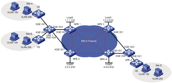
Analysis
To meet the network requirements, you must perform the following tasks:
· For NPEs to identify user traffic, enable QinQ and add an outer tag (the provider VLAN tag) to upstream packets on the downlink port of each UPE.
· Use STP to prevent loops and implement link redundancy.
· To forward packets from a UPE through the bound PW, configure service instances to match the outer provider tag of packets on the downlink port of each NPE.
· To negotiate inner labels, configure any two NPEs as LDP peers.
· To retain the VLAN information for each site, you can configure both the AC access mode and the PW type as VLAN. By default, the AC access mode and the PW type are VLAN.
Procedures
Configuring basic settings
# Configure an IGP on the MPLS backbone to ensure that the interfaces of NPEs are reachable to each other. (Details not shown.)
# Configure basic MPLS and MPLS LDP on the MPLS backbone to establish LDP LSPs. (Details not shown.)
# Configure the ports of CEs connecting the UPEs as trunk ports that permit tagged packets from VLAN 100 and VLAN 200. (Details not shown.)
Configuring UPE 1
# Enable the spanning tree feature globally, and configure UPE 1 to operate in PVST mode.
<UPE1> system-view
[UPE1] stp global enable
[UPE1] stp mode pvst
# Enable QinQ on Ten-GigabitEthernet 1/0/1 and add an outer provider VLAN tag of 1000 to packets.
[UPE1] vlan 1000
[UPE1-vlan1000] quit
[UPE1] interface ten-gigabitethernet 1/0/1
[UPE1-Ten-GigabitEthernet1/0/1] port access vlan 1000
[UPE1-Ten-GigabitEthernet1/0/1] qinq enable
[UPE1-Ten-GigabitEthernet1/0/1] quit
# Enable QinQ on Ten-GigabitEthernet 1/0/2 and add an outer provider VLAN tag of 1000 to packets.
[UPE1] interface ten-gigabitethernet 1/0/2
[UPE1-Ten-GigabitEthernet1/0/2] port access vlan 1000
[UPE1-Ten-GigabitEthernet1/0/2] qinq enable
[UPE1-Ten-GigabitEthernet1/0/2] quit
# Configure Ten-GigabitEthernet 1/0/3 as a trunk port that allows forwarding packets tagged with VLAN 1000 to NPE 1.
[UPE1] interface ten-gigabitethernet 1/0/3
[UPE1-Ten-GigabitEthernet1/0/3] port link-type trunk
[UPE1-Ten-GigabitEthernet1/0/3] port trunk permit vlan 1000
[UPE1-Ten-GigabitEthernet1/0/3] quit
# Configure Ten-GigabitEthernet 1/0/4 as a trunk port that allows forwarding packets tagged with VLAN 1000 to NPE 2.
[UPE1] interface ten-gigabitethernet 1/0/4
[UPE1-Ten-GigabitEthernet1/0/4] port link-type trunk
[UPE1-Ten-GigabitEthernet1/0/4] port trunk permit vlan 1000
[UPE1-Ten-GigabitEthernet1/0/4] quit
Configuring NPE 1
# Enable MPLS L2VPN.
[NPE1] l2vpn enable
# Create VSI user_a and configure the VSI to use LDP as the PW signaling protocol.
[NPE1] vsi user_a
[NPE1-vsi-user_a] pwsignaling ldp
# Establish a PW to NPE 2.
[NPE1-vsi-user_a-ldp] peer 2.2.2.2 pw-id 500
[NPE1-vsi-user_a-ldp-2.2.2.2-500] quit
# Establish a PW to NPE 3.
[NPE1-vsi-user_a-ldp] peer 3.3.3.3 pw-id 500
[NPE1-vsi-user_a-ldp-3.3.3.3-500] quit
# Establish a PW to NPE 4.
[NPE1-vsi-user_a-ldp] peer 4.4.4.4 pw-id 500
[NPE1-vsi-user_a-ldp-4.4.4.4-500] quit
[NPE1-vsi-user_a-ldp] quit
[NPE1-vsi-user_a] quit
# Create service instance 1000 on Ten-GigabitEthernet 1/0/1 (the interface connected to UPE 1) to match packets from VLAN 1000. Bind the service instance with VSI user_a.
[NPE1] interface ten-gigabitethernet 1/0/1
[NPE1-Ten-GigabitEthernet1/0/1] service-instance 1000
[NPE1-Ten-GigabitEthernet1/0/1-srv1000] encapsulation s-vid 1000
[NPE1-Ten-GigabitEthernet1/0/1-srv1000] xconnect vsi user_a access-mode vlan
[NPE1-Ten-GigabitEthernet1/0/1-srv1000] quit
Configuring NPE 2
# Configure NPE 2 in the same way that NPE 1 is configured. (Details not shown.)
Configuring UPE 2
# Enable the spanning tree feature globally, and configure UPE 2 to operate in PVST mode.
<UPE2> system-view
[UPE2] stp global enable
[UPE2] stp mode pvst
# Enable QinQ on Ten-GigabitEthernet 1/0/1 and add an outer provider VLAN tag of 1000 to packets. The VLAN tag must be the same as that configured on UPE 1.
[UPE2] vlan 1000
[UPE2-vlan1000] quit
[UPE2] interface ten-gigabitethernet 1/0/1
[UPE2-Ten-GigabitEthernet1/0/1] port access vlan 1000
[UPE2-Ten-GigabitEthernet1/0/1] qinq enable
[UPE2-Ten-GigabitEthernet1/0/1] quit
# Configure Ten-GigabitEthernet 1/0/3 as a trunk port that allows forwarding packets tagged with VLAN 1000 to NPE 3.
[UPE2] interface ten-gigabitethernet 1/0/3
[UPE2-Ten-GigabitEthernet1/0/3] port link-type trunk
[UPE2-Ten-GigabitEthernet1/0/3] port trunk permit vlan 1000
[UPE2-Ten-GigabitEthernet1/0/3] quit
# Configure Ten-GigabitEthernet 1/0/4 as a trunk port that allows forwarding packets tagged with VLAN 1000 to NPE 4.
[UPE2] interface ten-gigabitethernet 1/0/4
[UPE2-Ten-GigabitEthernet1/0/4] port link-type trunk
[UPE2-Ten-GigabitEthernet1/0/4] port trunk permit vlan 1000
[UPE2-Ten-GigabitEthernet1/0/4] quit
Configuring NPE 3
# Enable MPLS L2VPN.
[NPE3] l2vpn enable
# Create VSI user_a and configure the VSI to use LDP as the PW signaling protocol.
[NPE3] vsi user_a
[NPE3-vsi-user_a] pwsignaling ldp
# Establish a PW to NPE 1.
[NPE3-vsi-user_a-ldp] peer 1.1.1.1 pw-id 500
[NPE3-vsi-user_a-ldp-1.1.1.1-500] quit
# Establish a PW to NPE 2.
[NPE3-vsi-user_a-ldp] peer 2.2.2.2 pw-id 500
[NPE3-vsi-user_a-ldp-2.2.2.2-500] quit
# Establish a PW to NPE 4.
[NPE3-vsi-user_a-ldp] peer 4.4.4.4 pw-id 500
[NPE3-vsi-user_a-ldp-4.4.4.4-500] quit
[NPE3-vsi-user_a-ldp] quit
[NPE3-vsi-user_a] quit
# Create service instance 1000 on Ten-GigabitEthernet 1/0/1 (the interface connected to UPE 2) to match packets from VLAN 1000. Bind the service instance with VSI user_a.
[NPE3] interface ten-gigabitethernet 1/0/1
[NPE3-Ten-GigabitEthernet1/0/1] service-instance 1000
[NPE3-Ten-GigabitEthernet1/0/1-srv1000] encapsulation s-vid 1000
[NPE3-Ten-GigabitEthernet1/0/1-srv1000] xconnect vsi user_a access-mode vlan
[NPE3-Ten-GigabitEthernet1/0/1-srv1000] quit
Configuring NPE 4
# Configure NPE 4 in the same way that NPE 3 is configured. (Details not shown.)
Verifying the configuration
# Verify that LDP PWs in up state have been established on each NPE. This example uses NPE 1.
[NPE1] display l2vpn pw
Flags: M - main, B - backup, H - hub link, S - spoke link, N - no split horizon
Total number of PWs: 3, 3 up, 0 blocked, 0 down, 0 defect
VSI Name: user_a
Peer PW ID/Rmt Site In/Out Label Proto Flag Link ID State
2.2.2.2 500 131199/131199 LDP M 256 Up
3.3.3.3 500 131198/131198 LDP M 257 Up
4.4.4.4 500 131197/131197 LDP M 258 Up
# Verify that hosts in the same VLAN but different sites can ping each other. (Details not shown.)
Configuration files
The following lists only the H-VPLS-related configuration files. CE configuration and PE routing configuration are not shown.
· UPE 1:
#
vlan 1000
#
interface Ten-GigabitEthernet1/0/1
port link-mode bridge
port access vlan 1000
qinq enable
#
interface Ten-GigabitEthernet1/0/2
port link-mode bridge
port access vlan 1000
qinq enable
#
interface Ten-GigabitEthernet1/0/3
port link-mode bridge
port link-type trunk
port trunk permit vlan 1 1000
#
interface Ten-GigabitEthernet1/0/4
port link-mode bridge
port link-type trunk
port trunk permit vlan 1 1000
#
· NPE 1:
#
mpls lsr-id 1.1.1.1
#
mpls ldp
#
l2vpn enable
#
vsi user_a
pwsignaling ldp
peer 2.2.2.2 pw-id 500
peer 3.3.3.3 pw-id 500
peer 4.4.4.4 pw-id 500
#
interface Ten-GigabitEthernet1/0/1
port link-mode bridge
service-instance 1000
encapsulation s-vid 1000
xconnect vsi user_a
#
· NPE 2:
#
mpls lsr-id 2.2.2.2
#
mpls ldp
#
l2vpn enable
#
vsi user_a
pwsignaling ldp
peer 1.1.1.1 pw-id 500
peer 3.3.3.3 pw-id 500
peer 4.4.4.4 pw-id 500
#
interface Ten-GigabitEthernet1/0/1
port link-mode bridge
service-instance 1000
encapsulation s-vid 1000
xconnect vsi user_a
#
· UPE 2:
#
vlan 1000
#
interface Ten-GigabitEthernet1/0/1
port link-mode bridge
port access vlan 1000
qinq enable
#
interface Ten-GigabitEthernet1/0/3
port link-mode bridge
port link-type trunk
port trunk permit vlan 1 1000
#
interface Ten-GigabitEthernet1/0/4
port link-mode bridge
port link-type trunk
port trunk permit vlan 1 1000
#
· NPE 3:
#
mpls lsr-id 3.3.3.3
#
mpls ldp
#
l2vpn enable
#
vsi user_a
pwsignaling ldp
peer 1.1.1.1 pw-id 500
peer 2.2.2.2 pw-id 500
peer 4.4.4.4 pw-id 500
#
interface Ten-GigabitEthernet1/0/1
port link-mode bridge
service-instance 1000
encapsulation s-vid 1000
xconnect vsi user_a
#
· NPE 4:
#
mpls lsr-id 4.4.4.4
#
mpls ldp
#
l2vpn enable
#
vsi user_a
pwsignaling ldp
peer 1.1.1.1 pw-id 500
peer 2.2.2.2 pw-id 500
peer 3.3.3.3 pw-id 500
#
interface Ten-GigabitEthernet1/0/1
port link-mode bridge
service-instance 1000
encapsulation s-vid 1000
xconnect vsi user_a
#
Related documentation
· H3C S7500E Switch Series MPLS Command Reference-R757X
· H3C S7500E Switch Series MPLS Configuration Guide-R757X
