- Table of Contents
-
- 07-MPLS Configuration Examples
- 01-H3C_HoVPN_Configuration_Examples
- 02-H3C_MCE_Configuration_Examples
- 03-H3C_MPLS_L2VPN_Configuration_Examples
- 04-H3C_MPLS_L3VPN_Configuration_Examples
- 05-H3C_MPLS_TE_Configuration_Examples
- 06-H3C_MPLS_TE_Forwarding_Adjacency_Configuration_Examples
- 07-H3C_Basic_MPLS_Configuration_Examples
- 08-H3C_VPLS_Configuration_Examples
- 09-H3C_GRE Tunnel Access to MPLS L3VPN Configuration Examples
- Related Documents
-
| Title | Size | Download |
|---|---|---|
| 03-H3C_MPLS_L2VPN_Configuration_Examples | 304.65 KB |
H3C MPLS L2VPN Configuration Examples
Software version: Release 7577P04
Document version: 6W100-20190330
Copyright © 2019 New H3C Technologies Co., Ltd. All rights reserved.
No part of this manual may be reproduced or transmitted in any form or by any means without prior written consent of New H3C Technologies Co., Ltd.
Except for the trademarks of New H3C Technologies Co., Ltd., any trademarks that may be mentioned in this document are the property of their respective owners.
The information in this document is subject to change without notice.
Introduction
This document provides MPLS L2VPN configuration examples.
MPLS L2VPN is an MPLS-based Layer 2 VPN technology. It can transparently transmit Layer 2 data for different data link layer protocols over an MPLS network.
MPLS L2VPN can be implemented through the following PWs:
· CCC PWs.
· Static PWs.
· LDP PWs.
· BGP PWs.
Prerequisites
The configuration examples in this document were created and verified in a lab environment, and all the devices were started with the factory default configuration. When you are working on a live network, make sure you understand the potential impact of every command on your network.
This document assumes that you have basic knowledge of MPLS L2VPN.
Example: Configuring remote CCC connections
Network configuration
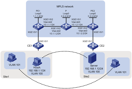
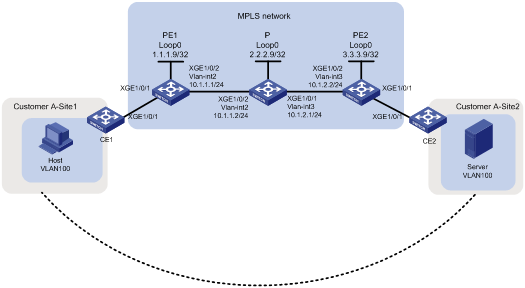
As shown in Figure 1, configure remote CCC connections between PE 1 and PE 2 to allow communication between the two sites as if they were in the same LAN. The same VLAN in different sites can communicate with each other.
Analysis
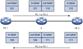
To establish a remote CCC connection, specify the incoming and outgoing labels on the PEs, and create a static LSP for each direction of the connection on the P device. The outgoing label specified on a device must be the same as the incoming label specified on the next hop device as shown in Figure 2.
Figure 2 Incoming and outgoing label assignment
Procedures
1. Configure VLAN interfaces and enable basic MPLS on the interfaces:
# On PE 1, configure an LSR ID.
<PE1> system-view
[PE1] interface loopback 0
[PE1-LoopBack0] ip address 1.1.1.9 32
[PE1-LoopBack0] quit
[PE1] mpls lsr-id 1.1.1.9
# On PE 1, enable MPLS L2VPN globally.
[PE1] l2vpn enable
# On PE 1, create VLAN 2 and assign Ten-GigabitEthernet 1/0/2 to the VLAN.
[PE1] vlan 2
[PE1-vlan2] port Ten-GigabitEthernet 1/0/2
[PE1-vlan2] quit
# On PE 1, configure VLAN-interface 2 and enable MPLS on it.
[PE1] interface vlan-interface 2
[PE1-Vlan-interface2] ip address 10.1.1.1 24
[PE1-Vlan-interface2] mpls enable
[PE1-Vlan-interface2] quit
# On P, configure an LSR ID.
<P> system-view
[P] interface loopback 0
[P-LoopBack0] ip address 2.2.2.9 32
[P-LoopBack0] quit
[P] mpls lsr-id 2.2.2.9
# On P, create VLAN 3 and assign Ten-GigabitEthernet 1/0/1 to the VLAN.
[P] vlan3
[P-vlan3] port Ten-GigabitEthernet1/0/1
[P-vlan3] quit
# On P, configure VLAN-interface 3 and enable MPLS on it.
[P] interface vlan-interface 3
[P-Vlan-interface3] ip address 10.1.2.1 24
[P-Vlan-interface3] mpls enable
[P-Vlan-interface3] quit
# On P, create VLAN 2 and assign Ten-GigabitEthernet 1/0/2 to the VLAN.
[P] vlan2
[P-vlan2] port Ten-GigabitEthernet1/0/2
[P-vlan2] quit
# On P, configure VLAN-interface 2 and enable MPLS on it.
[P] interface vlan-interface 2
[P-Vlan-interface2] ip address 10.1.1.2 24
[P-Vlan-interface2] mpls enable
[P-Vlan-interface2] quit
# On PE 2, configure an LSR ID.
<PE2> system-view
[PE2] interface loopback 0
[PE2-LoopBack0] ip address 3.3.3.9 32
[PE2-LoopBack0] quit
[PE2] mpls lsr-id 3.3.3.9
# On PE 2, enable MPLS L2VPN globally.
[PE2] l2vpn enable
# On PE 2, create VLAN 3 and assign Ten-GigabitEthernet 1/0/2 to the VLAN.
[PE2] vlan 3
[PE2-vlan3] port Ten-GigabitEthernet 1/0/2
[PE2-vlan3] quit
# On PE 2, configure VLAN-interface 3 and enable MPLS on it.
[PE2] interface vlan-interface 3
[PE2-Vlan-interface3] ip address 10.1.2.2 24
[PE2-Vlan-interface3] mpls enable
[PE2-Vlan-interface3] quit
2. Configure remote CCC connections on PEs and configure static LSPs on P:
# On PE 1, create service instance 100 on Ten-GigabitEthernet 1/0/1 to match packets from VLAN 100.
[PE1] interface ten-gigabitethernet1/0/1
[PE1-Ten-GigabitEthernet1/0/1] service-instance 100
[PE1-Ten-GigabitEthernet1/0/1-srv100] encapsulation s-vid 100
[PE1-Ten-GigabitEthernet1/0/1-srv100] quit
# On PE 1, create service instance 101 on Ten-GigabitEthernet 1/0/1 to match packets from VLAN 101.
[PE1-Ten-GigabitEthernet1/0/1] service-instance 101
[PE1-Ten-GigabitEthernet1/0/1-srv101] encapsulation s-vid 101
[PE1-Ten-GigabitEthernet1/0/1-srv101] quit
[PE1-Ten-GigabitEthernet1/0/1] quit
# On PE 1, create cross-connect group vpna, and create remote CCC connection CCC that has incoming label 100, outgoing label 101, and next hop 10.1.1.2.
[PE1] xconnect-group vpna
[PE1-xcg-vpna] connection ccc
[PE1-xcg-vpna-ccc] ccc in-label 100 out-label 101 nexthop 10.1.1.2
# On PE 1, bind service instance 100 on Ten-GigabitEthernet 1/0/1 to the CCC connection.
[PE1-xcg-vpna-ccc] ac interface ten-gigabitethernet 1/0/1 service-instance 100
[PE1-xcg-vpna-ccc] quit
[PE1-xcg-vpna] quit
# On PE 1, create cross-connect group vpnb, and create remote CCC connection CCC that has incoming label 200, outgoing label 201, and next hop 10.1.1.2.
[PE1] xconnect-group vpnb
[PE1-xcg-vpnb] connection ccc
[PE1-xcg-vpnb-ccc] ccc in-label 200 out-label 201 nexthop 10.1.1.2
# On PE 1, bind service instance 101 on Ten-GigabitEthernet 1/0/1 to the CCC connection.
[PE1-xcg-vpnb-ccc] ac interface ten-gigabitethernet 1/0/1 service-instance 101
[PE1-xcg-vpnb-ccc] quit
[PE1-xcg-vpnb] quit
# On P, create a static LSP for forwarding packets of VLAN 100 from PE 1 to PE 2.
[P] static-lsp transit pe1-pe2-100 in-label 101 nexthop 10.1.2.2 out-label 110
# On P, create a static LSP for forwarding packets of VLAN 101 from PE 1 to PE 2.
[P] static-lsp transit pe1-pe2-101 in-label 201 nexthop 10.1.2.2 out-label 210
# On P, create a static LSP for forwarding packets of VLAN 100 from PE 2 to PE 1.
[P] static-lsp transit pe2-pe1-100 in-label 111 nexthop 10.1.1.1 out-label 100
# On P, create a static LSP for forwarding packets of VLAN 101 from PE 2 to PE 1.
[P] static-lsp transit pe2-pe1-101 in-label 211 nexthop 10.1.1.1 out-label 200
# On PE 2, create service instance 100 on Ten-GigabitEthernet 1/0/1 to match packets from VLAN 100.
[PE2] interface ten-gigabitethernet1/0/1
[PE2-Ten-GigabitEthernet1/0/1] service-instance 100
[PE2-Ten-GigabitEthernet1/0/1-srv100] encapsulation s-vid 100
[PE2-Ten-GigabitEthernet1/0/1-srv100] quit
# On PE 2, create service instance 101 on Ten-GigabitEthernet 1/0/1 to match packets from VLAN 101.
[PE2-Ten-GigabitEthernet1/0/1] service-instance 101
[PE2-Ten-GigabitEthernet1/0/1-srv101] encapsulation s-vid 101
[PE2-Ten-GigabitEthernet1/0/1-srv101] quit
[PE2-Ten-GigabitEthernet1/0/1] quit
# On PE 2, create cross-connect group vpna, and create remote CCC connection CCC that has incoming label 110, outgoing label 111, and next hop 10.1.2.1.
[PE2] xconnect-group vpna
[PE2-xcg-vpna] connection ccc
[PE2-xcg-vpna-ccc] ccc in-label 110 out-label 111 nexthop 10.1.2.1
# On PE 2, bind service instance 100 on Ten-GigabitEthernet 1/0/1 to the CCC connection.
[PE2-xcg-vpna-ccc] ac interface ten-gigabitethernet 1/0/1 service-instance 100
[PE2-xcg-vpna-ccc] quit
[PE2-xcg-vpna] quit
# On PE 2, create cross-connect group vpnb, and create remote CCC connection CCC that has incoming label 210, outgoing label 211, and next hop 10.1.2.1.
[PE2] xconnect-group vpnb
[PE2-xcg-vpnb] connection ccc
[PE2-xcg-vpnb-ccc] ccc in-label 210 out-label 211 nexthop 10.1.2.1
# On PE 2, bind service instance 101 on Ten-GigabitEthernet 1/0/1 to the CCC connection.
[PE2-xcg-vpnb-ccc] ac interface ten-gigabitethernet 1/0/1 service-instance 101
[PE2-xcg-vpnb-ccc] quit
[PE2-xcg-vpnb] quit
3. Allow CE access to PEs:
# On CE 1, configure Ten-GigabitEthernet 1/0/1 as a trunk port and assign the port to VLAN 100 and VLAN 101.
<CE1> system-view
[CE1] vlan 100 to 101
[CE1] interface Ten-GigabitEthernet 1/0/1
[CE1-Ten-GigabitEthernet1/0/1] port link-type trunk
[CE1-Ten-GigabitEthernet1/0/1] port trunk permit vlan 100 101
# On CE 2, configure Ten-GigabitEthernet 1/0/1 as a trunk port and assign the port to VLAN 100 and VLAN 101.
<CE2> system-view
[CE2] vlan 100 to 101
[CE2] interface Ten-GigabitEthernet 1/0/1
[CE2-Ten-GigabitEthernet1/0/1] port link-type trunk
[CE2-Ten-GigabitEthernet1/0/1] port trunk permit vlan 100 101
Verifying the configuration
# Display L2VPN PW information on PE 1. The output shows that two remote CCC connections (identified by PW ID/Rmt Site "-" and Proto Static) have been established.
[PE1] display l2vpn pw
Flags: M - main, B - backup, H - hub link, S - spoke link, N - no split horizon
Total number of PWs: 2, 2 up, 0 blocked, 0 down, 0 defect
Xconnect-group Name: vpna
Peer PW ID/Rmt Site In/Out Label Proto Flag Link ID State
10.1.1.2 - 100/101 Static M 1 Up
Xconnect-group Name: vpnb
Peer PW ID/Rmt Site In/Out Label Proto Flag Link ID State
10.1.1.2 - 200/201 Static M 1 Up
# Display L2VPN PW information on PE 2. The output shows that two remote CCC connections have been established.
[PE2] display l2vpn pw
Flags: M - main, B - backup, H - hub link, S - spoke link, N - no split horizon
Total number of PWs: 2, 2 up, 0 blocked, 0 down, 0 defect
Xconnect-group Name: vpna
Peer PW ID/Rmt Site In/Out Label Proto Flag Link ID State
10.1.2.1 - 110/111 Static M 1 Up
Xconnect-group Name: vpnb
Peer PW ID/Rmt Site In/Out Label Proto Flag Link ID State
10.1.2.1 - 210/211 Static M 1 Up
# Verify that Host A and Server can ping each other and hosts of VLAN 101 in different sites can ping each other. (Details not shown.)
Configuration files
· CE 1:
#
vlan 100 to 101
#
interface Ten-GigabitEthernet1/0/1
port link-mode bridge
port link-type trunk
port trunk permit vlan 100 to 101
#
· PE 1:
#
mpls lsr-id 1.1.1.9
#
vlan 2
#
l2vpn enable
#
interface LoopBack0
ip address 1.1.1.9 255.255.255.255
#
interface Vlan-interface2
ip address 10.1.1.1 255.255.255.0
mpls enable
#
interface Ten-GigabitEthernet1/0/1
port link-mode bridge
service-instance 100
encapsulation s-vid 100
service-instance 101
encapsulation s-vid 101
#
interface Ten-GigabitEthernet1/0/2
port link-mode bridge
port access vlan 2
#
xconnect-group vpna
connection ccc
ac interface Ten-GigabitEthernet1/0/1 service-instance 100
ccc in-label 100 out-label 101 nexthop 10.1.1.2
#
xconnect-group vpnb
connection ccc
ac interface Ten-GigabitEthernet1/0/1 service-instance 101
ccc in-label 200 out-label 201 nexthop 10.1.1.2
#
· P:
#
mpls lsr-id 2.2.2.9
#
vlan 2
#
vlan 3
#
interface LoopBack0
ip address 2.2.2.9 255.255.255.255
#
interface Vlan-interface2
ip address 10.1.1.2 255.255.255.0
mpls enable
#
interface Vlan-interface3
ip address 10.1.2.1 255.255.255.0
mpls enable
#
interface Ten-GigabitEthernet1/0/1
port link-mode bridge
port access vlan 3
#
interface Ten-GigabitEthernet1/0/2
port link-mode bridge
port access vlan 2
#
static-lsp transit pe1-pe2-100 in-label 101 nexthop 10.1.2.2 out-label 110
static-lsp transit pe1-pe2-101 in-label 201 nexthop 10.1.2.2 out-label 210
static-lsp transit pe2-pe1-100 in-label 111 nexthop 10.1.1.1 out-label 100
static-lsp transit pe2-pe1-101 in-label 211 nexthop 10.1.1.1 out-label 200
#
· PE 2:
#
mpls lsr-id 3.3.3.9
#
vlan 3
#
l2vpn enable
#
interface LoopBack0
ip address 3.3.3.9 255.255.255.255
#
interface Vlan-interface3
ip address 10.1.2.2 255.255.255.0
mpls enable
#
interface Ten-GigabitEthernet1/0/1
port link-mode bridge
service-instance 100
encapsulation s-vid 100
service-instance 101
encapsulation s-vid 101
#
interface Ten-GigabitEthernet1/0/2
port link-mode bridge
port access vlan 3
#
xconnect-group vpna
connection ccc
ac interface Ten-GigabitEthernet1/0/1 service-instance 100
ccc in-label 110 out-label 111 nexthop 10.1.2.1
#
xconnect-group vpnb
connection ccc
ac interface Ten-GigabitEthernet1/0/1 service-instance 101
ccc in-label 210 out-label 211 nexthop 10.1.2.1
#
· CE 2:
#
vlan 100 to 101
#
interface Ten-GigabitEthernet1/0/1
port link-mode bridge
port link-type trunk
port trunk permit vlan 100 to 101
#
Example: Configuring static PWs
Network configuration
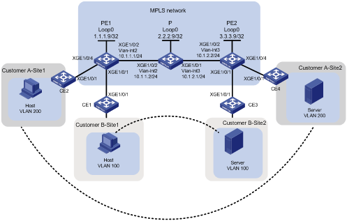
As shown in Figure 3, the MPLS network provides L2VPN services for two customers. Each customer has two fixed sites. Configure static PWs between PE 1 and PE 2 to allow communication between the sites of the same customer.
Analysis
To use static PWs to implement MPLS L2VPN, configure two levels of labels:
· Inner labels—PW labels specified manually.
· Outer labels—Public tunnel labels dynamically generated by LDP in this example.
To ensure that a static PW can be successfully established for the sites of a customer, specify the incoming label on the local PE the same as the outgoing label on the remote PE.
Procedures
1. Configure OSPF on the MPLS backbone to ensure IP connectivity within the backbone:
# On PE 1, configure an IP address for Loopback 0.
<PE1> system-view
[PE1] interface loopback 0
[PE1-LoopBack0] ip address 1.1.1.9 32
[PE1-LoopBack0] quit
# On PE 1, create VLAN 2 and assign Ten-GigabitEthernet 1/0/2 to the VLAN.
[PE1] vlan 2
[PE1-vlan2] port Ten-GigabitEthernet 1/0/2
[PE1-vlan2] quit
# On PE 1, configure VLAN-interface 2.
[PE1] interface vlan-interface 2
[PE1-Vlan-interface2] ip address 10.1.1.1 24
[PE1-Vlan-interface2] quit
# On PE 1, configure OSPF.
[PE1] ospf
[PE1-ospf-1] area 0
[PE1-ospf-1-area-0.0.0.0] network 10.1.1.0 0.0.0.255
[PE1-ospf-1-area-0.0.0.0] network 1.1.1.9 0.0.0.0
[PE1-ospf-1-area-0.0.0.0] quit
[PE1-ospf-1] quit
# On P, configure an IP address for Loopback 0.
<P> system-view
[P] interface loopback 0
[P-LoopBack0] ip address 2.2.2.9 32
[P-LoopBack0] quit
# On P, create VLAN 2 and assign Ten-GigabitEthernet 1/0/2 to the VLAN.
[P] vlan 2
[P-vlan2] port Ten-GigabitEthernet1/0/2
[P-vlan2] quit
# On P, configure VLAN-interface 2.
[P] interface vlan-interface 2
[P-Vlan-interface2] ip address 10.1.1.2 24
[P-Vlan-interface2] quit
# On P, create VLAN 3 and assign Ten-GigabitEthernet 1/0/1 to the VLAN.
[P] vlan 3
[P-vlan3] port Ten-GigabitEthernet1/0/1
[P-vlan3] quit
# On P, configure VLAN-interface 3.
[P] interface vlan-interface 3
[P-Vlan-interface3] ip address 10.1.2.1 24
[P-Vlan-interface3] quit
# On P, configure OSPF.
[P] ospf
[P-ospf-1] area 0
[P-ospf-1-area-0.0.0.0] network 10.1.1.0 0.0.0.255
[P-ospf-1-area-0.0.0.0] network 10.1.2.0 0.0.0.255
[P-ospf-1-area-0.0.0.0] network 2.2.2.9 0.0.0.0
[P-ospf-1-area-0.0.0.0] quit
[P-ospf-1] quit
# On PE 2, configure an IP address for Loopback 0.
<PE2> system-view
[PE2] interface loopback 0
[PE2-LoopBack0] ip address 3.3.3.9 32
[PE2-LoopBack0] quit
# On PE 2, create VLAN 3 and assign Ten-GigabitEthernet 1/0/2 to the VLAN.
[PE2] vlan 3
[PE2-vlan3] port Ten-GigabitEthernet 1/0/2
[PE2-vlan3] quit
# On PE 2, configure VLAN-interface 3.
[PE2] interface vlan-interface 3
[PE2-Vlan-interface3] ip address 10.1.2.2 24
[PE2-Vlan-interface3] quit
# On PE 2, configure OSPF.
[PE2] ospf
[PE2-ospf-1] area 0
[PE2-ospf-1-area-0.0.0.0] network 10.1.2.0 0.0.0.255
[PE2-ospf-1-area-0.0.0.0] network 3.3.3.9 0.0.0.0
[PE2-ospf-1-area-0.0.0.0] quit
[PE2-ospf-1] quit
2. Configure basic MPLS and MPLS LDP on the MPLS backbone to establish LDP LSPs:
# On PE 1, configure an LSR ID.
[PE1] mpls lsr-id 1.1.1.9
# On PE 1, enable LDP globally.
[PE1] mpls ldp
[PE1-ldp] quit
# On PE 1, enable MPLS and LDP on VLAN-interface 2.
[PE1] interface vlan-interface 2
[PE1-Vlan-interface2] mpls enable
[PE1-Vlan-interface2] mpls ldp enable
[PE1-Vlan-interface2] quit
# On P, configure an LSR ID.
[P] mpls lsr-id 2.2.2.9
# On P, enable LDP globally.
[P] mpls ldp
[P-ldp] quit
# On P, enable MPLS and LDP on VLAN-interface 2.
[P] interface vlan-interface 2
[P-Vlan-interface2] mpls enable
[P-Vlan-interface2] mpls ldp enable
[P-Vlan-interface2] quit
# On P, enable MPLS and LDP on VLAN-interface 3.
[P] interface vlan-interface 3
[P-Vlan-interface3] mpls enable
[P-Vlan-interface3] mpls ldp enable
[P-Vlan-interface3] quit
# On PE 2, configure an LSR ID.
[PE2] mpls lsr-id 3.3.3.9
# On PE 2, enable LDP globally.
[PE2] mpls ldp
[PE2-ldp] quit
# On PE 2, enable MPLS and LDP on VLAN-interface 3.
[PE2] interface vlan-interface 3
[PE2-Vlan-interface3] mpls enable
[PE2-Vlan-interface3] mpls ldp enable
[PE2-Vlan-interface3] quit
3. Enable MPLS L2VPN and assign inner labels to customers:
# On PE 1, enable MPLS L2VPN globally.
[PE1] l2vpn enable
# On PE 1, create service instance 100 on Ten-GigabitEthernet 1/0/1 to match packets from VLAN 100.
[PE1] interface ten-gigabitethernet1/0/1
[PE1-Ten-GigabitEthernet1/0/1] service-instance 100
[PE1-Ten-GigabitEthernet1/0/1-srv100] encapsulation s-vid 100
[PE1-Ten-GigabitEthernet1/0/1-srv100] quit
[PE1-Ten-GigabitEthernet1/0/1] quit
# On PE 1, create cross-connect group vpna, create cross-connect svc in the group, and bind service instance 100 on Ten-GigabitEthernet 1/0/1 to the cross-connect.
[PE1] xconnect-group vpna
[PE1-xcg-vpna] connection svc
[PE1-xcg-vpna-svc] ac interface Ten-GigabitEthernet 1/0/1 service-instance 100
# On PE 1, create a static PW for the cross-connect to bind the AC to the PW.
[PE1-xcg-vpna-svc] peer 3.3.3.9 pw-id 100 in-label 101 out-label 100
[PE1-xcg-vpna-svc-3.3.3.9-100] quit
[PE1-xcg-vpna-svc] quit
[PE1-xcg-vpna] quit
# On PE 1, create service instance 200 on Ten-GigabitEthernet 1/0/4 to match packets from VLAN 200.
[PE1] interface ten-gigabitethernet1/0/4
[PE1-Ten-GigabitEthernet1/0/4] service-instance 200
[PE1-Ten-GigabitEthernet1/0/4-srv200] encapsulation s-vid 200
[PE1-Ten-GigabitEthernet1/0/4-srv200] quit
[PE1-Ten-GigabitEthernet1/0/4] quit
# On PE 1, create cross-connect group vpnb, create cross-connect svc in the group, and bind service instance 200 on Ten-GigabitEthernet 1/0/4 to the cross-connect.
[PE1] xconnect-group vpnb
[PE1-xcg-vpnb] connection svc
[PE1-xcg-vpnb-svc] ac interface Ten-GigabitEthernet 1/0/4 service-instance 200
# On PE 1, create a static PW for the cross-connect to bind the AC to the PW.
[PE1-xcg-vpnb-svc] peer 3.3.3.9 pw-id 200 in-label 201 out-label 200
[PE1-xcg-vpnb-svc-3.3.3.9-200] quit
[PE1-xcg-vpnb-svc] quit
[PE1-xcg-vpnb] quit
# On PE 2, enable MPLS L2VPN globally.
[PE2] l2vpn enable
# On PE 2, create service instance 100 on Ten-GigabitEthernet 1/0/1 to match packets from VLAN 100.
[PE2] interface ten-gigabitethernet1/0/1
[PE2-Ten-GigabitEthernet1/0/1] service-instance 100
[PE2-Ten-GigabitEthernet1/0/1-srv100] encapsulation s-vid 100
[PE2-Ten-GigabitEthernet1/0/1-srv100] quit
[PE2-Ten-GigabitEthernet1/0/1] quit
# On PE 2, create service instance 200 on Ten-GigabitEthernet 1/0/4 to match packets from VLAN 200.
[PE2] interface ten-gigabitethernet1/0/4
[PE2-Ten-GigabitEthernet1/0/4] service-instance 200
[PE2-Ten-GigabitEthernet1/0/4-srv200] encapsulation s-vid 200
[PE2-Ten-GigabitEthernet1/0/4-srv200] quit
[PE2-Ten-GigabitEthernet1/0/4] quit
# On PE 2, create cross-connect group vpna, create cross-connect svc in the group, and bind service instance 100 on Ten-GigabitEthernet 1/0/1 to the cross-connect.
[PE2] xconnect-group vpna
[PE2-xcg-vpna] connection svc
[PE2-xcg-vpna-svc] ac interface Ten-GigabitEthernet 1/0/1 service-instance 100
# On PE 2, create a static PW for the cross-connect to bind the AC to the PW.
[PE2-xcg-vpna-svc] peer 1.1.1.9 pw-id 100 in-label 100 out-label 101
[PE2-xcg-vpna-svc-1.1.1.9-100] quit
[PE2-xcg-vpna-svc] quit
[PE2-xcg-vpna] quit
# On PE 2, create cross-connect group vpnb, create cross-connect svc in the group, and bind service instance 200 on Ten-GigabitEthernet 1/0/4 to the cross-connect.
[PE2] xconnect-group vpnb
[PE2-xcg-vpnb] connection svc
[PE2-xcg-vpnb-svc] ac interface Ten-GigabitEthernet 1/0/4 service-instance 200
# On PE 2, create a static PW for the cross-connect to bind the AC to the PW.
[PE2-xcg-vpnb-svc] peer 1.1.1.9 pw-id 200 in-label 200 out-label 201
[PE2-xcg-vpnb-svc-1.1.1.9-200] quit
[PE2-xcg-vpnb-svc] quit
[PE2-xcg-vpnb] quit
4. Allow CE access to PEs:
# On CE 1, configure the interface connected to the PE to permit tagged packets from the customer VLAN.
<CE1> system-view
[CE1] vlan 100
[CE1-vlan100] quit
[CE1] interface Ten-GigabitEthernet 1/0/1
[CE1-Ten-GigabitEthernet1/0/1] port link-type trunk
[CE1-Ten-GigabitEthernet1/0/1] port trunk permit vlan 100
# Configure other CEs in the same way that CE 1 is configured. (Details not shown.)
Verifying the configuration
# Display L2VPN PW information on PE 1. The output shows that two static PWs have been established.
[PE1] display l2vpn pw
Flags: M - main, B - backup, H - hub link, S - spoke link, N - no split horizon
Total number of PWs: 2, 2 up, 0 blocked, 0 down, 0 defect
Xconnect-group Name: vpna
Peer PW ID In/Out Label Proto Flag Link ID State
3.3.3.9 100 101/100 Static M 1 Up
Xconnect-group Name: vpnb
Peer PW ID In/Out Label Proto Flag Link ID State
3.3.3.9 200 201/200 Static M 1 Up
# Display L2VPN PW information on PE 2. The output shows that two static PWs have been established.
[PE2] display l2vpn pw
Flags: M - main, B - backup, H - hub link, S - spoke link, N - no split horizon
Total number of PWs: 2, 2 up, 0 blocked, 0 down, 0 defect
Xconnect-group Name: vpna
Peer PW ID In/Out Label Proto Flag Link ID State
1.1.1.9 100 100/101 Static M 1 Up
Xconnect-group Name: vpnb
Peer PW ID In/Out Label Proto Flag Link ID State
1.1.1.9 200 200/201 Static M 1 Up
# Verify that the host and the server of the same customer in different sites can ping each other. (Details not shown.)
Configuration files
· CE 1:
#
vlan 100
#
interface Ten-GigabitEthernet1/0/1
port link-mode bridge
port link-type trunk
port trunk permit vlan 100
#
· CE 2:
#
vlan 200
#
interface Ten-GigabitEthernet1/0/1
port link-mode bridge
port link-type trunk
port trunk permit vlan 200
#
· CE 3:
#
vlan 100
#
interface Ten-GigabitEthernet1/0/1
port link-mode bridge
port link-type trunk
port trunk permit vlan 100
#
· CE 4:
#
vlan 200
#
interface Ten-GigabitEthernet1/0/1
port link-mode bridge
port link-type trunk
port trunk permit vlan 200
#
· PE 1:
#
ospf 1
area 0.0.0.0
network 1.1.1.9 0.0.0.0
network 10.1.1.0 0.0.0.255
#
mpls lsr-id 1.1.1.9
#
vlan 2
#
vlan 100
#
vlan 200
#
mpls ldp
#
l2vpn enable
#
interface LoopBack0
ip address 1.1.1.9 255.255.255.255
#
interface Vlan-interface2
ip address 10.1.1.1 255.255.255.0
mpls enable
mpls ldp enable
#
interface Ten-GigabitEthernet1/0/1
port link-mode bridge
service-instance 100
encapsulation s-vid 100
#
interface Ten-GigabitEthernet1/0/2
port link-mode bridge
port access vlan 2
#
interface Ten-GigabitEthernet1/0/4
port link-mode bridge
service-instance 200
encapsulation s-vid 200
#
xconnect-group vpna
connection svc
ac interface Ten-GigabitEthernet1/0/1 service-instance 100
peer 3.3.3.9 pw-id 100 in-label 101 out-label 100
#
xconnect-group vpnb
connection svc
ac interface Ten-GigabitEthernet1/0/4 service-instance 200
peer 3.3.3.9 pw-id 200 in-label 201 out-label 200
#
· P:
#
ospf 1
area 0.0.0.0
network 2.2.2.9 0.0.0.0
network 10.1.1.0 0.0.0.255
network 10.1.2.0 0.0.0.255
#
mpls lsr-id 2.2.2.9
#
vlan 2 to 3
#
mpls ldp
#
interface LoopBack0
ip address 2.2.2.9 255.255.255.255
#
interface Vlan-interface2
ip address 10.1.1.2 255.255.255.0
mpls enable
mpls ldp enable
#
interface Vlan-interface3
ip address 10.1.2.1 255.255.255.0
mpls enable
mpls ldp enable
#
interface Ten-GigabitEthernet1/0/1
port link-mode bridge
port access vlan 3
#
interface Ten-GigabitEthernet1/0/2
port link-mode bridge
port access vlan 2
#
· PE 2:
#
ospf 1
area 0.0.0.0
network 10.1.2.0 0.0.0.255
network 3.3.3.9 0.0.0.0
#
mpls lsr-id 3.3.3.9
#
vlan 3
#
vlan 100
#
vlan 200
#
mpls ldp
#
l2vpn enable
#
interface LoopBack0
ip address 3.3.3.9 255.255.255.255
#
interface Vlan-interface3
ip address 10.1.2.2 255.255.255.0
mpls enable
mpls ldp enable
#
interface Ten-GigabitEthernet1/0/1
port link-mode bridge
service-instance 100
encapsulation s-vid 100
#
interface Ten-GigabitEthernet1/0/2
port link-mode bridge
port access vlan 3
#
interface Ten-GigabitEthernet1/0/4
port link-mode bridge
service-instance 200
encapsulation s-vid 200
#
xconnect-group vpna
connection svc
ac interface Ten-GigabitEthernet1/0/1 service-instance 100
peer 1.1.1.9 pw-id 100 in-label 100 out-label 101
#
xconnect-group vpnb
connection svc
ac interface Ten-GigabitEthernet1/0/4 service-instance 200
peer 1.1.1.9 pw-id 200 in-label 200 out-label 201
#
Example: Configuring LDP PWs
Network configuration
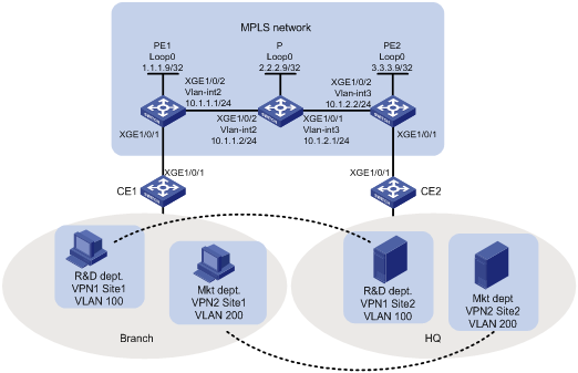
As shown in Figure 4, the MPLS network provides L2VPN services for a customer. Configure LDP PWs between PE 1 and PE 2 so the R&D and Marketing departments use different VPN connections to achieve data isolation.
Analysis
To use LDP PWs to implement MPLS L2VPN, configure two levels of labels:
· Inner labels—PW labels dynamically generated by LDP.
· Outer labels—Public tunnel labels dynamically generated by LDP in this example.
To identify packets to be transported by MPLS L2VPN, configure service instances and match criteria on the CE-facing ports of PEs.
Procedures
1. Configure OSPF on the MPLS backbone to ensure IP connectivity within the backbone:
# On PE 1, configure an IP address for Loopback 0.
<PE1> system-view
[PE1] interface loopback 0
[PE1-LoopBack0] ip address 1.1.1.9 32
[PE1-LoopBack0] quit
# On PE 1, create VLAN 2 and assign Ten-GigabitEthernet 1/0/2 to the VLAN.
[PE1] vlan 2
[PE1-vlan2] port Ten-GigabitEthernet 1/0/2
[PE1-vlan2] quit
# On PE 1, configure an IP address for VLAN-interface 2.
[PE1] interface vlan-interface 2
[PE1-Vlan-interface2] ip address 10.1.1.1 24
[PE1-Vlan-interface2] quit
# On PE 1, configure OSPF.
[PE1] ospf
[PE1-ospf-1] area 0
[PE1-ospf-1-area-0.0.0.0] network 10.1.1.0 0.0.0.255
[PE1-ospf-1-area-0.0.0.0] network 1.1.1.9 0.0.0.0
[PE1-ospf-1-area-0.0.0.0] quit
[PE1-ospf-1] quit
# On P, configure an IP address for Loopback 0.
<P> system-view
[P] interface loopback 0
[P-LoopBack0] ip address 2.2.2.9 32
[P-LoopBack0] quit
# On P, create VLAN 2 and assign Ten-GigabitEthernet 1/0/2 to the VLAN.
[P] vlan 2
[P-vlan2] port Ten-GigabitEthernet1/0/2
[P-vlan2] quit
# On P, configure an IP address for VLAN-interface 2.
[P] interface vlan-interface 2
[P-Vlan-interface2] ip address 10.1.1.2 24
[P-Vlan-interface2] quit
# On P, create VLAN 3 and assign Ten-GigabitEthernet 1/0/1 to the VLAN.
[P] vlan 3
[P-vlan3] port Ten-GigabitEthernet1/0/1
[P-vlan3] quit
# On P, configure an IP address for VLAN-interface 3.
[P] interface vlan-interface 3
[P-Vlan-interface3] ip address 10.1.2.1 24
[P-Vlan-interface3] quit
# On P, configure OSPF.
[P] ospf
[P-ospf-1] area 0
[P-ospf-1-area-0.0.0.0] network 10.1.1.0 0.0.0.255
[P-ospf-1-area-0.0.0.0] network 10.1.2.0 0.0.0.255
[P-ospf-1-area-0.0.0.0] network 2.2.2.9 0.0.0.0
[P-ospf-1-area-0.0.0.0] quit
[P-ospf-1] quit
# On PE 2, configure an IP address for Loopback 0.
<PE2> system-view
[PE2] interface loopback 0
[PE2-LoopBack0] ip address 3.3.3.9 32
[PE2-LoopBack0] quit
# On PE 2, create VLAN 3 and assign Ten-GigabitEthernet 1/0/2 to the VLAN.
[PE2] vlan 3
[PE2-vlan3] port Ten-GigabitEthernet 1/0/2
[PE2-vlan3] quit
# On PE 2, configure an IP address for VLAN-interface 3.
[PE2] interface vlan-interface 3
[PE2-Vlan-interface3] ip address 10.1.2.2 24
[PE2-Vlan-interface3] quit
# On PE 2, configure OSPF.
[PE2] ospf
[PE2-ospf-1] area 0
[PE2-ospf-1-area-0.0.0.0] network 10.1.2.0 0.0.0.255
[PE2-ospf-1-area-0.0.0.0] network 3.3.3.9 0.0.0.0
[PE2-ospf-1-area-0.0.0.0] quit
[PE2-ospf-1] quit
2. Configure basic MPLS and MPLS LDP on the MPLS backbone to establish LDP LSPs:
# On PE 1, configure an LSR ID.
[PE1] mpls lsr-id 1.1.1.9
# On PE 1, enable LDP globally.
[PE1] mpls ldp
[PE1-ldp] quit
# On PE 1, enable MPLS and LDP on VLAN-interface 2.
[PE1] interface vlan-interface 2
[PE1-Vlan-interface2] mpls enable
[PE1-Vlan-interface2] mpls ldp enable
[PE1-Vlan-interface2] quit
# On P, configure an LSR ID.
[P] mpls lsr-id 2.2.2.9
# On P, enable LDP globally.
[P] mpls ldp
[P-ldp] quit
# On P, enable MPLS and LDP on VLAN-interface 2.
[P] interface vlan-interface 2
[P-Vlan-interface2] mpls enable
[P-Vlan-interface2] mpls ldp enable
[P-Vlan-interface2] quit
# On P, enable MPLS and LDP on VLAN-interface 3.
[P] interface vlan-interface 3
[P-Vlan-interface3] mpls enable
[P-Vlan-interface3] mpls ldp enable
[P-Vlan-interface3] quit
# On PE 2, configure an LSR ID.
[PE2] mpls lsr-id 3.3.3.9
# On PE 2, enable LDP globally.
[PE2] mpls ldp
[PE2-ldp] quit
# On PE 2, enable MPLS and LDP on VLAN-interface 3.
[PE2] interface vlan-interface 3
[PE2-Vlan-interface3] mpls enable
[PE2-Vlan-interface3] mpls ldp enable
[PE2-Vlan-interface3] quit
3. Configure a service instance for each department and bind the service instances to their respective VPN connections:
# On PE 1, enable MPLS L2VPN globally.
[PE1] l2vpn enable
# On PE 1, create service instance 100 on Ten-GigabitEthernet 1/0/1 to match packets from VLAN 100.
[PE1] interface ten-gigabitethernet1/0/1
[PE1-Ten-GigabitEthernet1/0/1] service-instance 100
[PE1-Ten-GigabitEthernet1/0/1-srv100] encapsulation s-vid 100
[PE1-Ten-GigabitEthernet1/0/1-srv100] quit
# On PE 1, create service instance 200 on Ten-GigabitEthernet 1/0/1 to match packets from VLAN 200.
[PE1-Ten-GigabitEthernet1/0/1] service-instance 200
[PE1-Ten-GigabitEthernet1/0/1-srv200] encapsulation s-vid 200
[PE1-Ten-GigabitEthernet1/0/1-srv200] quit
[PE1-Ten-GigabitEthernet1/0/1] quit
# On PE 1, create cross-connect group vpna, create cross-connect ldp in the group, and bind service instance 100 on Ten-GigabitEthernet 1/0/1 to the cross-connect.
[PE1] xconnect-group vpna
[PE1-xcg-vpna] connection ldp
[PE1-xcg-vpna-ldp] ac interface Ten-GigabitEthernet 1/0/1 service-instance 100
# On PE 1, create an LDP PW for the cross-connect to bind the AC to the PW.
[PE1-xcg-vpna-ldp] peer 3.3.3.9 pw-id 100
[PE1-xcg-vpna-ldp-3.3.3.9-100] quit
[PE1-xcg-vpna-ldp] quit
[PE1-xcg-vpna] quit
# On PE 1, create cross-connect group vpnb, create cross-connect ldp in the group, and bind service instance 200 on Ten-GigabitEthernet 1/0/1 to the cross-connect.
[PE1] xconnect-group vpnb
[PE1-xcg-vpnb] connection ldp
[PE1-xcg-vpnb-ldp] ac interface Ten-GigabitEthernet 1/0/1 service-instance 200
# On PE 1, create an LDP PW for the cross-connect to bind the AC to the PW.
[PE1-xcg-vpnb-ldp] peer 3.3.3.9 pw-id 200
[PE1-xcg-vpnb-ldp-3.3.3.9-200] quit
[PE1-xcg-vpnb-ldp] quit
[PE1-xcg-vpnb] quit
# On PE 2, enable MPLS L2VPN globally.
[PE2] l2vpn enable
# On PE 2, create service instance 100 on Ten-GigabitEthernet 1/0/1 to match packets from VLAN 100.
[PE2] interface ten-gigabitethernet1/0/1
[PE2-Ten-GigabitEthernet1/0/1] service-instance 100
[PE2-Ten-GigabitEthernet1/0/1-srv100] encapsulation s-vid 100
[PE2-Ten-GigabitEthernet1/0/1-srv100] quit
# On PE 2, create service instance 200 on Ten-GigabitEthernet 1/0/1 to match packets from VLAN 200.
[PE2-Ten-GigabitEthernet1/0/1] service-instance 200
[PE2-Ten-GigabitEthernet1/0/1-srv200] encapsulation s-vid 200
[PE2-Ten-GigabitEthernet1/0/1-srv200] quit
[PE2-Ten-GigabitEthernet1/0/1] quit
# On PE 2, create cross-connect group vpna, create cross-connect ldp in the group, and bind service instance 100 on Ten-GigabitEthernet 1/0/1 to the cross-connect.
[PE2] xconnect-group vpna
[PE2-xcg-vpna] connection ldp
[PE2-xcg-vpna-ldp] ac interface Ten-GigabitEthernet 1/0/1 service-instance 100
# On PE 2, create an LDP PW for the cross-connect to bind the AC to the PW.
[PE2-xcg-vpna-ldp] peer 1.1.1.9 pw-id 100
[PE2-xcg-vpna-ldp-1.1.1.9-100] quit
[PE2-xcg-vpna-ldp] quit
[PE2-xcg-vpna] quit
# On PE 2, create cross-connect group vpnb, create cross-connect ldp in the group, and bind service instance 200 on Ten-GigabitEthernet 1/0/1 to the cross-connect.
[PE2] xconnect-group vpnb
[PE2-xcg-vpnb] connection ldp
[PE2-xcg-vpnb-ldp] ac interface Ten-GigabitEthernet 1/0/1 service-instance 200
# On PE 2, create an LDP PW for the cross-connect to bind the AC to the PW.
[PE2-xcg-vpnb-ldp] peer 1.1.1.9 pw-id 200
[PE2-xcg-vpnb-ldp-1.1.1.9-200] quit
[PE2-xcg-vpnb-ldp] quit
[PE2-xcg-vpnb] quit
4. Allow CE access to PEs:
# On CE 1, configure the interface connected to the PE to permit tagged packets from the customer VLANs.
<CE1> system-view
[CE1] vlan 100
[CE1-vlan100] quit
[CE1] vlan 200
[CE1-vlan200] quit
[CE1] interface Ten-GigabitEthernet 1/0/1
[CE1-Ten-GigabitEthernet1/0/1] port link-type trunk
[CE1-Ten-GigabitEthernet1/0/1] port trunk permit vlan 100 200
# Configure other CEs in the same way that CE 1 is configured. (Details not shown.)
Verifying the configuration
# Display L2VPN PW information on PE 1. The output shows that two LDP PWs have been established.
[PE1] display l2vpn pw
Flags: M - main, B - backup, H - hub link, S - spoke link, N - no split horizon
Total number of PWs: 2, 2 up, 0 blocked, 0 down, 0 defect
Xconnect-group Name: vpna
Peer PW ID In/Out Label Proto Flag Link ID State
3.3.3.9 100 65663/65663 LDP M 1 Up
Xconnect-group Name: vpnb
Peer PW ID In/Out Label Proto Flag Link ID State
3.3.3.9 200 65662/65662 LDP M 1 Up
# Display L2VPN PW information on PE 2. The output shows that two LDP PWs have been established.
[PE2] display l2vpn pw
Flags: M - main, B - backup, H - hub link, S - spoke link, N - no split horizon
Total number of PWs: 2, 2 up, 0 blocked, 0 down, 0 defect
Xconnect-group Name: vpna
Peer PW ID In/Out Label Proto Flag Link ID State
1.1.1.9 100 65663/65663 LDP M 1 Up
Xconnect-group Name: vpnb
Peer PW ID In/Out Label Proto Flag Link ID State
1.1.1.9 200 65662/65662 LDP M 1 Up
# Verify that the host and the server in the same VLAN can ping each other. (Details not shown.)
Configuration files
· CE 1 and CE 2:
#
vlan 100
#
vlan 200
#
interface Ten-GigabitEthernet1/0/1
port link-mode bridge
port link-type trunk
port trunk permit vlan 100 200
#
· PE 1:
#
ospf 1
area 0.0.0.0
network 1.1.1.9 0.0.0.0
network 10.1.1.0 0.0.0.255
#
mpls lsr-id 1.1.1.9
#
vlan 2
#
mpls ldp
#
l2vpn enable
#
interface LoopBack0
ip address 1.1.1.9 255.255.255.255
#
interface Vlan-interface2
ip address 10.1.1.1 255.255.255.0
mpls enable
mpls ldp enable
#
interface Ten-GigabitEthernet1/0/1
port link-mode bridge
service-instance 100
encapsulation s-vid 100
service-instance 200
encapsulation s-vid 200
#
interface Ten-GigabitEthernet1/0/2
port link-mode bridge
port access vlan 2
#
xconnect-group vpna
connection ldp
ac interface Ten-GigabitEthernet1/0/1 service-instance 100
peer 3.3.3.9 pw-id 100
#
xconnect-group vpnb
connection ldp
ac interface Ten-GigabitEthernet1/0/1 service-instance 200
peer 3.3.3.9 pw-id 200
#
· P:
#
ospf 1
area 0.0.0.0
network 10.1.1.0 0.0.0.255
network 10.1.2.0 0.0.0.255
network 2.2.2.9 0.0.0.0
#
mpls lsr-id 2.2.2.9
#
vlan 2
#
vlan 3
#
mpls ldp
#
interface LoopBack0
ip address 2.2.2.9 255.255.255.255
#
interface Vlan-interface2
ip address 10.1.1.2 255.255.255.0
mpls enable
mpls ldp enable
#
interface Vlan-interface3
ip address 10.1.2.1 255.255.255.0
mpls enable
mpls ldp enable
#
interface Ten-GigabitEthernet1/0/1
port link-mode bridge
port access vlan 3
#
interface Ten-GigabitEthernet1/0/2
port link-mode bridge
port access vlan 2
#
· PE 2:
#
ospf 1
area 0.0.0.0
network 10.1.2.0 0.0.0.255
network 3.3.3.9 0.0.0.0
#
mpls lsr-id 3.3.3.9
#
vlan 3
#
mpls ldp
#
l2vpn enable
#
interface LoopBack0
ip address 3.3.3.9 255.255.255.255
#
interface Vlan-interface3
ip address 10.1.2.2 255.255.255.0
mpls enable
mpls ldp enable
#
interface Ten-GigabitEthernet1/0/1
port link-mode bridge
service-instance 100
encapsulation s-vid 100
service-instance 200
encapsulation s-vid 200
#
interface Ten-GigabitEthernet1/0/2
port link-mode bridge
port access vlan 3
#
xconnect-group vpna
connection ldp
ac interface Ten-GigabitEthernet1/0/1 service-instance 100
peer 1.1.1.9 pw-id 100
#
xconnect-group vpnb
connection ldp
ac interface Ten-GigabitEthernet1/0/1 service-instance 200
peer 1.1.1.9 pw-id 200
#
Example: Configuring a BGP PW
Network configuration
As shown in Figure 5, a customer has two VPN sites and will add eight sites in the future. Configure a BGP PW between PE 1 and PE 2 to allow VPN communication between the two sites and reserve enough VPN resources for future extension.
Analysis
To use BGP PWs to implement MPLS L2VPN, configure two levels of labels:
· Inner labels—PW labels dynamically generated by BGP.
· Outer labels—Public tunnel labels dynamically generated by LDP in this example.
To use BGP to transmit inner labels between PEs, create a service instance and an IBGP connection, and specify the peer PE as a BGP peer on each PE.
To simplify configuration required by future expansion of the customer network, set the maximum number of CEs in the VPN to 10.
Procedures
1. Configure OSPF on the MPLS backbone to ensure IP connectivity within the backbone:
# On PE 1, configure an IP address for Loopback 0.
<PE1> system-view
[PE1] interface loopback 0
[PE1-LoopBack0] ip address 1.1.1.9 32
[PE1-LoopBack0] quit
# On PE 1, create VLAN 2 and assign Ten-GigabitEthernet 1/0/2 to the VLAN.
[PE1] vlan 2
[PE1-vlan2] port Ten-GigabitEthernet 1/0/2
[PE1-vlan2] quit
# On PE 1, configure an IP address for VLAN-interface 2.
[PE1] interface vlan-interface 2
[PE1-Vlan-interface2] ip address 10.1.1.1 24
[PE1-Vlan-interface2] quit
# On PE 1, configure OSPF.
[PE1] ospf
[PE1-ospf-1] area 0
[PE1-ospf-1-area-0.0.0.0] network 10.1.1.0 0.0.0.255
[PE1-ospf-1-area-0.0.0.0] network 1.1.1.9 0.0.0.0
[PE1-ospf-1-area-0.0.0.0] quit
[PE1-ospf-1] quit
# On P, configure an IP address for Loopback 0.
<P> system-view
[P] interface loopback 0
[P-LoopBack0] ip address 2.2.2.9 32
[P-LoopBack0] quit
# On P, create VLAN 2 and assign Ten-GigabitEthernet 1/0/2 to the VLAN.
[P] vlan2
[P-vlan2] port Ten-GigabitEthernet1/0/2
[P-vlan2] quit
# On P, configure an IP address for VLAN-interface 2.
[P] interface vlan-interface 2
[P-Vlan-interface2] ip address 10.1.1.2 24
[P-Vlan-interface2] quit
# On P, create VLAN 3 and assign Ten-GigabitEthernet 1/0/1 to the VLAN.
[P] vlan3
[P-vlan3] port Ten-GigabitEthernet1/0/1
[P-vlan3] quit
# On P, configure an IP address for VLAN-interface 3.
[P] interface vlan-interface 3
[P-Vlan-interface3] ip address 10.1.2.1 24
[P-Vlan-interface3] quit
# On P, configure OSPF.
[P] ospf
[P-ospf-1] area 0
[P-ospf-1-area-0.0.0.0] network 10.1.1.0 0.0.0.255
[P-ospf-1-area-0.0.0.0] network 10.1.2.0 0.0.0.255
[P-ospf-1-area-0.0.0.0] network 2.2.2.9 0.0.0.0
[P-ospf-1-area-0.0.0.0] quit
[P-ospf-1] quit
# On PE 2, configure an IP address for Loopback 0.
<PE2> system-view
[PE2] interface loopback 0
[PE2-LoopBack0] ip address 3.3.3.9 32
[PE2-LoopBack0] quit
# On PE 2, create VLAN 3 and assign Ten-GigabitEthernet 1/0/2 to the VLAN.
[PE2] vlan 3
[PE2-vlan3] port Ten-GigabitEthernet 1/0/2
[PE2-vlan3] quit
# On PE 2, configure an IP address for VLAN-interface 3.
[PE2] interface vlan-interface 3
[PE2-Vlan-interface3] ip address 10.1.2.2 24
[PE2-Vlan-interface3] quit
# On PE 2, configure OSPF.
[PE2] ospf
[PE2-ospf-1] area 0
[PE2-ospf-1-area-0.0.0.0] network 10.1.2.0 0.0.0.255
[PE2-ospf-1-area-0.0.0.0] network 3.3.3.9 0.0.0.0
[PE2-ospf-1-area-0.0.0.0] quit
[PE2-ospf-1] quit
2. Configure basic MPLS and MPLS LDP on the MPLS backbone to establish LDP LSPs:
# On PE 1, configure an LSR ID.
[PE1] mpls lsr-id 1.1.1.9
# On PE 1, enable MPLS L2VPN and LDP globally.
[PE1] l2vpn enable
[PE1] mpls ldp
[PE1-ldp] quit
# On PE 1, enable MPLS and LDP on VLAN-interface 2.
[PE1] interface vlan-interface 2
[PE1-Vlan-interface2] mpls enable
[PE1-Vlan-interface2] mpls ldp enable
[PE1-Vlan-interface2] quit
# On P, configure an LSR ID.
[P] mpls lsr-id 2.2.2.9
# On P, enable LDP globally.
[P] mpls ldp
[P-ldp] quit
# On P, enable MPLS and LDP on VLAN-interface 2.
[P] interface vlan-interface 2
[P-Vlan-interface2] mpls enable
[P-Vlan-interface2] mpls ldp enable
[P-Vlan-interface2] quit
# On P, enable MPLS and LDP on VLAN-interface 3.
[P] interface vlan-interface 3
[P-Vlan-interface3] mpls enable
[P-Vlan-interface3] mpls ldp enable
[P-Vlan-interface3] quit
# On PE 2, configure an LSR ID.
[PE2] mpls lsr-id 3.3.3.9
# On PE 2, enable MPLS L2VPN and LDP globally.
[PE2] l2vpn enable
[PE2] mpls ldp
[PE2-ldp] quit
# On PE 2, enable MPLS and LDP on VLAN-interface 3.
[PE2] interface vlan-interface 3
[PE2-Vlan-interface3] mpls enable
[PE2-Vlan-interface3] mpls ldp enable
[PE2-Vlan-interface3] quit
3. Establish IBGP connections between PEs:
# On PE 1, establish an IBGP connection to PE 2.
[PE1] bgp 100
[PE1-bgp] peer 3.3.3.9 as-number 100
[PE1-bgp] peer 3.3.3.9 connect-interface loopback 0
# On PE 1, enable BGP to exchange L2VPN information with PE 2.
[PE1-bgp] address-family l2vpn
[PE1-bgp-l2vpn] peer 3.3.3.9 enable
[PE1-bgp-l2vpn] quit
[PE1-bgp] quit
# On PE 1, create service instance 100 on Ten-GigabitEthernet 1/0/1 to match packets from VLAN 100.
[PE1] interface ten-gigabitethernet1/0/1
[PE1-Ten-GigabitEthernet1/0/1] service-instance 100
[PE1-Ten-GigabitEthernet1/0/1-srv100] encapsulation s-vid 100
[PE1-Ten-GigabitEthernet1/0/1-srv100] quit
[PE1-Ten-GigabitEthernet1/0/1] quit
# On PE 1, create cross-connect group vpna, create local site site 1, and create a BGP PW from site 1 to the remote site site 2.
[PE1] xconnect-group vpna
[PE1-xcg-vpna] auto-discovery bgp
[PE1-xcg-vpna-auto] route-distinguisher 2:2
[PE1-xcg-vpna-auto] vpn-target 2:2 export-extcommunity
[PE1-xcg-vpna-auto] vpn-target 2:2 import-extcommunity
[PE1-xcg-vpna-auto] site 1 range 10 default-offset 0
[PE1-xcg-vpna-auto-1] connection remote-site-id 2
# On PE 1, bind service instance 100 on Ten-GigabitEthernet 1/0/1 to the PW.
[PE1-xcg-vpna-auto-1-2] ac interface Ten-GigabitEthernet 1/0/1 service-instance 100
[PE1-xcg-vpna-auto-1-2] return
# On PE 2, establish an IBGP connection to PE 1.
[PE2] bgp 100
[PE2-bgp] peer 1.1.1.9 as-number 100
[PE2-bgp] peer 1.1.1.9 connect-interface loopback 0
# On PE 2, enable BGP to exchange L2VPN information with PE 1.
[PE2-bgp] address-family l2vpn
[PE2-bgp-l2vpn] peer 1.1.1.9 enable
[PE2-bgp-l2vpn] quit
[PE2-bgp] quit
# On PE 2, create service instance 100 on Ten-GigabitEthernet 1/0/1 to match packets from VLAN 100.
[PE2] interface ten-gigabitethernet1/0/1
[PE2-Ten-GigabitEthernet1/0/1] service-instance 100
[PE2-Ten-GigabitEthernet1/0/1-srv100] encapsulation s-vid 100
[PE2-Ten-GigabitEthernet1/0/1-srv100] quit
[PE2-Ten-GigabitEthernet1/0/1] quit
# On PE 2, create cross-connect group vpna, create local site site 2, and create a BGP PW from site 2 to the remote site site 1.
[PE2] xconnect-group vpna
[PE2-xcg-vpna] auto-discovery bgp
[PE2-xcg-vpna-auto] route-distinguisher 2:2
[PE2-xcg-vpna-auto] vpn-target 2:2 export-extcommunity
[PE2-xcg-vpna-auto] vpn-target 2:2 import-extcommunity
[PE2-xcg-vpna-auto] site 2 range 10 default-offset 0
[PE2-xcg-vpna-auto-2] connection remote-site-id 1
# On PE 2, bind service instance 100 on Ten-GigabitEthernet 1/0/1 to the PW.
[PE2-xcg-vpna-auto-2-1] ac interface Ten-GigabitEthernet 1/0/1 service-instance 100
[PE2-xcg-vpna-auto-2-1] return
4. Allow CE access to PEs:
# On CE 1, configure the interface connected to the PE to permit tagged packets from the customer VLAN.
<CE1> system-view
[CE1] vlan 100
[CE1-vlan100] quit
[CE1] interface Ten-GigabitEthernet 1/0/1
[CE1-Ten-GigabitEthernet1/0/1] port link-type trunk
[CE1-Ten-GigabitEthernet1/0/1] port trunk permit vlan 100
# Configure other CEs in the same way that CE 1 is configured. (Details not shown.)
Verifying the configuration
# Display L2VPN PW information on PE 1. The output shows that a BGP PW has been established.
<PE1> display l2vpn pw
Flags: M - main, B - backup, H - hub link, S - spoke link, N - no split horizon
Total number of PWs: 1, 1 up, 0 blocked, 0 down, 0 defect
Xconnect-group Name: vpna
Peer PW ID/Rmt Site In/Out Label Proto Flag Link ID State
3.3.3.9 2 65538/65537 BGP M 1 Up
# Display L2VPN PW information on PE 2. The output shows that a BGP PW has been established.
<PE2> display l2vpn pw
Flags: M - main, B - backup, H - hub link, S - spoke link, N - no split horizon
Total number of PWs: 1, 1 up, 0 blocked, 0 down, 0 defect
Xconnect-group Name: vpna
Peer PW ID/Rmt Site In/Out Label Proto Flag Link ID State
1.1.1.9 1 65537/65538 BGP M 1 Up
# Verify that the host and the server can ping each other. (Details not shown.)
Configuration files
· CE 1 and CE 2:
#
vlan 100
#
interface Ten-GigabitEthernet1/0/1
port link-type trunk
port trunk permit vlan 1 100
#
· PE 1:
#
ospf 1
area 0.0.0.0
network 1.1.1.9 0.0.0.0
network 10.1.1.0 0.0.0.255
#
mpls lsr-id 1.1.1.9
#
vlan 2
#
mpls ldp
#
l2vpn enable
#
interface LoopBack0
ip address 1.1.1.9 255.255.255.255
#
interface Vlan-interface2
ip address 10.1.1.1 255.255.255.0
mpls enable
mpls ldp enable
#
interface Ten-GigabitEthernet1/0/1
port link-mode bridge
service-instance 100
encapsulation s-vid 100
#
interface Ten-GigabitEthernet1/0/2
port link-mode bridge
port access vlan 2
#
bgp 100
peer 3.3.3.9 as-number 100
peer 3.3.3.9 connect-interface LoopBack0
#
address-family l2vpn
peer 3.3.3.9 enable
#
xconnect-group vpna
auto-discovery bgp
route-distinguisher 2:2
vpn-target 2:2 export-extcommunity
vpn-target 2:2 import-extcommunity
site 1 range 10 default-offset 0
connection remote-site-id 2
ac interface Ten-GigabitEthernet1/0/1 service-instance 100
#
· P:
#
ospf 1
area 0.0.0.0
network 10.1.1.0 0.0.0.255
network 10.1.2.0 0.0.0.255
network 2.2.2.9 0.0.0.0
#
mpls lsr-id 2.2.2.9
#
vlan 2
#
vlan 3
#
mpls ldp
#
interface LoopBack0
ip address 2.2.2.9 255.255.255.255
#
interface Vlan-interface2
ip address 10.1.1.2 255.255.255.0
mpls enable
mpls ldp enable
#
interface Vlan-interface3
ip address 10.1.2.1 255.255.255.0
mpls enable
mpls ldp enable
#
interface Ten-GigabitEthernet1/0/1
port link-mode bridge
port access vlan 3
#
interface Ten-GigabitEthernet1/0/2
port link-mode bridge
port access vlan 2
#
· PE 2:
#
ospf 1
area 0.0.0.0
network 10.1.2.0 0.0.0.255
network 3.3.3.9 0.0.0.0
#
mpls lsr-id 3.3.3.9
#
vlan 3
#
mpls ldp
#
l2vpn enable
#
interface LoopBack0
ip address 3.3.3.9 255.255.255.255
#
interface Vlan-interface3
ip address 10.1.2.2 255.255.255.0
mpls enable
mpls ldp enable
#
interface Ten-GigabitEthernet1/0/1
port link-mode bridge
service-instance 100
encapsulation s-vid 100
#
interface Ten-GigabitEthernet1/0/2
port link-mode bridge
port access vlan 3
#
bgp 100
peer 1.1.1.9 as-number 100
peer 1.1.1.9 connect-interface LoopBack0
#
address-family l2vpn
peer 1.1.1.9 enable
#
xconnect-group vpna
auto-discovery bgp
route-distinguisher 2:2
vpn-target 2:2 export-extcommunity
vpn-target 2:2 import-extcommunity
site 2 range 10 default-offset 0
connection remote-site-id 1
ac interface Ten-GigabitEthernet1/0/1 service-instance 100
#
Related documentation
· H3C S7500E Switch Series MPLS Command Reference-R757X
· H3C S7500E Switch Series MPLS Configuration Guide-R757X
