- Table of Contents
- Related Documents
-
| Title | Size | Download |
|---|---|---|
| 11-H3C_GRE_with_OSPF_Configuration_Examples | 95.62 KB |
H3C GRE with OSPF Configuration Examples
Software version: Release 7577P04
Document version: 6W100-20190330
Copyright © 2019 New H3C Technologies Co., Ltd. All rights reserved.
No part of this manual may be reproduced or transmitted in any form or by any means without prior written consent of New H3C Technologies Co., Ltd.
Except for the trademarks of New H3C Technologies Co., Ltd., any trademarks that may be mentioned in this document are the property of their respective owners.
The information in this document is subject to change without notice.
Introduction
This document provides GRE with OSPF configuration examples.
Prerequisites
The configuration examples in this document were created and verified in a lab environment, and all the devices were started with the factory default configuration. When you are working on a live network, make sure you understand the potential impact of every command on your network.
This document assumes that you have basic knowledge of GRE and OSPF.
Example: Configuring GRE with OSPF
Network configuration
As shown in Figure 1, Device A is the gateway of the headquarters. Device B and Device C are the gateways of Branch 1 and Branch 2, respectively. The gateways have obtained public IP addresses from an ISP and can communicate with one another. Configure GRE with OSPF to meet the following requirements:
· The headquarters and the branches communicate with one another through the GRE tunnels established between the headquarters and the branches.
· The gateways learn the routes reaching the destination networks through the tunnel interfaces.
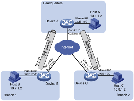
Table 1 Interface and IP address assignment
|
Device |
Interface |
IP address |
Device |
Interface |
IP address |
|
Device A |
Vlan-int 10 |
191.2.1.1/24 |
Device B |
Vlan-int 10 |
191.3.1.1/24 |
|
|
Vlan-int 20 |
10.1.1.1/24 |
|
Vlan-int 20 |
10.7.1.1/24 |
|
|
Tunnel 1 |
10.5.1.1/24 |
|
Tunnel 1 |
10.5.1.2/24 |
|
|
Tunnel 2 |
10.6.1.1/24 |
|
|
|
|
Device C |
Vlan-int 10 |
191.4.1.1/24 |
|
|
|
|
|
Vlan-int 20 |
10.8.1.1/24 |
|
|
|
|
|
Tunnel 2 |
10.6.1.2/24 |
|
|
|
Restrictions and guidelines
Encapsulated packets cannot be forwarded on Layer 3 according to the destination IP addresses and routing tables. You must create a service loopback group of the tunnel service type to loop encapsulated packets back to the forwarding module for Layer 3 forwarding.
Procedures
# Configure an IPv4 routing protocol on the gateways so that the gateways can reach one another. (Details not shown.)
Configuring Device A
# Configure an IP address for VLAN-interface 10.
<DeviceA> system-view
[DeviceA] vlan 10
[DeviceA-vlan10] port ten-gigabitethernet 1/0/1
[DeviceA-vlan10] quit
[DeviceA] interface vlan-interface 10
[DeviceA-Vlan-interface10] ip address 191.2.1.1 255.255.255.0
[DeviceA-Vlan-interface10] quit
# Configure other interfaces in the same way VLAN-interface 10 is configured. (Details not shown.)
# Create service loopback group 1, and specify its service type as tunnel.
[DeviceA] service-loopback group 1 type tunnel
# Add Ten-GigabitEthernet 1/0/3 to service loopback group 1.
[DeviceA] interface ten-gigabitethernet 1/0/3
[DeviceA-Ten-GigabitEthernet1/0/3] port service-loopback group 1
[DeviceA-Ten-GigabitEthernet1/0/3] quit
# Create tunnel interface Tunnel 1, and specify the tunnel mode as GRE/IPv4.
[DeviceA] interface tunnel 1 mode gre
# Configure an IP address for tunnel interface Tunnel 1.
[DeviceA-Tunnel1] ip address 10.5.1.1 24
# Configure the source interface of Tunnel 1 as VLAN-interface 10.
[DeviceA-Tunnel1] source vlan-interface 10
# Configure the destination address of Tunnel 1 as the IP address of VLAN-interface 10 on Device B.
[DeviceA-Tunnel1] destination 191.3.1.1
[DeviceA-Tunnel1] quit
# Create tunnel interface Tunnel 2, and specify the tunnel mode as GRE/IPv4.
[DeviceA] interface tunnel 2 mode gre
# Configure an IP address for tunnel interface Tunnel 2.
[DeviceA-Tunnel2] ip address 10.6.1.1 24
# Configure the source interface of Tunnel 2 as VLAN-interface 10.
[DeviceA-Tunnel2] source vlan-interface 10
# Configure the destination address of Tunnel 2 as the IP address of VLAN-interface 10 on Device C.
[DeviceA-Tunnel2] destination 191.4.1.1
[DeviceA-Tunnel2] quit
# Configure the OSPF router ID as 10.6.1.1.
[DeviceA] router id 10.6.1.1
# Enable OSPF process 1.
[DeviceA] ospf 1
# Create OSPF area 0.
[DeviceA-ospf-1] area 0
# Enable OSPF on interfaces whose primary IP addresses are on network 10.1.1.0/24, 10.5.1.0/24, or 10.6.1.0/24 in area 0.
[DeviceA-ospf-1-area-0.0.0.0] network 10.1.1.0 0.0.0.255
[DeviceA-ospf-1-area-0.0.0.0] network 10.5.1.0 0.0.0.255
[DeviceA-ospf-1-area-0.0.0.0] network 10.6.1.0 0.0.0.255
Configuring Device B
# Configure an IP address for VLAN-interface 10.
<DeviceB> system-view
[DeviceB] vlan 10
[DeviceB-vlan10] port ten-gigabitethernet 1/0/1
[DeviceB-vlan10] quit
[DeviceB] interface vlan-interface 10
[DeviceB-Vlan-interface10] ip address 191.3.1.1 255.255.255.0
[DeviceB-Vlan-interface10] quit
# Configure other interfaces in the same way VLAN-interface 10 is configured. (Details not shown.)
# Create service loopback group 1, and specify its service type as tunnel.
[DeviceB] service-loopback group 1 type tunnel
# Add Ten-GigabitEthernet 1/0/3 to service loopback group 1.
[DeviceB] interface ten-gigabitethernet 1/0/3
[DeviceB-Ten-GigabitEthernet1/0/3] port service-loopback group 1
[DeviceB-Ten-GigabitEthernet1/0/3] quit
# Create tunnel interface Tunnel 1, and specify the tunnel mode as GRE/IPv4.
[DeviceB] interface tunnel 1 mode gre
# Configure an IP address for tunnel interface Tunnel 1.
[DeviceB-Tunnel1] ip address 10.5.1.2 24
# Configure the source interface of Tunnel 1 as VLAN-interface 10.
[DeviceB-Tunnel1] source vlan-interface 10
# Configure the destination address of Tunnel 1 as the IP address of VLAN-interface 10 on Device A.
[DeviceB-Tunnel1] destination 191.2.1.1
[DeviceB-Tunnel1] quit
# Configure the OSPF router ID as 10.7.1.1.
[DeviceB] router id 10.7.1.1
# Enable OSPF process 1.
[DeviceB] ospf 1
# Create OSPF area 0.
[DeviceB-ospf-1] area 0
# Enable OSPF on interfaces whose primary IP addresses are on network 10.7.1.0/24 or 10.5.1.0/24 in area 0.
[DeviceB-ospf-1-area-0.0.0.0] network 10.7.1.0 0.0.0.255
[DeviceB-ospf-1-area-0.0.0.0] network 10.5.1.0 0.0.0.255
Configuring Device C
# Configure an IP address for VLAN-interface 10.
<DeviceC> system-view
[DeviceC] vlan 10
[DeviceC-vlan10] port ten-gigabitethernet 1/0/1
[DeviceC-vlan10] quit
[DeviceC] interface vlan-interface 10
[DeviceC-Vlan-interface10] ip address 191.4.1.1 255.255.255.0
[DeviceC-Vlan-interface10] quit
# Configure other interfaces in the same way VLAN-interface 10 is configured. (Details not shown.)
# Create service loopback group 1, and specify its service type as Tunnel.
[DeviceC] service-loopback group 1 type tunnel
# Add Ten-GigabitEthernet 1/0/3 to service loopback group 1.
[DeviceC] interface ten-gigabitethernet 1/0/3
[DeviceC-Ten-GigabitEthernet1/0/3] port service-loopback group 1
[DeviceC-Ten-GigabitEthernet1/0/3] quit
# Create tunnel interface Tunnel 2, and specify the tunnel mode as GRE/IPv4.
[DeviceC] interface tunnel 2 mode gre
# Configure an IP address for tunnel interface Tunnel 2.
[DeviceC-Tunnel2] ip address 10.6.1.2 24
# Configure the source interface of Tunnel 2 as VLAN-interface 10.
[DeviceC-Tunnel2] source vlan-interface 10
# Configure the destination address of Tunnel 2 as the IP address of VLAN-interface 10 on Device A.
[DeviceC-Tunnel2] destination 191.2.1.1
[DeviceC-Tunnel2] quit
# Configure the OSPF router ID as 10.8.1.1.
[DeviceC] router id 10.8.1.1
# Enable OSPF process 1.
[DeviceC] ospf 1
# Create OSPF area 0.
[DeviceC-ospf-1] area 0
# Enable OSPF on interfaces whose primary IP addresses are on network 10.8.1.0/24 or 10.6.1.0/24 in area 0.
[DeviceC-ospf-1-area-0.0.0.0] network 10.8.1.0 0.0.0.255
[DeviceC-ospf-1-area-0.0.0.0] network 10.6.1.0 0.0.0.255
Verifying the configuration
# Verify that Host A can ping Host B successfully.
C:\> ping 10.7.1.2
Pinging 10.7.1.2 with 32 bytes of data:
Reply from 10.7.1.2: bytes=32 time=19ms TTL=253
Reply from 10.7.1.2: bytes=32 time<1ms TTL=253
Reply from 10.7.1.2: bytes=32 time<1ms TTL=253
Reply from 10.7.1.2: bytes=32 time<1ms TTL=253
Ping statistics for 10.7.1.2:
Packets: Sent = 4, Received = 4, Lost = 0 (0% loss),
Approximate round trip times in milli-seconds:
Minimum = 0ms, Maximum = 19ms, Average = 4ms
# Verify that Host A can ping Host C successfully.
C:\> ping 10.8.1.2
Pinging 10.8.1.2 with 32 bytes of data:
Reply from 10.8.1.2: bytes=32 time=18ms TTL=253
Reply from 10.8.1.2: bytes=32 time<1ms TTL=253
Reply from 10.8.1.2: bytes=32 time<1ms TTL=253
Reply from 10.8.1.2: bytes=32 time<1ms TTL=253
Ping statistics for 10.8.1.2:
Packets: Sent = 4, Received = 4, Lost = 0 (0% loss),
Approximate round trip times in milli-seconds:
Minimum = 0ms, Maximum = 19ms, Average = 4ms
# Verify that Host B can ping Host C successfully.
C:\> ping 10.8.1.2
Pinging 10.8.1.2 with 32 bytes of data:
Reply from 10.8.1.2: bytes=32 time=20ms TTL=251
Reply from 10.8.1.2: bytes=32 time<1ms TTL=251
Reply from 10.8.1.2: bytes=32 time<1ms TTL=251
Reply from 10.8.1.2: bytes=32 time<1ms TTL=251
Ping statistics for 10.8.1.2:
Packets: Sent = 4, Received = 4, Lost = 0 (0% loss),
Approximate round trip times in milli-seconds:
Minimum = 0ms, Maximum = 19ms, Average = 4ms
Configuration files
· Device A:
#
service-loopback group 1 type tunnel
#
vlan 10
#
vlan 20
#
interface Vlan-interface10
ip address 191.2.1.1 255.255.255.0
#
interface Vlan-interface20
ip address 10.1.1.1 255.255.255.0
#
interface Ten-GigabitEthernet1/0/1
port link-mode bridge
port access vlan 10
#
interface Ten-GigabitEthernet1/0/2
port link-mode bridge
port access vlan 20
#
interface Ten-GigabitEthernet1/0/3
port link-mode bridge
port service-loopback group 1
#
interface Tunnel1 mode gre
source vlan-interface10
destination 191.3.1.1
ip address 10.5.1.1 255.255.255.0
#
interface Tunnel2 mode gre
source vlan-interface10
destination 191.4.1.1
ip address 10.6.1.1 255.255.255.0
#
router id 10.6.1.1
#
ospf 1
area 0.0.0.0
network 10.1.1.0 0.0.0.255
network 10.5.1.0 0.0.0.255
network 10.6.1.0 0.0.0.255
#
· Device B:
#
service-loopback group 1 type tunnel
#
vlan 10
#
vlan 20
#
interface Vlan-interface10
ip address 191.3.1.1 255.255.255.0
#
interface Vlan-interface20
ip address 10.7.1.1 255.255.255.0
#
interface Ten-GigabitEthernet1/0/1
port link-mode bridge
port access vlan 10
#
interface Ten-GigabitEthernet1/0/2
port link-mode bridge
port access vlan 20
#
interface Ten-GigabitEthernet1/0/3
port link-mode bridge
port service-loopback group 1
#
interface Tunnel1 mode gre
source Vlan-interface10
destination 191.2.1.1
ip address 10.5.1.2 255.255.255.0
#
router id 10.7.1.1
#
ospf 1
area 0.0.0.0
network 10.7.1.0 0.0.0.255
network 10.5.1.0 0.0.0.255
#
· Device C:
#
service-loopback group 1 type tunnel
#
vlan 10
#
vlan 20
#
interface Vlan-interface10
ip address 191.4.1.1 255.255.255.0
#
interface Vlan-interface20
ip address 10.8.1.1 255.255.255.0
#
interface Ten-GigabitEthernet1/0/1
port link-mode bridge
port access vlan 10
#
interface Ten-GigabitEthernet1/0/2
port link-mode bridge
port access vlan 20
#
interface Ten-GigabitEthernet1/0/3
port link-mode bridge
port service-loopback group 1
#
interface Tunnel2 mode gre
source Vlan-interface10
destination 191.2.1.1
ip address 10.6.1.2 255.255.255.0
#
router id 10.8.1.1
#
ospf 1
area 0.0.0.0
network 10.8.1.0 0.0.0.255
network 10.6.1.0 0.0.0.255
#
Related documentation
· H3C S7500E Switch Series Layer 3—IP Routing Command Reference-R757X
· H3C S7500E Switch Series Layer 3—IP Routing Configuration Guide-R757X
· H3C S7500E Switch Series Layer 3—IP Services Command Reference-R757X
· H3C S7500E Switch Series Layer 3—IP Services Configuration Guide-R757X
