- Table of Contents
- Related Documents
-
| Title | Size | Download |
|---|---|---|
| 01-Hardware Information and Specifications | 867.70 KB |
1 Product models and system features
3 FRUs and compatibility matrixes
Management Ethernet port status LED
1 Product models and system features
Product models
The H3C S6850-56HF-CP cold-plate liquid-cooled Ethernet switch is a high-density, intelligent 25G access switch developed by H3C for cloud data centers and cloud computing networks. It offers 25GE and 100GE port configurations and boasts powerful hardware forwarding capabilities along with abundant data center features. The H3C S6850 series include the following models:
|
Product series |
Product model |
Product code |
|
H3C S6850 series |
S6850-56HF-CP |
LS-6850-56HF-CP |
|
|
NOTE: · For product selection information, see the switch data sheet: https://www.h3c.com/cn/Products_And_Solution/InterConnect/Products/Switches/. To view the switch product lifecycle management announcement, access https://www.h3c.com/cn/Service/Policy_Trends/Product_Periods/Termination_Notice/Switches_Series/ · To view the product and software compatibility, see the release notes. |
System features
Table1-1 Product specifications
|
Item |
LS-6850-56HF-CP |
|
Physical specifications |
|
|
Dimensions (H × W × D) |
44 × 440 × 400 mm (1.73 × 17.32 × 15.75 in) |
|
Dimensions (including packaging) (H × W × D) |
180 × 638 × 576 mm (7.09 × 25.12 × 22.68 in) |
|
Weight (fully equipped with power modules and fan trays) |
≤ 9 kg (19.84 lb) |
|
Processor |
Quad-core, 2.2 GHz |
|
Technical specifications |
|
|
DRAM Memory |
4 GB |
|
NOR Flash |
2 × 32 MB (32 MB primary and 32 MB backup) |
|
NAND Flash |
EMMC 4G |
|
Interface type and quantity |
|
|
Console ports |
Serial console port: 1 |
|
Management Ethernet ports |
Management Ethernet copper port: 1 |
|
USB ports |
USB 2.0 port: 1 |
|
SFP28 ports |
48 |
|
QSFP28 ports |
8 |
|
IRF physical ports |
QSFP28 port can act as an IRF physical port |
|
Fan tray and power module slots |
|
|
Fan tray slots |
4 |
|
Power module slots |
2 |
|
Power supply specifications |
|
|
Power input type |
AC input |
|
Overall power consumption |
|
|
Typical power consumption Collection standard: Fully-equipped with cables, 50% load |
· Single AC input: 143 W · Dual AC inputs: 150 W |
|
Maximum power consumption Collection standard: Full-equipped with transceiver modules, 100% load |
· Single AC input: 424 W · Dual AC inputs: 429 W |
|
Overall thermal consumption |
|
|
Thermal consumption (typical) |
Single AC input/Dual AC inputs: 498 BTU/hr |
|
Thermal consumption (max) |
1464 BTU/hr |
|
Heat dissipation |
|
|
Heat dissipation method |
Cold plate-based liquid-cooling and air cooling |
|
Air cooling ventilation aisles |
Front-to-back or back-to-front airflow (based on the installed fans) |
|
Reliability and availability |
|
|
Power redundancy |
1+1 redundancy |
|
Fan tray redundancy |
Four fan trays fully equipped |
|
Hot swapping |
Supported |
|
Mean Time Between Failures (MTBF) (years) |
78.7 |
|
Mean Time To Repair (MTTR) (hours) |
1 |
|
Availability |
99.999927% |
|
Environment specifications |
|
|
Sound pressure level at 27°C (80.6°F) |
65.5 dB(A) |
|
Altitude |
–60 to +5000 m (–196.85 to 16404.20 ft) |
|
Operating temperature |
0ºC to 40ºC (32ºF to 113ºF) NOTE: The allowed maximum temperature decreases by 0.33 °C (32.59°F) as the altitude increases by 100 m (328.08 ft) from 0 m (0 ft). |
|
Storage temperature |
–40ºC to +70ºC (–40°F to +158°F) |
|
Relative humidity (non-condensing) |
5% to 90% |
|
Certification |
|
|
Certification |
· Compliant safety standards · Compliant EMC standards · Compliant environmental and eco-friendly standards |
|
Cooling connector parameters |
|
|
Quick connector type for liquid inlet and outlet |
· UQD02-T04BSSJEE · UQD02-T04RSSJEE |
|
Water inlet temperature |
≤ 45ºC (113°F) |
|
Water system pressure drop (Bar) |
≤ 40 kPa |
|
Water system flow rate (L/min) |
≤ 1.5 L/min |
2 Chassis views
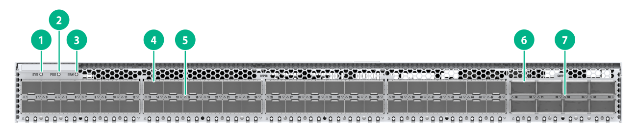
Figure2-1 LS-6850-56HF-CP front panel
|
(1) System status LED (SYS) |
(2) Power supply status LED (PSU) |
|
(3) Fan tray status LED (FAN) |
(4) SFP28 Ethernet fiber port |
|
(5) SFP28 port status LED |
(6) QSFP28 Ethernet fiber port |
|
(7) QSFP28 port status LED |
|
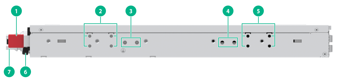
Figure2-2 LS-6850-56HF-CP left panel
|
(1) Power module latch |
(2) Mounting bracket installation position at the power module side |
|
(3) Switch grounding point 1 |
(4) Switch grounding point 2 |
|
(5) Mounting bracket installation position at the port side |
(6) Power module handle |
|
(7) Liquid cooling quick-connect male connector |
|
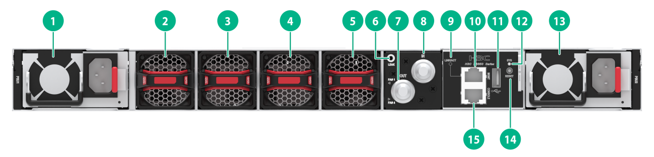
Figure2-3 LS-6850-56HF-CP rear panel
|
(1) Power module 1 |
(2) Fan tray 1 |
|
(3) Fan tray 2 |
(4) Fan tray 3 |
|
(5) Fan tray 4 |
(6) Water leak LED |
|
(7) Quick-connect male connector for liquid cooling outlet |
(8) Quick-connect male connector for liquid cooling inlet |
|
(9) Management Ethernet copper port LED (LINK/ACT) |
(10) Management Ethernet copper port |
|
(11) USB port |
(12) System status LED (SYS) |
|
(13) Power module 2 |
(14) RESET button |
|
(15) Serial console port |
|
|
|
NOTE: · The rear panel of the LS-6850-56HF-CP has two power module slots. By default, no power modules are installed. Slot PWR1 is empty, and slot PWR2 comes with a filler panel. You can install one or two power modules for the switch as needed. In the figure, two SW-A-PSR550-12A-B AC power modules are installed. · The rear panel of the LS-6850-56HF-CP has four fan tray slots. By default, all the four slots are empty. You must install four fan trays of the same model. In this figure, the switch is fully equipped with FAN-40B-1-C fan trays. · The LS-6850-56HF-CP supports delivery with fan trays and power modules. If you need the purchased modules installed on the device before shipping, contact H3C marketing personnel in advance to make a note on the order. · The LS-6850-56HF-CP provides a RESET button on the back panel for you to immediately reboot the device. |
3 FRUs and compatibility matrixes
The S6850-56HF-CP cold plate liquid-cooled Ethernet switch features a modular design. See Table3-1 for details.
Table3-1 FRUs and compatibility matrix for the S6850-56HF-CP
|
Removable component model |
Component code |
LS-6850-56HF-CP |
|
SW-A-PSR550-12A-B |
0231AKX6 |
Yes |
|
FAN-40B-1-C |
9803A00F |
Yes |
|
FAN-40F-1-D |
0231AKLC |
Yes |
|
|
NOTE: · One power supply can meet the power requirement of the switch. You can install two power supplies on the switch for 1+1 redundancy. · To ensure device heat dissipation, fully install fan trays of the same model. |
4 Removable power modules
The S6850-56HF-CP cold plate liquid-cooled Ethernet switch features a modular design.
|
|
WARNING! The S6850-56HF-CP supports the replacement of redundant backup power modules without powering off the device. To avoid device damage or even bodily injury, before removing or installing a power module, make sure the power module has no power input. |
Appearance
Figure4-1 SW-A-PSR550-12A-B power module
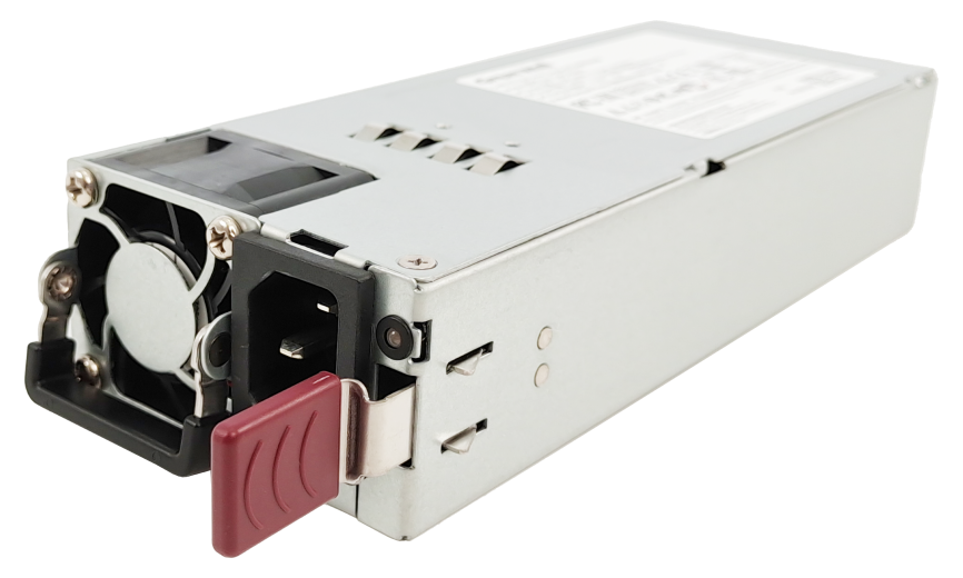
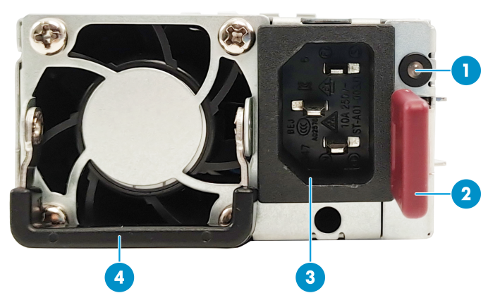
Figure4-2 Front panel of the SW-A-PSR550-12A-B power module
|
(1) Power module status LED |
(2) Power module latch |
|
(3) Power input receptacle |
(4) Handle |
For more information about LED description, see "Power module status LED."
Functions
The SW-A-PSR550-12A-B is an AC input or high-voltage DC input and DC output power module. It provides a maximum output of 550 W. The main features are as shown in Table4-1.
Table4-1 SW-A-PSR550-12A-B power supply features
|
Feature |
Description |
|
Protection function |
The power supply provides protection against input overcurrent, input undervoltage, output overvoltage, output shortcircuit, and overtemperature conditions. |
|
Support for redundancy |
Multiple power supplies can be connected in parallel to achieve N+1 or N+N redundancy and load balancing. |
|
Support for hot swapping |
You can remove one of the power supplies in redundancy when the switch is operating. |
Technical specifications
Table4-2 SW-A-PSR550-12A-B specifications
|
Item |
Specifications |
|
Dimensions (H × W × D, including the handle) |
73.5 × 185 × 40 mm (2.89 × 7.28 × 1.57 in) |
|
Weight |
0.75 kg (1.65 lb) |
|
Rated input voltage range |
100 to 240 VAC @ 50/60Hz |
|
Max input voltage range |
90 to 264 VAC |
|
High voltage DC rated input voltage range |
240 VDC |
|
High voltage DC maximum input voltage range |
190 to 310 VDC |
|
Rated input current |
7.0A Max @ 100 to 240 VAC 3.5A Max @ 240 VDC |
|
Rated output current |
45A |
|
Rated output voltage |
12V |
|
Rated output power |
550W |
|
Fuse rated current |
10A |
5 Removable fan trays
|
|
CAUTION: The S6850-56HF-CP has multiple fan tray slots. To ensure proper heat dissipation, follow these restrictions and guideline: · Fully install fan trays of the same model. If a fan tray slot is empty or the installed fan trays are of different models, the device will display a prompt and prevent power-up. · During device operation, make sure all module slots are filled. You must install the corresponding module or filler panel in each module slot. · During the device operation, if multiple fan trays fail, do not remove several fan trays at the same time when replacing them. Replace the faulty fan trays one by one, and make sure the replacement time for a single fan tray does not exceed 3 minutes. |
The S6850-56HF-CP supports the following fan trays: FAN-40B-1-C and FAN-40F-1-D.
Appearance

For more information about LED description, see Table7-6.
Functions
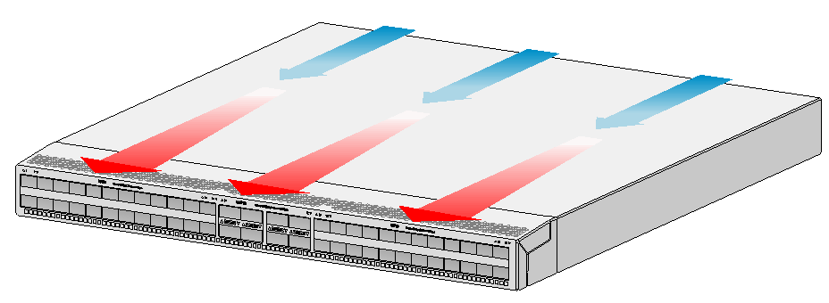
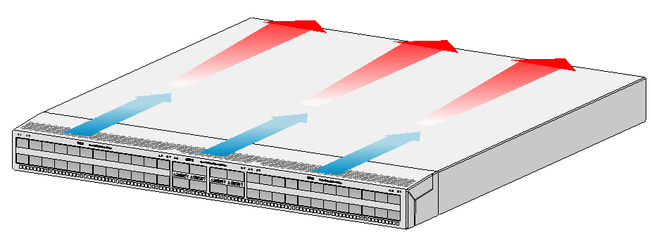
The FAN-40B-1-C fan tray provides port-to-power module airflow and the FAN-40F-1-D fan tray provides power supply-to-port airflow. The fan tray is characterized by its compact size, rapid heat dissipation, and hot-swappable feature. It can also automatically adjust the fan speed according to the device temperature, providing strong cooling capabilities for the device.
Technical specifications
|
Item |
Fan-40B-1-C specifications |
FAN-40F-1-D specifications |
|
Dimensions (H × W × D, including the handle) |
40 × 40 × 136 mm (1.57 × 1.57 × 5.35 in) |
|
|
Weight |
0.12 kg (0.26 lb) |
|
|
Airflow direction |
Air outlet from the fan tray panel |
Air inlet from the fan tray panel |
|
Max fan speed |
29000 RPM |
|
|
Maximum air flow rate |
38 CFM |
|
|
Input voltage |
12V |
|
|
Maximum power consumption |
60W |
50.4W |
6 Ports
|
|
NOTE: · As a best practice, use H3C transceiver modules and cables on this series of switches. · The H3C transceiver modules and cables are subject to change over time. For the most recent list of H3C transceiver modules and cables, contact your H3C Support or marketing staff. · For the specifications of H3C transceiver modules and cables, see H3C Transceiver Modules User Guide. |
Console port
The S6850-56HF-CP provides a console port. See Table6-1 for details.
Table6-1 Console port specifications
|
Item |
Description |
|
Connector type |
RJ-45 |
|
Compliant standard |
EIA/TIA-232 |
|
Operating mode |
Duplex Universal Asynchronous Receiver/Transmitter (UART) |
|
Transmission baud rate |
9600 bps (default) to 115200 bps |
|
Support services |
· Provides connection to an ASCII terminal. · Provides connection to the serial port of a local terminal (for example, a PC) running a terminal emulation program |
Management Ethernet port
The S6850-56HF-CP provides a management Ethernet copper port. You can connect the port to a local PC for software loading and debugging or to a remote management station for remote management.
Table6-2 Management Ethernet port specifications
|
Item |
Description |
|
Connector type |
RJ-45/LC |
|
Number of connectors |
One 10/100/1000BASE-T management port |
|
Compliant standard |
Management 10/100/1000BASE-T ports: IEEE802.3ab |
|
Port transmission rate |
Management 10/100/1000BASE-T ports: · 10M full duplex/half duplex · 100M full duplex/half duplex · 1000M full duplex · MDI/MDI-X, auto-sensing |
|
Interface cable media and maximum transmission distance |
Management 10/100/1000BASE-T interface: Copper ports with Category 5 unshielded twisted pair (UTP), supporting a transmission distance of 100 meters. |
|
Functions and services |
For device software update and network management |
USB port
The S6850-56HF-CP provides a USB 2.0 port that complies with the OHCI standard and supports a 480Mbps uploading and downloading rate. Through this interface, users can interact with the Flash file system on the switch, for example, uploading or downloading application files or configuration files.
|
|
IMPORTANT: · Due to compatibility and driver differences among USB devices of different manufacturers, H3C does not guarantee that USB devices from all manufacturers will function normally on this series of switches. If a USB device is not functioning properly, it is not due to a switch fault. Try using a USB device from a different manufacturer. · The USB port on the switch is designed to output current strictly in accordance with the USB 2.0 standard. Use USB storage devices that fully comply with USB 2.0 standards. If the USB storage device you use does not fully comply with the USB 2.0 standard, the USB port of this switch might fail to recognize the USB device. |
QSFP28 ports
Table6-3 QSFP28 port description
|
Item |
Description |
|
Port name |
40GE/100GE QSFP28 fiber port |
|
Product support status |
The front panel provides eight QSFP28 ports |
|
Connector type |
LC/MPO |
|
Description |
The 40GE/100GE QSFP28 Ethernet fiber ports are mainly used for transmitting and receiving 40GE/100GE fiber port services. |
|
Compliant standard |
IEEE802.3ba |
|
Fiber port properties |
Depends on the transceiver modules or cables installed |
|
Operating mode |
Full Duplex |
|
Available transceiver modules and cables |
· 100G QSFP28 module · 100G QSFP28 cable · 100G QSFP28 optical fiber (AOC) · 100G QSFP28 to 4*25G SFP28 cable · 40G QSFP+ module · 40G QSFP+ cable · 40G QSFP+ optical fiber (AOC) · 40G QSFP+ to 4*10G SFP+ cable · You can install a QSFP+ to SFP+ adapter to support 10G SFP+ modules. Before using this adapter, manually execute the using tengige command on the port where the adapter is to be installed to split the interface. NOTE: · For more information about the transceiver modules and cables supported by a QSFP28 port, see H3C S6850 & S9850 Switch Series Transceiver Module Compatibility Matrixes. · The QSFP-40G-SR4-MM850 and QSFP-40G-CSR4-MM850 modules both support the 1-to-4 port split function, enabling interconnection between one 100G QSFP28 port and four 10G SFP+ ports. The connected QSFP+ and SFP+ modules must have matching specifications, including center wavelength and fiber optic type. |
|
Split support status |
Support splitting into four 25G ports or four 10G ports. |
|
Other restrictions and guidelines |
When using a 100G DAC cable to connect a 100G port on the device to certain Intel network cards, for example, Intel (rainbow) Eth E810-CQDA2, the port might fail to come up. As a best practice, use an AOC optical fiber or an transceiver module for connections with Intel network cards. |
SFP28 ports
Table6-4 SFP28 port description
|
Item |
Description |
|
Port name |
25GE SFP28 Ethernet fiber port |
|
Product support status |
The front panel provides 48 SFP28 ports. |
|
Connector type |
LC |
|
Description |
The 25GE SFP28 Ethernet fiber ports support autosensing to 10GE/1GE and is primarily used for transmitting and receiving signals for 25GE/10GE/1GE Ethernet optical services. |
|
Compliant standard |
IEEE802.3by |
|
Fiber port properties |
Depends on the transceiver modules or cables installed |
|
Operating mode |
· When using an SFP28 cable or SFP+ cable to connect an SFP28 port to the peer end, if the peer end does not support rate and duplex auto-negotiation, execute the speed and duplex full commands on both ends. For the port to come up, make sure the rate configured by the speed command must match the rate of the transceiver module. · When you use an SFP module other than SFP-GE-T and SFP-GE-T-D on a SFP28 port to establish a connection, disable autonegotiation on the remote end. · For more information about configuration restrictions and guidance for SFP28 ports, see Layer 2 — LAN Switching Configuration Guide. |
|
Available transceiver modules and cables |
Supports 25G SFP28 modules/cables, 10G SFP+ modules/cables, and 1G SFP modules NOTE: · For more information about the transceiver modules and cables supported by a SFP28 port, see H3C S6850 & S9850 Switch Series Transceiver Module Compatibility Matrixes. · Use BIDI optical modules in pairs. For example, if one end uses SFP-XG-LX-SM1270-BIDI, use FP-XG-LX-SM1330-BIDI at the other end. · The maximum transmission distance of the SFP-25G-SR-MM850 module varies by the enabling status of the FEC negotiation feature. For more information, see Table6-5. For more information about FEC negotiation, see Layer 2—LAN Switching Configuration Guide. |
|
Other restrictions and guidelines |
You can use a maximum of four long-distance SFP+ transceiver modules of the following models on a device: · SFP-XG-LH40-SM1550 · SFP-XG-LH40-SM1550-D · SFP-XG-LH80-SM1550 · SFP-XG-LH80-SM1550-D Only the 1G rate is supported on a port installed with the SFP-GE-T or SFP-GE-T-D module. When a device uses the SFP-GE-T/SFP-GE-T-D module to connect to the peer end, the peer port might come online before the local port comes online, resulting in packet loss. As a best practice to avoid the issue mentioned above, use dynamic aggregation if you are to aggregate the links between the device and a remote device. |
Table6-5 Maximum transmission distance of the SFP-25G-SR-MM850
|
Transceiver module/cable name |
Central wavelength (nm) |
Connector |
Cable specifications |
Mode bandwidth (MHz*km) |
Max transmission distance |
|
SFP-25G-SR-MM850 |
850 |
LC |
50/125µm multimode fiber |
2000 |
FEC negotiation disabled: 30 m (98.43 ft) FEC negotiation disabled: 70 m (229.66 ft) |
|
4700 |
FEC negotiation disabled: 40 m (131.23 ft) FEC negotiation disabled: 100 m (328.08 ft) |
7 LEDs
System status LED
Through the system status LED, you can preliminarily determine the working state of the switch. For more information, see Table7-1.
Table7-1 Description of the system status LED
|
LED |
Status |
Description |
|
SYS |
Steady green |
The switch has been normally started |
|
Flashing green |
The switch is performing power-on self test (POST). |
|
|
Steady red |
The switch has failed POST or the switch is faulty. |
|
|
Flashing red |
Some ports failed the power-on self-test (POST) and their functionality fails. NOTE: When the Bootware boot mode is set to Fast Mode, the system does not perform POST. |
|
|
Flashing blue (3 Hz) |
UID LED NOTE: The LED is on to help device location after you execute the locator blink blink-time command on the device. |
|
|
Off |
The switch is powered off or has not started up correctly |
QSFP28 port status LED
Table7-2 Description of the QSFP28 port status LED
|
Status |
Description |
|
Steady green |
A module has been installed. The port operates in 100G mode, and the port link is up. |
|
Flashing green |
The port is sending or receiving data at 100G. |
|
Steady yellow |
A module has been installed. The port operates in 10G, 25G, or 10G mode, and the port link is up. |
|
Flashing yellow (3 Hz) |
The port operates in 10G, 25G, or 40G mode and is receiving or transmitting data. |
|
Off |
No module has been installed or no link is present on the port. |
SFP28 port status LED
Table7-3 Description of the SFP28 port status LED
|
Status |
Description |
|
Steady green |
A module has been installed. The port operates with the highest rate, and the port link is up. |
|
Flashing green |
The port operates with the highest rate, and is receiving or sending data. |
|
Steady yellow |
A module has been installed. The port operates with the highest rate, and the port link is up. |
|
Flashing yellow (3 Hz) |
The port operates with the highest rate, and is receiving or sending data. |
|
Off |
No module has been installed or no link is present on the port. |
Management Ethernet port status LED
The S6850-56HF-CP provides one LINK/ACT status LED for the management Ethernet copper port. Through the status LED, you can preliminarily determine the working state of the management Ethernet port. For more information, see Table7-4.
Table7-4 Description of the management Ethernet port status LED
|
LED |
Status |
Description |
|
LINK/ACT |
Steady green |
The management Ethernet port operates at 10/100/1000 Mbps and the port link is up. |
|
Steady green, flashing yellow |
The port is in sending or receiving data. |
|
|
Off |
The management Ethernet port does not have a connection. |
Power module status LED
The SW-A-PSR550-12A-B provides a power LED at the panel to show the input and output state of the power module. For more information about the status of the LED, see Table7-5.
Table7-5 Description of the power module status LED
|
Status |
Description |
|
Steady green |
The power supply system is operating correctly. |
|
Flashing green (1 Hz) |
The power input is normal, and the system is not powered on and is in standby state. |
|
Flashing green (0.33Hz) |
The power module is in standby mode and not outputting power. |
|
Flashing green (2Hz) |
The power module is in firmware update state. |
|
Steady amber |
· The power module has experienced a critical fault. · The power module has no input, but the other power module has normal input. |
|
Flashing amber (1 Hz) |
The power module has triggered an alarm. |
|
Off |
The power module has no input. Possible reasons include: · The power cord connection fails. · The external power supply system has lost power. |
Fan tray alarm LED
Each fan tray has an alarm LED on the panel. For the meaning of the alarm LED on the FAN-40B-1-C/FAN-40F-1-D fan tray, see Table7-6.
Table7-6 Description of the fan tray alarm LED
|
Status |
Description |
|
Steady green |
The fan tray is running normally. |
|
Steady red |
The fan tray is abnormal. |
|
Off |
The fan tray is not properly inserted or powered. |
Power status LED
The LS-6850-56HF-CP provides a power status LED on the panel. You can view the LED to identify the operating status of the power modules in the chassis. For more information, see Table7-7.
Table7-7 Description of the power status LED
|
LED |
Status |
Description |
|
PSU |
Steady green |
The power modules are running normally. |
|
Steady yellow |
The number of faulty power modules or absent power modules is 1. |
|
|
Off |
The number of faulty power modules or absent power modules is 2. |
Fan tray status LED
The LS-6850-56HF-CP provides a fan tray status LED on the panel. You can view the LED to identify the operating status of the fan trays in the chassis. For more information, see Table7-8.
Table7-8 Description of the fan tray status LED
|
LED |
LED status |
Description |
|
FAN |
Steady green |
The fan tray is running normally. |
|
Steady yellow |
The number of faulty fan trays or absent fan trays is 1. |
|
|
Steady red |
The number of faulty fan trays or absent fan trays is equal to or larger than 2. |
Water leak LED
The LS-6850-56HF-CP provides one water leak LED on the panel. You can view the LED to identify the water leak status. For more information, see Table7-8.
Table7-9 Water leak LED status and description
|
LED |
LED status |
Description |
|
LEAK |
Steady green |
The liquid cooling system is running normally. |
|
Steady red |
A leak alarm has been triggered, or an alarm indicating a break in leak detection is present. |
8 Cooling system
The S6850-56HF-CP cold plate liquid-cooled Ethernet switch employs both a cold plate and fan trays to remove all heat from the switch and thus significantly reduce the number of required air conditioners.
· The liquid cooling system uses a cold plate to directly exchange heat with the casings of high-power consumption components such as chips. It utilizes a CDU to provide circulation power, allowing the flowing water to carry the heat out of the equipment room.
· The liquid cooling system provides circulation power through the switch's own cooling fans, and with powerful cooling fans, it removes the heat from low-power consumption components within the switch from the equipment room.
For more information about the cold plate-based liquid-cooled system of the S6850-56HF-CP Ethernet switch, see H3C Cold Plate-Based Liquid-Cooled System User Guide.
Table8-1 Fan tray cooling system
|
Device model |
Optional fan tray |
Airflow direction |
|
S6850-56HF-CP |
FAN-40F-1-D |
From the power module side to the port side
|
|
FAN-40B-1-C |
From the port side to the power module side
|