- Released At: 02-04-2024
- Page Views:
- Downloads:
- Table of Contents
- Related Documents
-
Contents
1 Product models and technical specifications
3 FRUs and compatibility matrixes
650W AC power module (LSVM1AC650)
650W DC power module (LSVM1DC650)
300W AC power module (LSVM1AC300)
300W DC power module (LSVM1DC300)
250W AC power modules (PSR250-12A and PSR250-12A1)
450W AC power modules (PSR450-12A, PSR450-12A1, and PSR450-12AHD)
450W DC power module (PSR450-12D)
LSWM1FWD0/LSWM1IPSD0/LSWM1ADED0
1/10GBASE-T autosensing Ethernet port
1/10GBASE-T autosensing Ethernet port LED
FC interface LEDs on the LSWM116FC, LSWM124XG2QFC, and LSWM18G24FC interface modules
1 Product models and technical specifications
Product models
The S6800 switch series includes the models in Table1-1.
|
Model |
Product code (PID) |
|
S6800-32Q |
· LS-6800-32Q · LS-6800-32Q-H1 |
|
S6800-54QF |
· LS-6800-54QF · LS-6800-54QF-H1 · LS-6800-54QF-H3 · LS-6800-54QF-H5 |
|
S6800-54QT |
· LS-6800-54QT · LS-6800-54QT-H1 · LS-6800-54QT-H3 |
|
S6800-54HF |
LS-6800-54HF |
|
S6800-54HT |
LS-6800-54HT |
|
S6800-2C |
· LS-6800-2C · LS-6800-2C-H1 |
|
S6800-2C-FC |
LS-6800-2C-H1-FC |
|
S6800-4C |
· LS-6800-4C · LS-6800-4C-H1 |
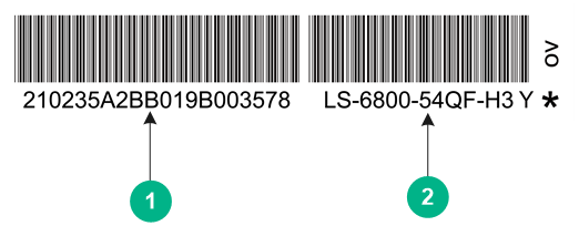
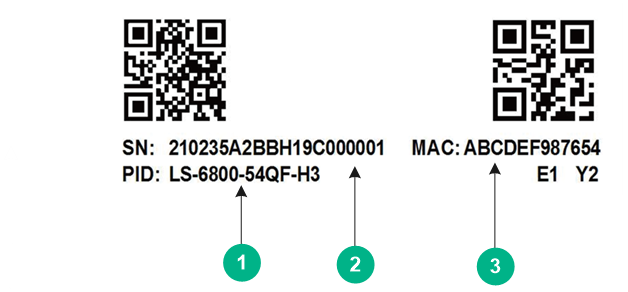
Switches of the same model but different PIDs might differ in hardware and software features. You can view the product code of a switch from the barcode product label (Figure1-1) or QR code product label (Figure1-2) on the rear panel or the top panel.
|
(1) Product serial number |
(2) Product code |
|
(1) Product code |
(2) Product serial number |
|
(3) MAC address |
|
Technical specifications
Table1-2 Technical specifications (1)
|
Item |
S6800-32Q |
S6800-54QF (LS-6800-54QF) S6800-54QF (LS-6800-54QF-H1) |
S6800-54QT (LS-6800-54QT) S6800-54QT (LS-6800-54QT-H1) |
|
Physical specifications |
|||
|
Dimensions (H × W × D, without package materials) |
43.6 × 440 × 660 mm (1.72 × 17.32 × 25.98 in) |
43.6 × 440 × 460 mm (1.72 × 17.32 × 18.11 in) |
43.6 × 440 × 660 mm (1.72 × 17.32 × 25.98 in) |
|
Dimensions (H × W × D, with package materials) |
825 × 565 × 190 mm (32.48 × 22.24 × 7.48 in) |
588 × 556 × 150 mm (23.15 × 21.89 × 5.91 in) |
825 × 565 × 190 mm (32.48 × 22.24 × 7.48 in) |
|
Weight (fully configured with power modules and fan trays) |
≤ 13 kg (28.66 lb) |
≤ 10 kg (22.05 lb) |
≤ 13 kg (28.66 lb) |
|
Technical specifications |
|||
|
Processor |
2 cores, 1 GHz |
2 cores, 1 GHz |
2 cores, 1 GHz |
|
DRAM memory |
4 GB |
2 GB |
2 GB |
|
NOR flash |
8 MB |
8 MB |
8 MB |
|
NAND flash |
1 GB |
512 MB |
512 MB |
|
Port types and quantity |
|||
|
Console ports |
· 1 × mini USB console port · 1 × serial console port |
1 × serial console port |
1 × serial console port |
|
Management Ethernet ports |
1 |
1 |
1 |
|
USB ports |
1 |
1 |
1 |
|
1/10GBASE-T autosensing Ethernet ports |
N/A |
N/A |
48 |
|
SFP+ ports |
N/A |
48 |
N/A |
|
QSFP+ ports |
32 |
6 |
6 |
|
IRF physical ports |
The following ports on the switch panel and expansion modules support IRF connection: · 10GBase-T Ethernet ports · SFP+ ports · QSFP28 ports · QSFP+ ports |
||
|
Fan tray and power module slots |
|||
|
Fan tray slots |
2 |
2 |
2 |
|
Power module slots |
2 |
2 |
2 |
|
Power module specifications |
|||
|
Power input |
AC input, DC input, and HVDC input |
||
|
Power specifications |
See "Removable power modules" |
||
|
Power consumption |
|||
|
Power consumption (static) |
LS-6800-32Q: · Single AC input: 175 W · Dual AC inputs: 190 W · Single DC input: 172 W · Dual DC inputs: 183 W LS-6800-32Q-H1: · Single AC input: 132 W · Dual AC inputs: 145 W · Single DC input: 128 W · Dual DC inputs: 142 W |
LS-6800-54QF · Single AC input: 114 W · Dual AC inputs: 121 W · Single DC input: 121 W · Dual DC inputs: 121 W LS-6800-54QF-H1: · Single AC input: 75 W · Dual AC inputs: 81 W · Single DC input: 72 W · Dual DC inputs: 80 W |
LS-6800-54QT: · Single AC input: 155 W · Dual AC inputs: 170 W · Single DC input: 160 W · Dual DC inputs: 180 W LS-6800-54QT-H1: · Single AC input: 135 W · Dual AC inputs: 150 W · Single DC input: 132 W · Dual DC inputs: 142 W |
|
Power consumption (fully configured) |
LS-6800-32Q: · Single AC input: 394 W · Dual AC inputs: 409 W · Single DC input: 398 W · Dual DC inputs: 399 W LS-6800-32Q-H1: · Single AC input: 291 W · Dual AC inputs: 301 W · Single DC input: 291 W · Dual DC inputs: 299 W |
LS-6800-54QF: · Single AC input: 208 W · Dual AC inputs: 213 W · Single DC input: 211 W · Dual DC inputs: 216 W LS-6800-54QF-H1: · Single AC input: 145 W · Dual AC inputs: 150 W · Single DC input: 141 W · Dual DC inputs: 145 W |
LS-6800-54QT: · Single AC input: 360 W · Dual AC inputs: 370 W · Single DC input: 365 W · Dual DC inputs: 380 W LS-6800-54QT-H1: · Single AC input: 260 W · Dual AC inputs: 270 W · Single DC input: 251 W · Dual DC inputs: 265 W |
|
Thermal consumption |
|||
|
Typical thermal consumption |
N/A |
N/A |
N/A |
|
Maximum thermal consumption |
· Single AC input: 1344.37 BTU/hr · Dual AC inputs: 1395.55 BTU/hr · Single DC input: 1358.02 BTU/hr · Dual DC inputs: 1361.43 BTU/hr |
LS-6800-54QF: · Single AC input: 709.72 BTU/hr · Dual AC inputs: 726.78 BTU/hr · Single DC input: 719.95 BTU/hr · Dual DC inputs: 737.01 BTU/hr LS-6800-54QF-H1: · Single AC input: 494.75 BTU/hr · Dual AC inputs: 511.82 BTU/hr · Single DC input: 481.11 BTU/hr · Dual DC inputs: 494.75 BTU/hr |
LS-6800-54QT: · Single AC input: 1228.36 BTU/hr · Dual AC inputs: 1262.48 BTU/hr · Single DC input: 1245.42 BTU/hr · Dual DC inputs: 1296.60 BTU/hr LS-6800-54QT-H1: · Single AC input: 887.15 BTU/hr · Dual AC inputs: 921.27 BTU/hr · Single DC input: 856.44 BTU/hr · Dual DC inputs: 904.21 BTU/hr |
|
Heat dissipation |
|||
|
Heat dissipation method |
Air cooling |
||
|
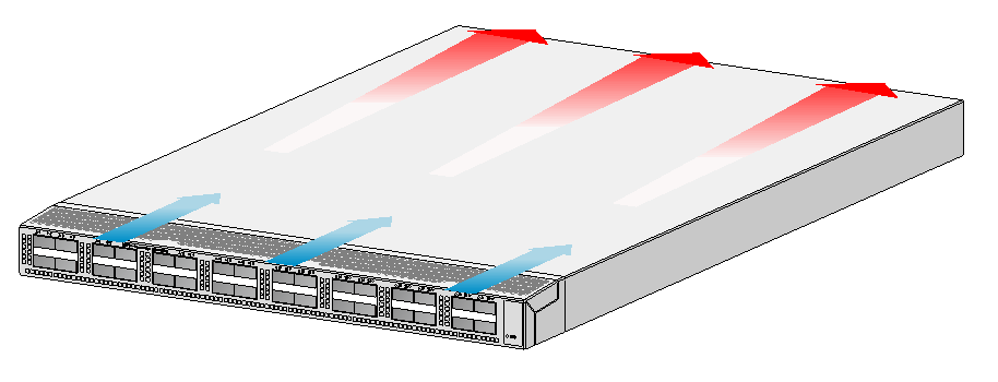
Ventilation aisle |
Front-to-rear airflow |
||
|
Reliability and availability |
|||
|
Power module redundancy |
1+1 |
1+1 |
1+1 |
|
Fan tray redundancy |
1+1 |
1+1 |
1+1 |
|
Hot swapping |
Power modules and fan trays are hot swappable. |
||
|
Mean Time Between Failure (MTBF) (year) |
32.32 |
63.12 |
64.8 |
|
Mean time to repair (MTTR) (hour) |
1 |
1 |
1 |
|
Availability |
99.999647% |
99.999977% |
99.99982% |
|
Environment specifications |
|||
|
Sound pressure level at 27°C (80.6°F) |
59.8 dB(A) |
61.8 dB(A) |
62.7 dB(A) |
|
Operating altitude |
–60 m to +5000 m (–196.85 ft to +16404.20 ft) The maximum acceptable temperature decreases by 0.33°C (32.59°F) for every 100 m (328.08 ft) increase in altitude from 0 m (0 ft). |
||
|
Storage altitude |
–60 m to +5000 m (–196.85 ft to +16404.20 ft) |
||
|
Operating temperature |
0°C to 45°C (32°F to 113°F) NOTE: If an S6800-54QF switch uses two LSWM1HFANSC or LSWM1HFANSCB fan trays, the operating temperature is 0°C to 45°C (32°F to 113°F). If the S6800-54QF uses two LSWM1FANSC or LSWM1FANSCB fan trays, the operating temperature is 0°C to 40°C (32°F to 104°F). |
||
|
Storage temperature |
–40°C to +70°C (–40°F to +158°F) |
||
|
Operating humidity |
5% RH to 95% RH, noncondensing |
||
|
Compliance |
|||
|
Product compliance |
· Safety standards · EMC standards · Environmental and eco-friendly standards |
||
Table1-3 Technical specifications (2)
|
Item |
S6800-54HF |
S6800-54HT |
|
Physical specifications |
||
|
Dimensions (H × W × D, without package materials) |
43.6 × 440 × 460 mm (1.72 × 17.32 × 18.11 in) |
43.6 × 440 × 660 mm (1.72 × 17.32 × 25.98 in) |
|
Dimensions (H × W × D, with package materials) |
575 × 520 × 148 mm (22.64 × 20.47 × 5.83 in) |
575 × 520 × 148 mm (22.64 × 20.47 × 5.83 in) |
|
Weight (fully configured with power modules and fan trays) |
≤ 10 kg (22.05 lb) |
≤ 13 kg (28.66 lb) |
|
Technical specifications |
||
|
Processor |
2 cores, 1 GHz |
2 cores, 1 GHz |
|
DRAM memory |
4 GB |
4 GB |
|
NOR flash |
8 MB |
8 MB |
|
NAND flash |
1 GB |
1 GB |
|
Port types and quantity |
||
|
Console ports |
· 1 × mini USB console port · 1 × serial console port |
· 1 × mini USB console port · 1 × serial console port |
|
Management Ethernet ports |
· 1 × 10M/100M/1000MBASE-T copper port · 1 × SFP port |
· 1 × 10M/100M/1000MBASE-T copper port · 1 × SFP port |
|
USB ports |
1 |
1 |
|
1/10GBASE-T autosensing Ethernet ports |
N/A |
48 |
|
SFP+ ports |
48 |
N/A |
|
QSFP+ ports |
N/A |
N/A |
|
QSFP28 ports |
6 |
6 |
|
IRF physical ports |
The following ports on the switch panel support IRF connection: · SFP+ ports · QSFP28 ports |
The following ports on the switch panel support IRF connection: · 10GBase-T Ethernet ports · QSFP28 ports |
|
Fan tray and power module slots |
||
|
Fan tray slots |
2 |
2 |
|
Power module slots |
2 |
2 |
|
Power module specifications |
||
|
Power input |
AC input, DC input, and HVDC input |
|
|
Power specifications |
See "Removable power modules" |
|
|
Power consumption |
||
|
Power consumption (static) |
· Single AC input: 89 W · Dual AC inputs: 95 W · Single DC input: 91 W · Dual DC inputs: 99 W |
· Single AC input: 142 W · Dual AC inputs: 157 W · Single DC input: 135 W · Dual DC inputs: 150 W |
|
Power consumption (fully configured) |
· Single AC input: 186 W · Dual AC inputs: 196 W · Single DC input: 187 W · Dual DC inputs: 192 W |
· Single AC input: 310 W · Dual AC inputs: 320 W · Single DC input: 294 W · Dual DC inputs: 301 W |
|
Thermal consumption |
||
|
Typical thermal consumption |
N/A |
N/A |
|
Maximum thermal consumption |
· Single AC input: 634.65 BTU/hr · Dual AC inputs: 668.77 BTU/hr · Single DC input: 638.06 BTU/hr · Dual DC inputs: 655.12 BTU/hr |
· Single AC input: 1057.75 BTU/hr · Dual AC inputs: 1091.87 BTU/hr · Single DC input: 1003.16 BTU/hr · Dual DC inputs: 1027.04 BTU/hr |
|
Heat dissipation |
||
|
Heat dissipation method |
Air cooling |
|
|
Ventilation aisle |
Front-to-rear airflow |
|
|
Reliability and availability |
||
|
Power module redundancy |
1+1 |
1+1 |
|
Fan tray redundancy |
1+1 |
1+1 |
|
Hot swapping |
Power modules and fan trays are hot swappable. |
|
|
MTBF (year) |
56.37 |
51.94 |
|
MTTR (hour) |
1 |
1 |
|
Availability |
99.99980% |
99.99978% |
|
Environment specifications |
||
|
Sound pressure level at 27°C (80.6°F) |
57.4 dB(A) |
60.1 dB(A) |
|
Operating altitude |
–60 m to +5000 m (–196.85 ft to +16404.20 ft) The maximum acceptable temperature decreases by 0.33°C (32.59°F) for every 100 m (328.08 ft) increase in altitude from 0 m (0 ft). |
|
|
Storage altitude |
–60 m to +5000 m (–196.85 ft to +16404.20 ft) |
|
|
Operating temperature |
0°C to 45°C (32°F to 113°F) |
|
|
Storage altitude |
–40°C to +70°C (–40°F to +158°F) |
|
|
Operating humidity |
5% RH to 95% RH, noncondensing |
|
|
Compliance |
||
|
Product compliance |
· Safety standards · EMC standards · Environmental and eco-friendly standards |
|
Table1-4 Technical specifications (3)
|
Item |
S6800-54QF (LS-6800-54QF-H3) S6800-54QF (LS-6800-54QF-H5) |
S6800-54QT (LS-6800-54QT-H3) |
|
Physical specifications |
||
|
Dimensions (H × W × D, without package materials) |
44 × 440 × 400 mm (1.73 × 17.32 × 15.75 in) |
44 × 440 × 460 mm (1.73 × 17.32 × 18.11 in) |
|
Dimensions (H × W × D, with package materials) |
658 × 556 × 150 mm (25.91 × 21.89 × 5.91 in) |
718 × 556 × 150 mm (28.27 × 21.89 × 5.91 in) |
|
Weight (fully configured with power modules and fan trays) |
≤ 10 kg (22.05 lb) |
≤ 10 kg (22.05 lb) |
|
Technical specifications |
||
|
Processor |
LS-6800-54QF-H3: 2 cores, 1 GHz LS-6800-54QF-H5: 4 cores, 2.2 GHz |
2 cores, 1 GHz |
|
DRAM memory |
4 GB |
4 GB |
|
NOR flash |
LS-6800-54QF-H3: 8 MB LS-6800-54QF-H5: 16 MB |
8 MB |
|
NAND flash |
LS-6800-54QF-H3: 1 GB LS-6800-54QF-H5: 4 GB |
1 GB |
|
Port types and quantity |
||
|
Console ports |
· 1 × mini USB console port · 1 × serial console port |
· 1 × mini USB console port · 1 × serial console port |
|
Management Ethernet ports |
· 1 × 10M/100M/1000MBASE-T copper port · 1 × SFP port |
· 1 × 10M/100M/1000MBASE-T copper port · 1 × SFP port |
|
USB ports |
1 |
1 |
|
1/10GBASE-T autosensing Ethernet ports |
N/A |
48 |
|
SFP+ ports |
48 |
N/A |
|
QSFP+ ports |
6 |
6 |
|
QSFP28 ports |
N/A |
N/A |
|
IRF physical ports |
The following ports on the switch panel support IRF connection: · 10GBase-T Ethernet ports · SFP+ ports · QSFP+ ports |
|
|
Fan tray, power module, and expansion module slots |
||
|
Expansion slots |
N/A |
N/A |
|
Fan tray slots |
3 |
5 |
|
Power module slots |
2 |
2 |
|
Power module specifications |
||
|
Power input |
AC input, DC input, and HVDC input |
|
|
Power specifications |
See "Removable power modules" |
|
|
Power consumption |
||
|
Power consumption (static) |
PSR250-12A/PSR250-12A1: · Single AC input: 65 W · Dual AC inputs: 71 W PSR450-12A/PSR450-12A1: · Single AC input: 68 W · Dual AC inputs: 79 W PSR450-12AHD: · Single DC input: 70 W · Dual DC inputs: 78 W PSR450-12D: · Single DC input: 67 W · Dual DC inputs: 76 W |
PSR450-12A1: · Single AC input: 103 W · Dual AC inputs: 109 W PSR450-12AHD: · Single DC input: 101 W · Dual DC inputs: 114 W PSR450-12D: · Single DC input: 107 W · Dual DC inputs: 113 W |
|
Power consumption (fully configured) |
PSR250-12A/PSR250-12A1: · Single AC input: 165 W · Dual AC inputs: 175 W PSR450-12A/PSR450-12A1: · Single AC input: 166 W · Dual AC inputs: 175 W PSR450-12AHD: · Single DC input: 172 W · Dual DC inputs: 182 W PSR450-12D: · Single DC input: 166 W · Dual DC inputs: 171 W |
PSR450-12A1: · Single AC input: 264 W · Dual AC inputs: 267 W PSR450-12AHD: · Single DC input: 268 W · Dual DC inputs: 273 W PSR450-12D: · Single DC input: 271 W · Dual DC inputs: 273 W |
|
Thermal consumption |
||
|
Typical thermal consumption |
LS-6800-54QF-H3: N/A LS-6800-54QF-H5: AC, 279.79 BTU/hr |
N/A |
|
Maximum thermal consumption |
LS-6800-54QF-H3: · AC: 597.12 BTU/hr · DC: 580.06 BTU/hr · HVDC: 621.00 BTU/hr LS-6800-54QF-H5: AC, 614.18 BTU/hr |
· AC: 911.03 BTU/hr · DC: 931.50 BTU/hr · HVDC: 931.50 BTU/hr |
|
Heat dissipation |
||
|
Heat dissipation method |
Air cooling |
|
|
Ventilation aisle |
Front-to-rear airflow |
|
|
Reliability and availability |
||
|
Power module redundancy |
1+1 |
1+1 |
|
Fan tray redundancy |
2+1 |
4+1 |
|
Hot swapping |
Power modules and fan trays are hot swappable. Expansion modules support hot swapping, but do not hot swap an expansion module when the switch is starting up. |
|
|
MTBF (year) |
64.8 |
37.48 |
|
MTTR (hour) |
1 |
1 |
|
Availability |
99.99982% |
99.999695% |
|
Environment specifications |
||
|
Sound pressure level at 27°C (80.6°F) |
61.1 dB(A) |
52 dB(A) |
|
Operating altitude |
–60 m to +5000 m (–196.85 ft to +16404.20 ft) The maximum acceptable temperature decreases by 0.33°C (32.59°F) for every 100 m (328.08 ft) increase in altitude from 0 m (0 ft). |
|
|
Storage altitude |
–60 m to +5000 m (–196.85 ft to +16404.20 ft) |
|
|
Operating temperature |
0°C to 45°C (32°F to 113°F) |
|
|
Storage temperature |
–40°C to +70°C (–40°F to +158°F) |
|
|
Operating humidity |
5% RH to 95% RH, noncondensing |
|
|
Compliance |
||
|
Product compliance |
· Safety standards · EMC standards · Environmental and eco-friendly standards |
|
Table1-5 Technical specifications (4)
|
Item |
S6800-2C |
S6800-2C-FC |
S6800-4C |
|
Physical specifications |
|||
|
Dimensions (H × W × D, without package materials) |
44.2 × 440 × 660 mm (1.74 × 17.32 × 25.98 in) |
44.2 × 440 × 660 mm (1.74 × 17.32 × 25.98 in) |
88.1 × 440 × 660 mm (3.47 × 17.32 × 25.98 in) |
|
Dimensions (H × W × D, with package materials) |
812 × 570 × 150 mm (31.97 × 22.44 × 5.91 in) |
812 × 570 × 150 mm (31.97 × 22.44 × 5.91 in) |
768 × 576 × 214 mm (30.24 × 22.68 × 8.43 in) |
|
Weight (fully configured with power modules, fan trays, and expansion modules) |
≤ 16 kg (35.27 lb) |
≤ 16 kg (35.27 lb) |
≤ 27 kg (59.52 lb) |
|
Technical specifications |
|||
|
Processor |
2 cores, 1 GHz |
||
|
DRAM memory |
4 GB |
||
|
NOR flash |
8 MB |
||
|
NAND flash |
1 GB |
||
|
Port types and quantity |
|||
|
Console ports |
· 1 × mini USB console port · 1 × serial console port |
· 1 × mini USB console port · 1 × serial console port |
· 1 × mini USB console port · 1 × serial console port |
|
Management Ethernet ports |
1 |
1 |
1 |
|
USB ports |
1 |
1 |
1 |
|
1/10GBASE-T autosensing Ethernet ports |
N/A |
N/A |
N/A |
|
SFP+ ports |
N/A |
N/A |
N/A |
|
QSFP+ ports |
2 |
2 |
N/A |
|
QSFP28 ports |
N/A |
N/A |
N/A |
|
IRF physical ports |
The following ports on the switch panel and expansion modules support IRF connection: · QSFP28 ports · QSFP+ ports · SFP+ ports · 10GBase-T Ethernet ports |
||
|
Fan tray, power module, and expansion module slots |
|||
|
Expansion slots |
2 |
2 |
4 |
|
Fan tray slots |
2 |
2 |
2 |
|
Power module slots |
2 |
2 |
4 |
|
Power module specifications |
|||
|
Power input |
AC input, DC input, and HVDC input |
||
|
Power specifications |
See "Removable power modules" |
||
|
Power consumption |
|||
|
Power consumption (static) |
LS-6800-2C: · Single AC input: 105 W · Dual AC inputs: 116 W · Single DC input: 98 W · Dual DC inputs: 115 W LS-6800-2C-H1: · Single AC input: 95 W · Dual AC inputs: 110 W · Single DC input: 91 W · Dual DC inputs: 105 W |
· Single AC input: 95 W · Dual AC inputs: 110 W · Single DC input: 91 W · Dual DC inputs: 105 W |
LS-6800-4C: · Dual AC inputs: 139 W · Triple AC inputs: 156 W · Quadruple AC inputs: 172 W · Dual DC inputs: 145 W · Triple DC inputs: 160 W · Quadruple DC inputs: 171 W LS-6800-4C-H1: · Dual AC inputs: 135 W · Triple AC inputs: 150 W · Quadruple AC inputs: 165 W · Dual DC inputs: 131 W · Triple DC inputs: 145 W · Quadruple DC inputs: 155 W |
|
Power consumption (fully configured) |
LS-6800-2C: · Single AC input: 504 W · Dual AC inputs: 515 W · Single DC input: 508 W · Dual DC inputs: 508 W LS-6800-2C-H1: · Single AC input: 439 W · Dual AC inputs: 450 W · Single DC input: 443 W · Dual DC inputs: 445 W |
· Single AC input: 319 W · Dual AC inputs: 330 W · Single DC input: 323 W · Dual DC inputs: 325 W |
LS-6800-4C: · Dual AC inputs: 892 W · Triple AC inputs: 902 W · Quadruple AC inputs: 921 W · Dual DC inputs: 888 W · Triple DC inputs: 888 W · Quadruple DC inputs: 888 W LS-6800-4C-H1: · Dual AC inputs: 827 W · Triple AC inputs: 837 W · Quadruple AC inputs: 856 W · Dual DC inputs: 823 W · Triple DC inputs: 825 W · Quadruple DC inputs: 828 W |
|
Thermal consumption |
|||
|
Typical thermal consumption |
N/A |
N/A |
N/A |
|
Maximum thermal consumption |
· Single AC input: 1719.70 BTU/hr · Dual AC inputs: 1757.23 BTU/hr · Single DC input: 1733.35 BTU/hr · Dual DC inputs: 1733.35 BTU/hr |
|
· Dual AC inputs: 3043.59 BTU/hr · Triple AC inputs: 3077.71 BTU/hr · Quadruple AC inputs: 3142.54 BTU/hr · Dual DC inputs: 3029.94 BTU/hr · Triple DC inputs: 3029.94 BTU/hr · Quadruple DC inputs: 3029.94 BTU/hr |
|
Heat dissipation |
|||
|
Heat dissipation method |
Air cooling |
||
|
Ventilation aisle |
Front-to-rear airflow |
||
|
Reliability and availability |
|||
|
Power module redundancy |
1+1 |
1+1 |
2+2 |
|
Fan tray redundancy |
1+1 |
1+1 |
1+1 |
|
Hot swapping |
Power modules and fan trays are hot swappable. Expansion modules support hot swapping, but do not hot swap an expansion module when the switch is starting up. |
||
|
MTBF (year) |
47.2 |
47.2 |
45.96 |
|
MTTR (hour) |
1 |
1 |
1 |
|
Availability |
99.99976% |
99.99976% |
99.99975% |
|
Environment specifications |
|||
|
Sound pressure level at 27°C (80.6°F) |
61.3 dB(A) |
N/A |
69.8 dB(A) |
|
Operating altitude |
–60 m to +5000 m (–196.85 ft to +16404.20 ft) The maximum acceptable temperature decreases by 0.33°C (32.59°F) for every 100 m (328.08 ft) increase in altitude from 0 m (0 ft). |
||
|
Storage altitude |
–60 m to +5000 m (–196.85 ft to +16404.20 ft) |
||
|
Operating temperature |
0°C to 45°C (32°F to 113°F) NOTE: To use an SFP-XG-LH80-SM1550 transceiver module on an LSWM124XG2Q or LSWM124XG2QL interface module installed on the switch, make sure the operating temperature is in the range of 0°C to 40°C (32°F to 104°F). |
||
|
Storage temperature |
–40°C to +70°C (–40°F to +158°F) |
||
|
Operating humidity |
5% RH to 95% RH, noncondensing |
||
|
Compliance |
|||
|
Product compliance |
· Safety standards · EMC standards · Environmental and eco-friendly standards |
||
2 Chassis views
S6800-32Q
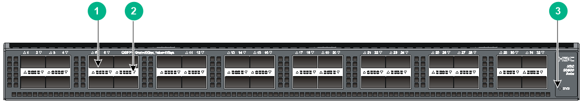
Figure2-1 Front panel
|
(1) QSFP+ port |
(2) QSFP+ port LED |
|
(3) System status LED (SYS) |
|
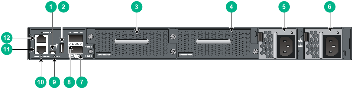
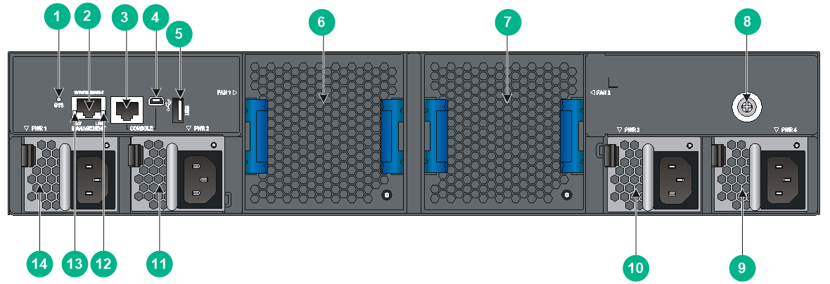
Figure2-2 Rear panel (LS-6800-32Q/LS-6800-32Q-H1)
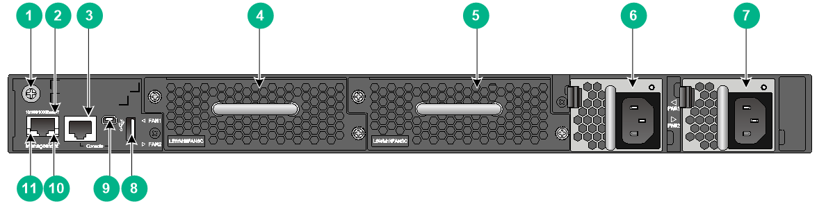
|
(1) Grounding screw (auxiliary grounding point 2) |
(2) Management Ethernet port |
|
(3) Serial console port |
(4) Fan tray 1 |
|
(5) Fan tray 2 |
(6) Power module 1 |
|
(7) Power module 2 |
(8) USB port |
|
(9) Mini USB console port |
(10) LINK LED for the management Ethernet port |
|
(11) ACT LED for the management Ethernet port |
|
The S6800-32Q switch comes with the two power module slots empty and a filler panel as an accessory. You can install one or two power modules for the switch as needed. In Figure2-2, two LSVM1AC650 power modules are installed in the power module slots.
The S6800-32Q switch comes with the two fan tray slots empty. You must install two fan trays of the same model for the switch. In Figure2-2, two LSWM1HFANSC fan trays are installed in the fan tray slots.
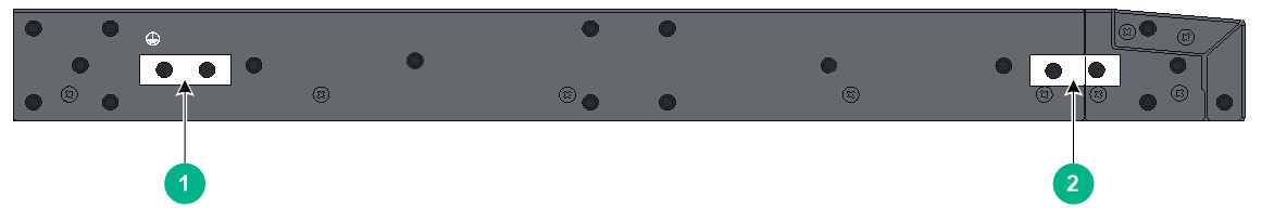
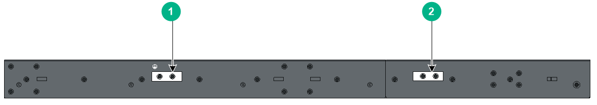
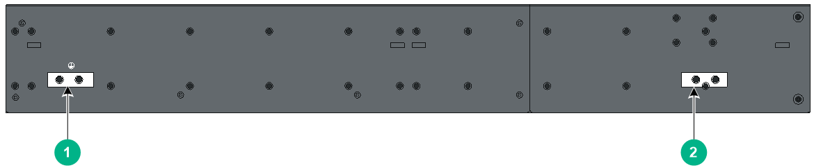
Figure2-3 Left side panel
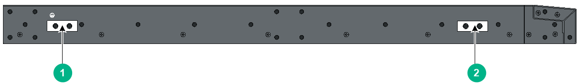
|
(1) Primary grounding point |
(2) Auxiliary grounding point 1 |
S6800-54QF
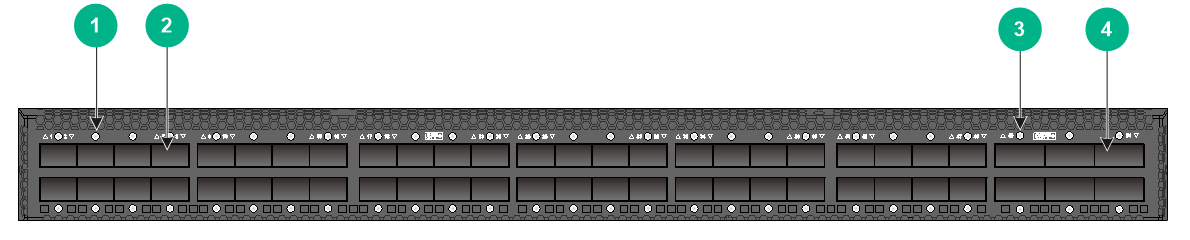
Figure2-4 Front panel (LS-6800-54QF/LS-6800-54QF-H1)
|
(1) SFP+ port LED |
(2) SFP+ port |
|
(3) QSFP+ port |
(4) QSFP+ port LED |
|
(5) System status LED (SYS) |
|
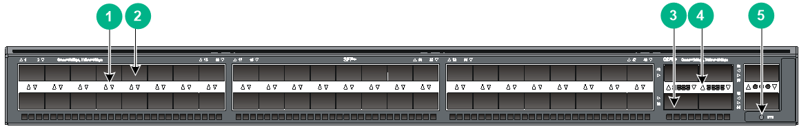
Figure2-5 Front panel (LS-6800-54QF-H3/LS-6800-54QF-H5)
|
(1) SFP+ port LED |
(2) SFP+ port |
|
(3) QSFP+ port LED |
(4) QSFP+ port |
Figure2-6 Rear panel (LS-6800-54QF/LS-6800-54QF-H1)
|
(1) Grounding screw (auxiliary grounding point 2) |
(2) Management Ethernet port |
|
(3) Console port |
(4) Fan tray 1 |
|
(5) Fan tray 2 |
(6) Power module 1 |
|
(7) Power module 2 |
(8) LINK LED for the management Ethernet port |
|
(9) ACT LED for the management Ethernet port |
(10) USB port |
Figure2-7 Rear panel (LS-6800-54QF-H3/LS-6800-54QF-H5)
|
(1) System status LED (SYS) |
(2) LINK/ACT LED for the copper management Ethernet port |
|
(3) LINK/ACT LED for the fiber management Ethernet port |
(4) Fan tray 1 |
|
(5) Fan tray 2 |
(6) Fan tray 3 |
|
(7) Power module 1 |
(8) Power module 2 |
|
(9) Fiber management Ethernet port (numbered 1) |
(10) Copper management Ethernet port (numbered 0) |
|
(11) Console port |
(12) Mini USB console port |
|
(13) USB port |
|
The LS-6800-54QF and LS-6800-54QF-H1 come with the two power module slots empty and a filler panel as an accessory. The LS-6800-54QF-H3 and LS-6800-54QF-H5 comes with power module slot 1 empty and a filler panel installed in power module slot 2. You can install one or two power modules for the switch as needed. In Figure2-6, two LSVM1AC300 power modules are installed in the power module slots. In Figure2-7, two PSR250-12A power modules are installed in the power module slots.
The LS-6800-54QF and LS-6800-54QF-H1 come with the two fan tray slots empty. The LS-6800-54QF-H3 and LS-6800-54QF-H5 comes with the three fan tray slots empty. You must install fan trays of the same model in all fan tray slots for the switch. In Figure2-6, two LSWM1HFANSC fan trays are installed in the fan tray slots. In Figure2-7, three LSPM1FANSA fan trays are installed in the fan tray slots.
Figure2-8 Left side panel (LS-6800-54QF and LS-6800-54QF-H1)
|
(1) Primary grounding point |
(2) Auxiliary grounding point 1 |
Figure2-9 Left side panel (LS-6800-54QF-H3/LS-6800-54QF-H5)
|
(1) Primary grounding point |
(2) Auxiliary grounding point 1 |
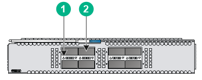
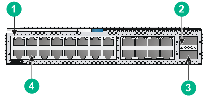
S6800-54QT
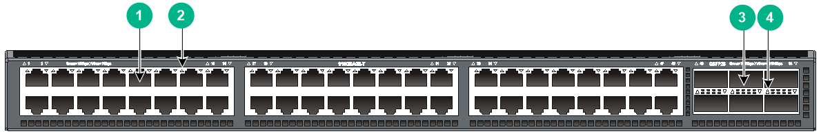
Figure2-10 Front panel (LS-6800-54QT/LS-6800-54QT-H1)
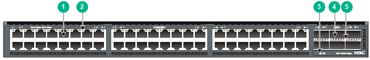
|
(1) 1/10GBASE-T autosensing Ethernet port |
(2) 1/10GBASE-T autosensing Ethernet port LED |
|
(3) System status LED (SYS) |
(4) QSFP+ port |
|
(5) QSFP+ port LED |
|
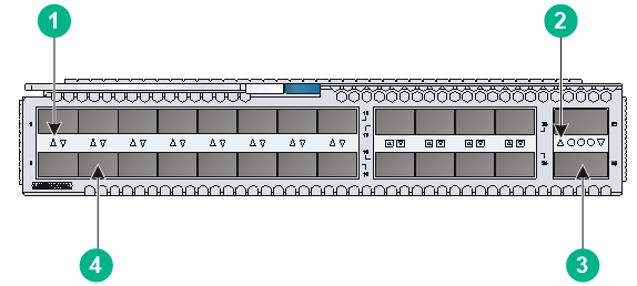
Figure2-11 Front panel (LS-6800-54QT-H3)
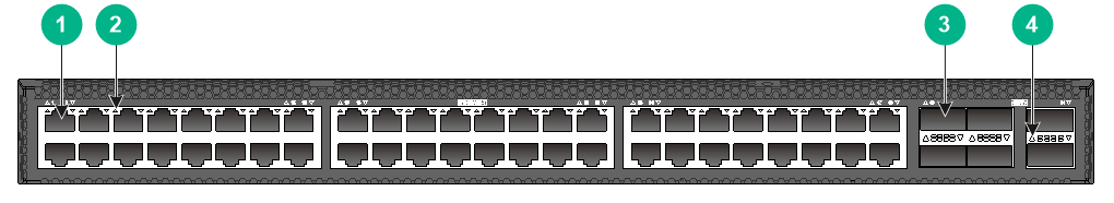
|
(1) 1/10GBASE-T autosensing Ethernet port |
(2) 1/10GBASE-T autosensing Ethernet port LED |
|
(3) QSFP+ port |
(4) QSFP+ port LED |
Figure2-12 Rear panel (LS-6800-54QT/LS-6800-54QT-H1)
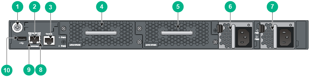
|
(1) Grounding screw (auxiliary grounding point 2) |
(2) Management Ethernet port |
|
(3) Console port |
(4) Fan tray 1 |
|
(5) Fan tray 2 |
(6) Power module 1 |
|
(7) Power module 2 |
(8) LINK LED for the management Ethernet port |
|
(9) ACT LED for the management Ethernet port |
(10) USB port |
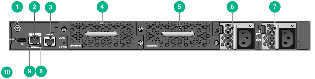
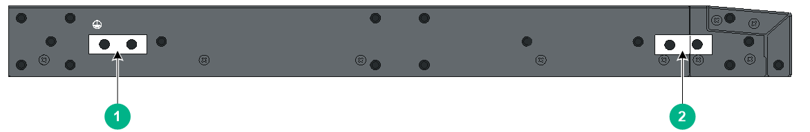
Figure2-13 Rear panel (LS-6800-54QT-H3)
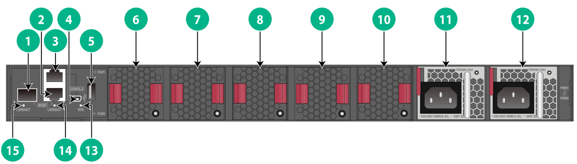
|
(1) Fiber management Ethernet port (numbered 1) |
(2) Copper management Ethernet port (numbered 0) |
|
(3) Console port |
(4) Mini USB console port |
|
(5) USB port |
(6) Fan tray 1 |
|
(7) Fan tray 2 |
(8) Fan tray 3 |
|
(9) Fan tray 4 |
(10) Fan tray 5 |
|
(11) Power module 1 |
(12) Power module 2 |
|
(13) System status LED (SYS) |
(14) LINK/ACT LED for the copper management Ethernet port |
|
(15) LINK/ACT LED for the fiber management Ethernet port |
|
The LS-6800-54QT and LS-6800-54QT-H1 come with the two power module slots empty and a filler panel as an accessory. The LS-6800-54QT-H3 comes with power module slot 1 empty and a filler panel installed in power module slot 2. You can install one or two power modules for the switch as needed. In Figure2-12, two LSVM1AC650 power modules are installed in the power module slots. In Figure2-13, two PSR450-12A1 power modules are installed in the power module slots.
The LS-6800-54QT and LS-6800-54QT-H1 come with the two fan tray slots empty. The LS-6800-54QT-H3 comes with the five fan tray slots empty. You must install fan trays of the same model in all fan tray slots for the switch. In Figure2-12, two LSWM1HFANSC fan trays are installed in the fan tray slots. In Figure2-13, five LSPM1FANSB fan trays are installed in the fan tray slots.
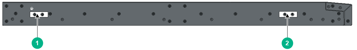
Figure2-14 Left side panel (LS-6800-54QT and LS-6800-54QT-H1)
|
(1) Primary grounding point |
(2) Auxiliary grounding point 1 |
Figure2-15 Left side panel (LS-6800-54QT-H3)
|
(1) Primary grounding point |
(2) Auxiliary grounding point 1 |
S6800-54HF
Figure2-16 Front panel
|
(1) SFP+ port |
(2) SFP+ port LED |
|
(3) QSFP28 port |
(4) QSFP28 port LED |
|
(1) Fiber management Ethernet port (numbered 1) |
(2) Console port |
|
(3) Mini USB console port |
(4) USB port |
|
(5) Fan tray 1 |
(6) Fan tray 2 |
|
(7) Power module 1 |
(8) Power module 2 |
|
(9) System status LED (SYS) |
(10) LINK/ACT LED for the copper management Ethernet port |
|
(11) Copper management Ethernet port (numbered 0) |
(12) LINK/ACT LED for the fiber management Ethernet port |
The S6800-54HF switch comes with the two power module slots empty and a filler panel as an accessory. You can install one or two power modules for the switch as needed. In Figure2-17, two LSVM1AC300 power modules are installed in the power module slots.
The S6800-54HF switch comes with the two fan tray slots empty. You must install two fan trays of the same model for the switch. In Figure2-17, two LSWM1HFANSC fan trays are installed in the fan tray slots.
|
(1) Primary grounding point |
(2) Auxiliary grounding point 1 |
S6800-54HT
Figure2-19 Front panel
|
(1) 1/10GBase-T autosensing Ethernet port |
(2) 1/10GBase-T autosensing Ethernet port LED |
|
(3) QSFP28 port |
(4) QSFP28 port LED |

|
(1) Fiber management Ethernet port (numbered 1) |
(2) Console port |
|
(3) Mini USB console port |
(4) USB port |
|
(5) Fan tray 1 |
(6) Fan tray slot 2 |
|
(7) Power module 1 |
(8) Power module 2 |
|
(9) System status LED (SYS) |
(10) LINK/ACT LED for the copper management Ethernet port |
|
(11) Copper management Ethernet port (numbered 0) |
(12) LINK/ACT LED for the fiber management Ethernet port |
The S6800-54HT switch comes with the two power module slots empty and a filler panel as an accessory. You can install one or two power modules for the switch as needed. In Figure2-20, two LSVM1AC650 power modules are installed in the power module slots.
The S6800-54HT switch comes with the two fan tray slots empty. You must install two fan trays of the same model for the switch. In Figure2-20, two LSWM1HFANSC fan trays are installed in the fan tray slots.
Figure2-21 Left side panel
|
(1) Primary grounding point |
(2) Auxiliary grounding point 1 |
S6800-2C
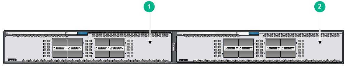
|
(1) Expansion module 1 |
(2) Expansion module 2 |
Figure2-23 Rear panel (LS-6800-2C/LS-6800-2C-H1)
|
(1) Mini USB console port |
(2) USB port |
|
(3) Fan tray 1 |
(4) Fan tray 2 |
|
(5) Power module 1 |
(6) Power module 2 |
|
(7) QSFP+ port |
(8) QSFP+ port LED |
|
(9) System status LED (SYS) |
(10) LINK/ACT LED for the management Ethernet port |
|
(11) Management Ethernet port |
(12) Serial console port |
The S6800-2C switch comes with expansion slot 1 empty and expansion slot 2 installed with a filler panel. You can install one or two expansion modules for the switch as needed. In Figure2-22, two LSWM18QC interface modules are installed in the expansion slots.
The S6800-2C switch comes with the two power module slots empty and a filler panel as an accessory. You can install one or two power modules for the switch as needed. In Figure2-23, two LSVM1AC650 power modules are installed in the power module slots.
The S6800-2C switch comes with the two fan tray slots empty. You must install two fan trays of the same model for the switch. In Figure2-23, two LSWM1HFANSC fan trays are installed in the fan tray slots.
Figure2-24 Left side panel
|
(1) Primary grounding point |
(2) Auxiliary grounding point 1 |
S6800-2C-FC
|
(1) Expansion module 1 |
(2) Expansion module 2 |

|
(1) Mini USB console port |
(2) USB port |
|
(3) Fan tray 1 |
(4) Fan tray 2 |
|
(5) Power module 1 |
(6) Power module 2 |
|
(7) QSFP+ port |
(8) QSFP+ port LED |
|
(9) System status LED (SYS) |
(10) LINK/ACT LED for the management Ethernet port |
|
(11) Management Ethernet port |
(12) Serial console port |
The S6800-2C-FC switch comes with expansion slot 1 empty and expansion slot 2 installed with a filler panel. You can install one or two expansion modules for the switch as needed. In Figure2-25, two LSWM18G24FC interface modules are installed in the expansion slots.
The S6800-2C-FC switch comes with the two power module slots empty and a filler panel as an accessory. You can install one or two power modules for the switch as needed. In Figure2-26, two LSVM1AC650 power modules are installed in the power module slots.
The S6800-2C-FC switch comes with the two fan tray slots empty. You must install two fan trays of the same model for the switch. In Figure2-26, two LSWM1HFANSC fan trays are installed in the fan tray slots.
Figure2-27 Left side panel

|
(1) Primary grounding point |
(2) Auxiliary grounding point 1 |
S6800-4C
|
(1) Expansion module 1 |
(2) Expansion module 2 |
|
(3) Expansion module 4 |
(4) Expansion module 3 |
Figure2-29 Rear panel (LS-6800-4C/LS-6800-4C-H1)
|
(1) System status LED (SYS) |
(2) Management Ethernet port |
|
(3) Serial console port |
(4) Mini USB console port |
|
(5) USB port |
(6) Fan tray 1 |
|
(7) Fan tray 2 |
(8) Grounding screw (auxiliary grounding point 2) |
|
(9) Power module 4 |
(10) Power module 3 |
|
(11) Power module 2 |
(12) LINK LED for the management Ethernet port |
|
(13) ACT LED for the management Ethernet port |
(14) Power module 1 |
The S6800-4C switch comes with a filler panel in all expansion slots except slot 1. You can install one to four expansion modules for the switch as needed. In Figure2-28, the LSWM18QC interface modules are installed in the expansion slots.
The S6800-4C switch comes with the four power module slot empty and two filler panels as accessories. You can install two to four power modules for the switch as needed. In Figure2-29, two LSVM1AC650 power modules are installed in the power module slots.
The S6800-4C switch comes with the two fan tray slots empty. You must install two fan trays of the same model for the switch. In Figure2-29, two LSWM1HFANSC fan trays are installed in the fan tray slots.
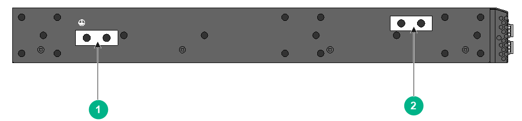
Figure2-30 Left side panel
|
(1) Primary grounding point |
(2) Auxiliary grounding point 1 |
3 FRUs and compatibility matrixes
|
|
CAUTION: · Select fan trays and power modules that have airflow directions that meet the ventilation requirements at the installation site. As a best practice, make sure the power modules and fan trays have the same airflow direction. · Do not install fan trays of different models on the same switch. · Do not install power modules of different models on the same switch. |
The switch supports hot swapping of power modules, fan trays, and expansion modules. The following tables describe the power modules, fan trays, and expansion modules available for the switch.
Table3-1 Compatibility matrix between the FRUs and S6800 switches (1)
|
FRUs |
Part No. |
S6800-32Q |
S6800-54HF |
S6800-54HT |
S6800-54QF (LS-6800-54QF) S6800-54QF (LS-6800-54QF-H1) |
S6800-54QT (LS-6800-54QT) S6800-54QT (LS-6800-54QT-H1) |
|
Power modules |
||||||
|
LSVM1AC650 |
0231A0QM |
Yes |
Yes |
Yes |
Yes |
Yes |
|
LSVM1DC650 |
0231A0QP |
Yes |
Yes |
Yes |
Yes |
Yes |
|
LSVM1AC300 |
0231A1SU |
No |
Yes |
No |
Yes |
No |
|
LSVM1DC300 |
0231A1SV |
No |
Yes |
No |
Yes |
No |
|
Fan trays |
||||||
|
LSWM1FANSC |
0231A0WE |
No |
Yes |
No |
Yes |
No |
|
LSWM1FANSCB |
0231A0WF |
No |
Yes |
No |
Yes |
No |
|
LSWM1HFANSC |
0231A1YT |
Yes |
Yes |
Yes |
Yes |
Yes |
|
LSWM1HFANSCB |
0231A1YS |
Yes |
Yes |
Yes |
Yes |
Yes |
Table3-2 Compatibility matrix between the FRUs and S6800 switches (2)
|
FRUs |
Part No. |
S6800-54QF (LS-6800-54QF-H3) S6800-54QF (LS-6800-54QF-H5) |
S6800-54QT (LS-6800-54QT-H3) |
|
Power modules |
|||
|
PSR250-12A |
0231A6M0 |
Yes |
No |
|
PSR250-12A1 |
0231A8FP |
Yes |
No |
|
PSR450-12A |
0231A6N9 |
Yes |
Yes |
|
PSR450-12A1 |
0231A6NC |
Yes |
Yes |
|
PSR450-12AHD |
0231A6NA |
Yes |
Yes |
|
PSR450-12D |
0231A6NB |
Yes |
Yes |
|
Fan trays |
|||
|
LSPM1FANSA |
0231A2VT |
LS-6800-54QF-H3: Yes LS-6800-54QF-H5: No |
Yes |
|
LSPM1FANSA-SN (support electronic label information reading) |
0231AG9E |
· LS-6800-54QF-H3: ¡ Yes, in versions later than Release 2702 ¡ Yes if the PCB is a B-version PCB produced in 2020 or later. To obtain the PCB version, contact H3C Support. · LS-6800-54QF-H5: Yes |
· Yes, in versions later than Release 2702 · Yes if the PCB is a B-version PCB produced in 2020 or later. To obtain the PCB version, contact H3C Support. |
|
LSPM1FANSB |
0231A2VU |
LS-6800-54QF-H3: Yes LS-6800-54QF-H5: No |
Yes |
|
LSPM1FANSB-SN (support electronic label information reading) |
0231AG9F |
· LS-6800-54QF-H3: ¡ Yes, in versions later than Release 2702 ¡ Yes if the PCB is a B-version PCB produced in 2020 or later. To obtain the PCB version, contact H3C Support. · LS-6800-54QF-H5: Yes |
· Yes, in versions later than Release 2702 · Yes if the PCB is a B-version PCB produced in 2020 or later. To obtain the PCB version, contact H3C Support. |
Table3-3 Compatibility matrix between the FRUs and S6800 switches (3)
|
FRUs |
Part No. |
S6800-2C |
S6800-2C-FC |
S6800-4C |
|
Power modules |
||||
|
LSVM1AC650 |
0231A0QM |
Yes |
Yes |
Yes |
|
LSVM1DC650 |
0231A0QP |
Yes |
Yes |
Yes |
|
Fan trays |
||||
|
LSWM1HFANSC |
0231A1YT |
Yes |
Yes |
No |
|
LSWM1HFANSCB |
0231A1YS |
Yes |
Yes |
No |
|
LSWM1BFANSC |
0231A2Y7 |
No |
No |
Yes |
|
LSWM1BFANSC-SN (support electronic label information reading) |
0231AG9G |
No |
No |
Yes, in Release 2702 and later |
|
LSWM1BFANSCB |
0231A2Y6 |
No |
No |
Yes |
|
LSWM1BFANSCB-SN (support electronic label information reading) |
0231AG9K |
No |
No |
Yes, in Release 2702 and later |
|
Expansion modules |
||||
|
LSWM116FC |
0231A5SB |
Yes, in Release 2702 and later |
No |
Yes, in Release 2702 and later |
|
0231A2U4 |
Yes, in Release 2509P02 and later |
No |
Yes, in Release 2509P02 and later |
|
|
LSWM18CQMSEC |
0231A8FM |
Yes, in Release 2612 and later |
No |
Yes, in Release 2612 and later |
|
LSWM124XGT2Q |
0231A2U6 |
Yes, in Release 2509P02 and later |
No |
Yes, in Release 2509P02 and later |
|
LSWM124XG2Q |
0231A2U5 |
Yes, in Release 2509P02 and later |
No |
Yes, in Release 2509P02 and later |
|
LSWM124XG2QL |
0231A2U7 |
Yes, in Release 2509P02 and later |
No |
Yes, in Release 2509P02 and later |
|
LSWM124XG2QFC |
0231A2YE |
Yes |
No |
Yes |
|
LSWM18G24FC |
0231A6B0 |
No |
Yes, in Release 2609 and later |
No |
|
LSWM12H2Q |
0231A4W7 |
Yes |
No |
Yes |
|
LSWM1FWD0 |
0231A4ES |
Yes |
No |
Yes |
|
LSWM1IPSD0 |
0231A5KC |
Yes |
No |
Yes |
|
LSWM1ADED0 |
0231A5KB |
Yes |
No |
Yes |
The S6800-32Q, S6800-54QF, S6800-54QT, S6800-54HF, S6800-54HT, S6800-2C, and S6800-2C-FC switches can operate correctly with only one power module. You can install two power modules on the switches for 1+1 redundancy.
The S6800-4C switches can operate correctly with two power modules. You can install four power modules on the switches for 2+2 redundancy.
|
|
IMPORTANT: · An S6800-54QT (LS-6800-54QT-H3) switch supports 4+1 fan tray redundancy. The switch can operate correctly with four fan trays. In the remaining fan tray slot, you can install a fan tray for 4+1 redundancy or a filler panel. On the other switch models, you must install a fan tray in each fan tray slot. · If an S6800-54QF (LS-6800-54QF and LS-6800-54QF-H1) or S6800-54HF switch uses 650 W power modules, install two LSWM1HFANSC, LSWM1HFANSCB, LSWM1FANSC, or LSWM1FANSCB fan trays to ensure heat dissipation. If the switch uses 300 W power modules, install two LSWM1FANSC or LSWM1FANSCB fan trays to ensure heat dissipation. |
4 Removable power modules
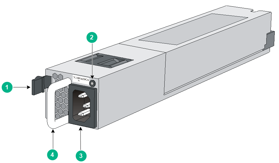
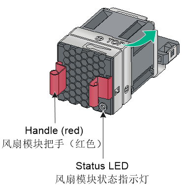
650W AC power module (LSVM1AC650)
View
Figure4-1 LSVM1AC650 power module
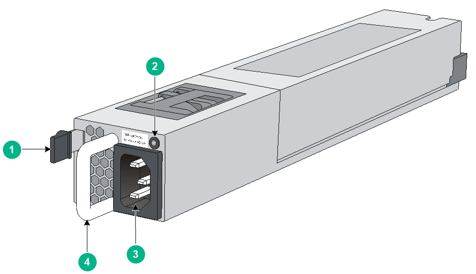
|
(1) Latch |
(2) Status LED |
|
(3) AC power receptacle |
(4) Handle |
For information about the power module status LED, see "Power module status LED."
Features
LSVM1AC650 is a power module with AC input and DC output. It can provide up to 650 W of output. Table4-1 describes the features provided by the LSVM1AC650 power module.
Table4-1 Features provided by the LSVM1AC650 power module
|
Feature |
Description |
|
Protection function |
Protection against input overcurrent, input undervoltage, output overvoltage, output shortcircuit, and overtemperature conditions. |
|
Support for redundancy |
Two power supplies can be connected in parallel to achieve 1+1 redundancy and load balancing. |
|
Support for hot swapping |
You can remove one of the power supplies in 1+1 redundancy when the switch is operating correctly. |
Technical specifications
Table4-2 Technical specifications
|
Item |
Specification |
|
Dimensions (H × W × D) |
40.2 × 50.5 × 326 mm (1.58 × 1.99 × 12.83 in), including the handle |
|
Weight |
1.04 kg (2.29 lb) |
|
Rated AC input voltage range |
100 VAC to 240 VAC @ 50 or 60 Hz |
|
Max AC input voltage range |
90 VAC to 264 VAC @ 47 to 63 Hz |
|
Rated HVDC input voltage range |
240 VDC |
|
Max HVDC input voltage range |
190 VDC to 290 VDC |
|
Rated input current |
10 A |
|
Rated output current |
53 A |
|
Rated output voltage |
12 V |
|
Rated output power |
650 W |
|
Melting current of power module fuse |
10 A/250 V |
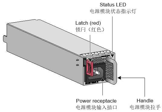
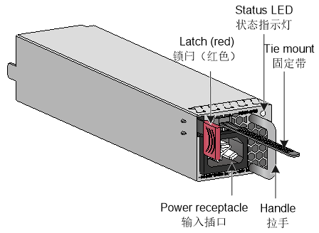
650W DC power module (LSVM1DC650)
View
Figure4-2 LSVM1DC650 power module
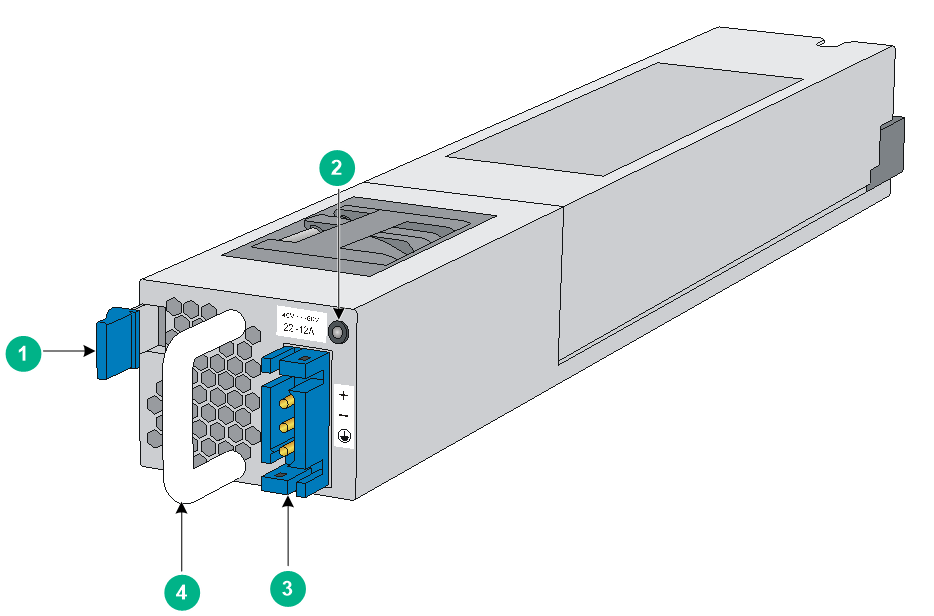
|
(1) Latch |
(2) Status LED |
|
(3) DC power receptacle |
(4) Handle |
For information about the power module status LED, see "Power module status LED."
Features
LSVM1DC650 is a power module with DC input and DC output. It can provide up to 650 W of output. Table4-3 describes the features provided by the LSVM1DC650 power module.
Table4-3 Features provided by the LSVM1DC650 power module
|
Feature |
Description |
|
Protection function |
Protection against input overcurrent, input undervoltage, output overvoltage, output shortcircuit, and overtemperature conditions. |
|
Support for redundancy |
Two power supplies can be connected in parallel to achieve 1+1 redundancy and load balancing. |
|
Support for hot swapping |
You can remove one of the power supplies in 1+1 redundancy when the switch is operating correctly. |
Technical specifications
Table4-4 Technical specifications
|
Item |
Specification |
|
Dimensions (H × W × D) |
40.2 × 50.5 × 326 mm (1.58 × 1.99 × 12.83 in), including the handle |
|
Weight |
1.07 kg (2.36 lb) |
|
Rated input voltage range |
–40 VDC to –60 VDC |
|
Max input voltage range |
–40 VDC to –72 VDC |
|
Rated input current |
25 A |
|
Rated output current |
53 A |
|
Rated output voltage |
12 V |
|
Rated output power |
650 W |
|
Melting current of power module fuse |
30 A/250 V |
300W AC power module (LSVM1AC300)
View
Figure4-3 LSVM1AC300 power module
|
(1) Latch |
(2) Status LED |
|
(3) AC power receptacle |
(4) Handle |
For information about the power module status LED, see "Power module status LED."
Features
LSVM1AC300 is a power module with AC input and DC output. It can provide up to 300 W of output. Table4-5 describes the features provided by the LSVM1AC300 power module.
Table4-5 Features provided by the LSVM1AC300 power module
|
Feature |
Description |
|
Protection function |
Protection against input overcurrent, input undervoltage, output overvoltage, output shortcircuit, and overtemperature conditions. |
|
Support for redundancy |
Two power supplies can be connected in parallel to achieve 1+1 redundancy and load balancing. |
|
Support for hot swapping |
You can remove one of the power supplies in 1+1 redundancy when the switch is operating correctly. |
Technical specifications
Table4-6 Technical specifications
|
Item |
Specification |
|
Dimensions (H × W × D) |
40.2 × 50.5 × 326 mm (1.58 × 1.99 × 12.83 in), including the handle |
|
Weight |
1.04 kg (2.29 lb) |
|
Rated AC input voltage range |
100 VAC to 240 VAC @ 50 or 60 Hz |
|
Max AC input voltage range |
90 VAC to 264 VAC @ 47 to 63 Hz |
|
Rated HVDC input voltage range |
240 VDC |
|
Max HVDC input voltage range |
190 VDC to 290 VDC |
|
Rated input current |
10 A |
|
Rated output current |
25 A (12 V)/3 A (5 V) |
|
Rated output voltage |
12 V |
|
Rated output power |
300 W |
|
Melting current of power module fuse |
6.3 A/250 V |
300W DC power module (LSVM1DC300)
View
Figure4-4 LSVM1DC300 power module

|
(1) Latch |
(2) Status LED |
|
(3) DC power receptacle |
(4) Handle |
For information about the power module status LED, see "Power module status LED."
Features
LSVM1DC300 is a power module with DC input and DC output. It can provide up to 300 W of output. Table4-7 describes the features provided by the LSVM1DC300 power module.
Table4-7 Features provided by the LSVM1DC300 power module
|
Feature |
Description |
|
Protection function |
Protection against input overcurrent, input undervoltage, output overvoltage, output shortcircuit, and overtemperature conditions. |
|
Support for redundancy |
Two power supplies can be connected in parallel to achieve 1+1 redundancy and load balancing. |
|
Support for hot swapping |
You can remove one of the power supplies in 1+1 redundancy when the switch is operating correctly. |
Technical specifications
Table4-8 Technical specifications
|
Item |
Specification |
|
Dimensions (H × W × D) |
40.2 × 50.5 × 326 mm (1.58 × 1.99 × 12.83 in), including the handle |
|
Weight |
1.2 kg (2.65 lb) |
|
Rated input voltage range |
–48 VDC to –60 VDC |
|
Max input voltage range |
–36 VDC to –72 VDC |
|
Rated input current |
8 A |
|
Rated output current |
25 A (12 V)/3 A (5 V) |
|
Rated output voltage |
12 V |
|
Rated output power |
300 W |
|
Melting current of power module fuse |
25 A/250 V |
250W AC power modules (PSR250-12A and PSR250-12A1)
View
Figure4-5 PSR250-12A power module
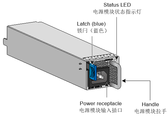
Figure4-6 PSR250-12A1 power module
For information about the power module status LED, see "Power module status LED."
Features
PSR250-12A and PSR250-12A1 are power modules with AC or HVDC input and DC output. They can provide up to 250 W of output. The PSR250-12A provides power module-side intake and port-side exhaust airflows, and the PSR250-12A1 provides port-side intake and power module-side exhaust airflows. Table4-9 describes the features provided by the PSR250-12A and PSR250-12A1 power modules.
Table4-9 Features provided by the PSR250-12A and PSR250-12A1 power modules
|
Feature |
Description |
|
Protection function |
Protection against input overcurrent, output current limiting, input undervoltage, output overvoltage, output shortcircuit, and overtemperature conditions. |
|
Support for redundancy |
Two power supplies can be connected in parallel to achieve 1+1 redundancy and load balancing. |
|
Support for hot swapping |
You can remove one of the power supplies in 1+1 redundancy when the switch is operating correctly. |
Technical specifications
Table4-10 Technical specifications
|
Item |
Specification |
|
Dimensions (H × W × D) |
40.2 × 50.5 × 236 mm (1.58 × 1.99 × 9.29 in), including the handle |
|
Weight |
1.04 kg (2.29 lb) |
|
Rated AC input voltage range |
100 VAC to 240 VAC @ 50 or 60 Hz |
|
Max AC input voltage range |
90 VAC to 290 VAC @ 47 to 63 Hz |
|
Rated HVDC input voltage range |
240 VDC |
|
Max HVDC input voltage range |
180 VDC to 320 VDC |
|
Rated AC input current |
4 A |
|
Rated output current |
20.9 A (12 V)/2 A (3.3 V) |
|
Rated HVDC input current |
2 A |
|
Rated output voltage |
12 V/3.3 V |
|
Rated output power |
250 W |
|
Melting current of power module fuse |
6.3 A/250 V |
450W AC power modules (PSR450-12A, PSR450-12A1, and PSR450-12AHD)
View
Figure4-7 PSR450-12A power module
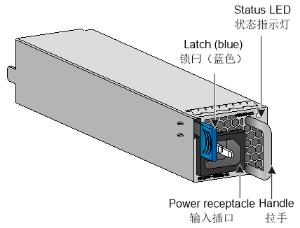
Figure4-8 PSR450-12A1 power module
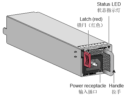
Figure4-9 PSR450-12AHD power module
For information about the power module status LED, see "Power module status LED."
Features
PSR450-12A, PSR450-12A1, and PSR450-12AHD are power modules with AC or HVDC input and DC output. The PSR450-12AHD supports 240 V or 336 V HVDC input. The PSR450-12A provides power module-side intake and port-side exhaust airflows. The PSR450-12A1 and PSR450-12AHD provide port-side intake and power module-side exhaust airflows. Table4-11 describes the features provided by the PSR450-12A, PSR450-12A1, and PSR450-12AHD power modules.
Table4-11 Features provided by the PSR450-12A, PSR450-12A1, and PSR450-12AHD power modules
|
Feature |
Description |
|
Protection function |
Protection against input overcurrent, output current limiting, input undervoltage, output overvoltage, output shortcircuit, and overtemperature conditions. |
|
Support for redundancy |
Two power supplies can be connected in parallel to achieve 1+1 redundancy and load balancing. |
|
Support for hot swapping |
You can remove one of the power supplies in 1+1 redundancy when the switch is operating correctly. |
Technical specifications
Table4-12 Technical specifications
|
Item |
PSR450-12A PSR450-12A1 |
PSR450-12AHD |
|
Dimensions (H × W × D) |
40.2 × 50.5 × 236 mm (1.58 × 1.99 × 9.29 in), including the handle |
40.2 × 50.5 × 236 mm (1.58 × 1.99 × 9.29 in), including the handle |
|
Weight |
1.04 kg (2.29 lb) |
1.04 kg (2.29 lb) |
|
Rated AC input voltage range |
100 VAC to 240 VAC @ 50 or 60 Hz |
100 VAC to 240 VAC @ 50 or 60 Hz |
|
Max AC input voltage range |
90 VAC to 290 VAC @ 47 to 63 Hz |
90 VAC to 290 VAC @ 47 to 63 Hz |
|
Rated HVDC input voltage range |
240 VDC |
240 VDC to 380 VDC |
|
Max HVDC input voltage range |
180 VDC to 320 VDC |
180 VDC to 400 VDC |
|
Rated AC input current |
6 A |
6 A |
|
Rated HVDC input current |
3.5 A |
3.5 A |
|
Rated output current |
37.5 A (12 V)/2 A (3.3 V) |
37.5 A (12 V)/2 A (3.3 V) |
|
Rated output voltage |
12 V/3.3 V |
12 V/3.3 V |
|
Rated output power |
450 W |
450 W |
|
Melting current of power module fuse |
· PSR450-12A: 10 A/310 VDC · PSR450-12A1: 10 A/250 VAC |
10 A/420 V |
450W DC power module (PSR450-12D)
View
Figure4-10 PSR450-12D power module
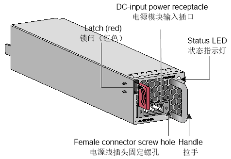
For information about the power module status LED, see "Power module status LED."
Features
PSR450-12D is a power module with DC input and DC output. It can provide up to 450 W of output. PSR450-12D provides port-side intake and power module-side exhaust airflows. Table4-13 describes the features provided by the PSR450-12D power module.
Table4-13 Features provided by the PSR450-12D power module
|
Feature |
Description |
|
Protection function |
Protection against input overcurrent, output current limiting, input undervoltage, output overvoltage, output shortcircuit, and overtemperature conditions. |
|
Support for redundancy |
Two power supplies can be connected in parallel to achieve 1+1 redundancy and load balancing. |
|
Support for hot swapping |
You can remove one of the power supplies in 1+1 redundancy when the switch is operating correctly. |
Technical specifications
Table4-14 Technical specifications
|
Item |
Specification |
|
Dimensions (H × W × D) |
40.2 × 50.5 × 326 mm (1.58 × 1.99 × 12.83 in), including the handle |
|
Weight |
1.07 kg (2.36 lb) |
|
Rated input voltage range |
–48 VDC to –60 VDC |
|
Max input voltage range |
–36 VDC to –72 VDC |
|
Rated input current |
· 12 A (48 VDC) · 10 A (60 VDC) |
|
Rated output current |
37.5 A (12 V)/2 A (3.3 V) |
|
Rated output voltage |
12 V/3.3 V |
|
Rated output power |
450 W |
|
Melting current of power module fuse |
20 A/125 V |
5 Removable fan trays
|
|
CAUTION: The switch has multiple fan tray slots. To ensure good ventilation of the switch, follow these restrictions and guidelines: · The switch comes with the fan tray slots empty. As a best practice to ensure adequate heat dissipation, install fan trays of the same model on the switch. Before powering on the switch, make sure the number of installed fan trays meets the minimum requirement. · Make sure all slots have a module or filler panel installed when the switch is operating. · If multiple fan trays fail on an operating switch, do not remove the fan trays at the same time. Replace the fan trays one after another and finish replacing each fan tray within 3 minutes. |
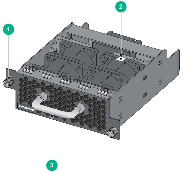
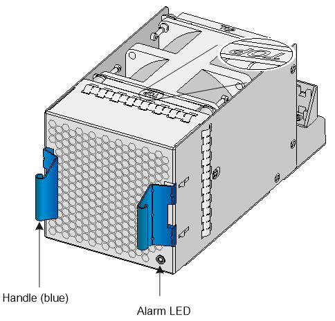
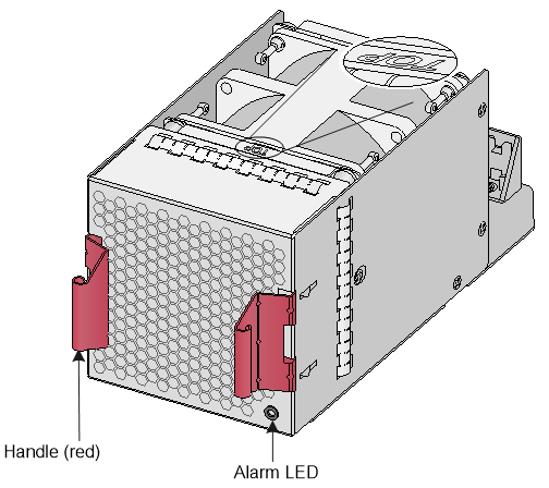
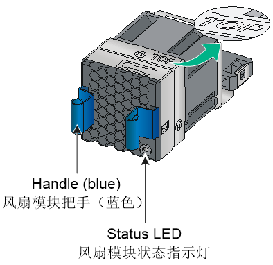
LSWM1FANSC/LSWM1FANSCB
View
Figure5-1 LSWM1FANSC/LSWM1FANSCB fan tray
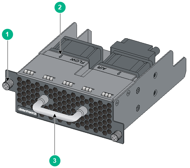
|
(1) Captive screw |
(2) Airflow direction label |
|
(3) Handle |
|
For information about the LED, see "Fan tray alarm LED."
Features
The LSWM1FANSC fan tray blows air from the power module side to the port side and the LSWM1FANSCB fan tray draws air from the port side to the power module side. The fan trays each comprise two separate fans and feature small size, fast heat dissipation, and hot swapping. They can automatically adjust the fan speed, providing powerful heat dissipation for the switch.
Technical specifications
Table5-1 Technical specifications
|
Item |
LSWM1FANSC |
LSWM1FANSCB |
|
Dimensions (H × W × D) |
80 × 80 × 232.6 mm (3.15 × 3.15 × 9.16 in), including the handle |
100 × 40.6 × 136.1 mm (3.94 × 1.60 × 5.36 in), including the handle |
|
Fan quantity |
2 |
2 |
|
Weight |
0.90 kg (1.98 lb) |
0.415 kg (0.91 lb) |
|
Airflow direction |
Air drawn in from the fan tray faceplate |
Air exhausted from the fan tray faceplate |
|
Fan speed |
18500 R.P.M |
18500 R.P.M |
|
Max airflow |
45 CFM (1.27 m3/min) |
45 CFM (1.27 m3/min) |
|
Input voltage |
12 V |
12 V |
|
Max power consumption |
19.5 W |
19.5 W |
LSWM1HFANSC/LSWM1HFANSCB
View
Figure5-2 LSWM1HFANSC/LSWM1HFANSCB fan tray
|
(1) Captive screw |
|
(2) Airflow direction label (The fans take air in from the direction indicated by the label.) |
|
(3) Handle |
For information about the LED, see "Fan tray alarm LED."
Features
The LSWM1HFANSC fan tray blows air from the power module side to the port side and the LSWM1HFANSCB fan tray draws air from the port side to the power module side. The fan trays each comprise two separate fans and feature small size, fast heat dissipation, and hot swapping. They can automatically adjust the fan speed, providing powerful heat dissipation for the switch.
Technical specifications
Table5-2 Technical specifications
|
Item |
LSWM1HFANSC |
LSWM1HFANSCB |
|
Dimensions (H × W × D) |
100 × 40.6 × 136.1 mm (3.94 × 1.60 × 5.36 in), including the handle |
100 × 40.6 × 136.1 mm (3.94 × 1.60 × 5.36 in), including the handle |
|
Fan quantity |
2 |
2 |
|
Weight |
0.475 kg (1.05 lb) |
0.475 kg (1.05 lb) |
|
Airflow direction |
Air drawn in from the fan tray faceplate |
Air exhausted from the fan tray faceplate |
|
Fan speed |
21000 R.P.M |
21000 R.P.M |
|
Max airflow |
70 CFM (1.98 m3/min) |
70 CFM (1.98 m3/min) |
|
Input voltage |
12 V |
12 V |
|
Max power consumption |
60 W |
60 W |
LSWM1BFANSC/LSWM1BFANSC-SN
View
Figure5-3 LSWM1BFANSC/LSWM1BFANSC-SN fan tray
For information about the LED, see "Fan tray alarm LED."
Features
The LSWM1BFANSC and LSWM1BFANSC-SN fan trays blow air from the power module side to the port side. The fan trays feature small size, fast heat dissipation, and hot swapping. They can automatically adjust the fan speed, providing powerful heat dissipation for the switch.
The LSWM1BFANSC-SN fan tray supports reading the electrical label information and the LSWM1BFANSC fan tray does not.
Technical specifications
Table5-3 Technical specifications
|
Item |
Specification |
|
Dimensions (H × W × D) |
300 × 167 × 125 mm (11.81 × 6.57 × 4.92 in), including the handle |
|
Fan quantity |
1 |
|
Weight |
0.90 kg (1.98 lb) |
|
Airflow direction |
Air drawn in from the fan tray faceplate |
|
Fan speed |
13300 R.P.M |
|
Max airflow |
120 CFM (3.40 m3/min) |
|
Input voltage |
12 V |
|
Max power consumption |
57 W |
LSWM1BFANSCB/LSWM1BFANSCB-SN
View
Figure5-4 LSWM1BFANSCB/LSWM1BFANSCB-SN fan tray
For information about the LED, see "Fan tray alarm LED."
Features
The LSWM1BFANSCB and LSWM1BFANSCB-SN fan trays draw air from the port side to the power module side. The fan trays feature small size, fast heat dissipation, and hot swapping. They can automatically adjust the fan speed, providing powerful heat dissipation for the switch.
The LSWM1BFANSCB-SN fan tray supports reading the electrical label information and the LSWM1BFANSCB fan tray does not.
Technical specifications
Table5-4 Technical specifications
|
Item |
Specification |
|
Dimensions (H × W × D) |
300 × 167 × 125 mm (11.81 × 6.57 × 4.92 in), including the handle |
|
Fan quantity |
1 |
|
Weight |
0.90 kg (1.98 lb) |
|
Airflow direction |
Air exhausted from the fan tray faceplate |
|
Fan speed |
13300 R.P.M |
|
Max airflow |
120 CFM (3.40 m3/min) |
|
Input voltage |
12 V |
|
Max power consumption |
57 W |
LSPM1FANSA/LSPM1FANSA-SN
View
Figure5-5 LSPM1FANSA/LSPM1FANSA-SN fan tray
For information about the LED, see "Fan tray alarm LED."
Features
The LSPM1FANSA and LSPM1FANSA-SN fan trays blow air from the power module side to the port side. The fan trays feature small size, fast heat dissipation, and hot swapping. They can automatically adjust the fan speed, providing powerful heat dissipation for the switch.
The LSPM1FANSA fan tray is available in black and silver models. The silver model supports reading the electrical label information and the black model does not.
The LSPM1FANSA-SN fan tray supports reading the electrical label information.
Technical specifications
Table5-5 Technical specifications
|
Item |
Specification |
|
Dimensions (H × W × D) |
160 × 66 × 60 mm (6.30 × 2.60 × 2.36 in), including the handle |
|
Fan quantity |
1 |
|
Weight |
0.12 kg (0.26 lb) |
|
Airflow direction |
Air drawn in from the fan tray faceplate |
|
Fan speed |
20000 R.P.M |
|
Max airflow |
20 CFM (0.57 m3/min) |
|
Input voltage |
12 V |
|
Max power consumption |
9.8 W |
LSPM1FANSB/LSPM1FANSB-SN
View
Figure5-6 LSPM1FANSB/LSPM1FANSB-SN fan tray
For information about the LED, see "Fan tray alarm LED."
Features
The LSPM1FANSB and LSPM1FANSB-SN fan trays draw air from the port side to the power module side. The fan trays feature small size, fast heat dissipation, and hot swapping. They can automatically adjust the fan speed, providing powerful heat dissipation for the switch.
The LSPM1FANSB fan tray is available in black and silver models. The silver model supports reading the electrical label information and the black model does not.
The LSPM1FANSB-SN fan tray supports reading the electrical label information.
Technical specifications
Table5-6 Technical specifications
|
Item |
Specification |
|
Dimensions (H × W × D) |
160 × 66 × 60 mm (6.30 × 2.60 × 2.36 in), including the handle |
|
Fan quantity |
1 |
|
Weight |
0.12 kg (0.26 lb) |
|
Airflow direction |
Air exhausted from the fan tray faceplate |
|
Fan speed |
20000 R.P.M |
|
Max airflow |
20 CFM (0.57 m3/min) |
|
Input voltage |
12 V |
|
Max power consumption |
9.8 W |
6 Expansion modules
The S6800-2C switch provides two expansion slots. The S6800-4C switch provides four expansion slots. Select expansion modules for the switch as required.
You can hot swap an expansion module when the switch is operating correctly, but do not hot swap an expansion module when the switch is starting up.
Table6-1 Interface modules available for the S6800-2C and S6800-4C switches
|
Interface module model |
Interface module name |
Port types and quantity |
|
LSWM18QC |
8-Port QSFP Plus Interface Module |
|
|
LSWM124XGT2Q |
24-Port 10GBASE-T and 2-Port QSFP Plus Interface Module with MACSec |
· 24 × 10-GE copper ports · 2 × QSFP+ ports |
|
LSWM124XG2Q |
24-Port SFP Plus and 2-Port QSFP Plus Interface Module with MACSec |
· 24 × SFP+ ports · 2 × QSFP+ ports |
|
LSWM124XG2QL |
24-Port SFP Plus and 2-Port QSFP Plus Interface Module |
|
|
LSWM124XG2QFC |
24 Ports SFP Plus and 2 Ports QSFP Plus Interface Module with FC |
|
|
LSWM12H2Q |
2-Port QSFP28 and 2-Port QSFP Plus Interface Module |
· 2 × QSFP28 ports · 2 × QSFP+ ports |
|
LSWM18CQMSEC |
8-Port QSFP28 Interface Module |
8 × QSFP28 ports |
|
LSWM116FC |
16-Port SFP28 Interface Module with FC |
16 × SFP28 ports |
The S6800-2C-FC switch provides two expansion slots. Select expansion modules for the switch as required.
Table6-2 Interface modules available for the S6800-2C-FC switch
|
Interface module model |
Interface module name |
Port types and quantity |
|
LSWM18G24FC |
24-Port SFP Plus and 2-Port QSFP Plus Interface Module with FC |
· 24 × SFP+ ports · 2 × QSFP+ ports |
|
|
IMPORTANT: · An LSWM12H2Q interface module can only be installed in expansion slots 1 and 2 on an S6800-2C (LS-6800-2C-H1) or S6800-4C (LS-6800-4C-H1) switch. On an S6800-4C (LS-6800-4C-H1) switch, both expansion slots 1 and 2 support hot swapping of LSWM12H2Q interface modules if one of them starts up with an LSWM12H2Q interface module installed. If both the slots start up empty, neither of them supports hot swapping of LSWM12H2Q interface modules. · You can install the LSWM12H2Q and non-LSWM12H2Q interface modules in the two expansion slots on the same S6800-2C (LS-6800-2C-H1) switch. If an expansion slot starts up with an LSWM12H2Q interface module installed, you can hot-swap only LSWM12H2Q interface modules in the slot. If an expansion slot starts up empty or with a non-LSWM12H2Q interface module installed, you can hot-swap only non-LSWM12H2Q interface modules in the slot. If you change the interface module type in a slot, you need to reboot the switch for the interface module to operate correctly. · You must install the same type of interface modules LSWM12H2Q or non-LSWM12H2Q in expansion slot 1 and slot 2 on the same S6800-4C (LS-6800-4C-H1) switch. If one or both of the expansion slots start up with an LSWM12H2Q interface module installed, you can hot-swap only LSWM12H2Q interface modules in the two slots. If both expansion slots start up empty, or one or both of the expansion slots start up with a non-LSWM12H2Q interface module installed, you can hot-swap only non-LSWM12H2Q interface modules in the two slots. |
Table6-3 Security modules available for the S6800-2C and S6800-4C switches
|
Security module |
Description |
Remarks |
|
LSWM1FWD0 |
The module is a fourth-generation high performance firewall module. It provides features including firewall, VPN, content filtering, content identification, URL filtering, and NAT. By using this module on a switch, you can enhance the switch security capabilities without changing the network topology. |
For more information, see H3C LSWM1FWD0 Module Manual. |
|
LSWM1IPSD0 |
The module is a fourth-generation high performance intrusion prevention system (IPS) module. The module provides an in-depth packet inspection engine based on signatures. By using this module, the switch can identify applications, prevent attacks that exploit the applications, and control user behaviors and application behaviors. |
For more information, see H3C LSWM1IPSD0 Module Manual. |
|
LSWM1ADED0 |
The module is a fourth-generation high performance application delivery engine (ADE) module. It provides powerful load-balancing and service optimization functions. You can deploy it on a switch at the aggregate or core layer of a data center to accelerate the response time and enhance service continuity of the data center. |
For more information, see H3C LSWM1ADED0 Module Manual. |
Table6-4 Interface module specifications
|
Model |
Dimensions (H × W × D) |
Weight |
Power consumption (static) |
Power consumption (fully configured) |
|
LSWM18QC |
40.1 × 214 × 274 mm (1.58 × 8.43 × 10.79 in) |
2 kg (4.41 lb) |
15 W |
30 W |
|
LSWM124XGT2Q |
40.1 × 214 × 274 mm (1.58 × 8.43 × 10.79 in) |
3 kg (6.61 lb) |
40 W |
123 W |
|
LSWM124XG2Q |
40.1 × 214 × 274 mm (1.58 × 8.43 × 10.79 in) |
2 kg (4.41 lb) |
40 W |
60 W |
|
LSWM124XG2QL |
40.1 × 214 × 274 mm (1.58 × 8.43 × 10.79 in) |
2 kg (4.41 lb) |
20 W |
36 W |
|
LSWM124XG2QFC |
40.1 × 214 × 274 mm (1.58 × 8.43 × 10.79 in) |
2 kg (4.41 lb) |
40 W |
60 W |
|
LSWM12H2Q |
40.1 × 214 × 274 mm (1.58 × 8.43 × 10.79 in) |
2 kg (4.41 lb) |
19 W |
79 W |
|
LSWM18CQMSEC |
40.1 × 214 × 274 mm (1.58 × 8.43 × 10.79 in) |
2 kg (4.41 lb) |
48 W |
93 W |
|
LSWM116FC |
40.1 × 214 × 274 mm (1.58 × 8.43 × 10.79 in) |
2 kg (4.41 lb) |
15 W |
60 W |
|
LSWM18G24FC |
40.1 × 214 × 274 mm (1.58 × 8.43 × 10.79 in) |
2 kg (4.41 lb) |
N/A |
N/A |
|
LSWM1FWD0 |
40.1 × 214 × 274 mm (1.58 × 8.43 × 10.79 in) |
2.1 kg (4.63 lb) |
N/A |
150 W |
|
LSWM1IPSD0 |
40.1 × 214 × 274 mm (1.58 × 8.43 × 10.79 in) |
2.1 kg (4.63 lb) |
N/A |
150 W |
|
LSWM1ADED0 |
40.1 × 214 × 274 mm (1.58 × 8.43 × 10.79 in) |
2.1 kg (4.63 lb) |
N/A |
150 W |
|
|
NOTE: Interface module dimensions are expressed in the Height (H) × Width (W) × Depth (D) format: · H—Height of the front panel of the expansion module. · W—Width of the front panel of the expansion module. · D—Depth from the front panel to the back of the expansion module. (The depth excludes the ejector levers.) |
LSWM18QC
The LSWM18QC interface module provides eight QSFP+ ports.
Figure6-1 LSWM18QC front panel
|
(1) QSFP+ port LED |
(2) QSFP+ port |
Ports and LEDs
For information about the ports and transceiver modules and cables available for the ports, see "QSFP+ port."
For information about the LEDs, see "QSFP+ port LED."
Technical specifications
Table6-5 Technical specifications
|
Item |
Specification |
|
Dimensions (H × W × D) |
40.1 × 214 × 274 mm (1.58 × 8.43 × 10.79 in), including the connector but excluding the ejector lever |
|
Weight |
2 kg (4.41 lb) |
|
Power consumption (static) |
15 W |
|
Power consumption (with typical configuration) |
22 W |
|
Power consumption (fully configured) |
30 W |
LSWM124XGT2Q
The LSWM124XGT2Q interface module provides twenty-four 10GBASE-T ports and two QSFP+ ports. All 10GBASE-T ports support MACsec.
Figure6-2 LSWM124XGT2Q front panel
|
(1) 10GBASE-T port LED |
(2) QSFP+ port LED |
|
(3) QSFP+ port |
(4) 10GBASE-T port |
Ports and LEDs
For information about the ports and transceiver modules and cables available for the ports, see "1/10GBASE-T autosensing Ethernet port" and "QSFP+ port."
For information about the LEDs, see "1/10GBASE-T autosensing Ethernet port LED" and "QSFP+ port LED."
Technical specifications
|
Item |
Specification |
|
Dimensions (H × W × D) |
40.1 × 214 × 274 mm (1.58 × 8.43 × 10.79 in), including the connector but excluding the ejector lever |
|
Weight |
3 kg (6.61 lb) |
|
Power consumption (static) |
40 W |
|
Power consumption (with typical configuration) |
81 W |
|
Power consumption (fully loaded) |
123 W |
LSWM124XG2Q
The LSWM124XG2Q interface module provides 24 SFP+ ports and 2 QSFP+ ports. All SFP+ ports support MACsec.
Figure6-3 LSWM124XG2Q front panel
|
(1) SFP+ port LED |
(2) QSFP+ port LED |
|
(3) QSFP+ port |
(4) SFP+ port |
Ports and LEDs
For information about the ports and transceiver modules and cables available for the ports, see "SFP+ port" and "QSFP+ port."
For information about the LEDs, see "SFP+ port LED" and "QSFP+ port LED."
Technical specifications
Table6-6 Technical specifications
|
Item |
Specification |
|
Dimensions (H × W × D) |
40.1 × 214 × 274 mm (1.58 × 8.43 × 10.79 in), including the connector but excluding the ejector lever |
|
Weight |
2 kg (4.41 lb) |
|
Power consumption (static) |
40 W |
|
Power consumption (with typical configuration) |
50 W |
|
Power consumption (fully loaded) |
60 W |
LSWM124XG2QL
The LSWM124XG2QL interface module provides 24 SFP+ ports and 2 QSFP+ ports.
Figure6-4 LSWM124XG2QL front panel
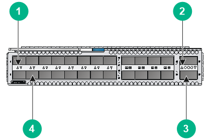
|
(1) SFP+ port LED |
(2) QSFP+ port LED |
|
(3) QSFP+ port |
(4) SFP+ port |
Ports and LEDs
For information about the ports and transceiver modules and cables available for the ports, see "SFP+ port" and "QSFP+ port."
For information about the LEDs, see "SFP+ port LED" and "QSFP+ port LED."
Technical specifications
Table6-7 Technical specifications
|
Item |
Specification |
|
Dimensions (H × W × D) |
40.1 × 214 × 274 mm (1.58 × 8.43 × 10.79 in), including the connector but excluding the ejector lever |
|
Weight |
2 kg (4.41 lb) |
|
Power consumption (static) |
20 W |
|
Power consumption (with typical configuration) |
28 W |
|
Power consumption (fully loaded) |
36 W |
LSWM124XG2QFC
The LSWM124XG2QFC interface module provides 24 SFP+ ports and 2 QSFP+ ports. The SFP+ ports can operate as Ethernet interfaces or FC interfaces.
Figure6-5 LSWM124XG2QFC front panel
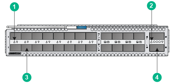
|
(1) SFP+ port LED |
(2) QSFP+ port LED |
|
(3) QSFP+ port |
(4) SFP+ port |
Ports and LEDs
For information about the ports and transceiver modules and cables available for the ports, see "SFP+ port," "FC interfaces," and "QSFP+ port."
For information about the LEDs, see "SFP+ port LED" and "QSFP+ port LED."
Technical specifications
Table6-8 Technical specifications
|
Item |
Specification |
|
Dimensions (H × W × D) |
40.1 × 214 × 274 mm (1.58 × 8.43 × 10.79 in), including the connector but excluding the ejector lever |
|
Weight |
2 kg (4.41 lb) |
|
Power consumption (static) |
40 W |
|
Power consumption (with typical configuration) |
50 W |
|
Power consumption (fully loaded) |
60 W |
LSWM12H2Q
The LSWM12H2Q interface module provides two QSFP28 ports and two QSFP+ ports.
Figure6-6 LSWM12H2Q front panel
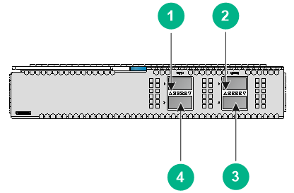
|
(1) QSFP+ port LED |
(2) QSFP28 port LED |
|
(3) QSFP28 port |
(4) QSFP+ port |
Ports and LEDs
For information about the ports and transceiver modules and cables available for the ports, see "QSFP+ port" and "QSFP28 port."
For information about the LEDs, see "QSFP28 port LED" and "QSFP+ port LED."
Technical specifications
Table6-9 Technical specifications
|
Item |
Specification |
|
Dimensions (H × W × D) |
40.1 × 214 × 274 mm (1.58 × 8.43 × 10.79 in), including the connector but excluding the ejector lever |
|
Weight |
2 kg (4.41 lb) |
|
Power consumption (static) |
19 W |
|
Power consumption (with typical configuration) |
N/A |
|
Power consumption (fully loaded) |
79 W |
LSWM18CQMSEC
The LSWM18CQMSEC interface module provides eight QSFP28 ports that all support MACsec.
Figure6-7 LSWM18CQMSEC front panel
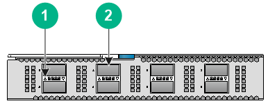
|
(1) QSFP28 port LED |
(2) QSFP28 port |
Ports and LEDs
For information about the ports and transceiver modules and cables available for the ports, see "QSFP28 port."
For information about the LEDs, see "QSFP28 port LED."
Technical specifications
Table6-10 Technical specifications
|
Item |
Specification |
|
Dimensions (H × W × D) |
40.1 × 214 × 274 mm (1.58 × 8.43 × 10.79 in), including the connector but excluding the ejector lever |
|
Weight |
2 kg (4.41 lb) |
|
Power consumption (static) |
48 W |
|
Power consumption (with typical configuration) |
70 W |
|
Power consumption (fully loaded) |
93 W |
LSWM116FC
The LSWM116FC interface module provides 16 SFP28 ports. The SFP28 ports can operate as Ethernet interfaces or FC interfaces. When they operate as FC interfaces, they support optical transceiver modules operating at different speeds and provide the FC service.
Figure6-8 LSWM116FC front panel
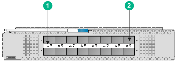
|
(1) SFP28 port LED |
(2) SFP28 port |
Ports and LEDs
For information about the ports and transceiver modules and cables available for the ports, see "FC interfaces."
For information about the LEDs, see "FC interface LEDs on the LSWM116FC, LSWM124XG2QFC, and LSWM18G24FC interface modules."
Technical specifications
Table6-11 Technical specifications
|
Item |
Specification |
|
Dimensions (H × W × D) |
40.1 × 214 × 274 mm (1.58 × 8.43 × 10.79 in), including the connector but excluding the ejector lever |
|
Weight |
2 kg (4.41 lb) |
|
Power consumption (static) |
15 W |
|
Power consumption (with typical configuration) |
37 W |
|
Power consumption (fully loaded) |
60 W |
LSWM18G24FC
The LSWM18G24FC interface module provides 24 SFP+ ports and 2 QSFP+ ports.
Figure6-9 LSWM18G24FC front panel
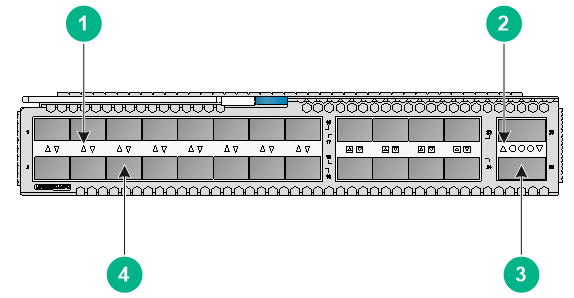
|
(1) SFP+ port LED |
(2) QSFP+ port LED |
|
(3) QSFP+ port |
(4) SFP+ port |
Ports and LEDs
For information about the ports and transceiver modules and cables available for the ports, see "QSFP+ port," "SFP+ port," and "FC interfaces."
For information about the LEDs, see "SFP+ port LED" and "QSFP+ port LED."
Technical specifications
Table6-12 Technical specifications
|
Item |
Specification |
|
Dimensions (H × W × D) |
40.1 × 214 × 274 mm (1.58 × 8.43 × 10.79 in), including the connector but excluding the ejector lever |
|
Weight |
2 kg (4.41 lb) |
|
Power consumption (static) |
N/A |
|
Power consumption (with typical configuration) |
N/A |
|
Power consumption (fully loaded) |
N/A |
LSWM1FWD0/LSWM1IPSD0/LSWM1ADED0
The LSWM1FWD0, LSWM1IPSD0, and LSWM1ADED0 interface modules each provide the following ports:
· One console port.
· One USB port.
· One RJ-45 management Ethernet port and one SFP management Ethernet port.
The views of LSWM1FWD0, LSWM1IPSD0, and LSWM1ADED0 are the same. This figure uses the LSWM1FWD0 as an example.
Figure6-10 LSWM1FWD0 front panel
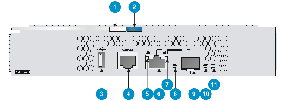
|
(1) Ejector lever |
(2) Latch |
|
(3) USB port (used for supplying power only) |
(4) Console port (CONSOLE) |
|
(5) RJ-45 management Ethernet port LED (LINK) |
(6) RJ-45 management Ethernet port |
|
(7) RJ-45 management Ethernet port LED (ACT) |
(8) SFP fiber management Ethernet port LED (LINK) |
|
(9) SFP fiber management Ethernet port |
(10) SFP fiber management Ethernet port LED (ACT) |
|
(11) System status LED (SYS) |
|
Ports and LEDs
For information about the ports and transceiver modules and cables available for the ports, see "Ports."
For information about the LEDs, see "LEDs."
Technical specifications
Table6-13 Technical specifications
|
Item |
Specification |
|
Dimensions (H × W × D) |
40.1 × 214 × 274 mm (1.58 × 8.43 × 10.79 in), including the connector but excluding the ejector lever |
|
Weight |
2.1 kg (4.63 lb) |
|
Power consumption (static) |
N/A |
|
Power consumption (with typical configuration) |
N/A |
|
Power consumption (fully loaded) |
N/A |
7 Ports and LEDs
|
|
IMPORTANT: · As a best practice, use H3C transceiver modules and cables for the switch. · The H3C transceiver modules and cables are subject to change over time. For the most up-to-date list of H3C transceiver modules and cables, contact H3C Support or marketing staff. · For more information about H3C transceiver modules and cables, see H3C Transceiver Modules User Guide. |
Ports
Console port
The S6800-54QF (LS-6800-54QF and LS-6800-54QF-H1) and S6800-54QT (LS-6800-54QT and LS-6800-54QT-H1) switches each have one console port.
Table7-1 Console port specifications (1)
|
Item |
Specification |
|
Connector type |
RJ-45 |
|
Compliant standard |
EIA/TIA-232 |
|
Operating mode |
Duplex Universal Asynchronous Receiver/Transmitter (Duplex UART) |
|
Transmission baud rate |
9600 bps (default) to 115200 bps |
|
Services |
· Provides connection to an ASCII terminal. · Provides connection to the serial port of a local or remote (through a pair of modems) PC running terminal emulation program. |
The other S6800 switches, including the S6800-54QF (LS-6800-54QF-H3), S6800-54QF (LS-6800-54QF-H5) and S6800-54QT (LS-6800-54QT-H3), each have two console ports: serial console port and Mini USB console port.
Table7-2 Console port specifications (2)
|
Item |
Console port |
Mini USB console port |
|
Connector type |
RJ-45 |
USB mini-Type B |
|
Compliant standard |
EIA/TIA-232 |
USB 2.0 |
|
Operating mode |
Duplex UART |
Mini USB interface UART |
|
Transmission baud rate |
9600 bps (default) to 115200 bps |
|
|
Services |
· Provides connection to an ASCII terminal. · Provides connection to the serial port of a local or remote (through a pair of modems) PC running terminal emulation program. |
· Provides connection to an ASCII terminal. · Provides connection to the USB port of a local PC running terminal emulation program. |
The serial console port and the mini USB console port cannot be connected simultaneously. If both ports are connected, only the mini USB console port takes effect.
Management Ethernet port
The S6800-32Q, S6800-54QF (LS-6800-54QF and LS-6800-54QF-H1), S6800-54QT (LS-6800-54QT and LS-6800-54QT-H1), S6800-2C, S6800-2C-FC, and S6800-4C switches each provide a copper management Ethernet port. The S6800-54QF (LS-6800-54QF-H3 and LS-6800-54QF-H5), S6800-54QT (LS-6800-54QT-H3), S6800-54HF, and S6800-54HT switches each provide a copper and a fiber management Ethernet port.
You can connect this port to a PC or management station for loading and debugging software or remote management.
Table7-3 Copper management Ethernet port specifications
|
Item |
Specification |
|
Connector type |
RJ-45 |
|
Connector quantity |
1 |
|
Compliant standard |
IEEE802.3ab |
|
Port transmission rate |
10/100/1000 Mbps, half/full duplex |
|
Transmission medium and max transmission distance |
100 m (328.08 ft) over category-5 twisted pair cable |
|
Functions and services |
Switch software and Boot ROM upgrade, network management |
Table7-4 Fiber management Ethernet port specifications
|
Item |
Specification |
|
Connector type |
LC |
|
Connector quantity |
1 |
|
Compliant standard |
IEEE802.3z |
|
Port transmission rate |
100/1000 Mbps, full duplex |
|
Available transceiver modules and cables |
FE SFP transceiver modules and GE SFP transceiver modules. For more information about the transceiver modules available for the fiber management Ethernet ports, see H3C S6800 & S6860 Switch Series Transceiver Module Compatibility Matrix. |
|
Functions and services |
Software upgrade and network management |
Table7-5 FE SFP transceiver modules
|
FE SFP transceiver module |
Central wavelength (nm) |
Connector |
Fiber type and diameter (µm) |
Max transmission distance |
|
SFP-FE-SX-MM1310-A |
1310 |
LC |
Multi-mode, 50/125 |
2 km (1.24 miles) |
|
Multi-mode, 62.5/125 |
||||
|
SFP-FE-LX-SM1310-A |
1310 |
LC |
Single-mode, 9/125 |
15 km (9.32 miles) |
Table7-6 GE SFP transceiver modules
|
GE SFP transceiver module |
Central wavelength (nm) |
Connector |
Fiber type and diameter (µm) |
Modal bandwidth (MHz*km) |
Max transmission distance |
|
SFP-GE-T SFP-GE-T-D |
N/A |
RJ-45 |
Twisted pair cable |
N/A |
100 m (328.08 ft) |
|
SFP-GE-SX-MM850-A SFP-GE-SX-MM850-D |
850 |
LC |
Multi-mode, 50/125 |
500 |
550 m (1804.46 ft) |
|
400 |
500 m (1640.42 ft) |
||||
|
Multi-mode, 62.5/125 |
200 |
275 m (902.23 ft) |
|||
|
160 |
200 m (656.17 ft) |
||||
|
SFP-GE-LX-SM1310-A |
1310 |
LC |
Single-mode, 9/125 |
N/A |
10 km (6.21 miles) |
|
Multi-mode, 50/125 |
500/400 |
550 m (1804.46 ft) |
|||
|
Multi-mode, 62.5/125 |
500 |
550 m (1804.46 ft) |
|||
|
SFP-GE-LX-SM1310-D |
1310 |
LC |
Single-mode, 9/125 |
N/A |
10 km (6.21 miles) |
USB port
The switch has one OHC-compliant USB2.0 port that can upload and download data at a rate up to 480 Mbps. You can use this USB port to access the file system on the Flash of the switch, for example, to upload or download application and configuration files.
|
|
NOTE: USB devices from different manufacturers vary in compatibilities and drivers. H3C does not guarantee the correct operation of all USB devices on the switch. If a USB device fails to operate on the switch, replace it with one from another manufacturer. |
QSFP28 port
Table7-7 QSFP28 port specifications
|
Item |
Specification |
|
Interface name |
40G/100G QSFP28 Ethernet optical interface |
|
Product compatibility |
· S6800-54HF switch: six QSFP28 ports on the front panel · S6800-54HT switch: six QSFP28 ports on the front panel · LSWM12H2Q interface module: two QSFP28 ports · LSWM18CQMSEC interface module: eight QSFP28 ports |
|
Connector type |
LC/MPO |
|
Description |
The 40G/100G QSFP28 Ethernet optical interfaces are mainly used for transmitting and receiving 40G/100G Ethernet optical interface services. |
|
Compliant standard |
IEEE802.3ba |
|
Optical interface attribute |
Depending on the installed transceiver modules or cables |
|
Operating mode |
Full duplex |
|
Available transceiver modules and cables |
· 100G QSFP28 transceiver modules · 100G QSFP28 copper cables · 100G QSFP28 fiber cables (AOC) · 100G QSFP28 to 4 × 25G SFP28 copper cables · 40G QSFP+ transceiver modules · 40G QSFP+ copper cables · 40G QSFP+ fiber cables (AOC) · 40G QSFP+ to 4 × 10G SFP+ copper cables NOTE: · For information about the transceiver modules and cables available for the QSFP28 ports, see H3C S6800 & S6860 Switch Series Transceiver Module Compatibility Matrix. · You can use a QSFP-40G-SR4-MM850 or QSFP-40G-CSR4-MM850 transceiver module to connect one 100G QSFP28 port to four 10G SFP+ ports. The QSFP+ transceiver module and SFP+ transceiver modules to be connected must be the same in specifications, including central wavelength and fiber type. · If you install an LSWM18CQMSEC interface module on the S6800-2C or S6800-4C switch, the QSFP28 ports on the interface module support only QSFP+ modules and cables. |
|
Support for splitting |
A QSFP28 port can be split into four 25G interfaces or four 10G interfaces, except in the following situations: · A QSFP28 port on the S6800-54HF or S6800-54HT switch can be split into four 10GE interfaces only in F2707 or a later version. To have the split configuration take effect, you must restart the switch. · The QSFP28 ports on the LSWM12H2Q interface module cannot be split into four interfaces. · If you install an LSWM18CQMSEC interface module on the S6800-4C switch, the two largest-numbered QSFP28 ports on the interface module cannot be split into four interfaces. |
QSFP+ port
Table7-8 QSFP+ port specifications
|
Item |
Specification |
|
Interface name |
40G QSFP+ Ethernet optical interface |
|
Product compatibility |
· LSWM18G24FC or LSWM12H2Q interface module: two QSFP+ ports · LSWM18QC interface modules: eight QSFP+ ports · LSWM124XG2Q, LSWM124XG2QFC, LSWM124XG2QL, or LSWM124XGT2Q interface module: two QSFP+ ports · S6800-32Q switch: 32 QSFP+ ports on the front panel · S6800-54QF, S6800-54QT, or S6800-54QF switch: six QSFP+ ports on the front panel · S6800-2C or S6800-2C-FC switch: two QSFP+ ports on the front panel |
|
Connector |
LC/MPO |
|
Description |
The 40G QSFP+ Ethernet optical interfaces are mainly used for transmitting and receiving 40GE optical interface services. |
|
Compliant standard |
IEEE802.3ba |
|
Optical interface attribute |
Depending on the installed transceiver modules or cables |
|
Operating mode |
Full duplex |
|
Available transceiver modules and cables |
· 40G QSFP+ transceiver modules · 40G QSFP+ copper cables · 40G QSFP+ fiber cables (AOC) · 40G QSFP+ to 4 × 10G SFP+ copper cables NOTE: · For information about the transceiver modules and cables available for the QSFP+ ports, see H3C S6800 & S6860 Switch Series Transceiver Module Compatibility Matrix. · You can use a QSFP-40G-SR4-MM850 or QSFP-40G-CSR4-MM850 transceiver module to connect one 40G QSFP+ port to four 10G SFP+ ports. The QSFP+ transceiver module and SFP+ transceiver modules to be connected must be the same in specifications, including central wavelength and fiber type. |
|
Support for splitting |
A QSFP+ port can be split into four 10G interfaces, except in the following situations: · The eight 40GE interfaces numbered FortyGigE 1/0/1 to FortyGigE 1/0/4 and FortyGigE 1/0/29 to FortyGigE 1/0/32 on the S6800-32Q switch cannot be split. · If you install an LSWM124XGT2Q, LSWM124XG2Q, LSWM124XG2QL, or LSWM124XG2QFC interface module on the S6800-4C switch, the QSFP+ ports on the interface module cannot be split. · If you install an LSWM18QC interface module on the S6800-4C switch, the two largest-numbered QSFP+ ports on the interface module cannot be split. |
SFP+ port
Table7-9 SFP+ port specifications
|
Item |
Specification |
|
Interface name |
10G SFP+ Ethernet optical interface |
|
Product compatibility |
· LSWM124XG2Q, LSWM124XG2QFC, LSWM124XG2QL, or LSWM18G24FC interface module: 24 SFP+ ports · S6800-54Q or S6800-54HF switch: 48 SFP+ ports |
|
Connector |
LC |
|
Description |
The 10G SFP+ Ethernet optical interfaces are mainly used for transmitting and receiving GE or 10GE optical interface services. |
|
Compliant standard |
IEEE802.3ae |
|
Optical interface attribute |
Depending on the installed transceiver modules or cables |
|
Operating mode |
· The SFP+ ports on the LSWM124XG2Q and LSWM124XG2QFC interface modules support 1000 Mbps and 10 Gbps autosensing and full-duplex mode. · The SFP+ ports installed with GE SFP+ transceiver modules on the LSWM124XG2QL interface module do not support rate or duplex mode autonegotiation. You must execute the speed 1000 and duplex full commands on the ports at both ends. · To use a GE SFP transceiver module except for an SFP-GE-T or SFP-GE-T-D transceiver module, make sure the autonegotiation feature is disabled on the peer port. |
|
Available transceiver modules and cables |
· 10G SFP+ transceiver modules · 10G SFP+ copper cables · 10G SFP+ fiber cables (AOC) · 1G SFP transceiver modules NOTE: For information about the transceiver modules and cables available for the SFP+ ports, see H3C S6800 & S6860 Switch Series Transceiver Module Compatibility Matrix. |
|
Restrictions and guidelines |
· Installed with an SFP-GE-T or SFP-GE-T-D transceiver module, an SFP+ port can operate only at 1 Gbps. · If the switch connects to the peer device through an SFP-GE-T or SFP-GE-T-D transceiver module, packet loss occurs when the switch restarts, because the peer interface comes up before the local interface can come up. As a best practice, configure dynamic link aggregation to avoid such an issue if the switch is connected to the peer device through an aggregate link. |
FC interfaces
A port on an LSWM116FC interface module can operate as an Ethernet interface or FC interface. When it operates as an FC interface, it supports 8G/16G/32G FC modules. When it operates as an Ethernet interface, it supports only GE SFP transceiver modules, 10GE SFP+ transceiver modules, or 10GE SFP+ cables. For the transceiver modules and cables available for the FC interfaces, see H3C S6800 & S6860 Switch Series Transceiver Module Compatibility Matrix.
The ports on an LSWM116FC interface module operate in 32G FC mode by default. To split a 32-Gbps FC interface into two 16-Gbps FC breakout interfaces or combine two 16-Gbps FC breakout interfaces back into a 32-Gbps FC interface, execute the using sixteengigfc or using thirty-twogigfc command in interface view. For more information, see FC and FCoE configuration in H3C S6800[S6860][S6861] (R27xx) & S6820 (R630x) Switch Series Configuration Guide.
For an S6800-4C switch installed with an LSWM116FC interface module, Ethernet interfaces 13 to 16 on the interface module are unavailable and FC interfaces 14 and 16 cannot be split into two 16-Gbps FC breakout interfaces.
The 24 SFP+ ports on an LSWM124XG2QFC or LSWM18G24FC can operate as Ethernet interfaces or FC interfaces. When such an SFP+ port operates as an FC interface, it supports 8G FC modules SFP-FC-8G-SW-MM850 and SFP-FC-8G-LW-SM1310.
To change the port type between a Layer 2 Ethernet interface and an FC interface, execute the port-type command in Layer 2 Ethernet interface view. For more information, see FC and FCoE configuration in H3C S6800[S6860][S6861] (R27xx) & S6820 (R630x) Switch Series Configuration Guide.
1/10GBASE-T autosensing Ethernet port
Table7-10 1/10GBASE-T autosensing Ethernet port specifications
|
Item |
Specification |
|
Interface name |
10GBASE-T Ethernet interface |
|
Product compatibility |
· S6800-54QT or S6800-54HT switch: forty-eight 10GBASE-T ports · LSWM124XGT2Q interface module: twenty-four 10GBASE-T ports |
|
Connector |
RJ-45 |
|
Description |
The 10GBASE-T Ethernet interfaces are mainly used for transmitting and receiving GE/10GE copper interface services. |
|
Compliant standard |
IEEE802.3an, IEEE802.3az |
|
Interface attribute and operating mode |
· 1 Gbps, full duplex · 10 Gbps, full duplex · MDI/MDI-X autosensing |
|
Max transmission distance |
· Category-6 UTP cable: 55 m (180.45 ft) · Category-6 STP cable: 100 m (328.08 ft) · Category-6A or above twisted pair cables: 100 m (328.08 ft) |
|
Cables |
Category-6 or above twisted pair cables. Both straight-through cables and crossover cables are available. |
LEDs
System status LED
The switch provides a system status LED to indicate the operating status of the switch.
Table7-11 Description for the system status LED on the switch
|
LED mark |
Status |
Description |
|
SYS |
Steady green |
The switch is operating correctly. |
|
Flashing green |
The switch is performing power-on self test (POST). |
|
|
Steady red |
The system has failed to pass POST or has problems such as fan failure. |
|
|
Flashing red |
Some ports have failed to pass POST. |
|
|
Off |
The switch is powered off or has failed to start up. |
The LSWM1FWD0, LSWM1IPSD0, and LSWM1ADED0 interface modules each provide a system status LED to indicate the operating status of the interface module.
Table7-12 Description for the system status LED on an interface module
|
LED mark |
Status |
Description |
|
SYS |
Slow flashing green (1 Hz) |
The system has started up and is operating correctly. |
|
Fast flashing green (8 Hz) |
The system is loading software. |
|
|
Off |
The interface module has no power input or is faulty. |
SFP+ port LED
Table7-13 SFP+ port LED description
|
LED status |
Description |
|
Steady green |
A transceiver module or cable has been correctly installed. The port has a link and is operating at 10 Gbps. |
|
Flashing green |
The port is sending or receiving data at 10 Gbps. |
|
Steady yellow |
A transceiver module or cable has been correctly installed. The port has a link and is operating at 1 Gbps. |
|
Flashing yellow |
The port is sending or receiving data at 1 Gbps. |
|
Off |
No transceiver module or cable has been installed or no link is present on the port. |
QSFP+ port LED
Table7-14 QSFP+ port LED description
|
LED status |
Description |
|
Steady green |
A transceiver module or cable has been correctly installed. The port has a link and is operating at 40 Gbps. |
|
Flashing green |
The port is sending or receiving data at 40 Gbps. |
|
Steady yellow |
A transceiver module or cable has been correctly installed. The port has a link and is operating at 10 Gbps. |
|
Flashing yellow |
The port is sending or receiving data at 10 Gbps. |
|
Off |
No transceiver module or cable has been installed or no link is present on the port. |
QSFP28 port LED
Table7-15 QSFP28 port LED description
|
LED status |
Description |
|
Steady green |
A transceiver module or cable has been correctly installed. The port has a link and is operating at 100 Gbps. |
|
Flashing green |
The port is sending or receiving data at 100 Gbps. |
|
Steady yellow |
A transceiver module or cable has been correctly installed. The port has a link and is operating at 10/40 Gbps. |
|
Flashing yellow (3 Hz) |
The port is sending or receiving data at 10/40 Gbps. |
|
Off |
No transceiver module or cable has been installed or no link is present on the port. |
Management Ethernet port LED
The S6800-32Q, S6800-54QF (LS-6800-54QF and LS-6800-54QF-H1), S6800-54QT (LS-6800-54QT and LS-6800-54QT-H1), and S6800-4C switches each provide one LINK LED and one ACT LED for the management Ethernet port.
The LSWM1FWD0, LSWM1IPSD0, and LSWM1ADED0 interface modules each provide one LINK LED and one ACT LED for the management Ethernet port.
Table7-16 Copper management Ethernet port LED description (1)
|
LED mark |
Status |
Description |
|
LINK |
Off |
No link is present. |
|
Steady green |
The port is operating at 10/100/1000 Mbps. |
|
|
ACT |
Off |
The port is not receiving or sending data. |
|
Flashing yellow |
The port is sending or receiving data. |
The S6800-2C and S6800-2C-FC switches each provide a LINK/ACT LED for each management Ethernet port. See Table7-17.
Table7-17 Copper management Ethernet port LED description (2)
|
LED mark |
Status |
Description |
|
LINK/ACT |
Steady green |
The port is operating at 10/100/1000 Mbps and a link is present. |
|
Flashing green |
The port is receiving or sending data. |
|
|
Off |
No link is present. |
The S6800-54QF (LS-6800-54QF-H3 and LS-6800-54QF-H5), S6800-54QT (LS-6800-54QT-H3), S6800-54HF, and S6800-54HT switches each provide a LINK/ACT LED for each management Ethernet port. For LED description for the copper management Ethernet port, see Table7-17. For LED description for the fiber management Ethernet port, see Table7-18.
Table7-18 Fiber management Ethernet port LED description
|
LED mark |
Status |
Description |
|
LINK/ACT |
Off |
No link is present. |
|
Steady green |
The port is operating at 100/1000 Mbps and a link is present. |
|
|
Flashing green |
The port is receiving or sending data. |
1/10GBASE-T autosensing Ethernet port LED
Table7-19 1/10GBASE-T autosensing Ethernet port LED description
|
LED status |
Description |
|
Steady green |
The port has a link and is operating at 10 Gbps. |
|
Flashing green |
The port is sending or receiving data at 10 Gbps. |
|
Steady yellow |
The port has a link and is operating at 1 Gbps. |
|
Flashing yellow |
The port is sending or receiving data at 1 Gbps. |
|
Off |
No link is present on the port. |
Power module status LED
The power modules each provide a power module status LED on the panel to show the power input status and power output status.
Table7-20 Power module status LED description
|
LED status |
Description |
|
Steady green |
The power module is operating correctly in active mode. |
|
Flashing green |
The power module is operating correctly in standby mode. |
|
Steady red |
The power module is faulty or enters protection state. |
|
Alternating between red and green |
An alarm occurs on the power module when one of the following conditions exists on the power module but the power module does not enter protection state: · Output overvoltage. · Output undervoltage. · Output overcurrent. · Output power overload. · Overtemperature. |
|
Flashing red |
The current power module has no current input. If the switch has two power modules installed and one module has current input and the other does not, the LED for the module without current input will flash red. |
|
Off |
The power module has no current input. |
FC interface LEDs on the LSWM116FC, LSWM124XG2QFC, and LSWM18G24FC interface modules
The LSWM116FC and LSWM124XG2QFC interface modules can be installed only on S6800-2C and S6800-4C switches. The LSWM18G24FC interface module can be installed only on an S6800-2C-FC switch. These interface modules support FC and provide a LED for each interface to indicate the interface status.
· For an LSWM116FC interface module installed on an S6800-2C or S6800-4C switch, all its interfaces are 32G FC interfaces by default. See Table7-21 for the FC interface LED description. The 32G FC interfaces can be changed to Ethernet interfaces.
· For an LSWM124XG2QFC interface module installed on an S6800-2C or S6800-4C switch, all its interfaces are Ethernet interfaces by default. You can change the Ethernet interfaces to 8G FC interfaces. For the 8G FC interface LED description, see Table7-21.
· For an LSWM18G24FC interface module installed on an S6800-2C-FC switch, all its interfaces are Ethernet interfaces by default. You can change the Ethernet interfaces to 8G FC interfaces. For the 8G FC interface LED description, see Table7-21.
Table7-21 FC interface LED description
|
LED status |
Description |
|
Steady green |
The FC interface has a link and is operating at the maximum speed. |
|
Flashing green |
The FC interface is sending or receiving data at the maximum speed. |
|
Steady yellow |
The FC interface has a link and is operating at a speed lower than the maximum speed. |
|
Flashing yellow |
The FC interface is sending or receiving data at a speed lower than the maximum speed. |
|
Off |
No link is present on the interface. |
Fan tray alarm LED
The LSWM1BFANSC/LSWM1BFANSC-SN, LSWM1BFANSCB/LSWM1BFANSCB-SN, LSPM1FANSA/LSPM1FANSA-SN, and LSPM1FANSB/LSPM1FANSB-SN fan trays each provide an alarm LED.
Table7-22 Fan tray alarm LED description
|
LED status |
Description |
|
On |
The fan tray is faulty. |
|
Off |
The fan tray is operating correctly. |
8 Cooling system
|
|
CAUTION: To guarantee heat dissipation, you must install fan trays of the same model for the switch. |
To dissipate heat timely and ensure system stability, the switch uses the front-rear air aisle cooling system. Consider the site ventilation design when you plan the installation site for the switch.
Table8-1 Cooling system for the switch
|
Switch model |
Available fan trays |
Airflow direction |
|
· S6800-32Q · S6800-2C · S6800-2C-FC · S6800-54QT (LS-6800-54QT and LS-6800-54QT-H1) · S6800-54HT |
LSWM1HFANSC |
From the power module side to the port side |
|
LSWM1HFANSCB |
From the port side to the power module side |
|
|
S6800-4C |
LSWM1BFANSC or LSWM1BFANSC-SN |
From the power module side to the port side |
|
LSWM1BFANSCB or LSWM1BFANSCB-SN |
From the port side to the power module side |
|
|
· S6800-54QF (LS-6800-54QF and LS-6800-54QF-H1) · S6800-54HF |
LSWM1FANSC or LSWM1HFANSC |
From the power module side to the port side |
|
LSWM1FANSCB or LSWM1HFANSCB |
From the port side to the power module side |
|
|
· S6800-54QF (LS-6800-54QF-H3) · S6800-54QF (LS-6800-54QF-H5) · S6800-54QT (LS-6800-54QT-H3) |
LSPM1FANSA or LSPM1FANSA-SN |
From the power module side to the port side |
|
LSPM1FANSB or LSPM1FANSB-SN |
From the port side to the power module side |
Figure8-1 Airflow from the power module side to the port side through the S6800-32Q chassis (with LSWM1HFANSC fan trays)
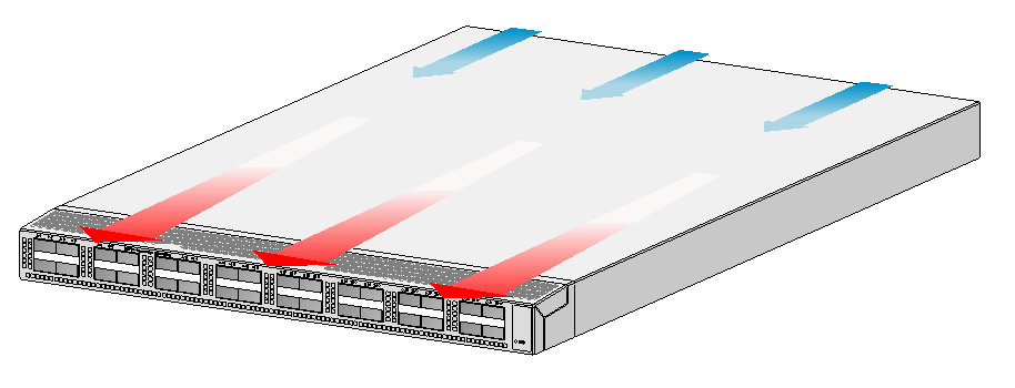
Figure8-2 Airflow from the port side to the power module side through the S6800-32Q chassis (with LSWM1HFANSCB fan trays)