- Released At: 02-06-2022
- Page Views:
- Downloads:
- Table of Contents
- Related Documents
-
H3C LSXM1SUPRS2 supervisor engine unit
1 Identifier
The card identifier LSXM1SUPRS2 is in the upper right corner of the front panel.
2 Specifications
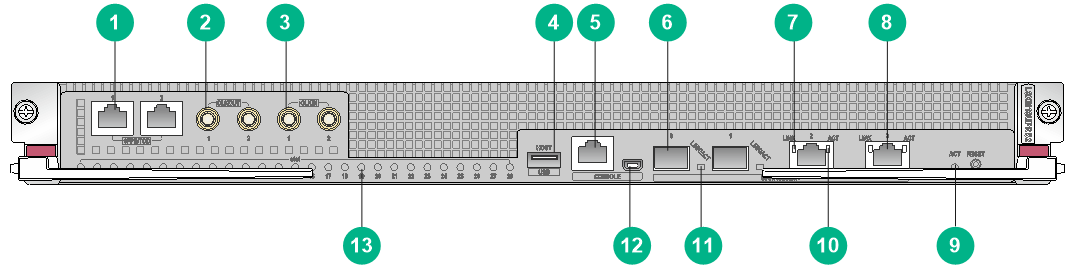
Figure 1 Front panel
|
(1) 1PPS/ToD time synchronization port |
(2) SMB clock output port |
|
(3) SMB clock input port |
(4) USB port |
|
(5) Console port (CONSOLE) |
(6) GE SFP port for management and upgrade |
|
(7) 10/100/1000BASE-T port LED (LINK) |
|
|
(8) 10/100/1000BASE-T port for management and upgrade |
|
|
(9) Active/standby status LED |
(10) 10/100/1000BASE-T port LED (ACT) |
|
(11) GE SFP port LED |
(12) Mini USB console port |
|
(13) Slot status LED |
|
Table 1 Module specifications
|
Item |
Specification |
|
Processor |
Quad Core @ 2.2 GHz |
|
Memory |
32 GB |
|
Flash |
4 GB |
|
NVRAM |
512 KB |
|
SSD |
240 GB |
|
Power consumption |
50 W to 60 W |
|
LED |
· 28 × slot status LEDs · 2 × 10/100/1000BASE-T management and upgrade port LEDs · 2 × GE SFP management and upgrade port LEDs · 1 × active/standby status LED For more information about the LEDs, see Table 2 and Table 3. |
|
Connector |
· RJ-45 · LC · USB (Type A) · Mini-USB (Type AB) |
|
Port |
· 1 × RJ-45 console port · 1 × mini-USB console port · 2 × 10/100/1000BASE-T ports for management and upgrade · 2 × GE SFP ports for management and upgrade · 1 × USB port (USB 3.0, Host port) · 2 × 1PPS/ToD time synchronization ports · 2 × SMB clock input ports · 2 × SMB clock output ports |
|
Transmission rate |
· Console port: 9600 bps (default) to 115200 bps · 10/100/1000BASE-T port: 10/100/1000 Mbps · GE SFP port: 1000 Mbps |
|
Transmission medium and max transmission distance of the console port |
15 m (49.21 ft) over asynchronous serial cable |
|
Transmission medium and max transmission distance of the 10/100/1000BASE-T port |
100 m (328.08 ft) over category-5 UTP |
|
Compatible device models |
S12508CR/S12516CR |
|
LED |
Mark |
Status |
Description |
|
Slot status LED |
Slot 2 to 28 |
Off |
The module in the slot is faulty or the slot is empty. |
|
Flashing green (0.5 Hz) |
The module in the slot is operating correctly. |
||
|
Flashing green (4 Hz) |
The module in the slot is loading software. If the LED keeps in this state, the software version of the module does not match that of the device. |
||
|
Steady red |
An alarm has occurred. |
||
|
GE SFP management and upgrade port LED |
LINK/ACT |
Off |
No link is present on the port. |
|
Flashing green |
The port is sending or receiving data. |
||
|
Steady green |
A link is present on the port. |
||
|
Active/standby status LED |
ACT |
Off |
The MPU is in standby state. |
|
Steady green |
The MPU is in active state. |
|
10/100/1000BASE-T port LED |
Description |
|
|
Link |
ACT |
|
|
Off |
Off |
No link is present. |
|
Steady green |
Off |
A 1000 Mbps link is present. |
|
Steady orange |
Off |
A 10/100 Mbps link is present. |
|
Steady green |
Flashing yellow |
The port is receiving or sending data at 1000 Mbps. |
|
Steady orange |
Flashing yellow |
The port is receiving or sending data at 10/100 Mbps. |
|
|
IMPORTANT: · This module can be used only with the following modules: ¡ Type S environment management modules, for example, LSXM1CMURS2. ¡ Type S interface modules, for example, LSXM3YGS48SF2. ¡ Type S fabric modules, for example, LSXM3SFS16F2. · To verify compatibility of the module with the software release you are using, see the release notes. · You can access and configure the device through the RJ-45 console port or the mini-USB console port. Only one port is active at a time. · To connect a USB device to the module, make sure the USB device is in good condition. · Set the same speed and duplex mode for a management Ethernet interface and its peer port. · If multiple management ports are connected to one remote switch, you must assign their peer ports to different VLANs on the remote switch. Login or file transfer will fail if the peer ports are in the same VLAN. · For information about transceiver modules and cables available for the module, see the cards and transceiver modules compatibility matrixes for the device. |
3 Related documentation
For module installation, see the H3C S12500CR Switch Routers Installation Guide.
For software upgrade, see the release notes for the device.
Copyright © 2022 New H3C Technologies Co., Ltd.
The information in this document is subject to change without notice.
