- Released At: 02-06-2022
- Page Views:
- Downloads:
- Table of Contents
- Related Documents
-
H3C LSXM1CMURS2 environment management module
1 Identifier
The card identifier LSXM1CMURS2 is in the upper right corner of the front panel.
2 About the module
The LSXM1CMURS2 environment management module can collect system running information and interact with the management system of the equipment room in real time to deliver smart device monitoring and management with high availability.
Table 1 Module functionalities
|
Functionalities |
Description |
|
Smart monitoring and management |
· The module supports real-time data interaction with the management system of the equipment room, enhancing energy management resiliency of the data center. ¡ The module monitors the device temperature in real time, and adjusts the fan speed intelligently to avoid over-temperature. ¡ The module reports the power requirements of the device in real time to the management system of the equipment room, which intelligently adjusts power supply accordingly to avoid power distribution system overload or underload or energy waste. · The module monitors the power consumption and power usage of the device in real time and automatically powers on or off interface modules accordingly. · The module provides asset management and fault diagnosis. |
|
High availability |
The module is used in 1+1 redundancy with another one. When the active module fails, the standby module takes over the services immediately. |
|
Maintainability |
The module reserves a COM port and two 10/100/1000BASE-T management ports (ETH) for future service expansion. |
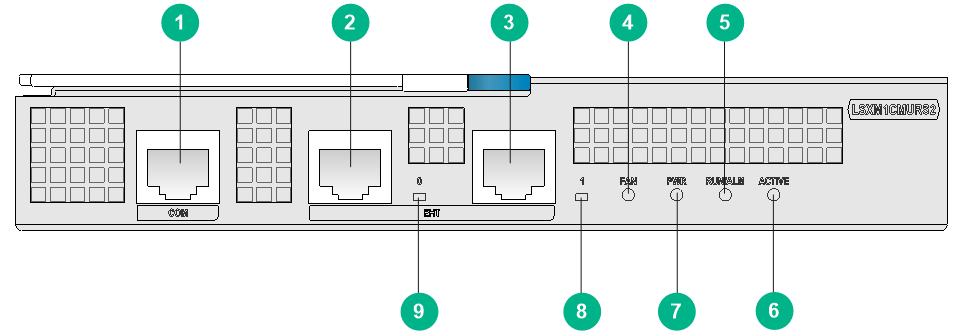
3 Front panel
Figure 1 Front panel
|
(1) COM port |
(2) 10/100/1000BASE-T management port (ETH) |
|
(3) 10/100/1000BASE-T management port (ETH) |
(4) Fan tray status LED |
|
(5) Module status LED |
(6) Active/standby status LED |
|
(7) Power supply status LED |
(8) 10/100/1000BASE-T management port status LED |
|
(9) 10/100/1000BASE-T management port status LED |
|
4 Specifications
Table 2 Module specifications
|
Item |
Specifications |
|
Processor |
Quad Core @ 2.2 GHz |
|
Memory |
8 GB |
|
Flash |
8 GB |
|
Power consumption |
22 W to 26 W |
|
LEDs |
· 2 × 10/100/1000BASE-T management port status LEDs · 1 × fan tray status LED · 1 × power supply status LED · 1 × module status LED · 1 × active/standby status LED For more information about the LEDs, see "LEDs." |
|
Operating temperature |
0°C to 40°C (32°F to 104°F) |
|
Operating humidity |
5% to 95%, noncondensing |
|
Ports |
· 1 × COM port (reserved) · 2 × 10/100/1000BASE-T management ports (reserved) |
|
Compatible device models |
S12508CR/S12516CR |
5 LEDs
The module provides LEDs to show the operating status of the modules and its ports.
Table 3 LED description
|
LED |
Status |
Description |
|
10/100/1000BASE-T management port status LED |
Steady green |
A link is present on the port. |
|
Off |
No link is present on the port. |
|
|
Flashing green |
The port is sending or receiving data. |
|
|
Fan tray status LED (FAN) |
Steady green |
All fan tray slots hold a fan tray, and all the fan trays are operating correctly. |
|
Steady red |
A fan tray slot is empty, or a fan tray is faulty. |
|
|
Power supply status LED (PWR) |
Steady green |
All the installed power supplies are operating correctly. |
|
Steady red |
A power supply is faulty. |
|
|
Module status LED (RUN/ALM) |
Steady green |
The module is starting up. |
|
Flashing green |
The module is operating correctly. |
|
|
Steady red |
The module is faulty. |
|
|
Active/standby status LED (ACTIVE) |
Steady green |
The module is in active mode. |
|
Off |
The module is in standby mode. |
|
|
IMPORTANT: · This module can be used only with the following modules: ¡ Type S supervisor engine units, for example, LSXM1SUPRS2. ¡ Type S interface modules, for example, LSXM3YGS48SF2. ¡ Type S fabric modules, for example, LSXM3SFS16F2. · To verify compatibility of the module with the software release you are using, see the release notes. · The module comes with the system software installed. By default, the module starts up with the installed system software after it is installed in the device. · The IPE file contains the software version for module upgrade. However, when you use the IPE file to upgrade the supervisor engine unit (also called MPU), the module will not be upgraded. To upgrade the module, execute the boot-loader update cmu command and then reboot the module by using the reboot cmu command. · The module is used in active/standby mode with another one. To upgrade the two modules, follow these guidelines: ¡ Before the upgrade, make sure the two modules are operating correctly, one in active mode and the other in standby mode. ¡ As a best practice, first upgrade the standby module and then the active module. ¡ The software versions of two modules might be different during the module upgrade process. Make sure the software versions of two modules are the same after the upgrade for high service availability. |
6 Related documentation
For information about installing the module, see H3C S12500CR Switch Routers Installation Guide.
Copyright © 2022 New H3C Technologies Co., Ltd.
The information in this document is subject to change without notice.
