- Released At: 30-07-2024
- Page Views:
- Downloads:
- Table of Contents
- Related Documents
-
TSN Technology White Paper
Copyright © 2024 New H3C Technologies Co., Ltd. All rights reserved.
No part of this manual may be reproduced or transmitted in any form or by any means without prior written consent of New H3C Technologies Co., Ltd.
Except for the trademarks of New H3C Technologies Co., Ltd., any trademarks that may be mentioned in this document are the property of their respective owners.
This document provides generic technical information, some of which might
not be applicable to your products.
Contents
Time synchronization technology implementation
H3C time synchronization solution
PTP (IEEE 802.1AS) phase synchronization operating mechanism
SyncE frequency synchronization operating mechanism
Data scheduling technology implementation
Packet enqueuing based on the flow characteristics
Configuring a gate control list
Data scheduling based on the gate control list
System configuration technology implementation
Pure distributed configuration model
Centralized network/distributed user configuration model
Pure centralized configuration model
SDN+TSN industrial Internet scenario
Overview
Background
In the era of Industry 4.0, the integration of Internet Technology (IT) and Operational Technology (OT) enables the manufacturing industry to fully leverage the advantages brought by digital transformation. By connecting production equipment, production workshops, enterprise management, and other levels of applications, as well as deploying edge computing services, data collection, transmission, visualization, and analysis can be achieved, thereby realizing intelligent manufacturing. However, in the actual process of promoting industrial Internet of Things (IIoT) and Industry 4.0, there are many obstacles to the integration of IT) and OT, including the following aspects:
· Complexity of the bus
Because each bus has different physical interfaces, transmission mechanisms, and object dictionaries, interoperability problems still exist even if various buses with Ethernet standards are used, such as Ethernet/IP, PROFINET, EtherCAT, Powerlink, and CC-Link IE. The complexity of the bus not only poses challenges for the OT end but also brings obstacles for information collection and instruction execution at the IT end. This makes it impossible for IT applications to achieve basic application data standards, such as big data analysis, order scheduling, and energy optimization. This lack of economy is not ideal for IT operating with scale effects. Therefore, although IT and OT convergence technology has been receiving attention, few companies have achieved significant growth in this field.
· Periodic and non-periodic data transmission
IT and OT have different data requirements, which necessitate different network transmission mechanisms for data transmission. For OT, its control tasks are periodic, so a periodic network transmission mechanism is required. Most of the control tasks in OT use a polling mechanism, that is, the master station assigns time slots to the backup stations. IT networks widely use the IEEE802.3 standard and adopt the CSMA/CD collision detection mechanism. Additionally, the data frames of standard Ethernet can support large-capacity data transmission such as Word documents, JPEG images, video, and audio.
· Differences in the real-time nature
Due to different real-time requirements, there are differences between IT and OT networks. For microsecond or millisecond level motion control tasks, the network is required to have very low latency and jitter, while IT networks usually do not have special requirements for real-time performance.
In such a context, the Time Sensitive Network (TSN) technology has emerged.
The history of TSN
TSN is a technology that extends from the audio and video field to the industrial, automotive, and mobile communication fields. It originated from the application requirements in the audio and video field, known as AVB (AudioVideo Bridging), used to address the high bandwidth, high real-time, and high transmission quality requirements of audio and video networks.
In 2006, the IEEE 802.1 working group established the AVB task group and successfully solved the problem of real-time synchronized transmission of audio/video data in networks, while also maintaining 100% backward compatibility with traditional Ethernet. Later, the automotive industry applied it to future advanced driver assistance systems (ADAS) and developed IEEE802.1AVB. In 2012, the AVB Task Group was renamed as the TSN Task Group, which is now known as TSN. The aim is to apply TSN technology to the fields of industrial automation, automotive, and mobile communication.
As shown in Figure 1, TSN is a standard protocol running at the data link layer in the network model. It aims to provide a set of universal time-sensitive mechanisms for the data link layer of Ethernet, ensuring deterministic Ethernet data communications time and enabling interoperability between different network protocols such as Ethernet/IP, PROFINET, EtherCAT, Powerlink, and CC-Link IE.

Technical advantages
TSN technology is applied in the manufacturing industry due to its following advantages:
· By integrating with OPC Unified Architecture (OPC UA), TSN can solve complex problems through a single network, achieving the integration of IT and OT as a whole.
· Support the transmission of periodic data and non-periodic data over the same network.
· Balance real-time performance and high-load data transmission requirements.
With the advantage of TSN technology, we deploy TSN network switches (switches that support TSN technology) in the industrial Internet environment to enable applications such as intelligent manufacturing, 5G integration, and unmanned driving.
Figure 2 TSN application diagram
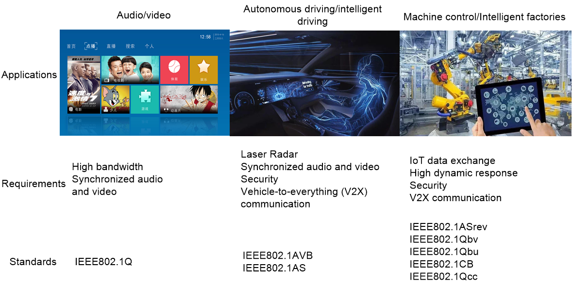
Network standards
TSN is a set of protocol standards that has high flexibility, allowing for the selection of corresponding protocol combinations based on application requirements.
|
|
NOTE: H3C has already implemented TSN standards including IEEE 802.1AS-Rev, IEEE 802.1Qbv, and IEEE 802.1Qcc. TSN standards currently under development include IEEE 802.1Qbu, IEEE 802.1Qch, and IEEE 802.1Qci. |
Table 1 shows the main TSN protocol standards involved in the industrial manufacturing field.
Table 1 TSN standard protocols that have been released
|
Standard |
Name |
Application field |
|
IEEE 802.1Qbv |
Scheduled Traffic |
Data scheduling |
|
IEEE 802.1Qbu |
Frame Preemption |
Data scheduling |
|
IEEE 802.1Qca |
Path Control and Reservation |
Data scheduling |
|
IEEE 802.1Qch |
Cyclic Queuing and Forwarding |
Data scheduling |
|
IEEE 802.1CB |
Frame Replication and Elimination for Reliability |
Seamless redundancy |
|
IEEE 802.1Qci |
Per-Stream Filtering and Policing |
Data scheduling |
|
IEEE 802.1CM |
Time-Sensitive Networking for Fronthaul |
Data scheduling |
|
IEEE 802.1Qcc |
Stream Reservation Protocol (SRP) Enhancements and Performance Improvements |
System configuration |
|
IEEE 802.1Qcp |
YANG Data Model |
System configuration |
|
IEEE 802.1AS-Rev |
Timing and Synchronization for Time-Sensitive Applications |
Time synchronization |
|
IEEE 802.1Qat |
Data scheduling |
|
|
IEEE 802.1.Qav |
Forwarding and Queuing Enhancements for Time-Sensitive Streams |
Data scheduling |
802.1Qbv
The core principle of TSN is time-based traffic scheduling and management. The concept of Time Aware Shaper (TAS) is proposed in a TSN network, which is a time-based queue scheduling method standardized as 802.1Qbv.
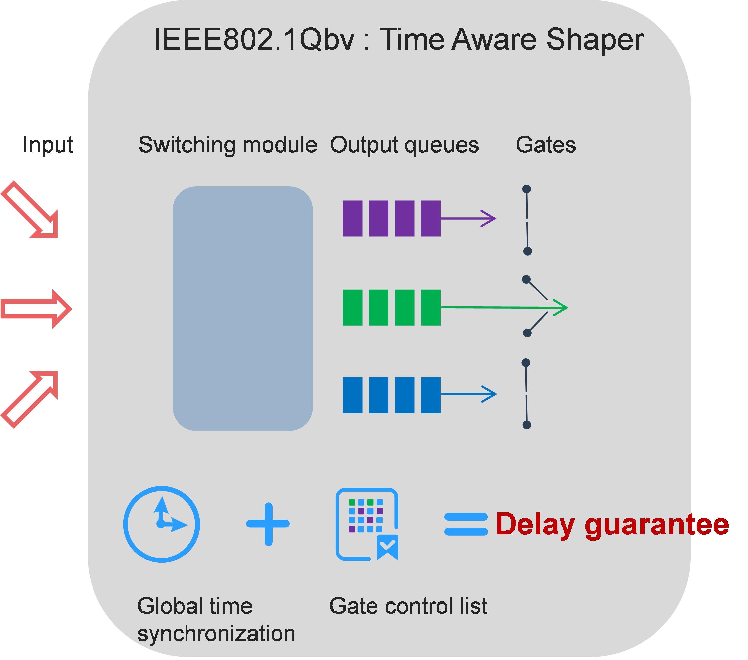
As shown in Figure 3, the data flow enters the TSN switch, and the devices map the time-sensitive flows and non-time-sensitive flows to different interface queues based on their characteristics. Then, the data flows in the queues is controlled by TAS. In TAS, a concept of a transport gate has been introduced, which has two states: open and closed. Data flows can only be transmitted when the state of the gate is open, and the gate state is defined in the gate control list. 802.1Qbv executes the gate control list in cycles, scheduling forwarding of packets in the queue, ensuring the bandwidth and delay for queues with strict transmission time requirements.
With the premise of synchronized network time, traffic forwarding in the network can achieve programmability and intelligence. First, the controller collects the traffic characteristics of critical flows and, combined with the network topology, calculates the optimal scheduling table for the overall network traffic. Then, the controller distributes the optimal scheduling table to TSN switches, ensuring critical traffic receives sufficient bandwidth and minimal delay.
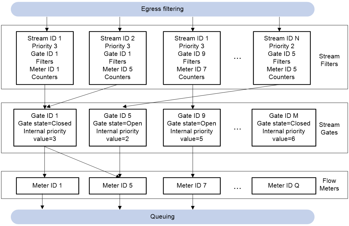
802.1Qci
802.1Qci is the Per-Stream Filtering and Policing (PSFP) protocol in the TSN protocol family. As shown in Figure 4, 802.1Qci uses stream IDs to identify individual streams, and then filters, gate controls, and monitors each stream to ensure that the filtered data is forwarded at the specified time.
Figure 4 802.1Qci principle diagram
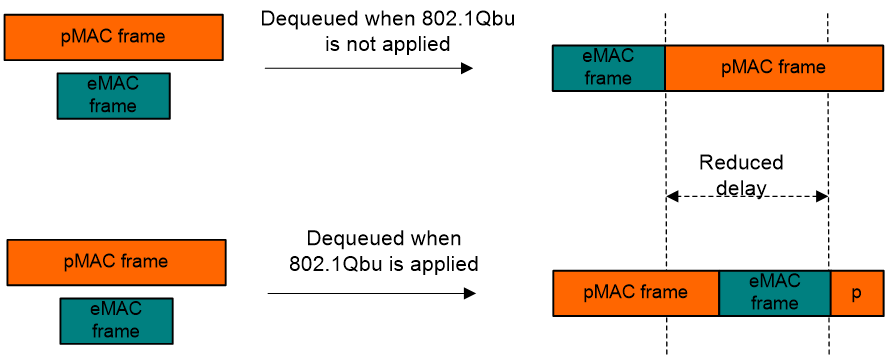
802.1Qbu
To solve the potential issue in 802.1Qbv that the continuous transmission of low-priority frames in a queue hinders the timely transmission of high-priority frames, TSN introduced frame preemption mechanisms (802.1Qbu and 802.3br) to interrupt the transmission of standard Ethernet or large frames, allowing the transmission of high-priority frames. Afterward, the interrupted frames can be transmitted again.
As shown in Figure 5, 802.3br divides the given bridge egress into two MAC services, namely preemptable MAC (pMAC) and express MAC (eMAC). Based on the implementation of 802.3br, 802.1Qbu divides data packets into pMAC frames and eMAC frames according to their priority levels. A transmitting pMAC frame can be preempted by an eMAC frame. After the transmission of the eMAC frame is complete, the transmission of the pMAC frame can be restored.
Figure 5 802.Qbu principle diagram
802.1Qch
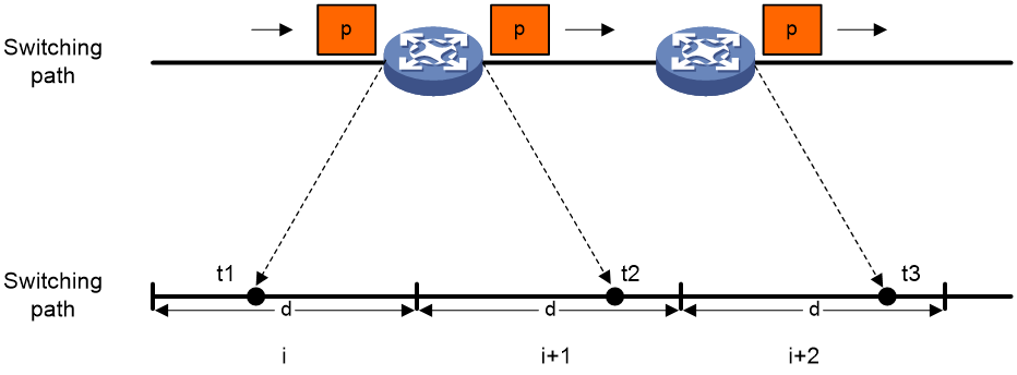
802.1Qch defines various configuration methods for PSFP mechanisms, among which cyclic queuing and forwarding (CQF) is the only configuration method specified in the TSN protocol. The biggest feature of the CQF model is simple calculation and configuration, which ensures deterministic latency for end-to-end packet switching. The main operating principles of the CQF model include the following parts:
· Delay guarantee
As shown in Figure 6, the CQF model divides the entire network time into continuous time slots with a length of d, denoted as i, i+1, ..., i+N. If a switch receives a data frame from the link at time t1 in time slot i, the frame must be output to the link at some time t2 in time slot i+1. Therefore, the delay t2-t1 of the frame has an upper limit of 2d and a lower limit of 0. Based on the CQF model, the maximum delay for frame exchange in the network is (h+1) x d, and the minimum delay is (h-1) xd, where h is the number of hops on the transmission path.
· Time-sensitive frame processing
TSN switches supporting the CQF model require the configuration of two scheduler-based queues, Q0 and Q1, on the egress interface. During even time slots, queue Q0 only receives frames and does not send frames, while queue Q1 only sends frames and does not receive frames. During odd time slots, queue Q0 only sends frames and does not receive frames, while queue Q1 only receives frames and does not send frames. Receiving and sending operations are performed in a cycle by two queues.
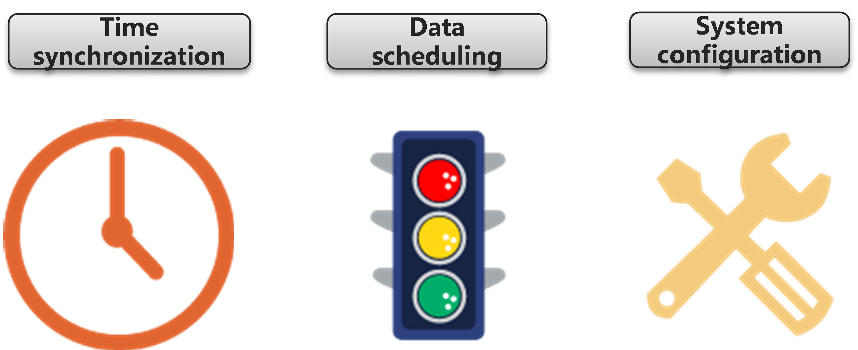
Operating mechanism
The core implementation of H3C TSN technology can be summarized into three parts: time synchronization, data scheduling, and system configuration.
Figure 7 H3C TSN switch core implementation diagram
As shown in Table 2, to better understand the TSN technology, we will draw an analogy between the TSN technology and the operation mechanism of high-speed rail networks.
Table 2 TSN network and high-speed rail network
|
Event |
High-speed rail network |
TSN network |
Related TSN standards |
|
Time synchronization |
All stations synchronize time using standard Beijing Time. |
All switches and interfaces in the TSN network must ensure precise time synchronization. |
IEEE 802.1AS |
|
Operational planning |
Offline determination of high-speed rail operation plans, including departure times and arrival times. |
Obtain the characteristics (cycle, data size) of time-sensitive flows in advance and allocate resources to calculate the network-wide time slot allocation. |
IEEE 802.1Qcc or employing SDN centralized control mechanism |
|
Access control |
According to the time information specified in the operating schedule, control the train to stop at the designated platform after entering the station through the control system. |
Switches identify each packet and control their entrance into specific output queues based on globally synchronized deterministic time. |
IEEE 802.1Qci |
|
Exit control |
According to the time information specified in the operating schedule, the departure time of the train is controlled through the train control system. |
Switches schedule packets from output interfaces at deterministic time points based on network-wide synchronized time. |
IEEE 802.1Qbv |
|
Avoidance mechanism |
During train conflicts, the slow train needs to wait and yield to the fast train on the platform, ensuring the fast train's punctual passage. |
When a time-sensitive packet reservation transmission event arrives, it can interrupt the ongoing transmission of other low-priority packets, ensuring the transmission of time-sensitive packets. |
IEEE 802.1Qbu |
Time synchronization technology implementation
Concepts
Time synchronization is generally divided into frequency synchronization and phase synchronization. Different networking environments require different synchronization methods.
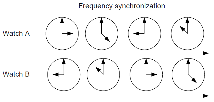
Frequency synchronization
Frequency synchronization is also known as clock synchronization. Frequency synchronization refers to the same or fixed proportional change in frequency between two signals, while maintaining a constant phase difference between the signals. As shown in Figure 8, the time of the two tables is different, but there is a constant difference of 6 hours.
Figure 8 Frequency synchronization
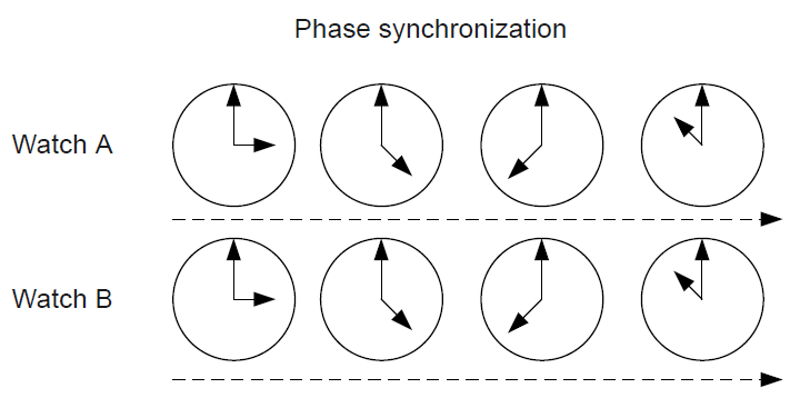
Phase synchronization
Phase synchronization refers to the frequency and phase of signals being consistent with each other, with the phase difference between signals remaining constant at zero. As shown in Figure 9, the time of both tables remains consistent at all times. Phase synchronization is based on frequency synchronization, so phase synchronization is also known as time synchronization.
Figure 9 Phase synchronization
Technology comparison
Time synchronization solution
H3C supports multiple time synchronization solutions. The comparison between different solutions is as follows:
Table 3 Time synchronization solution comparison
|
Time synchronization solution |
Frequency synchronization |
Phase synchronization |
Time synchronization accuracy Precision |
Description |
|
GPS |
Supported |
Supported |
≤ 100 nanoseconds |
Time synchronization is achieved by carrying frequency and phase information through electromagnetic waves. In recent years, the accuracy of GPS has been continuously improved, but it still relies on US GPS technology. |
|
BDS |
Supported |
Supported |
Nanosecond level |
Time synchronization is achieved by carrying frequency and phase information through electromagnetic waves. Currently, the BDS synchronous network is under construction, and by 2035, it will achieve "full coverage and substitutability." |
|
SyncE |
Supported |
Not supported |
Time synchronization not supported |
Frequency synchronization is achieved by using the physical layer bitstream to carry and recover frequency information. |
|
NTP |
Not supported |
Supported |
Millisecond level |
By transmitting phase signals through NTP packets, phase synchronization can be achieved but cannot meet the microsecond-level time synchronization accuracy requirements for wireless access networks. |
|
PTP |
Supported |
Supported |
Sub-microsecond level or even tens of nanoseconds |
By transmitting frequency and phase information through PTP messages, high-precision time synchronization is achieved in conjunction with hardware. With the advancement of software and hardware technologies, the precision of PTP can reach several tens of nanoseconds or even higher. |
PTP protocol comparison
IEEE 1588 is the foundational protocol for Precision Time Protocol (PTP), which specifies the principles and message-handling rules for high-precision clock synchronization in networks. It was initially used in industrial automation and is now primarily used for bridging local area networks. Therefore, PTP is also known as IEEE 1588, abbreviated as 1588. 1588 has two versions, 1588v1 and 1588v2. 1588v1 can only achieve sub-millisecond level time synchronization accuracy, while 1588v2 can achieve sub-microsecond level synchronization accuracy and can simultaneously achieve phase synchronization and frequency synchronization. Currently, 1588v2 has a wider application than 1588v1.
Based on IEEE 1588, PTP has also spawned protocols such as IEEE 802.1AS. Different PTP protocol standards have different usage scenarios and functional differences, but the basic principles are similar.
Table 4 PTP protocol comparison
|
Use scenario |
Main differences |
|
|
IEEE 1588v2 |
Wide applicability, no mandatory requirements for network environment, flexible scalability according to different application environments. |
· Using the Best Master Clock (BMC) algorithm to calculate the master-backup relationship. · Link latency measurement mechanisms support the end delay mechanism and request-response mechanism. · Protocol packets support IEEE 802.3/Ethernet encapsulation and UDP encapsulation. |
|
IEEE 802.1AS |
The implementation of 1588v2 in bridged LAN has been refined, supporting point-to-point full-duplex Ethernet links, IEEE 802.11 links, and IEEE 802.3 EPON links. |
· Based on the MSTP algorithm, the calculation of the master/subordinate relationship is faster compared to 1588v2, because the MSTP algorithm is faster than the Announce message sending interval. · The link delay measurement mechanism only supports the end delay mechanism, with a shorter period than the Pdelay_Req and Sync messages sent in 1588v2. The calculation of link delay and the time offset between the master and subordinate is faster, resulting in more stable time synchronization. · Protocol packets support only IEEE 802.3/Ethernet encapsulation. |
H3C time synchronization solution
Time synchronization is the foundation for achieving deterministic communication in TSN networks. Time synchronization provides a time reference for scheduling traffic among nodes in a TSN network.
H3C provides users with a comprehensive solution of "SyncE frequency synchronization + PTP phase synchronization" to achieve high-precision (nanosecond-level) time synchronization. The advantages of this solution are:
· Higher precision: Achieve frequency synchronization through SyncE, with higher precision than PTP frequency synchronization, enabling the overall solution to achieve nanosecond-level time synchronization. In theory, it is possible to ensure time synchronization error within 1μs. Currently, H3C can achieve 30ns.
· More reliable:
¡ SyncE and PTP both have frequency synchronization capabilities. Devices preferentially use SyncE as the primary method for frequency synchronization. If the SyncE clock source fails or there is a link failure resulting in the loss of frequency synchronization signals, the device will use PTP frequency synchronization.
¡ SyncE and PTP can share clock sources or use independent clock sources. When the PTP function fails and causes the loss of PTP time signals, SyncE can still work, and each device can maintain frequency synchronization. The time offset of each device can still be controlled within an acceptable range.
PTP (IEEE 802.1AS) phase synchronization operating mechanism
Frequency synchronization
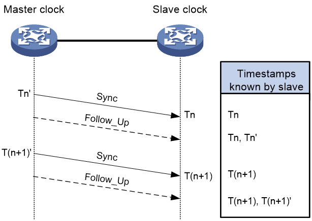
After determining the grandmaster clock and the master/subordinate relationship between clock nodes based on the BMC algorithm, the master clock and the subordinate clock exchange Sync messages to achieve frequency synchronization. The master clock periodically sends Sync messages to the subordinate clock. If we ignore changes in link delay and assume that the frequency of the subordinate clock is synchronized with the master clock, the accumulated time offset between the master clock and the subordinate clock should be the same during the same time interval (T(n+1) - Tn = T(n+1)' - Tn'), as shown in Figure 10. If the time offset is not the same:
· If T(n+1) - Tn > T(n+1)' - Tn', the time of the subordinate clock is slower than the master clock and the frequency is faster than the master clock. In this case, slow down the frequency of the subordinate clock.
· If T(n+1) - Tn < T(n+1)' - Tn', the time of the subordinate clock is faster than the master clock, but the frequency of the subordinate clock is slower than the master clock. In this case, increase the frequency of the subordinate clock.
The frequency ratio calculation formula is: (T(n+1) - Tn) / (T(n+1)' - Tn'). The subordinate clock adjusts its frequency according to the frequency ratio calculated.
Figure 10 PTP two-step mode frequency synchronization principle
Phase synchronization
After confirming the grandmaster clock and the master-subordinate relationship between clock nodes, the phase synchronization between the master and subordinate clocks will commence. Master and subordinate clocks exchange PTP messages periodically, and the subordinate clock calculates the current time offset from the master clock through timestamps. The subordinate clock adjusts local time based on the time offset to keep local time consistent with the master clock, also known as time synchronization.
The local accurate time of the subordinate clock is equal to its current local time minus the time offset.
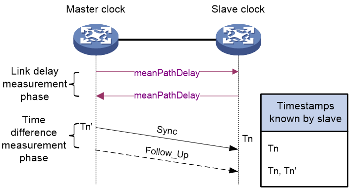
As shown in Figure 11, roughly calculated, the time offset = Tn - Tn'. But in fact, (Tn - Tn') includes the transmission delay of the message on the link. In order to improve the accuracy of time synchronization, the measurement and calculation process of the time offset includes the following two stages:
Link delay measurement phase: This phase is used to determine the delay of message transmission between the master clock and the subordinate clock. The time synchronization messages between the master and subordinate clocks are exchanged and the transmission and reception times of the messages are recorded. The round-trip delay between the master and subordinate clocks is calculated by computing the time difference between the messages' round-trip times. If the link delays in both directions are the same (also known as network symmetry), half of the total round-trip link delay is the one-way link delay (meanPathDelay). If the network delay is asymmetric and the difference in link delay between the sender and receiver directions is known through other means, asymmetric delay can be configured to correct the link delay and achieve more accurate time synchronization.
Time offset measurement phase: This phase is used to measure the time offset between the master clock and the subordinate clock. The master clock periodically sends Sync messages to the subordinate clock and records the sending time Tn'. When receiving a Sync message from the master clock, the subordinate clock immediately records the current time Tn, thus obtaining the time offset between the master and subordinate clocks according to the formula: time offset = (Tn-Tn') - one-way link delay.
Figure 11 Phase synchronization stage
SyncE frequency synchronization operating mechanism
Clock source type
A device that provides clock signals to other devices is called a clock source. Depending on the source of the clock signal, the clock sources supported by SyncE include:
· BITS (Building Integrated Timing Supply System) clock source: The clock signal is generated by dedicated BITS clock devices. The device exchanges BITS clock signals through a dedicated interface (BITS interface).
· Line clock source: The clock signal extracted from the Ethernet line stream by the clock monitoring module of the device, provided by the upstream device, that is, the clock signal transmitted on the interface with the SyncE function enabled. The accuracy of the line clock source is lower than that of the BITS clock source.
· PTP clock source: Time signal extracted from PTP protocol messages by the device. The accuracy of the PTP clock source is lower than that of the BITS clock source.
· Local clock source: The 38.88 MHz clock signal generated by the internal crystal oscillator of the device, typically with the lowest precision.
Clock source selection
When multiple clock sources are connected to a device and there are multiple clock signal input devices, the highest priority clock signal can be selected as the grandmaster clock (also known as a reference source) through manual or automatic mode.
· Manual mode: Users manually specify the grandmaster clock. If the synchronization signal of the grandmaster clock is lost, the device will not automatically adopt the clock signal from other clock sources, but will continue to operate with the clock parameters of the lost grandmaster clock stored on the device.
· Automatic mode: The system automatically selects the grandmaster clock (also known as automatic source selection). If the synchronization signal of the grandmaster clock is lost, the device will automatically select a new grandmaster clock and synchronize with it.
Automatic source selection reference factors
The factors that affect the device's automatic selection of the grandmaster clock include SSM (Synchronization Status Message) level and priority.
SSM level
SSM is a set of status information for Quality Level (QL) of the clock source, defined in ITU-T G.781 in the Synchronous Digital Hierarchy (SDH) network. SyncE also uses SSM levels to indicate the quality of clock sources, and refers to SSM levels as QL levels, which are collectively referred to as SSM levels in this article.
Priority
The priority of a clock source is an attribute specified by the user on the device for each clock source. Users configure the priority for BITS, PTP, and line clock sources through the CLI. This priority is locally effective and will not be propagated to neighboring devices.
By default, the priority of a clock source is 255 and cannot participate in the selection of the grandmaster clock. If you want the clock source to participate in the election of the grandmaster clock, you need to assign a priority other than the default to it. The smaller the priority value of the clock source, the higher the priority. Among the various types of clock sources supported by the device, the local clock has the lowest priority and does not support configuration.
Automatic source selection mechanism
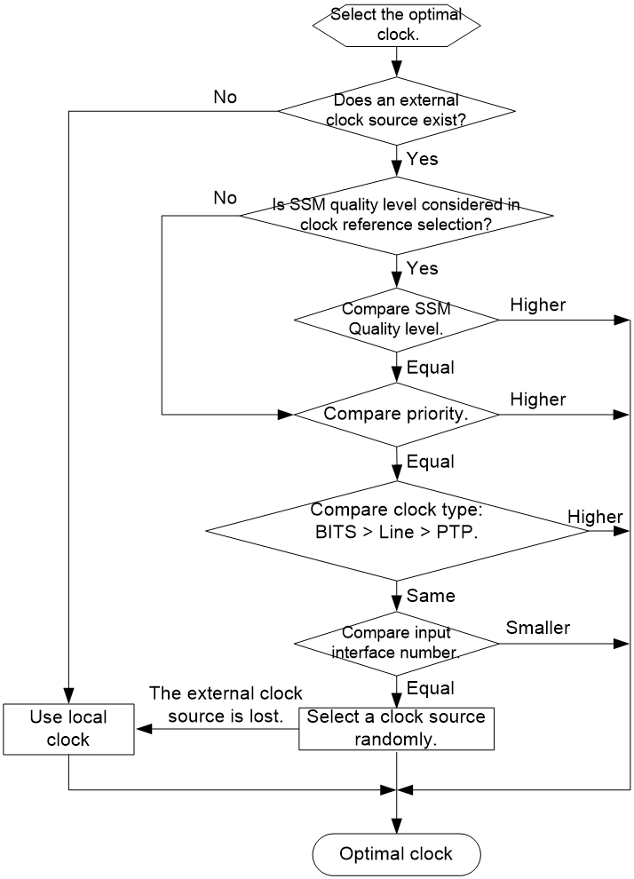
As shown in Figure 12, SyncE automatically selects the grandmaster clock for the device according to the following principles:
The clock source with the highest SSM level is selected as the grandmaster clock.
If the user configures the SSM level not to participate in automatic source selection, or if the SSM levels are the same, the source selection will be based on the priority of the clock source, and the clock source with the smallest priority value will be selected first.
If the priorities of the clock sources are the same, select the clock source according to its type. The BITS clock source, the line clock source, and the PTP clock source are in descending order of priority.
If the types of clock sources are also the same, continue comparing the interface numbers of the clock signal inputs, and the clock source with the smallest number is selected.
When the BITS clock source, line clock source, and PTP clock source are all unavailable, the local clock source is used.
After the grandmaster clock is elected, the device will use ESMC messages to pass on the SSM level of the grandmaster clock to downstream devices, further influencing the selection of the grandmaster clock for downstream devices.
If an interface's received clock signal is elected as the grandmaster clock, and the interface does not receive an ESMC message within 5 seconds, the device will consider the grandmaster clock as lost or unavailable, and will automatically reselect the grandmaster clock according to the preceding principles. When the grandmaster clock source is restored, the system automatically switches back to the original grandmaster clock.
Figure 12 Automatic source selection flowchart
Frequency synchronization
After selecting the grandmaster clock, the device begins to lock on to it and perform clock synchronization (frequency synchronization).
In a digital communication network, PCM (Pulse Code Modulation) digital pulse signals are transmitted. The frequency of the pulses refers to the number of pulses generated per second. The Ethernet physical layer encoding uses Fast Ethernet (100 Mbps) and Gigabit Ethernet (1 Gbps) technologies. An additional bit is inserted every 4 bits on average, so that there are no consecutive bit streams of more than 4 ones or 4 zeros in the transmitted data stream, which effectively includes clock information. Using this information transmission mechanism, SyncE uses a high-precision clock to send data on the Ethernet source interface, and recovers and extracts this clock at the receiving end to serve as the baseline for sending data streams at the receiving end.
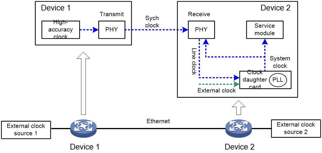
As shown in Figure 13, external clock source 1 is more reliable than external clock source 2 and is selected as the grandmaster clock. Device 1 and Device 2 both synchronize with the frequency of external clock source 1. The synchronization principle is as follows:
Synchronization mechanism at the sending end
The sender carries and transmits synchronization information:
Because the SSM level of external clock source 1 is the highest, Device 1 selects external clock source 1 as the grandmaster clock.
Device 1 extracts the clock signal sent by external clock source 1 and injects the clock signal into the PHY chip of the Ethernet interface card.
The PHY chip adds this high-precision clock information to the serial data stream of the Ethernet cable and sends it out to downstream device Device 2.
Synchronization mechanism at the receiving end
The receiving end extracts and synchronizes clock information:
The PHY chip on the Ethernet interface card of Device 2 extracts clock information from the serial stream received from the Ethernet line, which is then divided and fed to the clock synchronization board.
The clock board compares the clock signal received from the interface, the clock signal input from the external clock source 2, and the clock signal generated by the local crystal oscillator. It selects the grandmaster clock signal based on an automatic source selection algorithm and sends the clock signal to the phase-locked loop (PLL) on the clock board.
After tracking the clock reference source, the PLL synchronizes the local system clock and injects it into the Ethernet interface card PHY chip for downstream transmission. At the same time, it outputs the local system clock for use by the business modules of the device.
Figure 13 SyncE clock synchronization principle
Data scheduling technology implementation
Introduction
Data scheduling is the core for achieving deterministic communication in TSN networks.
In TSN networks, it is important not only to ensure the arrival of time-sensitive data flows but also to guarantee low-latency transmission for these flows. By optimizing the scheduling order of time-sensitive flows, non-time-sensitive flows, and different time-sensitive flows through control devices, TSN meets the time requirements of different data flows. This process is called traffic shaping. The data scheduling in TSN networks is the process of traffic shaping.
H3C implements the process of shaping traffic through TAS (Time Aware Shaper) on TSN switches according to the standard IEEE802.1Qbv protocol.
Application scenarios
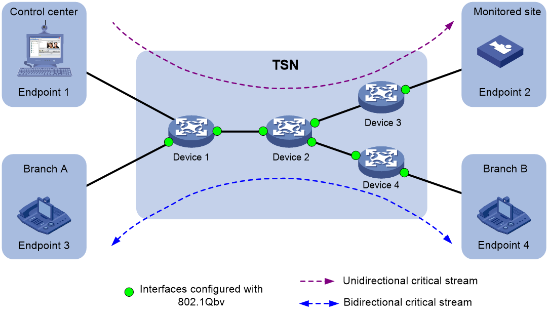
As shown in Figure 14, Endpoint 1 needs to issue commands to control the startup and shutdown parameters of Endpoint 2. The commands issued by Endpoint 1 need to traverse the Ethernet to reach Endpoint 2. At the same time, an important video conference is taking place between Endpoint 3 and Endpoint 4, and both directions of the video stream have high requirements for network latency and jitter. Ethernet has the risk of latency uncertainty and even packet loss. By deploying the 802.1Qbv function on the packet ingress/egress interfaces of Device 1, Device 2, Device 3, and Device 4, you can control the latency within the microsecond level for critical service flows, providing significant assurance for real-time transmission between point-to-point connections on the network.
Figure 14 802.1Qbv application scenario
Basic concepts
Forwarding queue
To avoid packet loss caused by network congestion, the switching chip on the interface card uses forwarding queues to send packets. Each interface has eight forwarding queues, with queue IDs ranging from 0 to 7. When an interface needs to send a packet, the packet is first placed into the corresponding queue according to certain rules. For packets in the same queue, the packet that is first in is given priority for forwarding.
TSN flow
A TSN flow is the critical traffic flow that requires deterministic transmission in a TSN network. After receiving a packet, an interface determines whether the flow is a TSN flow based on the flow characteristics, including the source MAC address, destination MAC address, and VLAN ID. The more flow characteristics specified on an interface, the more accurate the matching will be.
Gate control list
A TSN flow implements the scheduling of interface forwarding queues and packet forwarding based on gate control lists.
The gate control list contains multiple gate operations. A gate operation consists of three attributes that define a gate operation:
· Gate operation number: The corresponding number for a gate operation is 1 to N. 802.1Qbv schedules the gates in ascending order according to the gate operation numbers.
|
|
NOTE: H3C IE4320-10S/ IE4320-10S-UPWR TSN switches support a maximum of 16 gate operations. The number of gate operations supported by a device depends on the device model. |
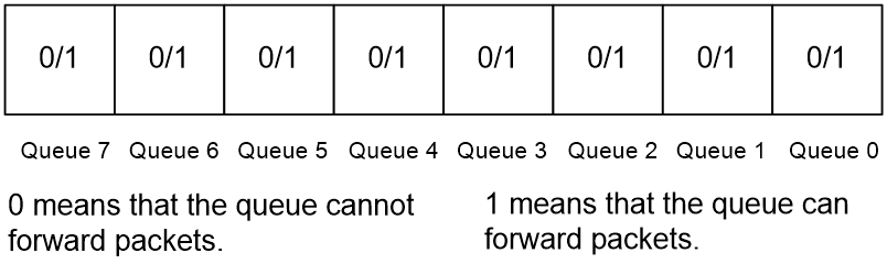
· Gate state: As shown in Figure 15, the gate status of a forwarding queue is represented by an 8-bit binary string (XXXXXXXX). Starting from the right to the left, the rightmost bit indicates the switch status of queue 0, the second rightmost bit indicates the switch status of queue 1, and so on. If a bit is 1, the gate state of the corresponding queue is open. If a bit is 0, the gate state of the corresponding queue is closed.
· Gate state duration: The duration of the gateway state during a gate operation. When the time is reached, the next gate operation will be executed.
As shown in Figure 16, the user has defined the queue gate state and the duration of gate state for gate operation numbers 2, 4, and 5. For gate operations 1 and 3, which are not defined by the user, the system will use the default queue gate state and the default duration of the gateway state.
Figure 16 TSN flow forwarding and scheduling gate control list diagram
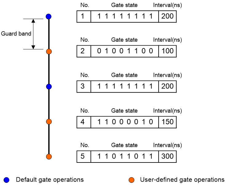
Guard band
As shown in Figure 16, the 802.1Qbv guard band is the buffer time between the two gate operations in the TSN flow forwarding scheduling gate control list.
The guard band is used to ensure that the device can fully transmit the current data frame being sent when performing 802.1Qbv forwarding queue scheduling. For example, when an interface is forwarding 802.1Qbv tagged flows and a data frame is sent halfway, and the duration of the sustained state of the forwarding queue gate is reached. At this time:
· If the 802.1Qbv guard band feature is disabled, 802.1Qbv will immediately perform the next gate operation, causing the content of the data frame being currently transmitted to be truncated. The remaining content might be discarded or need to wait for the next polling cycle to be sent.
· If the 802.1Qbv guard band feature is enabled, 802.1Qbv will send the remaining part of the data frame before proceeding to the next gate operation.
· The device has already defined default guard band durations for each interface at the time of manufacturing, which are not configurable.
Cycle time
802.1Qbv periodically executes the gate control list, and the cycle time is the duration for the system to perform the gate control list once. An interface starts timing from the execution of the first 802.1Qbv gate operation and executes all gate operations in ascending order according to their operation numbers. When the cycle time is reached, it will automatically restart the execution of the gate control list from the first gate operation.
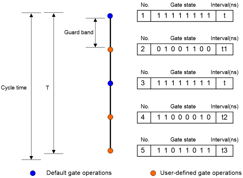
As shown in Figure 17, the time required for one round of all gate operations in the gate control list (T) = t+Guard band+t1+Guard band+t+Guard band+t2+Guard band+t3. The cycle time is determined by the duration of the switch state and the guard band. To ensure that the interface can send out packets for all queues according to the gate control list, T needs to be greater than or equal to the cycle time. Otherwise, once the cycle time is over, the interface will restart and execute the next round of the gate control list, which might result in some gate operations not being executed.
Figure 17 Relationship between cycle time, gateway state duration, and guard band
Base time
The base time is the time when the interface starts executing the 802.1Qbv forwarding queue scheduling strategy, which is used to calculate when the device performs the scheduling algorithm.
For example, if the user plans to execute the 802.1Qbv scheduling algorithm starting from 12:00:00 on March 18, 2021, the user needs to calculate the time difference between this time and the base time of January 1, 1970, 00:00:00. Then, convert it to PTP time format (in seconds and nanoseconds) and use the converted seconds and nanoseconds for base time configuration.
Operating mechanism
The entire data scheduling process is divided into the following three parts:
1. Packet enqueuing based on the flow characteristics.
2. Configure a gate control list.
3. Data scheduling based on the gate control list.
Packet enqueuing based on the flow characteristics
Flow characteristics are the basis for differentiating critical business traffic in 802.1Qbv.
802.1Qbv supports matching critical business packets using source MAC address, destination MAC address, CoS value, and VLAN ID. The more specified parameters, the more accurate the matching. After data flows enter the TSN switch, the devices map TSN flows and non-TSN flows to different interface queues based on their flow characteristics, and then control the data flows in the queues through TAS.
Configuring a gate control list
As shown in Figure 18, each interface has a gate control list to control 8 forwarding queues. A gate control list is an ordered set of gate operations, and each gate operation corresponds to the gate state and the duration of the gate state for eight forwarding queues on an interface. Configuring the gate control list refers to arranging gate operation IDs, gateway states, and the gateway state duration on the interface. The device supports arranging the gate control list through CLI and CNC (Centralized Network Configuration).
Figure 18 Gate control list diagram
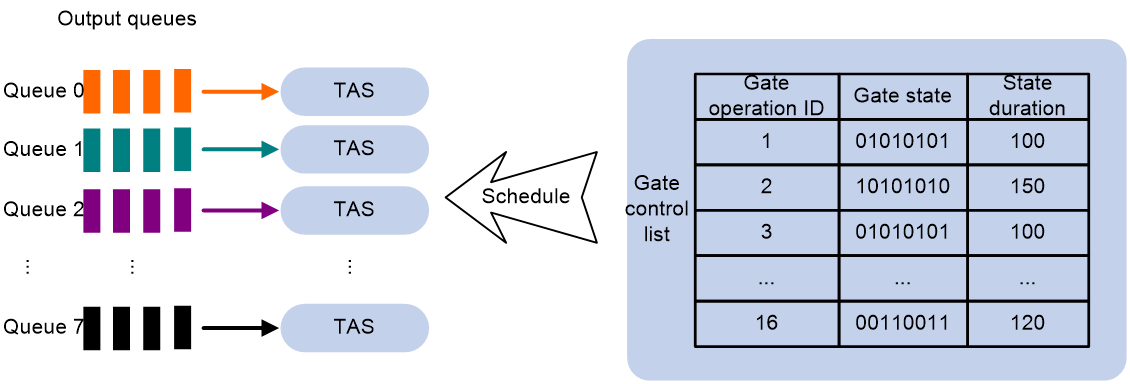
H3C IE4320-10S/ IE4320-10S-UPWR TSN switches support TAS with eight queues in the egress direction. Within one scheduling cycle, the switch supports a maximum of 16 gate operations, with a minimum gate duration of 8ns and a maximum of 256us.
Data scheduling based on the gate control list
802.1Qbv periodically performs gate control list execution. The gate operations are executed in ascending order of gate operation numbers in the gate control list. This enables the scheduling of data flows in interface queues, achieving low-latency transmission of TSN flows.
System configuration technology implementation
Concepts
In TSN networks, each specific application has its own time requirements. System configuration refers to the process of TSN configuration for each node in the TSN network based on application-specific timing requirements. It involves the rational allocation of resources on the network paths to ensure the smooth operation of all requirements as expected.
H3C implements system configuration by using the standard IEEE802.1Qcc protocol. IEEE802.1Qcc defines a unified interface for User and Network. User refers to Talker and Listener, while Network refers to the devices that transmit the Talker-to-Listener packets.
Configuration models
IEEE802.1Qcc defines three TSN control plane architectures: pure distributed configuration model, centralized network/distributed user configuration model, and pure centralized configuration model.
Pure distributed configuration model
In the pure distributed model, user requirements are transmitted between Listeners, Bridges, and Talkers via the TSN UNI (User/Network Info) protocol. Each Listener, Bridge, and Talker independently complete TSN configuration based on the TSN UNI protocol, without a centralized network configuration entity.
Figure 19 Pure distributed configuration model

· User requirement collection: Bridges interact with Listeners/Talkers through a TSN UNI protocol (for example, SRP protocol) to complete user requirement collection, as shown in the solid arrow part in Figure 19.
· TSN network configuration: Each Bridge completes the TSN configuration distribution on the local device through the TSN UNI protocol, as shown in the dashed arrow section in Figure 19.
Centralized network/distributed user configuration model
In the centralized network/distributed user configuration model, Bridges collect user requirements by interacting with Listeners/Talkers through a TSN UNI protocol, and act as proxies to send user requirements to CNC.
CNC uses remote management protocols (such as SNMP, NETCONF, and Restconf) to discover network topology and obtain TSN attributes of devices. According to user requirements and device TSN attributes, CNC will remotely distribute the computed gate control list to the Bridges using a remote management protocol.
Figure 20 Centralized network/distributed user configuration model
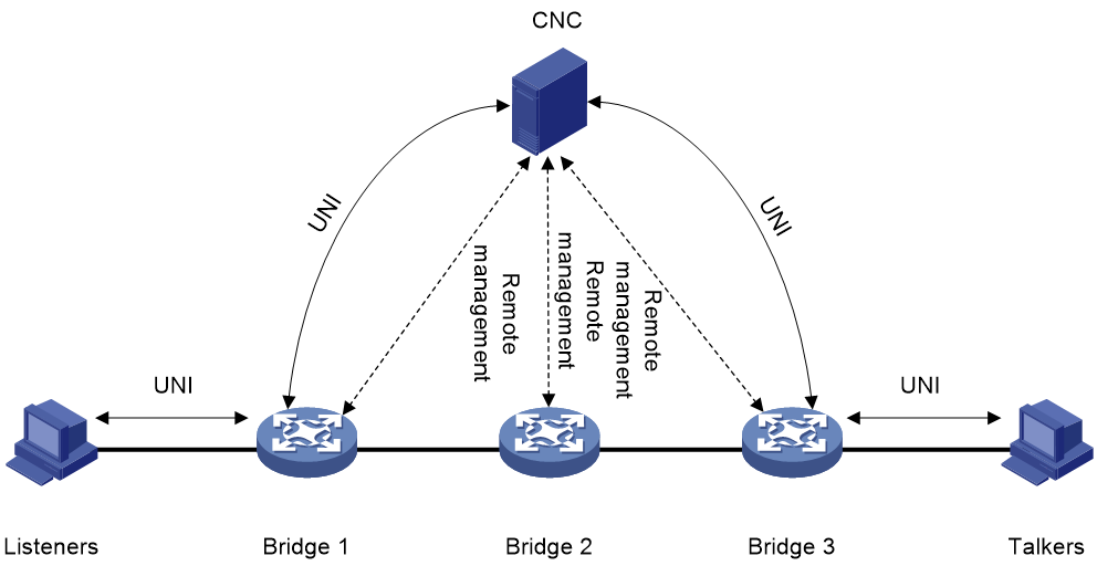
· User requirements collection: Bridges collect user requirements through interaction with Listeners/Talkers using a TSN UNI protocol (such as SRP protocol) and acts as an agent to send user requirements to CNC. The interaction process is shown in the solid line arrow portion in Figure 20.
· TSN network configuration: CUC discovers network topology and retrieves TSN attributes of devices through a remote management protocol. Then, CUC uniformly distributes the calculated gate control list to Bridges, as shown in the dashed arrow section in Figure 20.
Pure centralized configuration model
In the pure centralized configuration model, CUC is used to discover Listeners and Talkers, and collect the capabilities and user requirements of Listeners and Talkers. CNC obtains user requirements by interacting with CUC through a TSN UNI protocol.
CNC uses remote management protocols (such as SNMP, NETCONF, and Restconf) to discover network topology and obtain TSN attributes of devices. According to user requirements and device TSN attributes, CNC will remotely distribute the computed gate control list to the Bridges using a remote management protocol.
Figure 21 Pure centralized configuration model
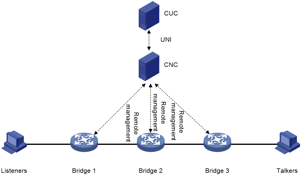
· User requirement collection: CNC interacts with CUC through a TSN UNI protocol to obtain user requirements, as shown in the solid arrow part in Figure 21.
· TSN network configuration: CUC discovers network topology and retrieves TSN attributes of devices through a remote management protocol. Then, CUC uniformly distributes the calculated gate control list to Bridges, as shown in the dashed arrow section in Figure 21.
Typical application scenario
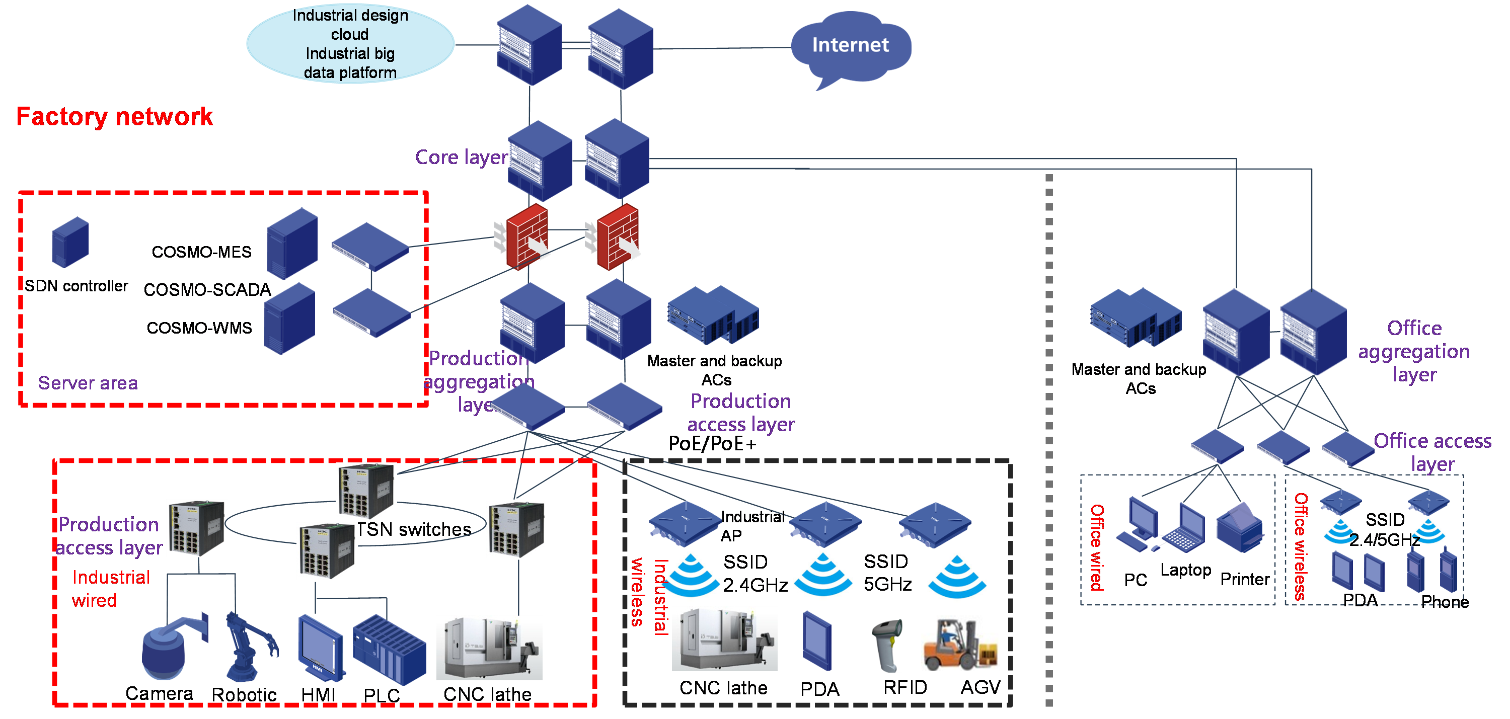
SDN+TSN industrial Internet scenario
As shown in Figure 22, the entire industrial campus can adopt the H3C TSN+U-Center management architecture to establish the TSN network and achieve interconnection between the production network and the office network.
On one hand, the TSN network can ensure the real-time and deterministic transmission of time-sensitive data in production networks for control and real-time operation. On the other hand, it can ensure the mixed transmission of various types of service traffic on the public network, better connecting the deployed industrial Ethernet, Internet of Things, and new industrial applications, and achieving high-quality carriers and interconnection under various traffic models.
The deployment of the H3C TSN+U-Center management architecture in the industrial Internet has the following advantages:
· Deploy the U-Center solution on TSN switches for centralized resource and service management. This greatly enhances the intelligent and flexible networking capabilities of factory networks, providing visual management, intelligent scheduling, improved application experience, and streamlined operation and maintenance.
· Deploy ERP/PLM/SCM/CRM/MES systems, cloud computing platforms, and security situation awareness platforms in the office network to achieve functions such as remote equipment efficiency visualization, industrial cloud data collection and analysis, and security monitoring.
· Deploy firewall devices on the outbound direction between the factory and the external network to ensure network security.
Figure 22 U-Center+TSN typical industrial Internet networking diagram
References
· Time Sensitive Networking (TSN) Industry White Paper (Draft for Comments)
· 802.1Qbv-2015
· 802.1Qcc-2018
· 802.1Qci-2017
· 802.1Qbu-2016
Abbreviation
|
Abbreviation |
Full name |
|
TSN |
Time Sensitive Network |
|
AVB |
AdioVideo Bridging |
|
IT |
Internet Technology |
|
OT |
Operational Technology |
|
OPC UA |
OPC Unified Architecture |
|
TAS |
Time Aware Shaper |
|
PSFP |
Per-Stream Filtering and Policing |
|
pMAC |
Preemptable MAC |
|
eMAC |
Express MAC |
|
CQF |
Cyclic queuing and forwarding |
|
PTP |
Precision Time Protocol |
|
SyncE |
Synchronous Ethernet |
|
BITS |
Building Integrated Timing Supply System |
|
CNC |
Centralized Network Configuration |
|
UNI |
User/Network Info |
|
CUC |
Centralized Users Configuration |
