- Released At: 09-04-2025
- Page Views:
- Downloads:
- Table of Contents
- Related Documents
-
H3C SecPath L1000[L5000][M9000-AD10] Application Delivery Security Gateway Series
Installation Guide
Copyright © 2025 New H3C Technologies Co., Ltd. All rights reserved..
No part of this manual may be reproduced or transmitted in any form or by any means without prior written consent of New H3C Technologies Co., Ltd.
Except for the trademarks of New H3C Technologies Co., Ltd., any trademarks that may be mentioned in this document are the property of their respective owners.
The information in this document is subject to change without notice.
General safety recommendations
Examining the installation site
Mounting the device on a workbench
Mounting the device on a workbench
Mounting a 1U device in a standard 19-inch rack
Rack-mounting the device by using front and rear mounting brackets
Mounting a 2U device in a standard 19-inch rack
Grounding the device by using a grounding strip
Grounding the device by using the grounding terminal on the rack
Installing a PSR150-A1/PSR150-D1 power supply
Installing a PSR250-12A1/PSR450-12AHD/PSR450-12D power supply
Installing a PSR650B-12A1/PSR650B-12D1/PSR650B-12AHD-F power supply
Installing an interface module
Installing a high-density interface module
Connecting an Ethernet copper port
Connecting an Ethernet fiber port
Logging in from the Web interface
Logging in from the console port
Logging in from the micro USB console port
Replacing a PSR150-A1/PSR150-D1 power supply
Replacing a PSR250-12A1/PSR450-12AHD/PSR450-12D power supply
Replacing a PSR650B-12A1/PSR650B-12D1/PSR650B-12AHD-F power supply
Replacing a high-density interface module
Replacing a transceiver module
5 Hardware management and maintenance
Displaying detailed information about the device
Displaying software and hardware version information for the device
Displaying electrical label information for the device
Displaying the CPU usage of the device
Displaying the operational status of power supplies
Displaying the memory usage of the device
Displaying temperature information for the device
Displaying the operational statistics of the device
Displaying transceiver module information
Configuration terminal display issue
1 Preparing for installation
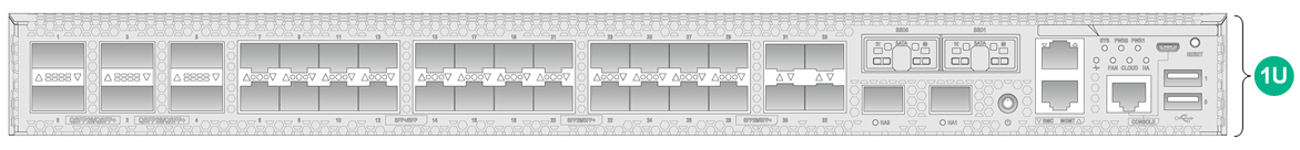
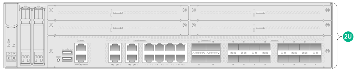
This document describes how to install 1U and 2U devices and their accessories. Rack Unit (RU or U) is a measurement unit used to indicate the height of a device.
· A 1U device indicates that the device is 1U high, as shown in Figure1-1.
· A 2U device indicates that the device is 2U high, as shown in Figure1-2.
Safety recommendations
To avoid bodily injury or device damage, read all safety recommendations carefully before installation. Note that the recommendations do not cover every possible hazardous condition.
Safety symbols
When reading this document, note the following symbols:
![]() WARNING means an alert that calls attention to important information that
if not understood or followed can result in personal injury.
WARNING means an alert that calls attention to important information that
if not understood or followed can result in personal injury.
![]() CAUTION means an alert that calls attention to important information that
if not understood or followed can result in data loss, data corruption, or
damage to hardware or software.
CAUTION means an alert that calls attention to important information that
if not understood or followed can result in data loss, data corruption, or
damage to hardware or software.
General safety recommendations
· Place the device in a spacious and flat area that is free from vibration or strong electromagnetic interference. Take adequate ESD prevention measures and anti-slip measures.
· Keep the chassis and installation tools away from walk areas.
· Do not place the device on an unstable case or desk. The device might be severely damaged in case of a fall.
· Keep the chassis clean and dust-free.
· Do not place the device in a wet area, and prevent liquid from flowing into the device chassis.
· Vertically align devices according to the sizes and packing symbols on the packages, and avoid any obvious tilts.
· Ensure good ventilation of the equipment room and keep the air inlet and outlet vents of the device free of obstruction.
· Make sure the power source voltage meets the requirements of the device.
· Use a screwdriver, rather than your fingers, to fasten screws.
· Do not wear loose clothing, jewelry (for example, necklace) or any other things that could get caught in the chassis when you install and maintain the device.
· Remove all packing materials and installation tools from the equipment room after the installation is complete.
Table1-2 Packing symbols
|
Symbol |
Description |
|
|
Stored with a maximum stack of n units. |
|
|
Transported and stored with the arrows up. |
|
|
Transported and stored with care. |
|
|
Transported and stored avoiding humidity, rains and wet floor. |


Electrical safety
· Carefully examine your work area for possible hazards such as moist floors, ungrounded power extension cables, and missing safety grounds.
· Locate the emergency power-off switch in the room before installation. Shut the power off at once in case accident occurs.
· Do not work alone when the device has power.
· Always verify that the power has been disconnected when you perform operations that require the device to be powered off.
Laser safety
|
|
WARNING! Disconnected optical fibers or transceiver modules might emit invisible laser light. Do not stare into beams or view directly with optical instruments when the device is operating. |
· Use the shutdown command in interface view at the CLI to shut down a fiber port before you remove the optical fiber from that fiber port.
· Insert a dust cap into any open optical fiber connector and a dust plug into any open fiber port or transceiver module port to protect them from contamination and ESD damage.
Handling safety
When you move the device, follow these guidelines:
· Move and unpack the device carefully to avoid device damage.
· Unpack the device at least half an hour and power on the device at least two hours after you move it from a place below 0°C (32°F) to the equipment room. This prevents condensation and even damage to the device.
· Use a safety hand truck when you move multiple devices.
· Before you move the device, remove all cables.
· For long-distance transportation, remove all the removable components, such as power supplies and interface modules, and package them separately, and install the filler panels supplied with the device. For short-distance transportation, make sure all the removable components are securely seated in the slots and the screws are fastened.
· When you move or lift the device chassis, support the bottom of the chassis, rather than holding any removable component.
· Make sure the accessories of the device are not lost or damaged during device moving.
Examining the installation site
The device can only be used indoors. To make sure the device operates correctly and to prolong its service lifetime, the installation site must meet the following requirements.
Weight support
Make sure the floor can support the total weight of the device and removable components (such as power supplies and interface modules).
For weights of a device and its removable components, see the hardware information and specifications for that device on the H3C official website at https://www.h3c.com/en/Support/Resource_Center/Technical_Documents/Security/.
Temperature and humidity
For correct operation and long service life of your device, maintain the temperature and humidity in the equipment room at acceptable ranges.
· Lasting high relative humidity can cause poor insulation, electricity leakage, mechanical property change of materials, and metal corrosion.
· Lasting low relative humidity can cause washer contraction and ESD and bring issues including loose screws and circuit failure.
· High temperature can accelerate the aging of insulation materials and significantly lower the reliability and lifespan of the device.
For the temperature and humidity requirements of a device, see the hardware information and specifications for that device on the H3C official website at https://www.h3c.com/en/Support/Resource_Center/Technical_Documents/Security/.
Cleanliness
Dust buildup on the chassis might result in electrostatic adsorption, which causes poor contact of metal components and contact points, especially when indoor relative humidity is low. In the worst case, electrostatic adsorption can cause communication failure. Table1-3 describes the dust concentration limits in the equipment room.
Table1-3 Dust concentration limits in the equipment room
|
Substance |
Concentration limit (particles/m3) |
|
Dust particles |
≤ 3 × 10⁴ (No visible dust on desk in three days) |
|
NOTE: Dust particle diameter ≥ 5 µm |
|
The equipment room must also meet strict limits on salts, acids, and sulfides to eliminate corrosion and premature aging of components, as shown in Table1-4.
Table1-4 Harmful gas limits in an equipment room
|
Gas |
Maximum concentration (mg/m3) |
|
SO2 |
0.2 |
|
H2S |
0.006 |
|
NH3 |
0.05 |
|
Cl2 |
0.01 |
|
NO2 |
0.04 |
Cooling system
The cooling method varies by device model. For the cooling method of a device, see the hardware information and specifications for that device on the H3C official website at https://www.h3c.com/en/Support/Resource_Center/Technical_Documents/Security/.
Cooling system for 1U devices
Plan the installation site for the device based on its airflow direction for adequate ventilation. Make sure the following requirements are met:
· Reserve a minimum of 100 mm (3.94 in) around the air inlet and outlet vents of the chassis.
· The installation site has a good cooling system.
· When you install the device in a standard 19-inch rack, ensure a distance of 1U (44.45 mm, or 1.75 in) between the chassis and other devices.
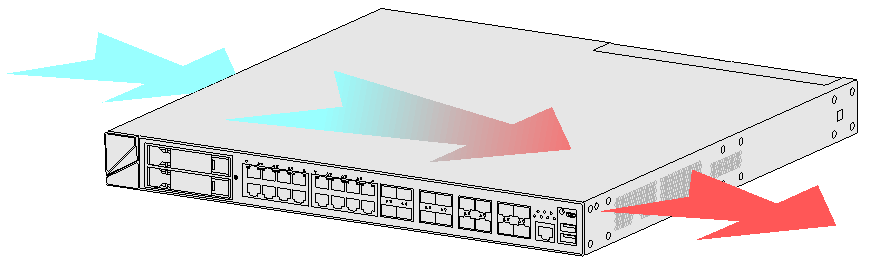
The cooling method varies by device model. 1U devices support the following cooling methods:
· Passive cooling.
· Front-to-rear airflow.
· Left-to-right airflow.
Figure1-3 Front-to-rear airflow
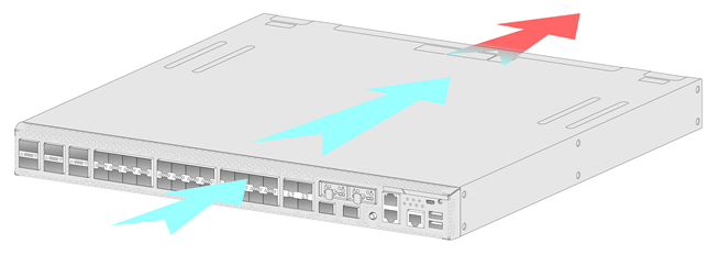
Figure1-4 Left-to-right airflow.
Cooling system for 2U devices
The device features a front-to-rear airflow design and can provide front-to-rear or rear-to-front airflow by using different fan trays. Plan the installation site for the device based on its airflow direction for adequate ventilation. Make sure the following requirements are met:
· The installation site has a good cooling system.
· Reserve about 100 mm (3.94 in) around the air inlet and outlet vents of the chassis.
You can use fan trays that blow air or draw air. As shown in Figure1-5 and Figure1-6, the fan tray blows air from the power supply side to the port side. The fan tray handle is blue. As shown in Figure1-7 and Figure1-8, the fan tray draws air from the port side to the power supply side. The fan tray handle is red.
Figure1-5 Airflow for a fan tray that blows air
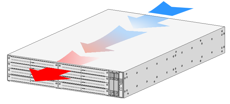
Figure1-6 Fan tray that blows air
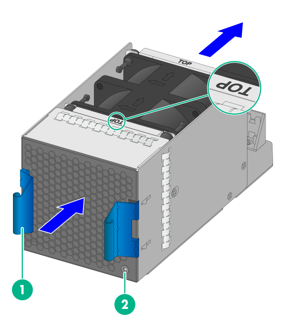
|
(1) Fan tray handle |
(2) Alarm LED |
Figure1-7 Airflow for a fan tray that draws air
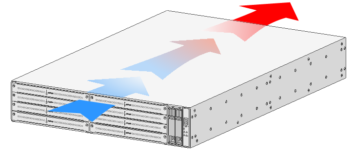
Figure1-8 Fan tray that draws air
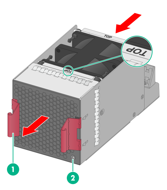
|
(1) Fan tray handle |
(2) Alarm LED |
ESD prevention
To prevent electrostatic discharge (ESD), follow these guidelines:
· Make sure the device, the workbench, and the rack are reliably grounded.
· Take dust-proof measures for the equipment room. For more information, see "Cleanliness."
· Maintain the humidity and temperature at an acceptable level. For more information, see "Temperature and humidity."
· To avoid possible electrical shocks or injury, wear ESD clothes, ESD gloves, and ESD wrist strap, and remove any jewelry or watches before you operate the device.
· Put the removed interface modules away on an ESD workbench, with the PCB upward, or put them in ESD bags for future use.
EMI
All electromagnetic interference (EMI) sources, from outside or inside of the device and application system, adversely affect the device in the following ways:
· A conduction pattern of capacitance coupling.
· Inductance coupling.
· Electromagnetic wave radiation.
· Common impedance (including the grounding system) coupling.
To prevent EMI, use the following guidelines:
· If AC power is used, use a single-phase three-wire power receptacle with protection earth (PE) to filter interference from the power grid.
· Keep the device far away from radio transmitting stations, radar stations, and high-frequency devices.
· Use electromagnetic shielding, for example, shielded interface cables, when necessary.
· To prevent signal ports from getting damaged by overvoltage or overcurrent caused by lightning strikes, route interface cables only indoors. If part of the network cable of an Ethernet port must be routed outdoors, connect a lightning arrester to the cable before you plug the cable into the port.
Lightning protection
To protect the device from lightning better, follow these guidelines:
· Make sure the grounding cable of the chassis is reliably grounded.
· Make sure the grounding terminal of the AC power receptacle is reliably grounded.
· If an AC power cord is routed from outdoors for connecting to the device, connect the power cord first to a power lightning arrester before connecting it to the power receptacle on the device.
· If a network cable is routed from outdoors for connecting to the device, connect the network cable first to a network port lightning arrester before connecting it to the port.
No network port lightning arrester or AC power lightning arrester is provided with the device. Prepare them as required.
For the technical specifications and installation and maintenance instructions for the lightning protectors, see the documents shipped with them.
Power supply
Verify that the power system at the installation site meets the requirements of the power supplies, including the input method and rated input voltage. For power supply specifications of a device, see the hardware information and specifications for that device on the H3C official website at https://www.h3c.com/en/Support/Resource_Center/Technical_Documents/Security/.
Installation tools
No installation tools are provided with the device. Prepare the installation tools yourself as required.
|
|
|
|
|
|
Flat-head screwdriver |
Phillips screwdriver |
Needle-nose pliers |
Marker |
|
|
|
|
|
|
Diagonal pliers |
ESD wrist strap |
Wire stripper |
Crimping tool |
Installation accessories
This document lists the installation accessories required for all devices. The required installation accessories vary by device model. For the installation accessories required by a device, see the hardware information and specifications for that device on the H3C official website at https://www.h3c.com/en/Support/Resource_Center/Technical_Documents/Security/.
|
|
|
|
|
|
4-hole narrow-gap mounting bracket |
4-hole mounting bracket |
2-hole extended mounting bracket |
2-hole mounting bracket |
|
|
|
|
|
|
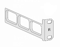
Rear mounting bracket |
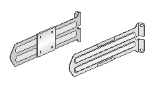
Slide rails and chassis rails |
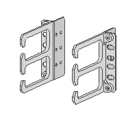
Mounting brackets with cable management brackets |
M4 shoulder screw |
|
|
|
|
|
|
Cage nut |
M4 mounting bracket screw |
M6 rack screw |
Rubber feet |
|
|
|
|
|
|
Grounding cable |
Power cord |
Power cord retainer clip |
Cable tie |


Pre-installation checklist
Table1-5 Pre-installation checklist
|
Item |
Requirements |
Result |
|
|
Installation site |
Ventilation |
· Ensure a minimum clearance of 100 mm (3.94 in) around the air inlet and outlet vents of the chassis. · A good ventilation system is available at the installation site. · If you install the device in a standard 19-inch rack, ensure a distance of 1U (44.45 mm, or 1.75 in) between the chassis and other devices. |
|
|
Temperature |
For more information, see the hardware information and specifications for the device. |
|
|
|
Humidity |
For more information, see the hardware information and specifications for the device. |
|
|
|
Cleanliness |
· Dust concentration ≤ 3 × 10⁴ particles/m3 · No dust on desk within three days |
|
|
|
ESD prevention |
· The device, rack, and workbench are reliably grounded. · The equipment room is dust-proof. · The humidity and temperature are at an acceptable level. · Wear an ESD wrist strap and make sure it makes good skin contact and is reliably grounded when installing removable components. · Touch only the edges, instead of electronic components when you install, remove, observe, or move a removed interface module. · Put the removed interface modules away on an ESD workbench, with the PCB upward, or put them in ESD bags for future use. |
|
|
|
EMI |
· Take effective measures to protect the power system from the power grid system. · Set up the device separately and away from the grounding facility of power distribution equipment and lightning protection system. · Keep the device far away from radio transmitting stations, radar stations, and high-frequency devices. · Use electromagnetic shielding when necessary. |
|
|
|
Lightning protection |
· The grounding cable of the chassis is reliably grounded. · The grounding terminal of the AC power receptacle is reliably grounded. · (Optional.) A power lightning arrester is installed. |
|
|
|
Electricity safety |
· Equip a UPS. · Locate the power switch in the equipment room so that the power can be immediately shut off when an accident occurs. |
|
|
|
Rack-mounting requirements |
· Make sure the rack has a good ventilation system. · The rack is sturdy enough to support the weight of the device and installation accessories. · The size of the rack is appropriate for the device. · The front and rear of the rack are a minimum of 0.8 m (2.62 ft) away from walls or other devices. |
|
|
|
Safety precautions |
· The device is far away from any moist area and heat source. · The emergency power-off switch in the equipment room is located. |
|
|
|
Tools and accessories |
· Installation accessories supplied with the device. · User-supplied tools. |
|
|
|
Reference |
· Documents shipped with the device. · Online documents. |
|
|
2 Installing the device
|
|
WARNING! Keep the tamper-proof seal on a mounting screw on the chassis cover intact, and if you want to open the chassis, contact H3C for permission. Otherwise, H3C shall not be liable for any consequence. |
The installation methods are similar for the device models. The following figures are for illustration only.
The installation method and accessories vary by device model. For more information about the installation method and accessories supported by a device, see the hardware information and specifications for that device on the H3C official website at https://www.h3c.com/en/Support/Resource_Center/Technical_Documents/Security/.
Installation flow
1. Start installation.
2. Mounting the device on a workbench
3. Mounting the device in a standard 19-inch rack
¡ For 1U devices, see "Mounting a 1U device in a standard 19-inch rack."
¡ For 2U devices, see "Mounting a 2U device in a standard 19-inch rack."
4. Grounding the device
¡ For 1U devices, see "Grounding a 1U device."
¡ For 2U devices, see "Grounding a 2U device."
7. Installing an interface module
10. Connecting Ethernet cables
12. Verifying the installation
Mounting the device on a workbench
If a standard 19-inch rack is not available, you can place the device on a workbench.
Restrictions and guidelines
· Only 1U devices can be mounted on a workbench.
· Verify that the workbench is sturdy and reliably grounded.
· Ensure good ventilation and a minimum clearance of 100 mm (3.94 in) around the chassis for heat dissipation.
· Avoid placing heavy objects on the device.
· For information about the support of a device for workbench mounting, see the hardware information and specifications for that device on the H3C official website at https://www.h3c.com/en/Support/Resource_Center/Technical_Documents/Security/.
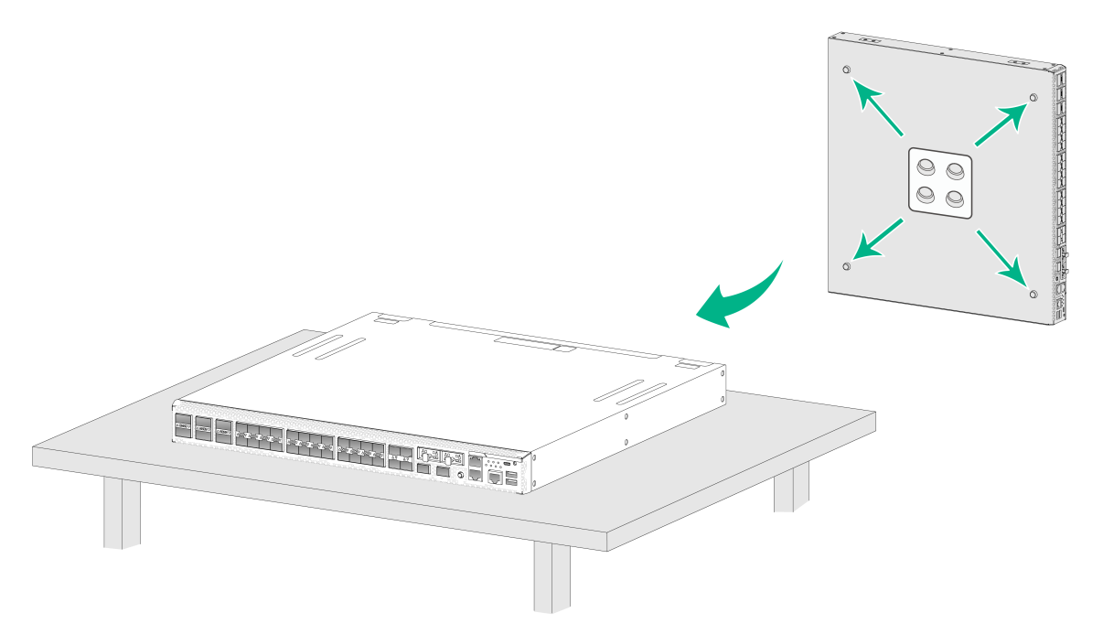
Mounting the device on a workbench
1. Unpack the device and accessories.
2. Place the device upside down on the workbench and clean the four round holes in the chassis bottom with dry cloth.
3. Attach the four rubber feet to the round holes in the chassis bottom.
4. Place the device with upside up on the workbench.
Figure2-1 Mounting the device on a workbench
Mounting a 1U device in a standard 19-inch rack
Restrictions and guidelines
· When you install the device in a standard 19-inch rack, follow these guidelines:
¡ Ensure a minimum clearance of 100 mm (3.94 in) around the air inlet and outlet vents of the chassis.
¡ Ensure a distance of 1U (44.45 mm, or 1.75 in) between the chassis and other devices.
· To avoid bodily injury or device damage, use a minimum of two persons to rack-mount the device.
Rack-mounting the device by using front and rear mounting brackets
This installation method is only applicable to devices that have front and rear mounting brackets.
To rack-mount the device by using front and rear mounting brackets:
1. Unpack the device and accessories.
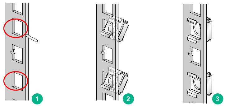
2. Mark the cage nut installation positions on the rack posts by using the mounting brackets.
Figure2-2 Installing cage nuts
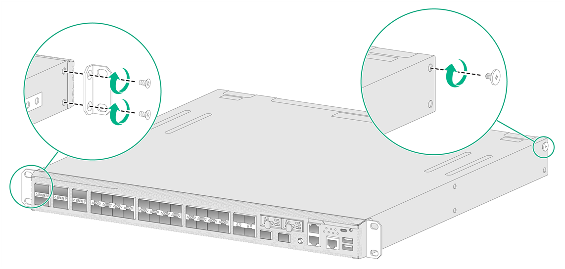
3. Attach the front mounting brackets to both sides of the device by using the provided M4 mounting bracket screws and attach the M4 shoulder screws to the device.
Figure2-3 Attaching front mounting brackets and shoulder screws to the device
4. Attach the rear mounting brackets to the rear rack posts.
|
|
CAUTION: To attach the rear mounting brackets to the rear rack posts with the wide flange outside the rack, ensure a distance greater than 153 mm (6.02 in) between the rear rack posts and the interior side of the rack door. If the distance does not meet the requirement, the rear mounting brackets will obstruct the normal closing of the rack door. |
For information about the distance between the front and rear rack posts when you attach rear mounting brackets to the rack, see the hardware information and specifications for the device on the H3C official website at https://www.h3c.com/en/Support/Resource_Center/Technical_Documents/Security/.
You can attach the rear mounting brackets to the rack with the wide flange inside or outside the rack. Table2-1 shows the distance between the front and rear rack posts when you attach rear mounting brackets to the rack.
Table2-1 Distance between the front and rear rack posts
|
Installation method |
Distance between the front and rear rack posts |
||
|
With the wide flange inside the rack |
405 to 569 mm (15.94 to 22.40 in) |
421 to 566 mm (16.57 to 22.28 in) |
531 to 696 mm (20.91 to 27.40 in) |
|
With the wide flange outside the rack |
247 to 411 mm (9.72 to 16.18 in) |
264 to 399 mm (10.39 to 15.71 in) |
373 to 538 mm (14.69 to 21.18 in) |
Figure2-4 Attaching the rear mounting brackets to the rear rack posts (with the wide flange inside the rack)
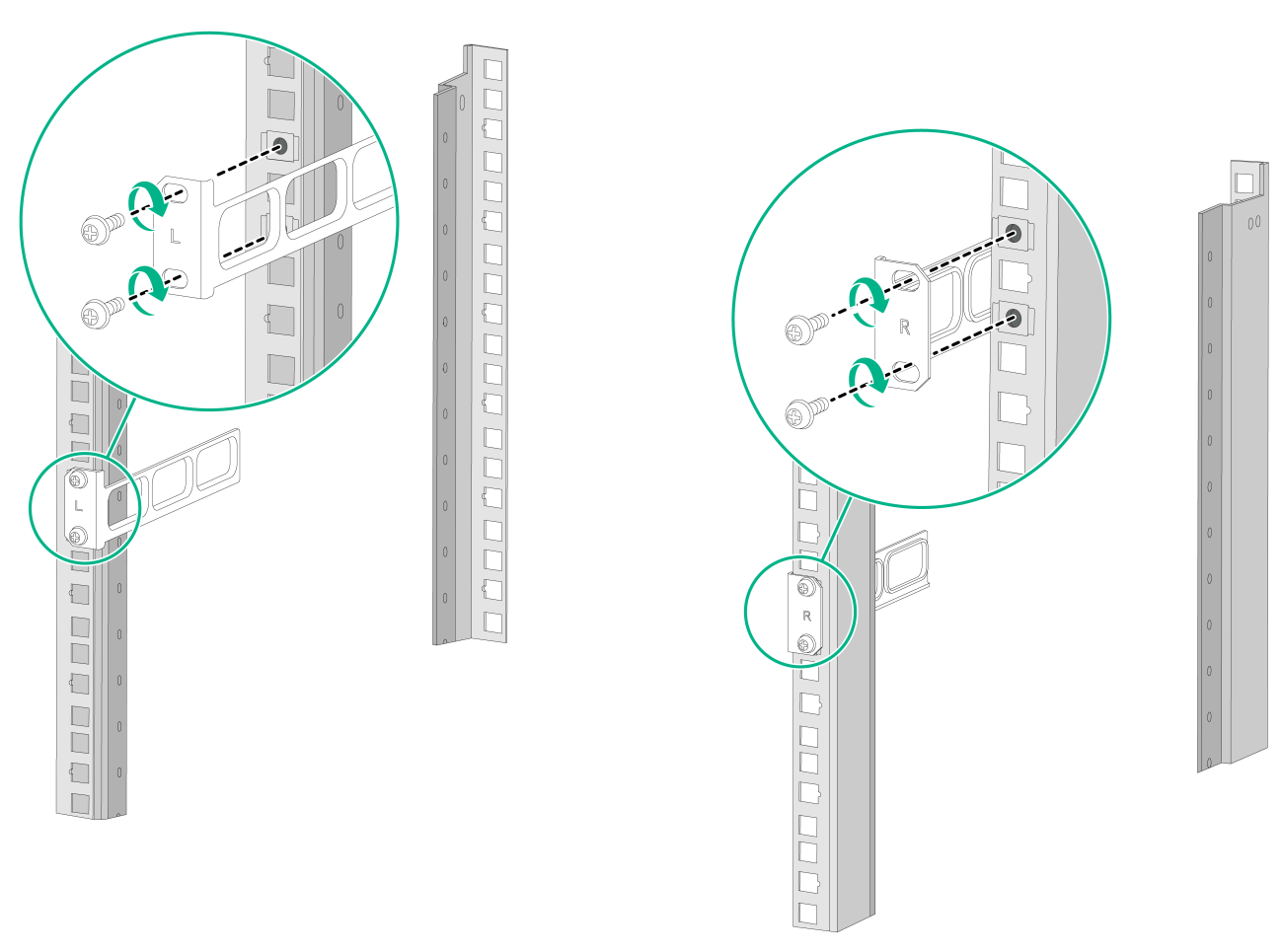
Figure2-5 Attaching the rear mounting brackets to the rear rack posts (with the wide flange outside the rack)

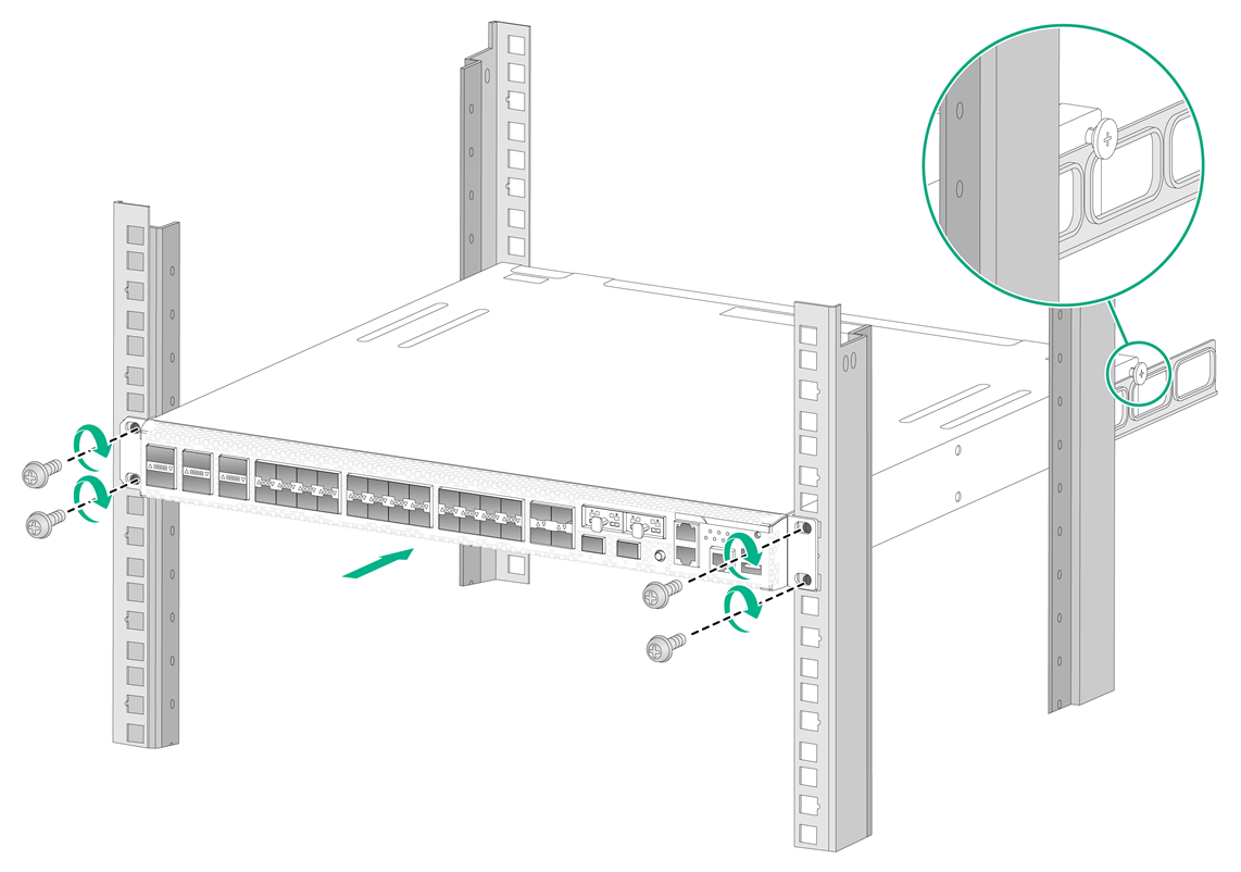
5. Mount the device in the rack. Use a Phillips screw to fasten M6 rack screws to secure the mounting brackets to the front rack posts and make sure the shoulder screws rest firmly on the upper edge of the rear mounting brackets.
Figure2-6 Mounting the device in the rack (with the wide flange of the rear mounting brackets inside the rack)
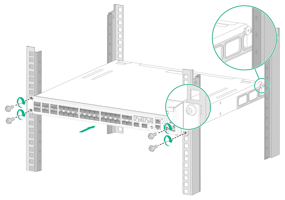
Figure2-7 Mounting the device in the rack (with the wide flange of the rear mounting brackets outside the rack)
Mounting a 2U device in a standard 19-inch rack
Restrictions and guidelines
· To mount the device in a standard 19-inch rack, make sure the rack meets the requirements described in Table2-2.
· To install multiple devices, ensure a distance of 1 RU (44.45 mm, or 1.75 in) between neighbor devices.
· The device is heavy. Install both mounting brackets and slide rails to support the weight of the device.
· To avoid bodily injury or device damage, use a minimum of two persons to rack-mount the device.
Table2-2 Recommended rack dimensions
|
Device model |
Rack requirements |
|
2U device |
· A minimum of 1000 mm (39.37 ft) in depth (recommended). · A minimum of 100 mm (3.94 in) from the front rack posts to the front door. · A minimum of 760 mm (29.92 in) from the front rack posts to the rear door. · 518 to 923 mm (20.39 to 36.34 in) from the front rack posts to the rear rack posts. |
Rack-mounting the device
The device provides multiple chassis rail installation positions on its side panels. Attach the chassis rails to the correct positions based on the rack depth. For device stability, make sure the front ends of the slide rails reach out of the chassis rails.
To rack-mount the device:
1. Unpack the device and accessories.
2. Wear an ESD wrist strap and make sure the stack is sturdy and reliably grounded.
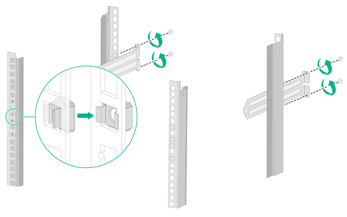
3. Use front mounting brackets to mark the cage nut installation positions on the front rack posts. Use slide rails to mark the cage nut installation positions on the rear rack posts. Make sure the lowest cage nuts on the front and rear rack posts are at the same level.
4. Install cages nuts at the marked installation positions and attach the slide rails to the rear rack posts.
Figure2-8 Installing cage nuts and slide rails
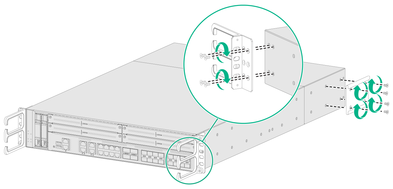
5. Use the provided M4 mounting bracket screws to attach the front mounting brackets and chassis rails to both sides of the device.
Figure2-9 Attaching front mounting brackets to the device
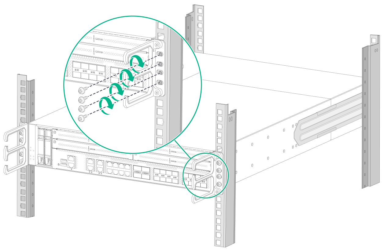
6. Supporting the bottom of the device, align the chassis rails with the slide rails and slide the slide rails into the chassis rails until the mounting brackets engage the front rack posts.
7. Use a Phillips screwdriver to fasten the M6 rack screws to secure the mounting brackets to the front rack posts.
Figure2-10 Mounting the device in the rack
Grounding a 1U device
|
|
WARNING! · Correctly connecting the grounding cable is crucial to lightning protection and EMI protection. To install and use the device, first connect the grounding cable for the device reliably. · Connect the grounding cable to the grounding strip in the equipment room. Do not connect it to a fire main or lightning rod. |
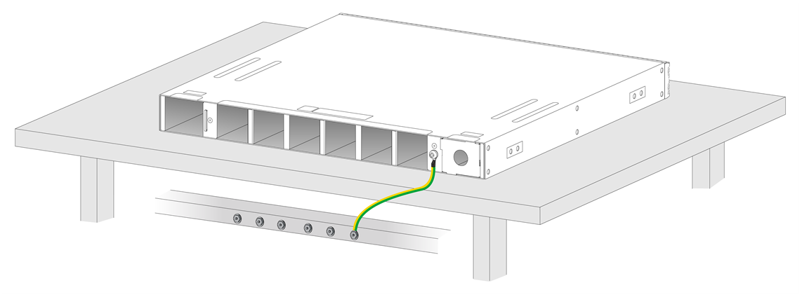
Grounding the device by using a grounding strip
If a grounding strip is available at the installation site, you can connect the grounding cable of the device to the grounding strip.
To ground the device by using a grounding strip:
1. Remove the grounding screw from the device chassis.
2. Use the grounding screw to attach the ring terminal of the grounding cable to the grounding screw hole, and then fasten the screw.
3. Remove the hex nut from a grounding terminal on the grounding strip.
4. Use the needle-nose pliers to bend a hook at the other end of the grounding cable. Attach the hook to the grounding post, and secure the hook with the nut.
Figure2-11 Grounding the device by using a grounding strip
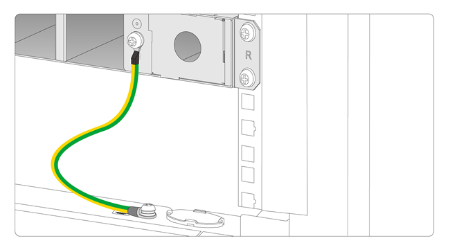
Grounding the device by using the grounding terminal on the rack
1. Make sure the rack is reliably grounded.
2. Remove the grounding screw from the device chassis.
3. Use the grounding screw to attach the ring terminal of the yellow-green grounding cable to the grounding screw hole. Use a Phillips screwdriver to fasten the screw.
4. Remove the nut from a grounding post on the grounding terminal.
5. Use the needle-nose pliers to bend a hook at the other end of the grounding cable. Attach the hook to the grounding post, and secure the hook with the nut.
Figure2-12 Grounding the device by using the grounding terminal on the rack
Grounding a 2U device
|
|
WARNING! · Correctly connecting the grounding cable is crucial to lightning protection and EMI protection. To install and use the device, first connect the grounding cable for the device reliably. · Connect the grounding cable to the grounding strip in the equipment room. Do not connect it to a fire main or lightning rod. |
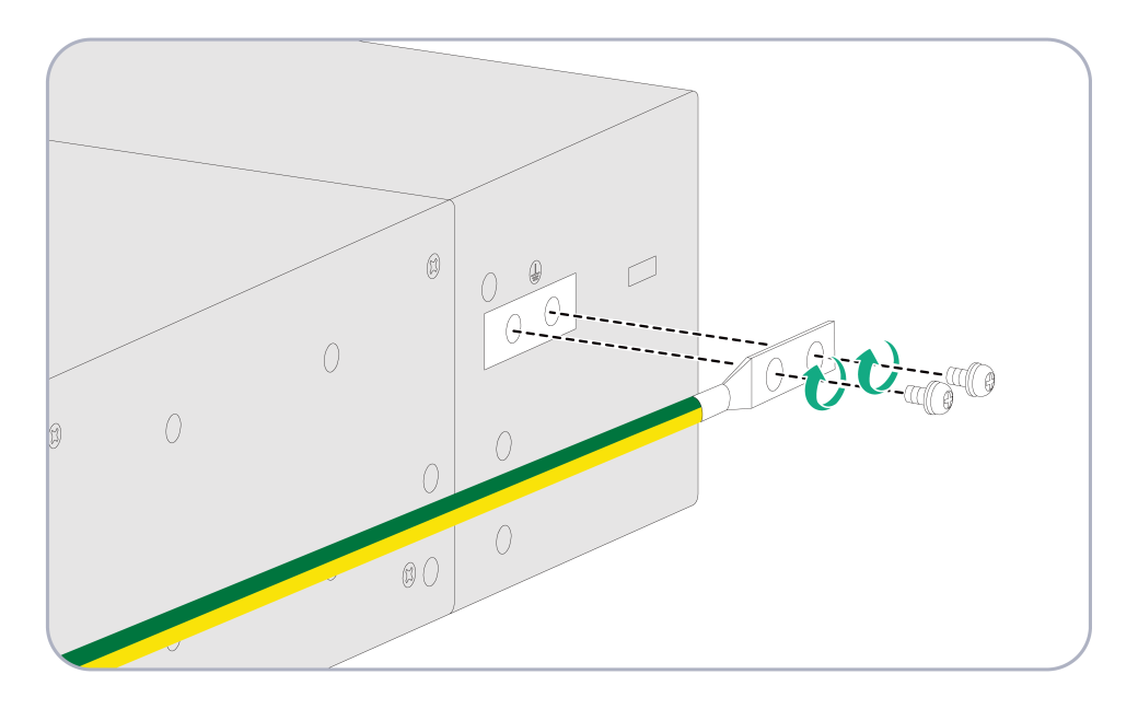
|
|
IMPORTANT: Before mounting the device in a rack, connect the grounding cable for it. Use the grounding point near the front panel. If you use the grounding point near the rear panel, you cannot attach the chassis rails to the device. |
The device provides a primary grounding point near the front panel and an auxiliary grounding point. The following uses the primary grounding point as an example.
To ground the device:
1. Use grounding screws to attach the two-hole lug of the grounding cable to the grounding screw holes, and then fasten the screws.
2. Connect the ring terminal at the other end to the grounding strip of the rack.
Figure2-13 Connecting the grounding cable to the primary grounding point
Installing a power supply
|
|
CAUTION: · Before installing a power supply, make sure the power supply is powered off and the grounding cable is correctly connected for the device. · Do not install AC and DC power supplies on the same device. |
For information about the power supplies available for a device, see the hardware information and specifications for that device on the H3C official website at https://www.h3c.com/en/Support/Resource_Center/Technical_Documents/Security/.
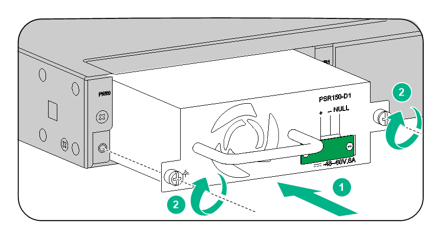
Installing a PSR150-A1/PSR150-D1 power supply
The installation methods are similar for the PSR150-A1 and PSR150-D1 power supplies.
To install a PSR150-A1 or PSR150-D1 power supply:
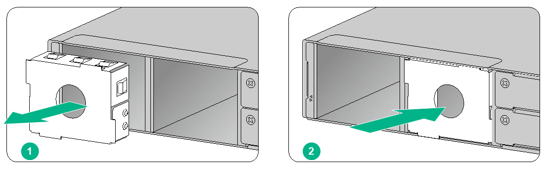
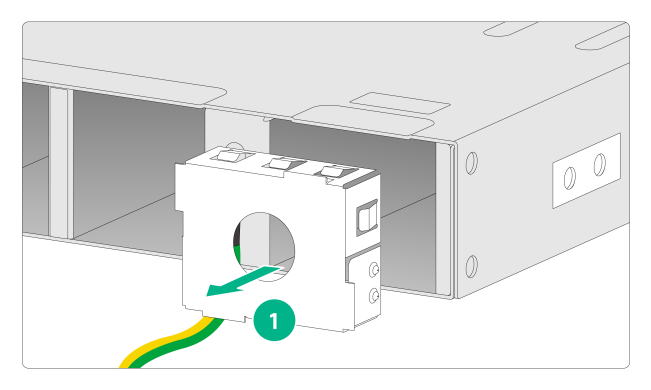
1. Remove the filler panel from the target power supply slot.
Figure2-14 Removing the power supply filler panel
2. Orient the power supply with its handle at the left. Holding the power supply handle with one hand and supporting the power supply bottom with the other, slide the power supply slowly into the slot along the guide rails.
3. Use a Phillips screwdriver to fasten the captive screws on the power supply.
Figure2-15 Installing an AC power supply

Figure2-16 Installing a DC power supply
Installing a PSR250-12A1/PSR450-12AHD/PSR450-12D power supply
The installation methods are similar for the PSR250-12A1, PSR450-12AHD, and PSR450-12D power supplies. The following uses the PSR250-12A1 power supply as an example.
To install a PSR250-12A1 power supply:
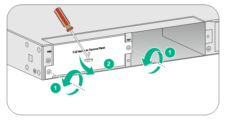
1. Remove the filler panel (if any) from the target power supply slot.
The device came with power supply slot PWR1 empty and power supply slot PWR0 installed with a filler panel.
Figure2-17 Removing the power supply filler panel
2. Orient the power supply with its handle at the right. Holding the power supply handle with one hand and supporting the power supply bottom with the other, slide the power supply slowly into the slot along the guide rails.
Figure2-18 Installing a power supply
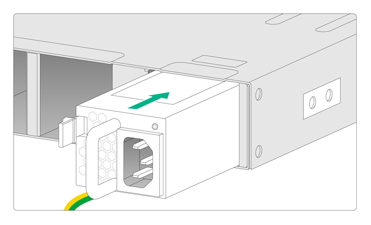
Installing a PSR650B-12A1/PSR650B-12D1/PSR650B-12AHD-F power supply
The installation methods are similar for the PSR650B-12A1, PSR650B-12D1, and PSR650B-12AHD-F power supplies. The following uses the PSR650B-12A1 power supply as an example.
To install a PSR650B-12A1 power supply:
1. Remove the filler panel from the target power supply slot.
Figure2-19 Removing the power supply filler panel
2. Orient the power supply with its power receptacle at the right. Holding the power supply handle with one hand and supporting the power supply bottom with the other, slide the power supply slowly into the slot along the guide rails.
Figure2-20 Installing a power supply
Installing a fan tray
|
|
CAUTION: · The device supports hot swapping of fan trays. · Before installing a fan tray, make sure the airflow direction marked on the fan tray meets the ventilation requirement of the installation site. · The device came with both fan tray slots empty. To ensure good ventilation, you must install two fan trays of the same model before powering on the device. · The device will power off automatically at startup if it does not have any fan trays installed. You must disconnect the power cords from the device and then restart the device after installing fan trays on it. · To prevent damage to the fan tray or the backplane connectors, insert the fan tray gently. If you encounter a hard resistance while inserting the fan tray, pull out the fan tray and insert it again. · If a fan tray fails on an operating device, replace the fan tray immediately and keep the failed fan tray in position before replacement. |
No fan trays are provided with the device. Prepare them yourself as required.
For information about the fan trays available for a device, see the hardware information and specifications for that device on the H3C official website at https://www.h3c.com/en/Support/Resource_Center/Technical_Documents/Security/.
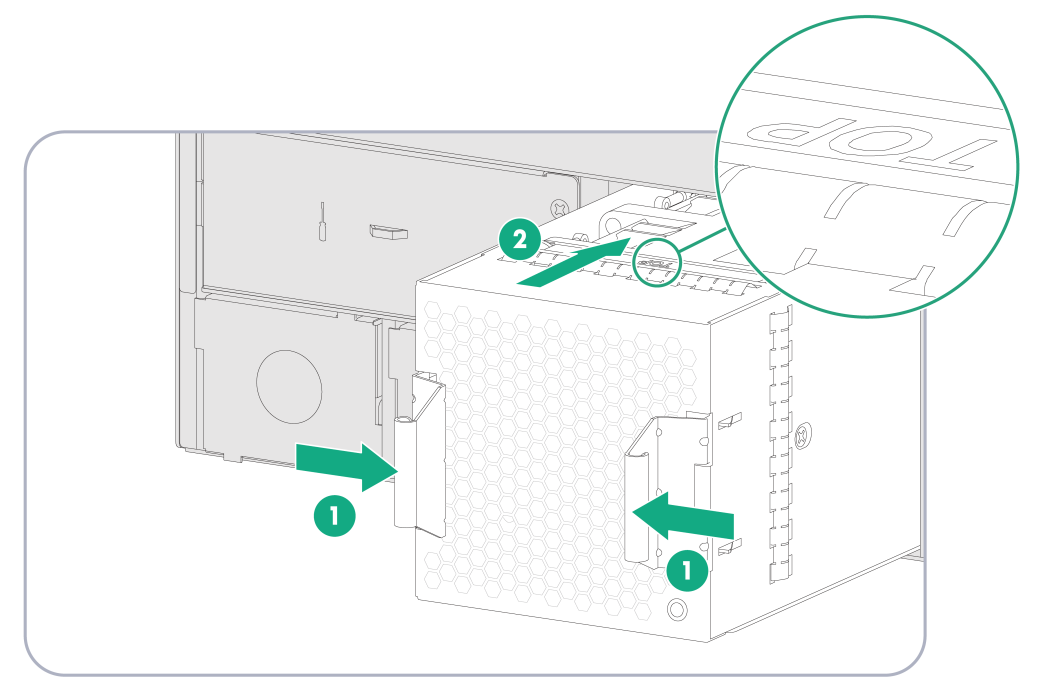
The installation methods are similar for the fan trays. This section uses the LSWM1BFANSCB fan tray as an example.
To install a fan tray:
1. Unpack the fan tray and verify that the fan tray model is correct.
2. Orient the fan tray with the "TOP" mark on the top. Holding the fan tray handles with one hand and supporting the fan tray bottom with the other, insert the fan tray into the slot along the guide rails until it has a firm contact with the backplane.
Figure2-21 Installing a fan tray
Installing an interface module
|
|
CAUTION: · Do not hot swap interface modules. · No interface modules are provided with the device. Prepare them yourself as required. · As a best practice, use the upper interface module slots when you install two or more interface modules. If you have installed an interface module in a lower slot, you must press down the ejector levers of the interface module while inserting it into an upper slot. |
For information about the interface modules available for a device, see the hardware information and specifications for that device on the H3C official website at https://www.h3c.com/en/Support/Resource_Center/Technical_Documents/Security/.
The installation methods are similar for the interface modules. The following uses an NSQM1GP4FBA interface module as an example.
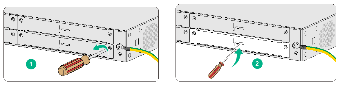
To install an NSQM1GP4FBA interface module:
1. Face the rear panel of the device.
2. Use a Phillips screwdriver to loosen the screws on the filler panel, and then remove the filler panel.
Keep the filler panel for future use.
Figure2-22 Removing the filler panel
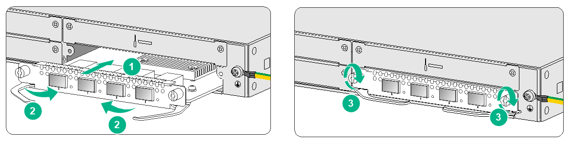
3. Open the ejector levers on the interface module and slide the interface module slowly into the slot along the guide rails.
4. Close the ejector levers until they engage the panel tightly and the interface module seats into the slot securely.
5. Use a Phillips screwdriver to fasten the captive screws on the interface module.
Figure2-23 Installing an interface module
Installing a high-density interface module
|
|
CAUTION: · Do not hot swap high-density interface modules. · No high-density interface modules are provided with the device. Prepare them yourself as required. · Only E9900P19 and later versions support high-density interface modules. |
For information about the high-density interface modules available for a device, see the hardware information and specifications for that device on the H3C official website at https://www.h3c.com/en/Support/Resource_Center/Technical_Documents/Security/.
The installation methods are similar for the high-density interface modules. This section uses the NS-FPIM-CQG4TG16GT16AL high-density interface module as an example.
To install an NS-FPIM-CQG4TG16GT16AL interface module:
1. Face the front panel of the device.
2. Use a Phillips screwdriver to loosen the screws on the filler panels, and then remove the filler panels.
Keep the filler panels secure for future use.
Figure2-24 Removing a filler panel
3. Loosen the slide rail mounting screws and remove the three slide rails from the chassis.
4. Slide the high-density interface module slowly into the slot along the guide rails until the interface module is fully seated in the slot.
5. Use a Phillips screwdriver to fasten the captive screws on the high-density interface module.
Figure2-25 Installing a high-density interface module

Installing a drive
|
|
CAUTION: · Do not hot swap drives. · Hold a drive by its sides. Do not touch drive components and do not squeeze, shake, or strike the drive. · To avoid ESD damage, wear an ESD wrist strap when installing a drive. · To prevent dust or ESD damage, install a filler panel in any empty drive slot. |
|
|
IMPORTANT: · The device does not come with any drives and cannot recognize drives from other vendors. Purchase drives from H3C as required. · Before using a drive, execute the fdisk and format commands from the CLI to partition and format the drive. |
For information about the drives available for a device, see the hardware information and specifications for that device on the H3C official website at https://www.h3c.com/en/Support/Resource_Center/Technical_Documents/Security/.
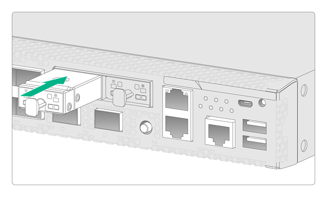
Installing an M.2 drive
1. Remove the filler panel from the target drive slot.
2. Push the drive slowly into the slot along the guide rails.
Figure2-26 Installing an M.2 drive
Installing a SATA drive
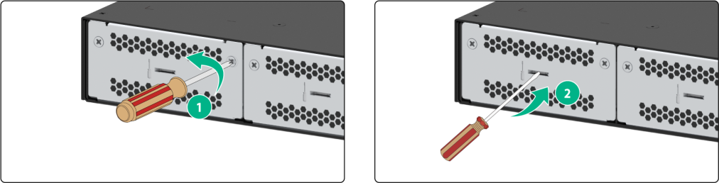
1. Remove the filler panel from the target drive slot.
2. Press the button on the drive panel to release the locking lever.
3. Holding the locking lever, gently push the drive into the slot along the guide rails.
4. Close the locking lever.
Figure2-27 Installing a SATA drive
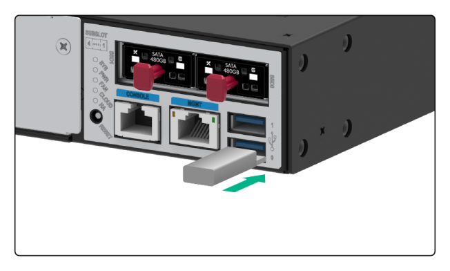
Installing a USB drive
|
|
IMPORTANT: · No USB drives are provided with the device. Prepare them yourself as required. · USB drives are plug and play. To use a USB drive, connect it to a USB port on the device. |
For the support of a device for USB drives, see the hardware information and specifications for that device on the H3C official website at https://www.h3c.com/en/Support/Resource_Center/Technical_Documents/Security/.
The installation methods are similar for USB 2.0 and USB 3.0 drives.
To install a USB drive:
1. Face the front panel of the device.
2. Correctly orient the USB drive, and then push the USB drive slowly into the slot until the USB drive seats in the slot. To avoid slot damage, do not use excessive force when you install the USB drive.
Figure2-28 Installing a USB drive
Connecting Ethernet cables
Connecting an Ethernet copper port
You can use either a straight-through or a crossover network cable to connect an Ethernet copper port.
To connect an Ethernet copper port:
1. Connect one end of the Ethernet cable to an Ethernet copper port on the device, and the other end to an Ethernet copper port on the peer device.
2. Examine whether the LEDs of the Ethernet port are normal.
|
|
NOTE: · After connecting the device to the network, you can use the ping or tracert command to verify network connectivity. For more information about the commands, see the command reference for the device. · For more information about Ethernet twisted pair cables, see "Cables." |
Connecting an Ethernet fiber port
|
|
WARNING! Disconnected optical fibers or transceiver modules might emit invisible laser light. Do not stare into beams or view directly with optical instruments when the device is operating. |
|
|
CAUTION: · Never bend or curve a fiber excessively. The bend radius of a fiber must be not less than 100 mm (3.94 in). · Keep the fiber end clean. · Make sure the fiber connector matches the transceiver module. · Before connecting a fiber, make sure the optical receive power does not exceed the transceiver module's upper threshold. If the threshold is exceeded, the transceiver module might be damaged. |
The device supports GE SFP copper transceiver modules, GE SFP optical transceiver modules, 10GE SFP+ transceiver modules, 40GE QSFP+ transceiver modules, and 100GE QSFP+ transceiver modules.
For information about the transceiver modules available for a device, see the hardware information and specifications for that device on the H3C official website at https://www.h3c.com/en/Support/Resource_Center/Technical_Documents/Security/.
No transceiver modules are provided with the device. As a best practice, use H3C transceiver modules for the device.
Figure2-29 GE SFP copper transceiver module
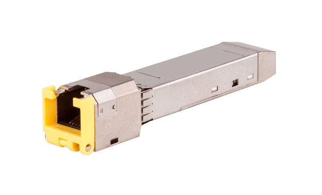
Figure2-30 GE SFP optical transceiver module
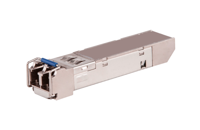
Figure2-31 10GE SFP+ transceiver module
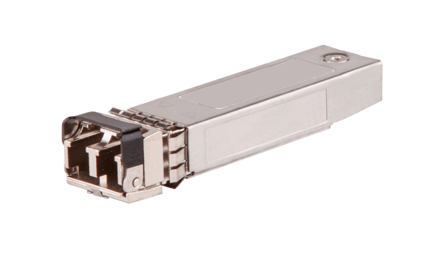
Figure2-32 SFP28 transceiver module
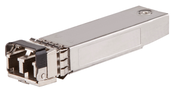
Figure2-33 QSFP28 transceiver module (MPO connector)
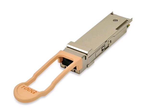
Figure2-34 QSFP28 transceiver module (LC connector)

To connect an Ethernet fiber port:
1. Remove the dust plug from the fiber port.
2. Pull the bail latch on the transceiver module upwards. Skip this step if the bail latch is plastic.
3. Take the transceiver module by its two sides and align it with the fiber port.
4. Push the transceiver module gently into the port until it is firmly seated in the fiber port.
5. Remove the dust plug and dust cap from the transceiver module and fiber connector, respectively. Then, clean the fiber end.
6. Connect the optical fiber to the transceiver module.
¡ LC connector—Align the connector with the transceiver module and push it into the transceiver module slightly until it clicks into place.
¡ MPO connector—Orient the connector with the white spot on it facing right. Insert the MPO connector horizontally into the transceiver module. Push the MPO fiber connector into the transceiver module slightly until it clicks into place.
7. Use cable ties to bind optical fibers every 150 mm (5.91 in).
8. Label optical fibers according to the cable labeling specifications.
Figure2-35 Installing a transceiver module and optical fiber (LC connector)

Figure2-36 Installing a transceiver module and optical fiber (MPO connector)
Connecting power cords
|
|
CAUTION: Make sure the grounding cable of the device is correctly connected and the power source is powered off before connecting the power cord. |
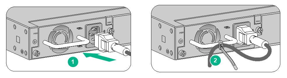
Connecting an AC power cord
1. Attach the hooks of the power cord retainer clip into the holes next to the AC power receptacle, and pull the power cord retainer clip leftwards.
2. Connect one end of the AC power cord to the AC power receptacle on the device. Use the provided cable tie or power cord retainer clip to secure the power cord, as shown in Figure2-37 and Figure2-38.
3. Connect the other end of the power cord to an AC power source.
Figure2-37 Securing the power cord by using a power cord retainer clip
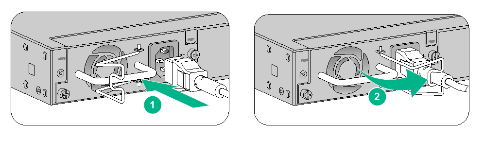
Figure2-38 Securing the power cord by using a cable tie
Connecting a DC power cord
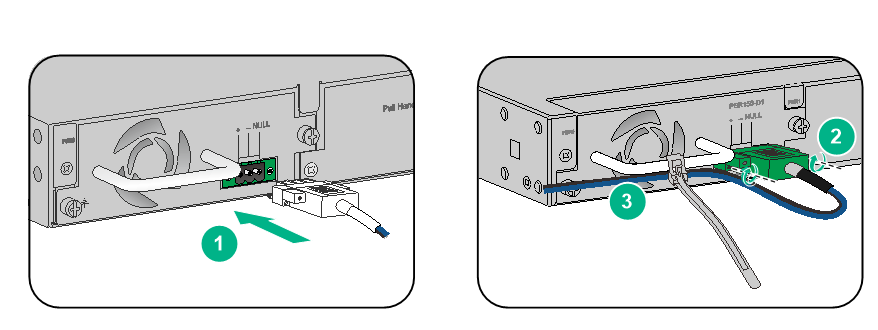
1. Correctly orient the DC power cord plug with the power receptacle on the power supply, and then insert the plug into the receptacle.
2. Use a cable tie to secure the DC power cord to the power supply handle.
3. Connect the other end of the power cord to a DC power source.
Figure2-39 Securing a DC power cord
Connecting an HVDC power cord
For information about connecting the power cord for an HVDC power supply, see "Connecting an AC power cord."
Verifying the installation
After you complete the installation, verify the following information:
· There is enough space for heat dissipation around the device, and the device is securely installed.
· All screws are fastened tightly.
· The power source meets the power specifications of the device.
· The grounding cable and power cords are securely connected.
3 Logging in to the device
Powering on the device
Checking before power-on
|
|
CAUTION: Locate the emergency power-off switch in the room before power-on so you can quickly shut power off when an accident occurs. |
Before powering on the device, verify the following information:
· The power cords and grounding cable are correctly connected.
· The power source meets the power specifications of the device.
· The console cable is correctly connected, the terminal or PC used for configuration has started, and the configuration parameters have been correctly set.
· The interface modules (if any) are correctly installed.
Powering on the device
Switch on the power source of the device.
Checking after power-on
After powering on the device, verify that:
1. The LEDs on the front panel indicate that the device is operating correctly. For more information about LEDs on a device, see the hardware information and specifications for that device on the H3C official website at https://www.h3c.com/en/Support/Resource_Center/Technical_Documents/Security/.
2. The fan blades are rotating and air is exhausted from the air outlet vents.
3. The configuration terminal displays the following information:
The command output varies by software version used by the device.
System is starting...
Press Ctrl+D to access BASIC-BOOTWARE MENU...
Press Ctrl+T to start heavy memory test
Booting Normal Extended BootWare
The Extended BootWare is self-decompressing......Done.
****************************************************************************
* *
* H3C BootWare, Version 1.01 *
* *
****************************************************************************
Copyright (c) 2004-2021 New H3C Technologies Co., Ltd.
Compiled Date : Aug 2 2021
Memory Type : DDR4 SDRAM
Memory Size : 8152MB
Memory Speed : 1037MHz
flash Size : 3728MB
CPLD 1 Version : 0.0
CPLD 2 Version : 1.0
PCB 1 Version : Ver.A
PCB 2 Version : Ver.A
Press Ctrl+B to access EXTENDED-BOOTWARE MENU...
Loading the main image files...
Loading file flash:/main-CMW710-SYSTEM-XXXX.bin...Done.
Loading file flash:/main-CMW710-SECESCAN-XXXX.bin...Done.
Loading file flash:/main-CMW710-BOOT-XXXX.bin...Done.
Image file flash:/main-CMW710-BOOT-XXXX.bin is self-decompressing....
............................................................................
..................................Done.
System image is starting...
Cryptographic algorithms tests passed.
Line con0 is available.
Press ENTER to get started...
...
Press ENTER to access user view of the device.
|
|
NOTE: To access the EXTENDED-BOOTWARE menu, press Ctrl+B within 4 seconds at the prompt "Press Ctrl+B to access EXTENDED-BOOTWARE MENU." If you do not press Ctrl+B at the prompt, the system starts to read and decompress program files. To enter the EXTENDED-BOOTWARE menu afterwards, you must reboot the device. |
Login methods
|
|
CAUTION: To ensure device security, change the default login password or create a new administrator account and delete the default one after logging in to the device by using the default account. |
The device supports the following types of login methods:
· Web login—The device is provided with factory default Web login information. You can log in to the Web interface of the device by using the default Web login information.
· CLI login from the console port or micro USB console port—By connecting the console port or micro USB console port of the device to a configuration terminal, you can log in to the CLI of the device. At the CLI, you can configure settings for login through Telnet or SSH.
· Remote login through Telnet/SSH—You can access and manage the device remotely through Telnet or SSH.
Logging in from the Web interface
The default Web interface login information is as follows:
· Username—admin
· Password—admin
· IP address of the management Ethernet port—192.168.0.1/24
For detailed configuration, see the device nameplate or the hardware information and specifications for the device on the H3C official website at https://www.h3c.com/en/Support/Resource_Center/Technical_Documents/Security/.
You can log in to the Web interface by using the default login information. This section uses management Ethernet port IP address 192.168.0.1/24 as an example.
To log in to the device from the Web interface by using the default account:
1. Use an Ethernet cable to connect a PC to the management Ethernet port on the device.
2. Configure an IP address in subnet 192.168.0.0/24 for the PC. Make sure the PC and the device can reach each other.
The PC must use a different IP address than the management Ethernet port.
3. Start a browser, enter 192.168.0.1 in the address bar, and then press Enter.
4. Enter the default username admin and password admin, and then click Login.
5. Modify the login information.
At the first login from the Web interface, change the password as required in the pop-up window, and then click OK.
Logging in from the console port
Console cables
As shown in Table3-1, two types of console cables can be used for connecting the device to a configuration terminal.
Table3-1 Connection methods and console cables
|
Connection method |
Console cable type |
Configuration terminal-side connector |
Device-side connector |
|
Using the console port for connection |
DB9-to-RJ45 console cable |
DB-9 female connector |
RJ-45 |
|
USB-to-RJ45 console cable |
USB port |
RJ-45 |
No console cables are provided with the device. Prepare them yourself as required.
The signal pinout for the RJ-45 connector of a console cable varies by vendor. To avoid abnormal configuration terminal display, use a console cable provided by H3C. For more information, see Table3-2. To prepare a serial console cable yourself, make sure the signal pinout for the RJ-45 connector is the same as that shown in Table7-1.
|
Console cable type |
Console cable view |
Product code for the recommended H3C console cable |
|
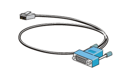
DB9-to-RJ45 console cable |
|
04042967 |
|
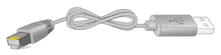
USB-to-RJ45 console cable |
|
0404A1EE |
Connecting a DB9-to-RJ45 console cable
|
|
CAUTION: · Identify the mark on the console port and make sure you are connecting to the correct port. · The serial ports on PCs do not support hot swapping. To connect a PC to an operating device, first connect the PC end. To disconnect a PC from an operating device, first disconnect the device end. |
To connect a DB9-to-RJ45 console cable:
1. Plug the DB-9 female connector of the console cable to the serial port on the PC.
2. Connect the RJ-45 connector of the console cable to the console port on the device.
Connecting a USB-to-RJ45 console cable
|
|
IMPORTANT: · To use a USB-to-RJ45 console cable to connect the device to a configuration terminal, first download and install the USB-to-RJ45 console driver on the configuration terminal, and then connect the USB-to-RJ45 console cable to the configuration terminal. To download the USB-to-RJ45 console driver, access the H3C official website or scan the QR code on the cable package. · If you have connected a USB-to-RJ45 console cable to the configuration terminal before driver installation, you must reconnect the USB-to-RJ45 console cable to the configuration terminal. |
The following installs the driver on the Windows system. To install the driver on other operating systems, see the installation guide in the driver compression package named by the corresponding operating system.
To connect the device to a configuration terminal by using a USB-to-RJ45 console cable:
1. Click the following link, or copy it to the address bar on your browser and download the USB-to-RJ45 console driver.
http://www.h3c.com/en/home/USB_to_RJ45_Console/
2. View the TXT file Read me in the Windows folder to check whether the Windows system of the configuration terminal supports the driver.
3. If the Windows system supports the driver, install PL23XX-M_LogoDriver_Setup_v200_20190815.exe.
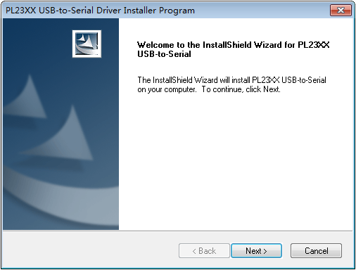
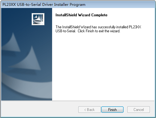
4. Click Next on the welcome page of the driver installation wizard.
Figure3-1 Driver installation wizard
5. Click Finish after the driver installation is completed.
Figure3-2 Finishing the driver installation
6. Connect the standard USB connector of the cable to the USB port on the configuration terminal.
7. Connect the RJ-45 connector of the cable to the console port on the device.
Setting terminal parameters
To configure and manage the device through the console port, you must run a terminal emulator program, such as HyperTerminal or PuTTY, on your configuration terminal. You can use the emulator program to connect a network device, a Telnet site, or an SSH site. For more information about the terminal emulator programs, see the user guides for these programs.
The first time you log in to the device, you can log in to the CLI of the device from the console port. The default console port login information is as follows:
· Authentication method—scheme
· Username—admin
· Password—admin
Configure the parameters as follows:
· Baud rate—9600 (for illustration only).
· Data bits—8.
· Stop bits—1.
· Parity—None.
· Flow control—None.
|
|
NOTE: · Typically, the default baud rate is 9600 bps. However, the default baud rate is 115200 bps in some cases. Configure the baud rate as required. · For information about the default baud rate of ports on a device, see the hardware information and technical specifications for that device on the H3C official website at https://www.h3c.com/en/Support/Resource_Center/Technical_Documents/Security/. |
Powering on the device
During the startup process, you can access Boot ROM menus to perform tasks such as software upgrade and file management. The Boot ROM interface and menu options vary by software version. For more information about Boot ROM menu options, see the software-matching release notes for the device.
Logging in from the micro USB console port
Connecting the console cable
Figure3-3 Micro USB console cable

|
|
NOTE: · For information about the support of a device for login from the micro USB console port, see the hardware information and specifications for that device on the H3C official website at https://www.h3c.com/en/Support/Resource_Center/Technical_Documents/Security/. · To use a micro USB console cable to connect the device to a configuration terminal, first download and install the USB console driver on the configuration terminal and then connect the micro USB console cable to the configuration terminal (PC). · For information about the micro USB console cable specifications, see "Cables." |
To connect the device to a configuration terminal by using a micro USB console cable:
1. Connect the standard USB connector of the cable to the USB port on the PC.
2. Click the following link, or copy it to the address bar on the browser to log in to download and install the USB console driver on the configuration terminal.
http://www.h3c.com/en/home/USB_Console/
3. Run Installer to preinstall the driver. After the preinstallation finishes, the system pops up a dialog box to indicate a successful preinstallation.
4. Connect the micro USB connector to the micro USB console port on the device. The system installs the driver automatically.
Setting terminal parameters
For more information, see "Logging in from the console port."
Powering on the device
During the startup process, you can access Boot ROM menus to perform tasks such as software upgrade and file management. The Boot ROM interface and menu options vary by software version. For more information about Boot ROM menu options, see the software-matching release notes for the device.
Logging in through Telnet
1. Log in to the device from the console port. Execute the telnet server enable command in system view to enable Telnet.
2. Enter VTY user line view, and configure the authentication mode, user role, and common properties. By default, the authentication mode is scheme, the username is admin, and the password is admin.
3. The device is shipped with the default IP address of the management Ethernet port. Assign an IP address to the PC's network port and make sure the PC and device can reach each other.
4. Run the Telnet client on the PC and enter the default login information.
For more information about how to log in to the device through Telnet, see the configuration guides and command references that come with your device.
4 Hardware replacement
|
|
CAUTION: Wear an ESD wrist strap or ESD gloves for hardware maintenance. They are not provided with the device. Prepare them yourself. |
Replacing a power supply
|
|
CAUTION: Before you replace a power supply, turn off the circuit breaker and remove the power cord. |
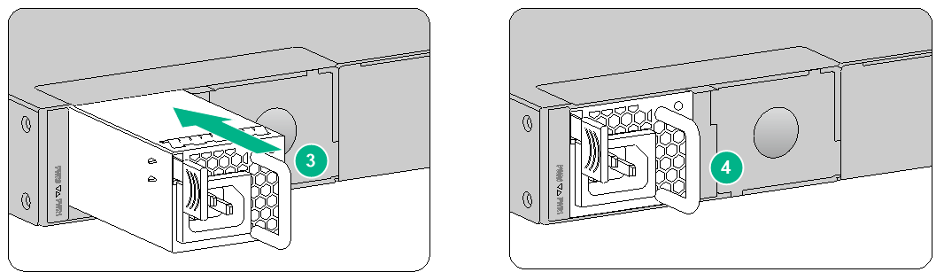
Replacing a PSR150-A1/PSR150-D1 power supply
The removal methods are the same for the AC and DC power supplies. This section uses a DC power supply as an example.
To replace a DC power supply:
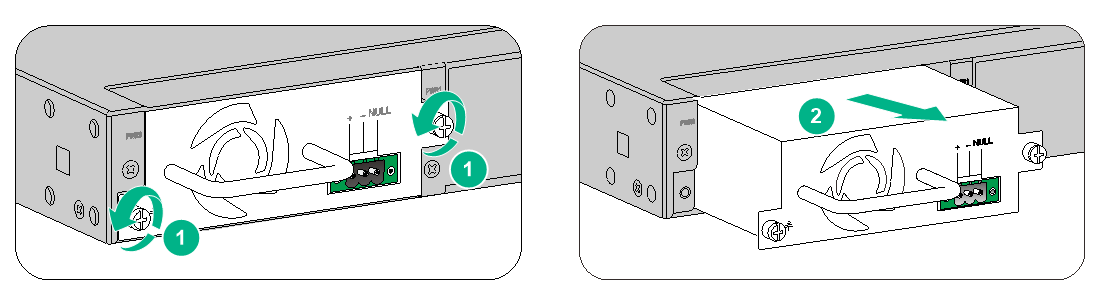
1. Use a Phillips screwdriver to loosen the captive screws on the power supply.
2. Holding the power supply handle with one hand and supporting the power supply bottom with the other, pull the power supply slowly out of the slot along the guide rails.
Figure4-1 Removing a power supply
3. Put the removed power supply on a workbench or in an antistatic bag.
4. Install a new power supply. For the installation procedure, see "Installing a PSR150-A1/PSR150-D1 power supply."
Replacing a PSR250-12A1/PSR450-12AHD/PSR450-12D power supply
The removal methods are the same for the AC and DC power supplies. This section uses an AC power supply as an example.
To replace an AC power supply:
1. Face the rear panel of the device.
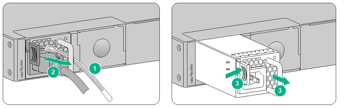
2. Loosen the releasable cable tie and remove the power cord.
3. Holding the power supply handle with one hand, press the latch towards the handle and pull the power supply part way out of the slot. Supporting the power supply bottom with the other hand, slowly pull the power supply out of the slot.
Figure4-2 Removing a power supply
4. Put the removed power supply on a workbench or in an antistatic bag.
5. Install a new power supply. For the installation procedure, see "Installing a PSR250-12A1/PSR450-12AHD/PSR450-12D power supply."
Install a filler panel in the slot if you are not to install a new power supply.
Replacing a PSR650B-12A1/PSR650B-12D1/PSR650B-12AHD-F power supply
The removal methods are the same for the AC and DC power supplies. This section uses an AC power supply as an example.
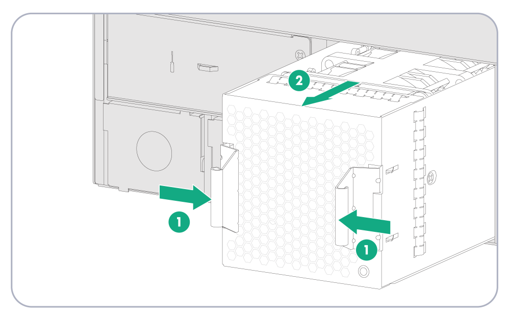
To replace an AC power supply:
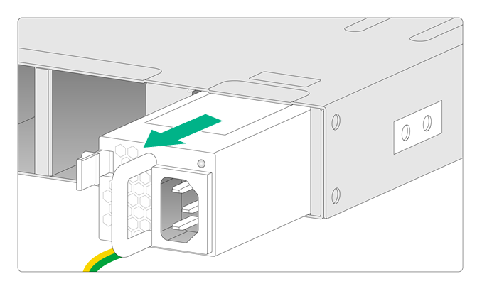
1. Loosen the cable tie and remove the power cord.
2. Holding the power supply handle with one hand, press the latch towards the handle and pull the power supply part way out of the slot. Supporting the power supply bottom with the other hand, slowly pull the power supply out of the slot.
Figure4-3 Removing a power supply
3. Put the removed power supply on a workbench or in an antistatic bag.
4. Install a new power supply. For the installation procedure, see "Installing a PSR650B-12A1/PSR650B-12D1/PSR650B-12AHD-F power supply."
Install a filler panel in the slot if you are not to install a new power supply.
Replacing an interface module
|
|
CAUTION: · Do not hot swap interface modules. Power off the device before replacing an interface module. · A high-density interface module occupies subslots 1 to 4. To replace a high-density interface module with an interface module, remove the high-density interface module, install the removed three slide rails, and then install the interface module. |
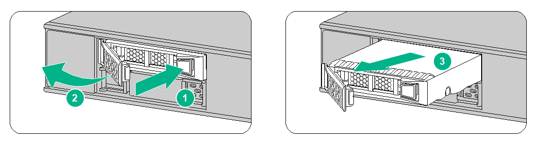
The replacement methods are similar for interface modules with ejector levers. This section uses the NSQM1GP4FBA interface module as an example.
To replace an NSQM1GP4FBA interface module:
1. Power off the device.
2. Use a Phillips screwdriver to loosen the captive screws on the interface module.
3. Holding the two ejector levers of the interface module, open the ejector levers, and then pull the interface module part way out of the slot along the guide rails. Supporting the bottom of the interface module with one hand, use the other hand to gently pull the interface module out of the slot.
4. Put the removed interface module on an antistatic workbench or in an antistatic bag with the PCB facing upward.
5. Install a new interface module. For the installation procedure, see "Installing an interface module."
Install a filler panel in the slot if you are not to install a new interface module.
Figure4-4 Removing an interface module
Replacing a high-density interface module
|
|
CAUTION: · Do not hot swap high-density interface modules. Power off the device before you replace a high-density interface module. · A high-density interface module occupies subslots 1 to 4. To replace an interface module with a high-density interface module, remove the interface module, remove the slide rail mounting screws and three slide rails, and then install the high-density interface module. |
The replacement methods are similar for the high-density interface modules with ejector levers. This section uses the NS-FPIM-CQG4TG16GT16AL interface module as an example.
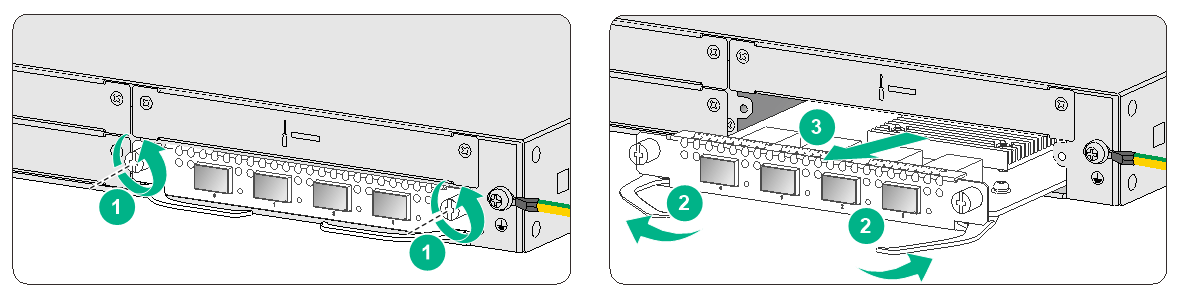
To replace an NS-FPIM-CQG4TG16GT16AL interface module:
1. Power off the device.
2. Use a Phillips screwdriver to loosen the captive screws on the high-density interface module.
3. Holding the two ejector levers of the high-density interface module, open the ejector levers, and then pull the high-density interface module part way out of the slot along the guide rails. Supporting the bottom of the high-density interface module with one hand, use the other hand to gently pull the high-density interface module out of the slot.
4. Put the removed high-density interface module on an antistatic workbench or in an antistatic bag with the PCB facing upward.
5. Install a new high-density interface module. For the installation procedure, see "Installing a high-density interface module."
Install the three slide rails and filler panels if you are not to install a new high-density interface module.
Replacing a fan tray
|
|
WARNING! · Ensure electricity safety if you replace a fan tray on an operating device. · To avoid bodily injury, do not touch rotating fans. · To prevent an unbalanced fan from causing loud noise, do not touch the fan blades or rotation axis, even if the fan is not rotating. |
To replace a fan tray:
1. Holding the fan tray handle with one hand, pull the fan tray part way out of the slot. Supporting the fan tray bottom with the other hand, pull the fan tray slowly out of the slot along the guide rails.
Figure4-5 Removing a fan tray
2. Put the removed fan tray on a workbench or in an antistatic bag.
3. Install a new fan tray. For the installation procedure, see "Installing a fan tray."
Install a filler panel in the slot if you are not to install a new fan tray.
Replacing a drive
|
|
CAUTION: · Do not hot swap drives. · To avoid ESD damage, wear an ESD wrist strap when replacing a drive. · To avoid damage caused by build-up dust, install a filler panel in a drive slot if you are not to install a drive in it. · To avoid storage medium damage, execute the umount command from the CLI to unmount all partitions before removing a drive. |
Replacing an M.2 drive
1. Log in to the Web interface. Click the unmount button on the storage settings page.
2. Pull the drive slowly out of the slot along the guide rails.
3. Install the drive filler panel.
Figure4-6 Replacing an M.2 drive
4. Install a new M.2 drive. For the installation procedure, see "Installing an M.2 drive."
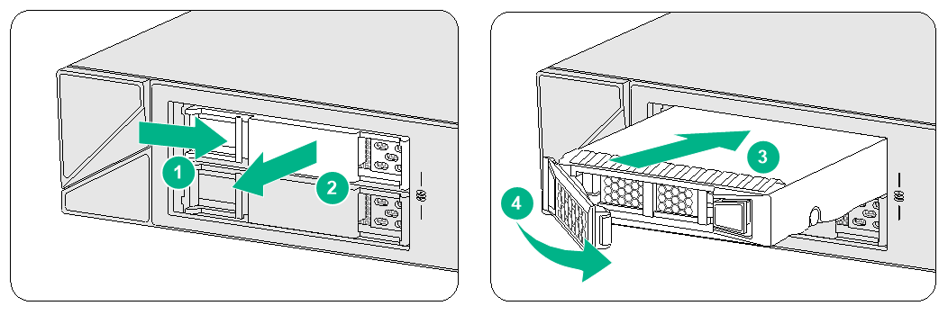
Replacing a SATA drive
1. Log in to the Web interface. Click the unmount button on the storage settings page.
2. Press the button on the drive panel to release the locking lever.
3. Hold the locking lever and pull the drive out of the slot.
Figure4-7 Replacing a SATA drive
4. Install a new SATA drive. For the installation procedure, see "Installing a SATA drive."
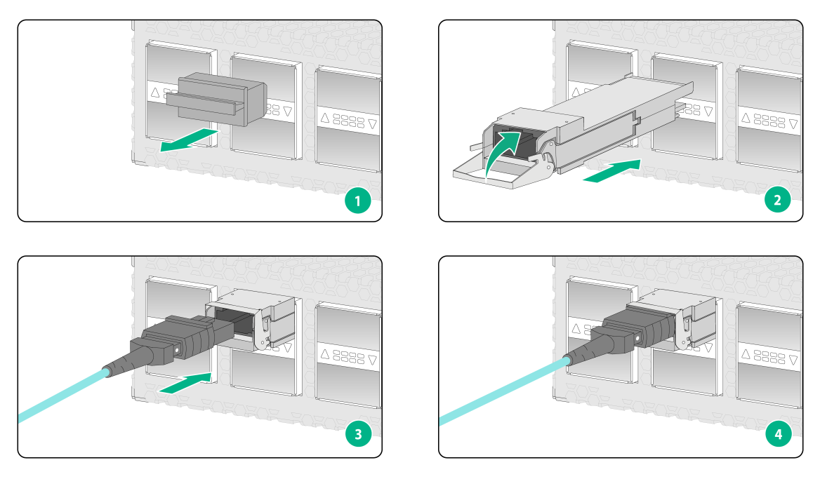
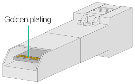
Replacing a transceiver module
|
|
WARNING! Disconnected optical fibers or transceiver modules might emit invisible laser light. Do not stare into beams or view directly with optical instruments when the device is operating. |
Do not touch the golden plating on a transceiver module during the replacement process.
Figure4-8 Golden plating
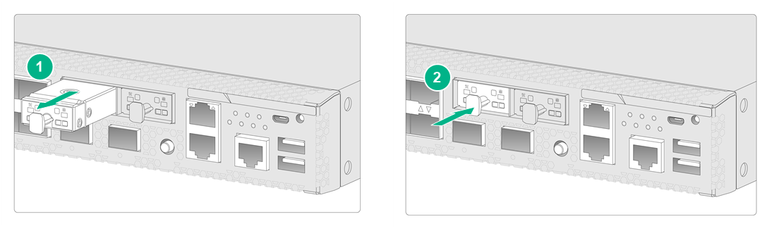
To replace a transceiver module:
1. Use the shutdown command in interface view at the CLI to shut down the port.
2. Remove the optical fiber from the transceiver module.
¡ To remove the optical fibers with an LC connector, press the clips on the connector to pull the LC connector out of the port, as shown in Figure4-9.
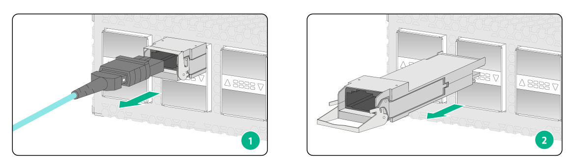
¡ To remove the optical fiber with an MPO connector, hold the front end of the MPO connector to pull the connector out of the port, as shown in Figure4-10.
3. Pull down the bail latch on the transceiver module. Skip this step if the bail latch is plastic.
4. Hold the bail latch to pull the transceiver module slowly out of the port.
If the interface module is densely populated with transceiver modules, use tweezers to pull the transceiver module out.
5. Attach dust plugs to the removed transceiver module, and put it into the package.
6. Install a new transceiver module in the port. For the installation procedure, see "Connecting an Ethernet fiber port."
If you are not to install a new transceiver module in the slot, install a dust cap.
Figure4-9 Removing a transceiver module (LC connector)
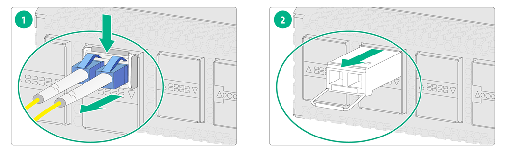
Figure4-10 Removing a transceiver module (MPO connector)
5 Hardware management and maintenance
The command output depends on the software version used by your device. For more information about the commands used in this chapter, see the software-matching configuration guides and command references for the device.
Displaying detailed information about the device
Use the display device verbose command to display detailed information, including the running status and hardware version, about the device and its interface modules.
<Sysname> display device verbose
Slot 1 SubSlot 0 info:
Status : Normal
Type : XXXX
PCB 1 Ver : VER.A
Software Ver : XXXX
CPU Ver : 1.0
CPLD_A : 128.0
CPLD_B : 129.0
CFCard Num : 0
Displaying software and hardware version information for the device
Use the display version command to display software and hardware version information for the device.
<Sysname> display version
H3C Comware Software, Version 7.1.064, XXXX
Copyright (c) 2004-2021 New H3C Technologies Co., Ltd. All rights reserved.
H3C SecPath XXXX uptime is 0 weeks, 0 days, 5 hours, 21 minutes
Last reboot reason: User reboot
Boot image: flash:/main-CMW710-BOOT-XXXX.bin
Boot image version: 7.1.064, Alpha XXXX
Compiled Jul 14 2021 15:00:00
System image: flash:/main-CMW710-SYSTEM-XXXX.bin
System image version: 7.1.064, Alpha XXXX
Compiled Jul 14 2021 15:00:00
Feature image(s) list:
flash:/main-CMW710-SECESCAN-XXXX.bin, version: 7.1.064
Compiled Jul 14 2021 15:00:00
SLOT 1
CPU type: Multi-core CPU
DDR4 SDRAM Memory: 8192M bytes
FLASH: 3728M bytes
CPLD_A Version:128.0
CPLD_B Version:129.0
Release Version:XXXX
Basic BootWare Version:1.01
Extend BootWare Version:1.01
BuckleBoard Version:Ver.A
BaseBoard Version:Ver.A
BackBoard Version:Ver.A
HDD BackBoard Version:Ver.A
[SUBCARD 0] NSQ1F1G2MSPUOTXA(Hardware)Ver.A, (Driver)1.0, (Cpld)128.0
Displaying electrical label information for the device
Use the display device manuinfo command to display the electrical label information for the device.
<Sysname> display device manuinfo
Slot 1 CPU 0:
DEVICE_NAME : XXXX
DEVICE_SERIAL_NUMBER : XXXX
MAC_ADDRESS : 0868-8DBC-3B73
MANUFACTURING_DATE : NONE
VENDOR_NAME : NONE
Fan 0:
The operation is not supported on the specified fan.
Fan 1:
The operation is not supported on the specified fan.
Fan 2:
The operation is not supported on the specified fan.
Fan 3:
The operation is not supported on the specified fan.
Power 0:
DEVICE_NAME : PSR150-A1
DEVICE_SERIAL_NUMBER : 210231A1U0H16B005100
MAC_ADDRESS : NONE
MANUFACTURING_DATE : NONE
VENDOR_NAME : H3C
Table5-1 Output description
|
Field |
Description |
|
DEVICE_NAME |
Device name. |
|
DEVICE_SERIAL_NUMBER |
Device serial number. |
|
MAC_ADDRESS |
MAC address of the device. |
|
MANUFACTURING_DATE |
Manufacturing date of the device. |
|
VENDOR_NAME |
Vendor name. |
Displaying the CPU usage of the device
Use the display cpu-usage command to display the CPU usage of the device.
<Sysname> display cpu-usage
Slot 1 CPU 0 CPU usage:
3% in last 5 seconds
3% in last 1 minute
3% in last 5 minutes
Table5-2 Output description
|
Field |
Description |
|
Slot 1 CPU 0 CPU usage |
CPU 0 usage information for the interface module in slot 1. |
|
3% in last 5 seconds |
Average CPU usage in the last 5 seconds. (After the device boots, the device calculates and records the average CPU usage at the interval of 5 seconds.) |
|
3% in last 1 minute |
Average CPU usage in the last minute. (After the device boots, the device calculates and records the average CPU usage at the interval of 1 minute.) |
|
3% in last 5 minutes |
Average CPU usage in the last 5 minutes. (After the device boots, the device calculates and records the average CPU usage at the interval of 5 minutes.) |
Displaying the operational status of power supplies
Use the display power command to display the operational status of power supplies.
<Sysname> display power
Power 0 Status: Normal
Power 1 Status: Absent
Table5-3 Output description
|
Field |
Description |
|
Power |
Number of the power supply. |
|
Status |
Power supply state: · Normal—The power supply is operating correctly. · Absent—The power supply is not in position. · Abnormal—The power supply has failed. |
Displaying the memory usage of the device
Use the display memory command to display the memory information of the device.
<Sysname> display memory
Memory statistics are measured in KB:
Slot 1:
Total Used Free Shared Buffers Cached FreeRatio
Mem: 8212672 4655360 3557312 0 17152 549952 43.9%
-/+ Buffers/Cache: 4088256 4124416
Swap: 0 0 0
Table5-4 Output description
|
Field |
Description |
|
Mem |
Memory usage information. |
|
Total |
Total size of the physical memory space that can be allocated. The memory space is virtually divided into two parts. Part 1 is used for kernel codes, kernel management, and ISSU functions. Part 2 can be allocated and used for such tasks as running service modules and storing files. The size of part 2 equals the total size minus the size of part 1. |
|
Used |
Used physical memory. |
|
Free |
Free physical memory. |
|
Shared |
Physical memory shared by processes. |
|
Buffers |
Physical memory used for buffers. |
|
Cached |
Physical memory used for caches. |
|
FreeRatio |
Free memory ratio. |
|
-/+ Buffers/cache |
-/+ Buffers/Cache:used = Mem:Used – Mem:Buffers – Mem:Cached, which indicates the physical memory used by applications. -/+ Buffers/Cache:free = Mem:Free + Mem:Buffers + Mem:Cached, which indicates the physical memory available for applications. |
|
Swap |
Swap memory. |
Displaying temperature information for the device
Use the display environment command to display the temperature information of the device.
<Sysname> display environment
System Temperature information (degree centigrade):
--------------------------------------------------------------------------------
---------
Slot Sensor Temperature LowerLimit Warning-UpperLimit Alarm-UpperLimit Shutdown-UpperLimit
1 inflow 1 31 0 47 52
60
1 outflow 1 39 0 68 80
88
1 hotspot 1 47 0 63 68
75
1 hotspot 2 54 0 84 97
102
Table5-5 Output description
|
Field |
Description |
|
Sensor |
Temperature sensor: · inflow—Air inlet vent temperature sensor. · outflow—Air outlet vent temperature sensor. · hotspot—Hotspot temperature sensor. |
|
Temperature |
Current temperature. |
|
LowerLimit |
Low temperature alarm threshold. |
|
Warning-UpperLimit |
Warning-level high temperature alarm threshold. |
|
Alarm-UpperLimit |
Alarm-level high temperature alarm threshold. |
|
Shutdown-UpperLimit |
Shutdown-level high temperature alarm threshold. The device automatically powers off when the temperature exceeds this threshold. |
Displaying the operational statistics of the device
When you perform routine maintenance or the system fails, you might need to view the operational information of each functional module for locating failures. Typically, you must run display commands one by one. To collect more information one time, you can execute the display diagnostic-information command in any view to display or save the operational statistics of multiple functional modules of the device.
· Save the operational statistics of each functional module of the device:
<Sysname> display diagnostic-information
Save or display diagnostic information (Y=save, N=display)? [Y/N]:y
Please input the file name(*.tar.gz)[sda0:/diag_H3C_20210807-155002.tar.gz]:
Diagnostic information is outputting to sda0:/diag_H3C_20210807-155002.tar.gz.
Please wait...
Save successfully.
To view the diag.gz file:
a. Execute the tar extract archive-file diag.tar.gz command in user view to decompress the file.
b. Execute the gunzip diag.gz command.
c. Execute the more diag command.
d. Press Page Up and Page Down.
· Display the operational statistics for each functional module of the device:
<Sysname> display diagnostic-information
Save or display diagnostic information (Y=save, N=display)? [Y/N]:n
===============================================
===============display clock===============
15:54:53 UTC Fri 08/07/2021
=================================================
===============display version===============
H3C Comware Software, Version 7.1.064, Alpha 8860P02
Copyright (c) 2004-2021 New H3C Technologies Co., Ltd. All rights reserved.
H3C SecPath XXXX uptime is 1 week, 2 days, 2 hours, 9 minutes
...
Displaying transceiver module information
Identifying transceiver modules
To identify transceiver modules, you can use the following command to view the key parameters of the transceiver modules, including transceiver module type, connector type, central wavelength of the laser sent, transmission distance, and vendor name or name of the vendor who customizes the transceiver modules.
To display transceiver module information:
|
Task |
Command |
Remarks |
|
Display key parameters of the transceiver module in a specific interface. |
display transceiver interface [ interface-type interface-number ] |
Available for all transceiver modules. |
Troubleshooting transceiver modules
The system outputs alarm information for you to locate and troubleshoot faults of transceiver modules.
To display the alarm information or fault detection parameters of a transceiver module:
|
Task |
Command |
Remarks |
|
Display the current alarm information of the transceiver module in a specific interface. |
display transceiver alarm interface [ interface-type interface-number ] |
Available for all transceiver modules. |
Rebooting the device
|
|
CAUTION: · If the main system software image file does not exist, do not use the reboot command to reboot the device. Specify the main system software image file first, and then reboot the device. · The precision of the rebooting timer is 1 minute. 1 minute before the rebooting time, the device prompts "REBOOT IN ONE MINUTE" and reboots in 1 minute. · If you are performing file operations when the device is to be rebooted, the system does not execute the reboot command for security. |
To reboot a device, use one of the following methods:
· Use the reboot command to reboot the device immediately.
· Enable the scheduled reboot function at the CLI. You can set a time at which the device can automatically reboot, or set a delay so that the device can automatically reboot within the delay.
· Power on the device after powering it off, which is also called hard reboot or cold start. As a best practice, do not use this method because it might cause data loss or hardware damage.
To reboot the device immediately:
|
Task |
Command |
Remarks |
|
Reboot the device immediately. |
reboot |
Required. Available in user view. |
To enable the scheduled reboot function:
|
Task |
Command |
Remarks |
|
Enable the scheduled reboot function and specify the reboot time and date. |
scheduler reboot at |
Use either method. The scheduled reboot function is disabled by default. Available in user view. |
|
Enable the scheduled reboot function and specify the reboot delay time. |
scheduler reboot delay |
6 Troubleshooting
Power supply failure
Symptom
The device cannot be powered on, and the power supply status LED on the front panel is off.
Solution
To solve the issue:
1. Power off the device.
2. Verify that the power supply is as required by the device.
3. Verify that the power cords of the device are firmly connected.
4. Verify that the power cords are not damaged.
5. If the issue persists, contact your local sales agent.
Configuration terminal display issue
Symptom
The configuration terminal displays nothing or garbled text when the device is powered on.
Solution
To solve the issue:
1. Verify that the power supply system is operating correctly.
2. Verify that the console cable or micro USB console cable is correctly connected.
3. Verify that the console cable or micro USB console cable is connected to the serial port configured on the configuration terminal.
4. Verify that the configuration terminal parameters are configured correctly. For example:
¡ Baud rate—9600.
¡ Data bits—8.
¡ Parity—None.
¡ Stop bits—1.
¡ Flow control—None.
¡ Terminal emulation—VT100.
5. Verify that the console cable or micro USB console cable is in good condition.
6. If the issue persists, contact your local sales agent.
|
|
NOTE: For how to configure serial port parameters, see "Logging in from the console port." |
Cooling system failure
Symptom
The temperature of the device is higher than the normal operating temperature (45°C or 113°F).
Solution
To solve the issue:
1. Verify that the fans are operating correctly.
2. Verify that the operating environment of the device has good ventilation.
3. If the temperature of the device exceeds the warning-level high temperature alarm threshold, the device generates the following alarm information:
%Aug 28 20:02:59:085 2021 H3C DEV/4/TEMPERATURE_WARNING: -Context=1; Temperature is greater than the high-temperature warning threshold on slot 1 sensor outflow 1. Current temperature is 58 degrees centigrade.
4. Use the display environment command to examine whether the temperature of the device keeps rising. If the temperature exceeds the alarm-level high temperature alarm threshold, power off the device immediately and contact your local sales agent. If the temperature exceeds the shutdown-level high temperature alarm threshold, the device automatically powers off.
Software loading failure
Symptom
Software loading fails and the system runs the software of the previous version.
Solution
To solve the issue:
1. Verify that the physical ports are correctly connected.
2. Verify that no parameter is configured incorrectly during the loading process. You can examine the software loading process displayed on the HyperTerminal for configuration errors. The following errors can lead to software loading failure.
¡ When XMODEM is used to load software, a baud rate other than 9600 bps is selected, but the baud rate for the HyperTerminal is not reset.
¡ When TFTP is used to load software, an incorrect IP address, software name, or TFTP serve path is configured.
¡ When FTP is used to load software, an incorrect IP address, software name, username, or password is entered.
3. If the issue persists, contact your local sales agent.
7 Cables
Console cable
A console cable is an 8-core shielded cable with a crimped RJ-45 connector at one end and a DB-9 female connector at the other end. The RJ-45 connector is for connecting to the console port or standard USB connector on the device, and the DB-9 female connector is for connecting to the serial port or USB port on the configuration terminal.
Figure7-1 Console cable (DB9-to-RJ45 console cable as an example)
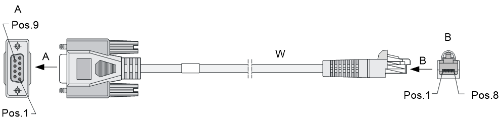
Table7-1 RJ-45 connector pinout
|
RJ-45 |
Signal |
DB-9 |
Signal |
|
1 |
RTS |
8 |
CTS |
|
2 |
DTR |
6 |
DSR |
|
3 |
TXD |
2 |
RXD |
|
4 |
SG |
5 |
SG |
|
5 |
SG |
5 |
SG |
|
6 |
RXD |
3 |
TXD |
|
7 |
DSR |
4 |
DTR |
|
8 |
CTS |
7 |
RTS |
Ethernet twisted pair cable
Introduction
An Ethernet twisted pair cable consists of four pairs of insulated copper wires twisted together. Every wire uses a different color, and has a diameter of about 1 mm (0.04 in). A pair of twisted copper cables can cancel the electromagnetic radiation of each other, and reduce interference of external sources. An Ethernet twisted pair cable typically transmits analog signals and is advantageous in transmitting data over shorter distances. It is the commonly used transmission media of the Ethernet. The maximum transmission distance of the Ethernet twisted pair cable is 100 m (328.08 ft). To extend the transmission distance, you can connect two twisted pair cable segments with a repeater. At most four repeaters can be added, which means five segments can be joined together to provide a transmission distance of 500 m (1640.42 ft).
Ethernet twisted pair cables can be classified into category 3, category 4, category 5, category 5e, category 6, and category 7 cables based on performance. In LANs, category 5, category 5e, and category 6 are commonly used.
Table7-2 Description for commonly used Ethernet twisted pair cables
|
Type |
Description |
|
Category 5 |
Suitable for data transmission at a maximum speed of 100 Mbps |
|
Category 5e |
Suitable for data transmission at a maximum speed of 1000 Mbps |
|
Category 6 |
Suitable for data transmission at a speed higher than 1 Gbps |
Based on whether a metal shielding is used, Ethernet twisted pair cables can be classified into shielded twisted pair (STP) and unshielded twisted pair (UTP). An STP cable provides a metallic braid between the twisted pairs and the outer jacket. This metallic braid helps reduce radiation, prevent information from being listened, and eliminate external electromagnetic interference (EMI) of external sources. STPs have strict application requirements and are expensive although they provide better EMI prevention performance than UTPs. So in most LANs, UTPs are commonly used.
An Ethernet twisted pair cable connects network devices through the RJ-45 connectors at the two ends. Figure7-2 shows the pinouts of an RJ-45 connector.
Figure7-2 RJ-45 connector pinout
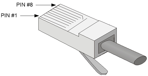
|
|
NOTE: The RJ-45 Ethernet ports on the device use category 5 or above Ethernet twisted pair cables for connection. |
EIA/TIA cabling specifications define two standards, 568A and 568B, for cable pinouts.
· Standard 568A—pin 1: white/green stripe, pin 2: green solid, pin 3: white/orange stripe, pin 4: blue solid, pin 5: white/blue stripe, pin 6: orange solid, pin 7: white/brown stripe, pin 8: brown solid.
· Standard 568B—pin 1: white/orange stripe, pin 2: orange solid, pin 3: white/green stripe, pin 4: blue solid, pin 5: white/blue stripe, pin 6: green solid, pin 7: white/brown stripe, pin 8: brown solid.
Ethernet twisted pair cables can be classified into straight-through and crossover cables based on their pinouts.
· Straight-through—The pinouts at both ends are T568B compliant, as shown in Figure7-3.
· Crossover—The pinouts are T568B compliant at one end and T568A compliant at the other end, as shown in Figure7-4.
Figure7-3 Straight-through cable
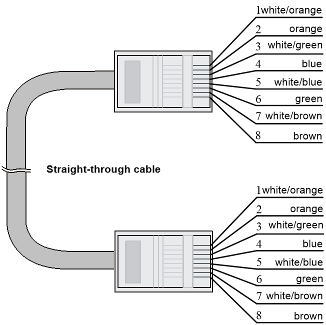

Select an Ethernet twisted pair cable according to the RJ-45 Ethernet port type on your device. An RJ-45 Ethernet port can be MDI or MDIX. Table7-3 and Table7-4 show their pinouts.
Table7-3 RJ-45 MDI port pinouts
|
Pin |
10Base-T/100Base-TX |
1000Base-T |
||
|
Signal |
Function |
Signal |
Function |
|
|
1 |
Tx+ |
Sends data |
BIDA+ |
Bi-directional data cable A+ |
|
2 |
Tx- |
Sends data |
BIDA- |
Bi-directional data cable A- |
|
3 |
Rx+ |
Receives data |
BIDB+ |
Bi-directional data cable B+ |
|
4 |
Reserved |
N/A |
BIDC+ |
Bi-directional data cable C+ |
|
5 |
Reserved |
N/A |
BIDC- |
Bi-directional data cable C- |
|
6 |
Rx- |
Receives data |
BIDB- |
Bi-directional data cable B- |
|
7 |
Reserved |
N/A |
BIDD+ |
Bi-directional data cable D+ |
|
8 |
Reserved |
N/A |
BIDD- |
Bi-directional data cable D- |
Table7-4 RJ-45 MDIX port pinouts
|
Pin |
10Base-T/100Base-TX |
1000Base-T |
||
|
Signal |
Function |
Signal |
Function |
|
|
1 |
Rx+ |
Receives data |
BIDB+ |
Bi-directional data cable B+ |
|
2 |
Rx- |
Receives data |
BIDB- |
Bi-directional data cable B- |
|
3 |
Tx+ |
Sends data |
BIDA+ |
Bi-directional data cable A+ |
|
4 |
Reserved |
N/A |
BIDD+ |
Bi-directional data cable D+ |
|
5 |
Reserved |
N/A |
BIDD- |
Bi-directional data cable D- |
|
6 |
Tx- |
Sends data |
BIDA- |
Bi-directional data cable A- |
|
7 |
Reserved |
N/A |
BIDC+ |
Bi-directional data cable C+ |
|
8 |
Reserved |
N/A |
BIDC- |
Bi-directional data cable C- |
To ensure normal communication, the pins for sending data on one port must correspond to the pins for receiving data on the peer port. When both ports on the two devices are MDI or MDIX, use a crossover Ethernet cable. When one port is MDI and the other is MDIX, use a straight-through Ethernet cable. To summarize, straight-through and crossover cables connect the following devices:
· Straight-through cables connect devices of different types—For example, router to PC and router to switch.
· Crossover cables connect devices of the same type—For example, switch to switch, router to router, and PC to PC.
If an RJ-45 Ethernet port is enabled with MDI/MDIX autosensing, it can automatically negotiate pin roles.
|
|
NOTE: The RJ-45 Ethernet ports on the device support MDI/MDIX autosensing. |
Making an Ethernet twisted pair cable
1. Cut the cable to a required length with the crimping tool.
2. Strip off an appropriate length of the cable sheath. The length is typically that of the RJ-45 connector.
3. Untwist the pairs so that they can lay flat, and arrange the colored wires based on the wiring specifications.
4. Cut the top of the wires even with one another and insert the wires into the RJ-45 connector. Make sure the wires extend to the front of the RJ-45 connector and make good contact with the metal contacts in the RJ-45 connector and in the correct order.
5. Crimp the RJ-45 connector with the crimping tool until you hear a click.
6. Use a cable tester to verify the connectivity of the cable.
Optical fiber
Optical fibers feature low loss and long transmission distance.
Optical fibers can be classified into single-mode fibers and multimode fibers. A single-mode fiber (with yellow jacket) carries only a single ray of light; a multimode fiber (with orange jacket) carries multiple modes of lights.
Table7-5 Characteristics of single-mode and multimode optical fibers
|
Item |
Single-mode fiber |
Multimode fiber |
|
Core |
Small core (10 micrometers or less) |
Larger core than the single-mode fiber (50 micrometers, 62.5 micrometers, or greater) |
|
Dispersion |
Less dispersion |
Allows greater dispersion and therefore, signal loss exists. |
|
Light source and transmission distance |
Uses lasers as the light source often within campus backbones for distance of several thousand meters |
Uses LEDs as the light source often within LANs or distances of a couple hundred meters within a campus network |
Table7-6 Allowed maximum tensile force and crush load
|
Period of force |
Tensile load (N) |
Crush load (N/mm) |
|
Short period |
150 |
500 |
|
Long term |
80 |
100 |
Fiber connectors are indispensable passive components in an optical fiber communication system. They allow the removable connection between optical channels, which makes the optical system debugging and maintenance more convenient. There are multiple types of fiber connectors. Figure7-5 shows an LC connector.
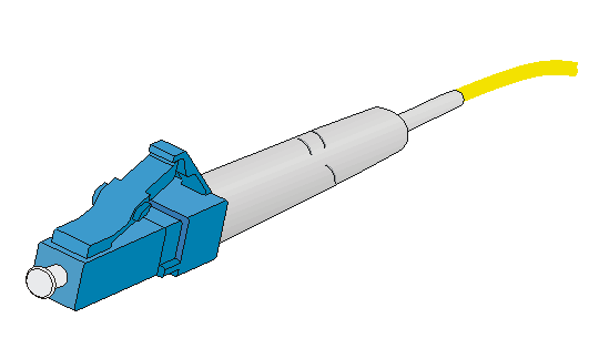
Follow these guidelines when you connect an optical fiber:
· Before connecting an optical fiber, make sure the connector and cable type match the interface module.
· The Ethernet fiber ports on the device support only LC connectors.
· Before connecting an optical fiber, use dust free paper and absolute alcohol to clean the end face of the fiber connector. You can brush the end faces only in one direction.
· Never bend or curve a fiber.
· If the fiber has to pass through a metallic board hole or bend along the acute side of mechanical parts, the fiber must wear jackets or cushions.
