- Table of Contents
- Related Documents
-
| Title | Size | Download |
|---|---|---|
| 01-NAT configuration | 647.92 KB |
Device access with overlapping addresses
Configuring outbound bidirectional NAT for internal-to-external access through domain name
Restrictions and guidelines: NAT configuration
Configuring interface-based NAT
Interface-based NAT tasks at a glance
Restrictions and guidelines for static NAT configuration
Prerequisites for static NAT configuration
Configuring outbound one-to-one static NAT
Configuring outbound net-to-net static NAT
Configuring inbound one-to-one static NAT
Configuring inbound net-to-net static NAT
Restrictions and guidelines for dynamic NAT configuration
Prerequisites for dynamic NAT configuration
Configuring outbound dynamic NAT
Configuring NAT server mappings
Configuring common NAT server mappings
Configuring load sharing NAT server mappings
Configuring PAT for outbound dynamic NAT
Setting the maximum number of attempts for hardware NAT to allocate ports in PAT mode
Setting the maximum number of sessions that can be established per user for hardware NAT
Configuring NAT logging and SNMP notifications
Configuring NAT session logging
Setting the threshold for resource usage in NAT address groups
Configuring the system logs to carry the MAC addresses of online users in a NAT+BRAS scenario
Configuring SNMP notifications for NAT
Display and maintenance commands for interface-based NAT
Interface-based NAT configuration examples
Example: Configuring outbound one-to-one static NAT
Example: Configuring outbound dynamic NAT (non-overlapping addresses)
Example: Configuring NAT Server for external-to-internal access
Example: Configuring NAT Server for external-to-internal access through domain name
Example: Configuring NAT hairpin in C/S mode
Example: Configuring load sharing NAT Server
Example: Configuring NAT DNS mapping
Example: Configuring NAT log export to the information center
Example: Configuring NAT log export to the log server
NAT overview
Network Address Translation (NAT) translates an IP address in the IP packet header to another IP address. Typically, NAT is configured on gateways to enable private hosts to access external networks and external hosts to access private network resources such as a Web server.
Basic NAT concepts
The following describes basic NAT concepts:
· NAT device—A device configured with NAT. Typically, NAT is configured on the edge device that connects the internal and external networks.
· NAT interface—An interface configured with NAT.
· NAT rule—A rule that NAT follows to translate addresses.
· NAT address—A public IP address used for address translation, and this address is reachable from the external network. The NAT address can be manually assigned or dynamically obtained.
· NAT entry—Stores the mapping between a private IP address and a public IP address. For more information, see "NAT entries."
· Easy IP—Uses the IP address of an interface as the NAT address. The IP address of the interface can be manually assigned or be obtained through DHCP or PPPoE.
· Interface-based NAT—Uses NAT rules configured on a per interface basis to translate packets.
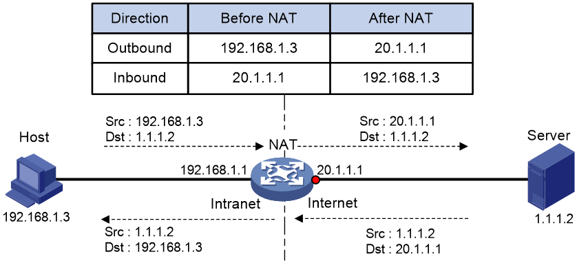
Basic NAT operating mechanism
Figure 1 shows the basic NAT operating mechanism.
2. Upon receiving a response from the server, NAT translates the destination public address to the private address, and forwards the packet to the host.
The NAT operation is transparent to the terminals (the host and the server). NAT hides the private network from the external users and shows that the IP address of the internal host is 20.1.1.1.
NAT control
To control access from internal hosts to external or internal networks for security and management consideration, the NAT device can perform address translation on packets that match specific criteria. This allows for more flexible and practical access control of hosts.
You can use ACLs to implement NAT control. The match criteria in the ACLs include the source IP address, source port number, destination IP address, destination port number, transport layer protocol, user group, and VPN instance. Only packets permitted by an ACL are processed by NAT.
NAT translation methods
Static NAT
Static NAT creates a fixed mapping between a private address and a public address. It supports connections initiated from internal users to external network and from external users to the internal network. Static NAT applies to regular communications.
Dynamic NAT
Dynamic NAT uses an address pool to translate addresses. It applies to the scenario where a large number of internal users access the external network.
NO-PAT
Not Port Address Translation (NO-PAT) translates a private IP address to an IP public address. The public IP address cannot be used by another internal host until it is released.
NO-PAT supports all IP packets.
Port-based PAT
Port Address Translation (PAT) translates multiple private IP addresses to a single public IP address by mapping the private IP address and source port to the public IP address and a unique port. PAT supports TCP and UDP packets, and ICMP request packets.
Figure 2 PAT operation
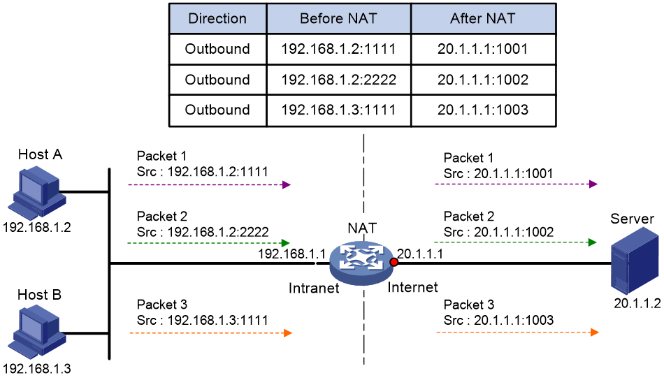
As shown in Figure 2, PAT translates the source IP addresses of the three packets to the same IP public address and translates their port numbers to different port numbers. Upon receiving a response, PAT translates the destination address and port number of the response, and forwards it to the target host.
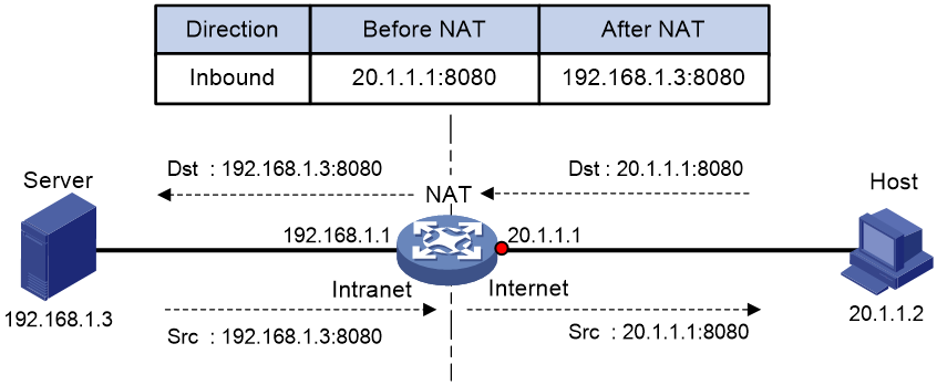
NAT Server
The NAT Server feature maps a public address and port number to the private IP address and port number of an internal server. This feature allows servers in the private network to provide services for external users.
Figure 3 shows how NAT Server works:
1. Upon receiving a request from the host, NAT translates the public destination IP address and port number to the private IP address and port number of the internal server.
2. Upon receiving a response from the server, NAT translates the private source IP address and port number to the public IP address and port number.
PAT
PAT supports the following modes:
· Endpoint-Independent Mapping (EIM).
· Address and Port-Dependent Mapping (APDM).
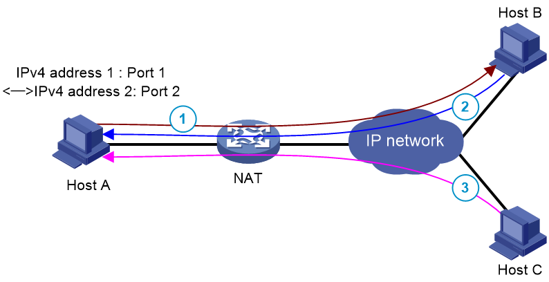
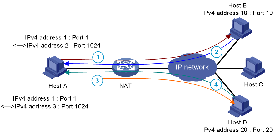
EIM
EIM uses the same IP and port mapping (EIM entry) for packets from the same source IP and port to any destinations. EIM allows external hosts to initiate connections to the translated IP addresses and ports of internal hosts. It allows internal hosts behind different NAT gateways to access each other.
As shown in Figure 4, EIM uses the same IP and port mapping for packets from the same private IPv4 address and port (IPv4 address 1:Port1) to the same public IPv4 address and port (IPv4 2:Port 2).
After an IPv4 private host sends a packet to an IPv4 public host, any IPv4 public host can send packets to the public IPv4 address and port (IPv4 2:Port 2).
Figure 4 PAT operation in EIM mode
APDM
In APDM mode, the translation result depends on the destination IP and port of packets sent from the IPv4 private network to the IPv4 public network. APDM translates the same source IP and port of packets with different destination IP addresses and ports to different public IP addresses and ports or different IP addresses and the same port.
As shown in Figure 5, APDM uses the same IP and port mapping only for packets sourced from the same private IPv4 address and port and destined for the same IPv4 address and port.
An IPv4 public host can actively access an IPv4 private host only after the IPv4 private host has sent a packet to the IPv4 public host.
Figure 5 PAT operation in APDM mode
Port allocation for PAT
An EIM entry is uniquely identified by a three-tuple of source IP address, source port number, and protocol type. A session entry is uniquely identified by a five-tuple of source IP address, source port number, protocol type, destination IP address, and destination port number. Based on the EIM or session entries, you can use the following port allocation methods for PAT:
· Port reuse—Different EIM entries or session entries can use the same port number of a public address as the source port number after address translation.
· Port-by-port—Different EIM entries or session entries must use different port numbers of a public address.
NAT entries
NAT session entry
NAT creates a 5-tuple (source IP address, source port number, protocol type, destination IP address, and destination port number) session entry for a session and creates an address mapping for the first packet in the session.
A NAT session entry contains extended NAT information, such as interface and translation method. Subsequent packets of the session are translated by using this entry.
· If the direction of the subsequent packets is the same as the direction of the first translated packet, NAT performs the source and destination address translation the same as the first packet.
· If the direction of the subsequent packets is opposite to the direction of the first translated packet, NAT perform reverse address translation. For example, if the source address of the first packet is translated, then the destination address of the subsequent packets is translated.
The session management module maintains the updating and aging of NAT session entries. For information about session management, see Security Configuration Guide.
EIM entry
If EIM is configured on the NAT device, the PAT mode will first create a NAT session entry, and then an EIM entry. The EIM entry is a 3-tuple (source IP address, source port number, and protocol type) entry, and it maps a private address/port to a public address/port. The EIM entry ensures:
· Subsequent new connections originating from the same source IP and port uses the same translation as the initial connection.
· Translates the address for new connections initiated from external hosts to the NAT address and port number based on the EIM entry.
An EIM entry ages out after all related NAT session entries age out.
NO-PAT entry
A NO-PAT entry maps a private address to a public address. The same mapping applies to subsequent connections originating from the same source IP.
A NO-PAT entry can also be created during the ALG process for NAT. For information about NAT ALG, see "NAT ALG."
The NO-PAT entry ensures:
· Subsequent new connections originating from the same source IP uses the same translation as the initial connection.
· Translates the address for new connections initiated from hosts that match specific criteria to the NAT address based on the NO-PAT entry.
A NO-PAT entry ages out after all related NAT session entries age out.
Relation entry
NAT ALG translates the IP addresses or port numbers contained in the payload of application-layer packets. On receiving the first packet, the NAT device enabled with ALG creates a relation entry to record the address information carried in the packet. Subsequent packets of the session are translated by using this entry. The address and port information after NAT is used to establish a dynamic channel, and subsequent connections that match the address information will transmit data through the dynamic channel. For more information about relation entries, see session management in Security Configuration Guide.
VRF-aware NAT
VRF-aware NAT allows users from different VRF (VPN instances) to access external networks and to access each other.
1. Upon receiving a request from a user in a VRF to an external network, NAT performs the following tasks:
¡ Translates the private source IP address and port number to a public IP address and port number.
¡ Records the VRF information, such as the VRF name.
2. When a response packet arrives, NAT performs the following tasks:
¡ Translates the destination public IP address and port number to the private IP address and port number.
¡ Forwards the packet to the target VRF.
The NAT Server feature supports VRF-aware NAT for external users to access the servers in a VPN instance. For example, to enable a host at 10.110.1.1 in VPN 1 to provide Web services for Internet users, configure NAT Server to use 202.110.10.20 as the public IP address of the Web server.
NAT hairpin
NAT hairpin allows internal hosts to access each other through NAT. The source and destination IP address of the packets are translated on the interface connected to the internal network.
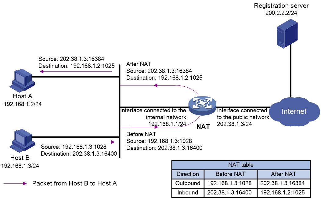
NAT hairpin includes P2P and C/S modes:
· P2P—Allows internal hosts to access each other through NAT. The internal hosts first register their public addresses and ports after NAT to an external server. As shown in Figure 6 and Figure 7, when Host A uses a NAT address to access Host B, Host A first obtains the IP address and port registered by Host B, and then establishes a connection with Host B based on the obtained information.
Figure 6 NAT hairpin in P2P mode (packet from Host A to Host B)
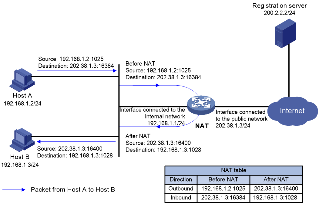
Figure 7 NAT hairpin in P2P mode (packet from Host B to Host A)
· C/S—Allows internal hosts to access internal servers through NAT addresses. As shown in Figure 8 and Figure 9, when the host uses a NAT address to send a packet to the internal FTP server, the NAT device translates both the source and destination IP addresses of the packet. The destination IP address of the packet is translated by matching the NAT Server configuration. The source IP address is translated by matching the outbound dynamic or static NAT entries.
Figure 8 NAT hairpin in C/S mode (packet from the host to the server)
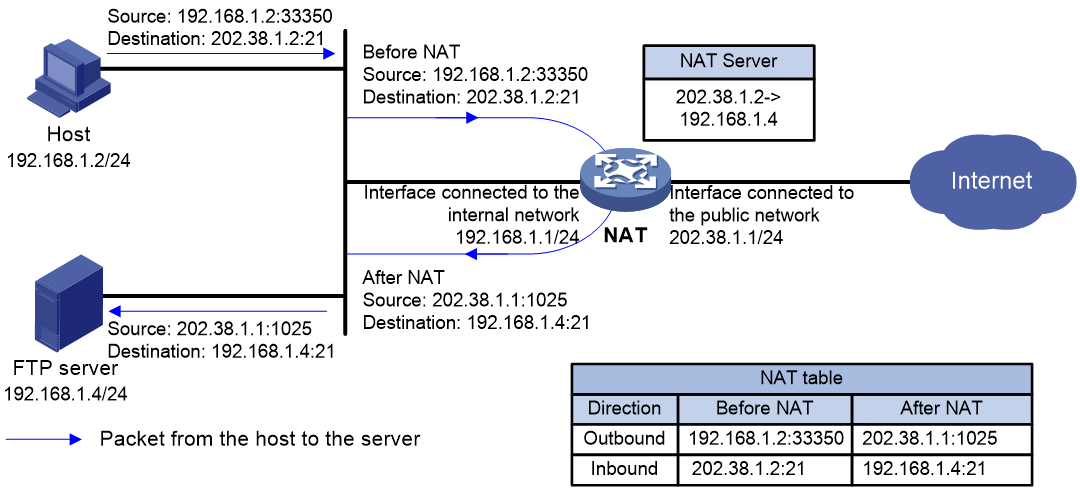
Figure 9 NAT hairpin in C/S mode (packet from the server to the host)

NAT ALG
Typically, NAT only translates IP addresses and port numbers in IP headers. However, packets of some application layer protocols contain IP address or port information in the payload, which also requires translation.
Application Level Gateway (ALG) is used to process packets of application layer protocols. It translates the IP address or port information in the payloads of application layer protocol packets, allowing them to transit.
For example, an FTP application includes a data connection and a control connection. The IP address and port number for the data connection depend on the payload information of the control connection. This requires NAT ALG to translate the address and port information for data connection establishment.
NAT ALG for FTP
In an FTP operation, two TCP connections are established between the client and server, namely, a control connection and a data connection. The control connection transmits control information such as user commands and parameters, including the port information used for initiating the data connection. The data connection forms a data channel between the server and client to transmit files. The need of performing ALG is based on the FTP mode (active or passive) and the locations of the server and client.
Active mode
In FTP active mode, the client issues a PORT command containing the specified port number over the control connection to the server, which then initiates a data connection to the specified port. In this mode, whether to use ALG depends on where the client and the server locate.
· If the client locates on the public network and the server locates on the private network, the client provides a public IP address and port number to the server, which can directly initiate a data connection to the client without ALG.
· If the client locates on the private network and the server locates on the public network, the client provides a private IP address and port number to the server. Then, ALG is used to translate them into a public IP address and port number, which the server uses to initiate a data connection to the client, as shown in Figure 10.
Figure 10 ALG in FTP active mode
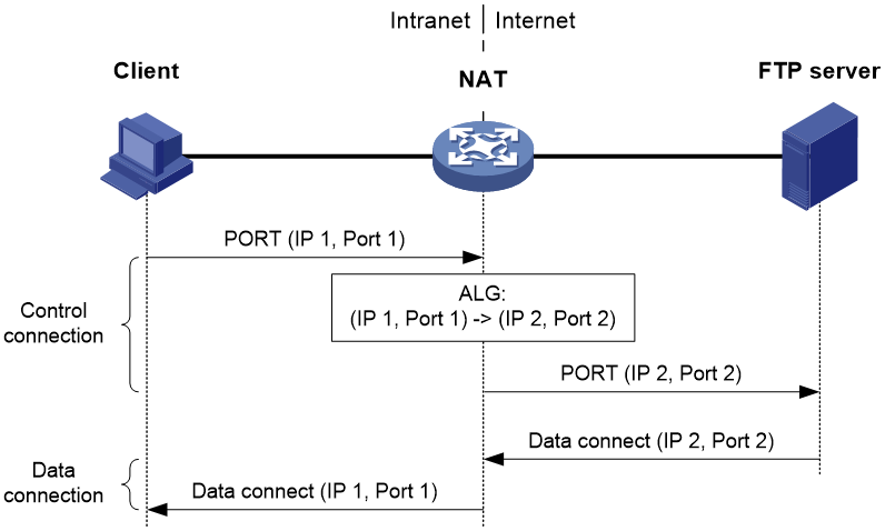
In active mode, FTP ALG works as follows:
1. The client issues a PORT command containing the IP address and port number (IP 1, Port 1) to the server through the NAT device, which is configured with ALG.
2. Upon receiving the command, the NAT device translates the private IP address and port number (IP 1, Port 1) in the payload into a public IP address and port number (IP 2, Port 2), and then creates a PAT entry. This procedure is ALG processing.
3. Upon receiving the command, the server initiates a data connection to the public IP address and port number (IP 2, Port 2) which will be translated into (IP 1, Port 1) by the NAT device.
Passive mode
In FTP passive mode, the client sends a PASV request over the control connection to the server, which then returns a PASV reply containing the specified port to the client. After that, the client initiates a data connection to the specified port of the server. In this mode, whether to use ALG depends on where the client and the server locate.
· If the server locates on the public network and the client locates on the private network, the server provides a public IP address and port number to the client, which can directly initiate a data connection to the server without ALG.
· If the server locates on the private network while the client locates on the public network, the server provides a private IP address and port number to the client. Then, ALG is used to translate them into a public IP address and port number, which the client uses to initiate a data connection to the server, as shown in Figure 11.
Figure 11 ALG in FTP passive mode
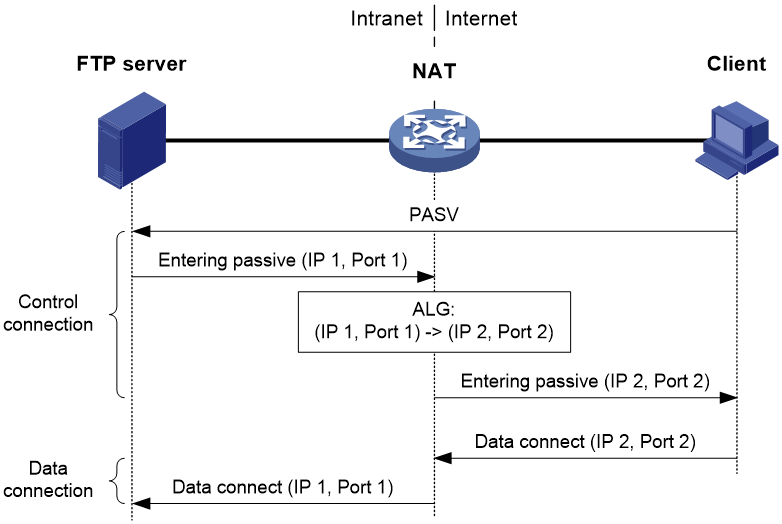
In passive mode, FTP ALG works as follows:
1. The client sends a PASV request to the server.
2. Upon receiving the request, the server chooses an IP address and port number (IP 1, Port 1) for establishing a data channel and sends them in a PASV reply to the client.
3. Upon receiving the reply, the NAT device, which is configured with ALG, translates the private IP address and port number (IP 1, Port 1) in the payload into a public IP address and port number (IP 2, Port 2), creates an PAT entry and sends the reply to the client. This procedure is called ALG processing.
4. Upon receiving the reply, the client initiates a data connection to the public IP address and port number (IP 2, Port 2), which will be translated into (IP 1, Port 1) by the NAT device.
NAT ALG for ICMP
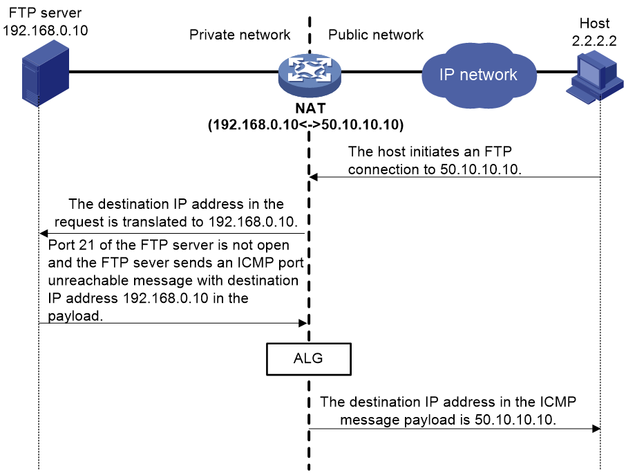
As shown in Figure 12, the public host wants to access the internal FTP server and the public IP address of the FTP server is 50.10.10.10. If port 21 of the FTP server is not open, it sends an ICMP error message to the host upon receiving the request. The IP address in the ICMP error message payload is the private IP address of the FTP server. If the NAT device is not configured with ALG, the host cannot identify the application program of the message and the private IP address of the FTP server is leaked.
To avoid such an issue, configure ALG on the NAT device. ALG translates private IP address 192.168.0.10 in the payload back to public IP address 50.10.10.10 according to the address translation record of the original FTP session. Then, the NAT device sends the ICMP error message to the public network.
Figure 12 ALG processing the ICMP error packet payload
NAT ALG for DNS
As shown in Figure 13, the internal host sends a DNS request for the private IP address of the internal WWW server so that it can access the WWW server by using its domain name. However, the DNS server resides on the public network and it replies with the public IP address of the WWW server. As a result, the internal host cannot access the WWW server. To avoid such an issue, configure ALG on the NAT device so that the public IP address in the DNS response can be translated to the private one.
Figure 13 ALG processing the DNS packet payload
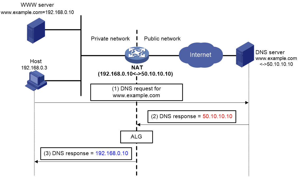
NAT ALG for DNS processes DNS packets as follows:
1. The internal host sends a DNS request to the external DNS server for the IP address of the Web server.
2. Upon receiving the DNS query, the DNS server looks up the local domain name cache for a match. Then, it replies with the corresponding IP address (50.10.10.10).
3. The NAT device configured with ALG translates the public address (50.10.10.10) to the private IP address (192.168.0.10) in the DNS response payload. Then, it sends the DNS response to the internal host.
4. The internal host can access the Web server by using its domain name after receiving the DNS response.
NAT ALG for DNS mapping
DNS mapping resolves the issue that might occur on a specific network configured with traditional NAT ALG. As shown in Figure 14, the DNS server resides on the public network. The NAT device maps multiple private IP addresses to a single public IP address and is configured with NAT ALG. When the internal host accesses the internal Web server by using its domain name, the NAT device translates the public IP address in the DNS response to the private IP address of an internal server. However, the DNS response payload contains only the domain name and the public IP address of the application server and does not contain the transport protocol type and port number. As a result, the NAT device might incorrectly translate the public IP address in the DNS response into the private IP address of the FTP server. Then, the internal host initiates an HTTP connection to the FTP server and fails to access the FTP server.
To resolve such an issue, configure NAT DNS mapping to map the domain name of an internal server to the public IP address, public port number, and protocol type of the internal server. Configure NAT Server to map the public IP and port to the private IP and port of the internal server.
Figure 14 DNS mapping operating mechanism
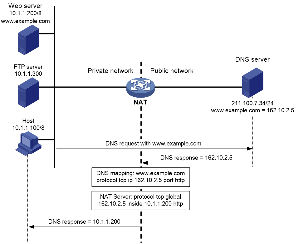
NAT DNS mapping works as follows:
1. The host sends a DNS request containing the domain name of the internal Web server.
2. Upon receiving the DNS response, the NAT device performs a DNS mapping lookup by using the domain name in the response. A NAT DNS mapping maps the domain name to the public IP address, public port number, and the protocol type for the internal server.
3. If a match is found, the NAT device continues to compare the public address, public port number, and the protocol type with the NAT Server configuration. The NAT Server configuration maps the public IP address and port number to the private IP address and port number for the internal server.
4. If a match is found, NAT translates the public IP address in the response into the private IP address of the Web server.
5. The internal host receives the DNS response, and obtains the private IP address of the Web server.
Device access with overlapping addresses
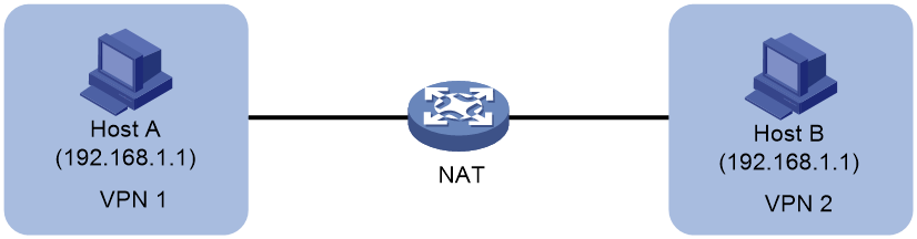
Configuring twice NAT
As shown in Figure 15, two hosts are in different VPN instances with overlapping addresses. For the hosts to access each other, both the source and destination addresses of packets between the two VPNs need to be translated. Configure static NAT on both interfaces connected to the VPNs on the NAT device.
1. Configure a static outbound NAT mapping between 192.168.1.1 in VPN 1 and 172.16.1.1 in VPN 2.
2. Configure a static outbound NAT mapping between 192.168.1.1 in VPN 2 and 172.16.2.1 in VPN 1.
3. When the twice NAT takes effect, the hosts can access each other.
Figure 15 VPN access with overlapping address
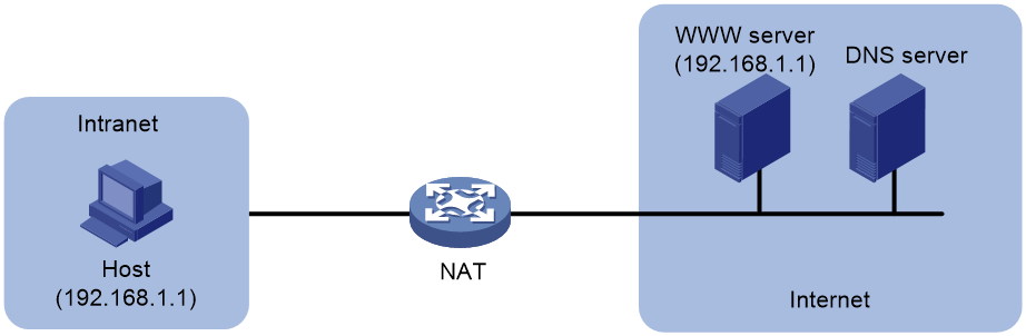
Configuring outbound bidirectional NAT for internal-to-external access through domain name
As shown in Figure 16, the IP address of the Web server overlaps with the private host at 192.168.1.0/24. Configure dynamic NAT ALG and outbound dynamic NAT to allow the internal host to access the external Web server by using the server's domain name.
1. The host sends a DNS request to the DNS server in the external network.
2. After receiving a DNS reply, the NAT device with NAT ALG configured translates the Web server's IP address in the DNS reply payload to a dynamically assigned public address 10.1.1.1.
3. Configure inbound dynamic NAT ALG to make sure the internal host reaches the Web server instead of another internal host. NAT ALG can translate the Web server's IP address in the DNS reply payload to a dynamically assigned public address 10.1.1.1.
4. After receiving the DNS reply from the NAT device, the host sends a packet with the source IP address 192.168.1.1 and destination IP address 10.1.1.1.
5. The NAT device with outbound dynamic NAT configured translates the source IP address of the packet to a dynamically assigned public address 20.1.1.1. NAT ALG translates the destination IP address of the packet to the IP address of the Web server.
Figure 16 Internal-to-external access through domain name
Hardware NAT
For software NAT, the CPU processes NAT services. Software NAT has high requirements for CPU performance.
For hardware NAT, the hardware chip processes NAT services. Hardware NAT transfers the features that consume CPU performance to the hardware chip for processing, so that the CPU can timely process other important tasks. Hardware NAT performance is not limited by the CPU performance.
Hardware NAT is provided by the hardware chip of an interface card, which is applicable to scenarios that have high requirements for NAT processing performance. In the current software version, hardware NAT supports few commands, and only interface-based NAT supports hardware NAT.
Enable hardware NAT on the device in scenarios that meet the following conditions:
· The device is installed with an interface card that supports hardware NAT.
· The commands supported by hardware NAT can meet service requirements.
· The scenarios have high requirements for NAT processing performance.
As a best practice, do not enable hardware NAT in other scenarios.
Restrictions and guidelines: NAT configuration
The general restrictions and guidelines are as follows:
· If you perform all the translation methods, the NAT rules are sorted in the following descending order:
a. NAT Server.
b. Static NAT.
· After NAT is configured, editing the ACL rule in a QoS policy affects only subsequent traffic and does not affect the NATed traffic.
· When you use a QoS policy configured in modular QoS configuration (MQC) approach to redirect traffic to a NAT instance, the device works as follows:
If the QoS policy applied to an interface and the policy-based routing configured on the interface matches the same traffic (for example, they reference the same ACL rule), the policy-based routing configuration takes effect. The device does not match the traffic with the QoS policy.
· After you switch the traffic redirecting action to redirecting traffic to a specified card, or from redirecting to a specified card to another redirecting action, clear the fast forwarding table for the card by using the reset ip fast-forwarding cache slot command.
If all equal-cost output interfaces are configured with interface-based NAT, make sure the NAT configurations on all them are the same. If the NAT configurations are different, NAT uses the NAT configuration on only one interface for address translation, leading to unexpected results and NAT address waste.
Configuring interface-based NAT
About interface-based NAT
Interface-based NAT rules are applied to interfaces. Only traffic on an interface applied with NAT rules is to be matched and address translation will be performed on the traffic that matches a NAT rule. Interface-based NAT is applicable to a network with fixed output interfaces.
Interface-based NAT tasks at a glance
To configure NAT on an interface, perform the following tasks:
¡ Configuring outbound one-to-one static NAT
¡ Configuring outbound net-to-net static NAT
¡ Configuring inbound one-to-one static NAT
¡ Configuring inbound net-to-net static NAT
¡ Configuring outbound dynamic NAT
3. Configuring NAT server mappings
¡ Configuring common NAT server mappings
¡ Configuring load sharing NAT server mappings
4. (Optional.) Configuring PAT for outbound dynamic NAT
5. (Optional.) Configuring NAT hairpin
6. (Optional.) Configuring NAT ALG
7. (Optional.) Configuring hardware NAT features
¡ Setting the maximum number of attempts for hardware NAT to allocate ports in PAT mode
¡ Setting the maximum number of sessions that can be established per user for hardware NAT
8. (Optional.) Configuring NAT logging and SNMP notifications
¡ Configuring NAT session logging
¡ Setting the threshold for resource usage in NAT address groups
¡ Configuring SNMP notifications for NAT
Configuring static NAT
Restrictions and guidelines for static NAT configuration
Typically, configure inbound static NAT with outbound dynamic NAT, NAT Server, or outbound static NAT to implement bidirectional NAT.
Prerequisites for static NAT configuration
Before configuring static NAT, you must perform the following tasks:
· Configure an ACL to identify the IP addresses to be translated. For more information about ACLs, see ACL and QoS Configuration Guide.
· Manually add a route for inbound static NAT. Use local-ip or local-network as the destination address, and use global-ip, an address in global-network, or the next hop directly connected to the output interface as the next hop.
Configuring outbound one-to-one static NAT
About this task
For address translation from a private IP address to a public IP address, configure outbound one-to-one static NAT on the interface connected to the external network.
· When the source IP address of a packet from the private network matches the local-ip, the source IP address is translated into the global-ip.
· When the destination IP address of a packet from the public network matches the global-ip, the destination IP address is translated into the local-ip.
Procedure
1. Enter system view.
system-view
2. Configure a one-to-one mapping for outbound static NAT.
nat static outbound local-ip [ vpn-instance local-vpn-instance-name ] global-ip [ vpn-instance global-vpn-instance-name ] [ acl { ipv4-acl-number | name ipv4-acl-name } [ reversible ] ] [ packet-type-ignore ]
3. Enter interface view.
interface interface-type interface-number
4. Enable static NAT on the interface.
nat static enable
By default, static NAT is disabled.
Configuring outbound net-to-net static NAT
About this task
For address translation from a private network to a public network, configure outbound net-to-net static NAT on the interface connected to the external network.
· When the source IP address of a packet from the private network matches the private address range, the source IP address is translated into a public address in the public address range.
· When the destination IP address of a packet from the public network matches the public address range, the destination IP address is translated into a private address in the private address range.
Procedure
1. Enter system view.
system-view
2. Configure a net-to-net mapping for outbound static NAT.
nat static outbound net-to-net local-start-address local-end-address [ vpn-instance local-vpn-instance-name ] global global-network { mask-length | mask } [ vpn-instance global-vpn-instance-name ] [ acl { ipv4-acl-number | name ipv4-acl-name } [ reversible ] ]
3. Enter interface view.
interface interface-type interface-number
4. Enable static NAT on the interface.
nat static enable
By default, static NAT is disabled.
Configuring inbound one-to-one static NAT
About this task
For address translation from a public IP address to a private IP address, configure inbound one-to-one static NAT.
· When the source IP address of a packet from the public network to the private network matches the global-ip, the source IP address is translated into the local-ip.
· When the destination IP address of a packet from the private network to the public network matches the local-ip, the destination IP address is translated into the global-ip.
Procedure
1. Enter system view.
system-view
2. Configure a one-to-one mapping for inbound static NAT.
nat static inbound global-ip [ vpn-instance global-vpn-instance-name ] local-ip [ vpn-instance local-vpn-instance-name ] [ acl { ipv4-acl-number | name ipv4-acl-name } [ reversible ] ] [ packet-type-ignore ]
3. Enter interface view.
interface interface-type interface-number
4. Enable static NAT on the interface.
nat static enable
By default, static NAT is disabled.
Configuring inbound net-to-net static NAT
About this task
For address translation from a public network to a private network, configure inbound net-to-net static NAT.
· When the source IP address of a packet from the public network matches the public address range, the source IP address is translated into a private address in the private address range.
· When the destination IP address of a packet from the private network matches the private address range, the destination IP address is translated into a public address in the public address range.
Procedure
1. Enter system view.
system-view
2. Configure a net-to-net mapping for inbound static NAT.
nat static inbound net-to-net global-start-address global-end-address [ vpn-instance global-vpn-instance-name ] local local-network { mask-length | mask } [ vpn-instance local-vpn-instance-name ] [ acl { ipv4-acl-number | name ipv4-acl-name } [ reversible ] ]
3. Enter interface view.
interface interface-type interface-number
4. Enable static NAT on the interface.
nat static enable
By default, static NAT is disabled.
Configuring dynamic NAT
Restrictions and guidelines for dynamic NAT configuration
You can configure multiple inbound or outbound dynamic NAT rules.
· A NAT rule with an ACL takes precedence over a rule without any ACL.
· If two ACL-based dynamic NAT rules are configured, the rule with the higher ACL number has higher priority.
· In the NAT and BRAS unification scenario, the device goes through NAT rules on all the interfaces in ascending order of interface index after a user passes authentication. When a packet matches an ACL permit rule on an interface with smaller interface index, the matching process stops. To avoid incorrect traffic matching and translation, configure ACL rules in the NAT rules appropriately.
Prerequisites for dynamic NAT configuration
Before configuring dynamic NAT, you must perform the following tasks:
· Configure an ACL to identify the IP addresses to be translated. For more information about ACLs, see ACL and QoS Configuration Guide.
· Determine whether to enable the Easy IP feature. If you use the IP address of an interface as the NAT address, you are configuring Easy IP.
· Determine a public IP address range for address translation.
· Determine whether to translate port numbers. Use NO-PAT to translate only IP addresses and PAT to translate both IP addresses and port numbers.
Configuring outbound dynamic NAT
About this task
Outbound dynamic NAT translates private IP addresses into public IP addresses.
Restrictions and guidelines
Interface-based outbound dynamic NAT is typically configured on the interface connected to the external network.
Procedure
1. Enter system view.
system-view
2. Create a NAT address group and enter its view.
nat address-group group-id [ vpn-instance vpn-instance-name ]
3. Add an address range to the address group.
address start-address end-address
By default, an address group does not have any address ranges.
You can add multiple address ranges to an address group, but the address ranges must not overlap.
4. Return to system view.
quit
5. Enter interface view.
interface interface-type interface-number
6. Configure outbound dynamic NAT on the interface. Choose the options to configure as needed:
¡ Configure NO-PAT.
nat outbound [ ipv4-acl-number | name ipv4-acl-name ] address-group group-id [ vpn-instance vpn-instance-name ] no-pat [ reversible ]
¡ Configure PAT.
nat outbound [ ipv4-acl-number | name ipv4-acl-name ] [ address-group group-id ] [ vpn-instance vpn-instance-name ] [ port-preserved ]
You can configure multiple outbound dynamic NAT rules on an interface.
|
Parameter |
Description |
|
address-group |
If you do not specify this keyword, the IP address of the interface is used as the NAT address. Easy IP is implemented. |
|
no-pat reversible |
If you specify these keywords, you enable reverse address translation. Reverse address translation uses existing NO-PAT entries to translate the destination address for connections actively initiated from the external network to the internal network. The destination address is translated into the private IP address in the matching NO-PAT entry. |
Configuring NAT server mappings
About NAT server mappings
Typically, the NAT Server feature is configured on the interface connected to the external network to allow servers in the private network or VPN instance to provide services for external users. It maps a public IP address and port number to the private IP address and port number of the internal server.
The NAT Server feature can be implemented by the following methods:
· Common NAT server mappings—Maps the private IP address and the port number of the internal server to a public IP address and a port number. This method allows external hosts to access the internal server by using the specified public IP address.
· Load sharing NAT server mappings—You can add multiple internal servers to an internal server group so that these servers provide the same service for external hosts. The NAT device chooses one internal server based on the weight and number of connections of the servers to respond to a request from an external host to the public address of the internal server group.
· ACL-based NAT server mappings—An extension of common NAT server mapping. A common NAT server mapping maps the private IP address of the internal server to a single public IP address. An ACL-based NAT server mapping the private IP address of the internal server to a set of public IP addresses defined by an ACL. If the destination address of a packet matches a permit rule in the ACL, the destination address is translated into the private IP address of the internal server.
Configuring common NAT server mappings
Restrictions and guidelines
Typically, interface-based NAT server mappings are configured on the interface connected to the external network.
Procedure
1. Enter system view.
system-view
2. Enter interface view.
interface interface-type interface-number
3. Configure common NAT server mappings. Choose the options to configure as needed:
¡ A single public address with a single or no public port:
nat server [ protocol pro-type ] global { global-address | current-interface | interface interface-type interface-number } [ global-port ] [ vpn-instance global-vpn-instance-name ] inside local-address [ local-port ] [ vpn-instance local-vpn-instance-name ] [ acl { ipv4-acl-number | name ipv4-acl-name } ] [ reversible ]
¡ A single public address with consecutive public ports:
nat server protocol pro-type global { global-address | current-interface | interface interface-type interface-number } global-port1 global-port2 [ vpn-instance global-vpn-instance-name ] inside { { local-address | local-address1 local-address2 } local-port | local-address local-port1 local-port2 } [ vpn-instance local-vpn-instance-name ] [ acl { ipv4-acl-number | name ipv4-acl-name } ]
¡ Consecutive public addresses with no public port:
nat server protocol pro-type global global-address1 global-address2 [ vpn-instance global-vpn-instance-name ] inside { local-address | local-address1 local-address2 } [ local-port ] [ vpn-instance local-vpn-instance-name ] [ acl { ipv4-acl-number | name ipv4-acl-name } ]
¡ Consecutive public addresses with a single public port:
nat server protocol pro-type global global-address1 global-address2 global-port [ vpn-instance global-vpn-instance-name ] inside { local-address [ local-port1 local-port2 ] | [ local-address | local-address1 local-address2 ] [ local-port ] } [ vpn-instance local-vpn-instance-name ] [ acl { ipv4-acl-number | name ipv4-acl-name } ]
You can configure multiple NAT server mappings on an interface.
Configuring load sharing NAT server mappings
Restrictions and guidelines
When you configure load shared internal servers, you must make sure a user uses the same public address and public port to access the same service on an internal server. For this purpose, make sure value N in the following mappings is equal to or less than the number of servers in the internal server group:
· One public address and N consecutive public port numbers are mapped to one internal server group.
· N consecutive public addresses and one public port number are mapped to one internal server group.
Procedure
1. Enter system view.
system-view
2. Create a NAT Server group and enter its view.
nat server-group group-id
By default, no NAT Server groups exist.
3. Add an internal server into the group.
inside ip inside-ip port port-number [ weight weight-value ]
You can add multiple internal servers to a group.
4. Return to system view.
quit
5. Enter interface view.
interface interface-type interface-number
6. Configure load sharing NAT server mapping.
nat server protocol pro-type global { { global-address | current-interface | interface interface-type interface-number } { global-port | global-port1 global-port2 } | global-address1 global-address2 global-port } [ vpn-instance global-vpn-instance-name ] inside server-group group-id [ vpn-instance local-vpn-instance-name ] [ acl { ipv4-acl-number | name ipv4-acl-name } ]
You can configure multiple load sharing NAT server mappings on an interface.
Configuring PAT for outbound dynamic NAT
About this task
PAT for outbound dynamic NAT supports the following modes:
· Endpoint-Independent Mapping (EIM)—Uses the same IP and port mapping (EIM entry) for packets from the same source IP and port to any destinations. EIM allows external hosts to initiate connections to the translated IP addresses and ports of internal hosts. It allows internal hosts behind different NAT gateways to access each other.
· Address and Port-Dependent Mapping (APDM)—Uses different IP and port mappings for packets from the same source IP and port to different destination IP addresses and ports. APDM allows an external host to initiate connections to an internal host only under the condition that the internal host has previously accessed the external host. It is secure, but it does not allow internal hosts behind different NAT gateways to access each other.
· Connection-Dependent Mapping (CDM)—Uses the same IP and port mapping for packets of the same connection. Different IP and port mappings are used for different connections although the connections might have the same source IP address and port number. It is secure because it allows an external host to access an internal host only under the condition that the internal host has previously accessed the external host.
Select a mode for outbound dynamic PAT based on service requirements.
Procedure
1. Enter system view.
system-view
2. Specify the Endpoint-Independent Mapping mode for outbound dynamic PAT.
nat mapping-behavior endpoint-independent { tcp [ tcp-5-tuple ] | udp [ udp-5-tuple ] } *
The default mapping mode is Connection-Dependent Mapping.
Configuring NAT hairpin
Restrictions and guidelines
NAT hairpin works in conjunction with NAT Server, outbound dynamic NAT, or outbound static NAT. To provide service correctly, you must configure NAT hairpin on the same interface module as its collaborative NAT feature.
To configure the P2P mode, you must configure outbound PAT on the interface connected to the external network and enable the EIM mapping mode.
Procedure
1. Enter system view.
system-view
2. Enter interface view.
interface interface-type interface-number
3. Enable NAT hairpin.
nat hairpin enable
By default, NAT hairpin is enabled, and cannot be disabled.
Configuring NAT ALG
Configuring NAT ALG
About this task
Typically, NAT only translates IP addresses and port numbers in IP headers. However, packets of some application layer protocols contain IP address or port information in the payload, which also requires translation.
NAT ALG translates address or port information in the application layer payloads to ensure connection establishment.
Procedure
1. Enter system view.
system-view
2. Enable NAT ALG for a protocol or all protocols.
nat alg { all | dns | ftp | h323 | icmp-error | ils | mgcp | nbt | pptp | rsh | rtsp | sccp | sip | sqlnet | tftp | xdmcp }
By default, NAT ALG is disabled for all supported protocols except for FTP, ICMP error packets, and RTSP.
Configuring NAT DNS mapping
Restrictions and guidelines
NAT DNS mapping works in conjunction with NAT Server. NAT DNS mapping maps the domain name of an internal server to the public IP address, public port number, and protocol type of the internal server. NAT Server maps the public IP and port to the private IP and port of the internal server.
Procedure
1. Enter system view.
system-view
2. Configure a NAT DNS mapping.
nat dns-map domain domain-name protocol pro-type { interface interface-type interface-number | ip global-ip } port global-port
You can configure multiple NAT DNS mappings.
Configuring hardware NAT
About this task
Hardware NAT is provided by the hardware chip of an interface card, which is applicable to scenarios that have high requirements for NAT processing performance.
Restrictions and guidelines
In the current software version, hardware NAT supports few commands, and only interface-based NAT supports hardware NAT.
Enable hardware NAT on the device in scenarios that meet the following conditions:
· The device is installed with an interface card that supports hardware NAT.
· The commands supported by hardware NAT can meet service requirements.
· The scenarios have high requirements for NAT processing performance.
As a best practice, do not enable hardware NAT in other scenarios.
Hardware NAT supports the following commands:
· nat address-group
· address
· nat alg
· nat hairpin enable
· nat log enable
· nat log flow-begin
· nat log flow-end
· nat outbound
· nat server
· nat service
· nat static enable
· nat static outbound
· nat static outbound net-to-net
For information about support for the parameters in a command, see the command reference.
Prerequisites
When you use the hardware chip of an interface card for processing NAT services, redirect traffic to the interface card as follows:
· To redirect traffic from the public network to the private network, use the nat service command and specify the interface card.
· To redirect traffic from the private network to the public network, configure a QoS policy to redirect traffic to the interface card specified in the nat service command.
Procedure
1. Enter system view.
system-view
2. Enable hardware NAT.
nat hardware-mode enable
By default, hardware NAT is disabled.
Setting the maximum number of attempts for hardware NAT to allocate ports in PAT mode
About this task
When the device enabled with hardware NAT allocates ports, a conflict in five-tuple after NAT or a port collision causes port allocation failure. In this case, the NAT device automatically attempts to allocate another available port to the private user. Configure this feature to set the maximum number of attempts for hardware NAT to allocate ports.
Restrictions and guidelines
More port collisions indicate greater network delay and processing workload, affecting network performance. As a best practice, use the default setting. To change the maximum number of attempts for hardware NAT to allocate ports, contact H3C Support to make sure the specified maximum number can meet service expectations.
This feature takes effect only after you enable hardware NAT by using the nat hardware-mode enable command.
Procedure
1. Enter system view.
system-view
2. Enable hardware NAT.
nat hardware-mode enable
By default, hardware NAT is disabled.
3. Set the maximum number of attempts for hardware NAT to allocate ports in PAT mode.
nat hardware-mode port-alloc number
By default, hardware NAT attempts to allocate ports in PAT mode up to three times.
Setting the maximum number of sessions that can be established per user for hardware NAT
About this task
Too many sessions established by a single user consume a large number of device port resources and session resources. As a result, other users cannot establish new connections to access the external network. Configure this feature to set the maximum number of sessions that can be established per user.
Restrictions and guidelines
As a best practice, use the default setting. To change the maximum number of sessions that can be established per user for hardware NAT, contact H3C Support to make sure the specified maximum number can meet service expectations.
This feature takes effect only after you enable hardware NAT by using the nat hardware-mode enable command.
Procedure
1. Enter system view.
system-view
2. Enable hardware NAT.
nat hardware-mode enable
By default, hardware NAT is disabled.
3. Set the maximum number of sessions that can be established per user for hardware NAT.
nat hardware-mode user-limit number
By default, a user can establish up to 1024 sessions for hardware NAT.
Setting the maximum number of sessions that all public users can establish to access internal servers for hardware NAT
About this task
Too many sessions established by public users to access internal servers consume a large number of device session resources. As a result, other users cannot establish new sessions. Configure this feature to set the maximum number of sessions that all public users can establish to access internal servers.
Restrictions and guidelines
As a best practice, use the default setting. To change the maximum number of sessions that all public users can establish to access internal servers for hardware NAT, contact H3C Support to make sure the specified maximum number can meet service expectations.
This feature takes effect only after you enable hardware NAT by using the nat hardware-mode enable command.
Procedure
1. Enter system view.
system-view
2. Enable hardware NAT.
nat hardware-mode enable
By default, hardware NAT is disabled.
3. Set the maximum number of sessions that all public users can establish to access internal servers for hardware NAT.
nat hardware-mode server-limit number
By default, all public users can establish up to 262144 sessions to access internal servers for hardware NAT.
Configuring NAT logging and SNMP notifications
Configuring NAT session logging
About this task
NAT session logging records NAT session information, including translation information and access information.
A NAT device generates NAT session logs for the following events:
· NAT flow (NAT session or EIM entry) establishment.
· NAT flow (NAT session or EIM entry) removal. This event occurs when you add a configuration with a higher priority, remove a configuration, change ACLs, when a NAT session ages out, or when you manually delete a NAT session.
· Active NAT flow logging. Active NAT flows refer to NAT sessions that exist within a period of time and undeleted EIM entries. When the specified interval for logging active NAT flows expires, the device records the existing NAT session information or EIM entries and generates a log.
Procedure
1. Enter system view.
system-view
2. Enable NAT logging.
nat log enable [ acl { ipv4-acl-number | name ipv4-acl-name } ]
By default, NAT logging is disabled.
3. Enable NAT session logging.
¡ For NAT flow establishment events:
nat log flow-begin
¡ For NAT flow removal events:
nat log flow-end
¡ For active NAT flows:
nat log flow-active time-value
By default, NAT session logging is disabled.
Setting the threshold for resource usage in NAT address groups
About this task
The device generates a log in the following scenarios:
· The device reports a threshold violation event when the resource usage in a NAT address group reaches or exceeds the threshold.
· The device reports a threshold recovery event when the resource usage in a NAT address group drops below 87.5% of the threshold from a threshold crossing value.
Procedure
1. Enter system view.
system-view
2. Enable NAT logging.
nat log enable [ acl { ipv4-acl-number | name ipv4-acl-name } ]
By default, NAT logging is disabled.
3. Enable logging for resource usage in NAT address groups.
nat address-group-usage enable
By default, logging for resource usage in NAT address groups is enabled.
4. (Optional.) Set the threshold for resource usage in NAT address groups.
nat address-group-usage threshold threshold-value
By default, the threshold for resource usage in NAT address groups is 90%.
Configuring the system logs to carry the MAC addresses of online users in a NAT+BRAS scenario
About this task
After you configure this command, the system logs controlled by the following commands will carry the MAC addresses of online users in a NAT+BRAS scenario:
· nat log port-block port-usage threshold
· nat log port-alloc-fail
Procedure
1. Enter system view.
system-view
2. Configure the system logs to carry the MAC addresses of online users in a NAT+BRAS scenario
nat log format user-mac
By default, the system logs do not carry the MAC addresses of online users in a NAT+BRAS scenario.
Configuring SNMP notifications for NAT
About this task
The device generates an SNMP notification in the following scenarios:
If SNMP notifications are enabled for the address group resource usage:
· The device reports a threshold violation event when the address group resource usage reaches or exceeds the threshold.
· The device reports a threshold recovery event when the address group resource usage drops below 87.5% of the threshold from a threshold crossing value.
To set the threshold for address group resource usage, execute the nat address-group-usage threshold command.
For the notifications to be sent correctly, you must also configure SNMP on the device. For more information about SNMP configuration, see Network Management and Monitoring Configuration Guide.
Procedure
1. Enter system view.
system-view
2. Enable SNMP notifications for NAT.
snmp-agent trap enable nat [ address-group-usage ]
By default, SNMP notifications are enabled for NAT.
Display and maintenance commands for interface-based NAT
Execute display commands in any view and reset commands in user view.
|
Task |
Command |
|
Display all NAT configuration information. |
display nat all |
|
Display NAT address group information. |
display nat address-group [ group-id ] [ resource-usage [ verbose ] ] |
|
Display NAT DNS mapping configuration. |
display nat dns-map |
|
Display information about NAT EIM entries. |
In standalone mode: display nat eim [ slot slot-number ] [ protocol { icmp | tcp | udp } ] [ local-ip { b4 ipv6-address | local-ip } ] [ local-port local-port ] [ global-ip global-ip ] [ global-port global-port ] [ local-vpn local-vpn-instance-name ] In IRF mode: display nat eim [ chassis chassis-number slot slot-number ] [ protocol { icmp | tcp | udp } ] [ local-ip { b4 ipv6-address | local-ip } ] [ local-port local-port ] [ global-ip global-ip ] [ global-port global-port ] [ local-vpn local-vpn-instance-name ] |
|
Display NAT EIM entry statistics. |
In standalone mode: display nat eim statistics [ slot slot-number ] In IRF mode: display nat eim statistics [ chassis chassis-number slot slot-number ] |
|
Display NAT logging configuration. |
display nat log |
|
Display information about NAT NO-PAT entries. |
In standalone mode: display nat no-pat [ slot slot-number ] In IRF mode: display nat no-pat [ chassis chassis-number slot slot-number ] |
|
Display outbound dynamic NAT configuration. |
display nat outbound |
|
Display NAT server mappings. |
display nat server |
|
Display internal server group configuration. |
display nat server-group [ group-id ] |
|
Display NAT sessions. |
In standalone mode: display nat session [ { source-ip source-ip | destination-ip destination-ip } * [ vpn-instance vpn -instance-name ] ] [ protocol { dccp | icmp | raw-ip | sctp | tcp | udp | udp-lite } ] [ slot slot-number ] [ brief | verbose ] In IRF mode: display nat session [ { source-ip source-ip | destination-ip destination-ip } * [ vpn-instance vpn -instance-name ] ] [ protocol { dccp | icmp | raw-ip | sctp | tcp | udp | udp-lite } ] [ chassis chassis-number slot slot-number ] [ brief | verbose ] |
|
Display static NAT mappings. |
display nat static |
|
Display NAT statistics. |
In standalone mode: display nat statistics [ summary ] [ slot slot-number ] In IRF mode: display nat statistics [ summary ] [ chassis chassis-number slot slot-number ] |
|
Delete NAT EIM entries. |
In standalone mode: reset nat eim [ protocol { icmp | tcp | udp } ] [ local-ip { b4 ipv6-address | local-ip } ] [ local-port local-port ] [ global-ip global-ip ] [ global-port global-port ] [ local-vpn local-vpn-instance-name ] [ slot slot-number ] In IRF mode: reset nat eim [ protocol { icmp | tcp | udp } ] [ local-ip { b4 ipv6-address | local-ip } ] [ local-port local-port ] [ global-ip global-ip ] [ global-port global-port ] [ local-vpn local-vpn-instance-name ] [ chassis chassis-number slot slot-number ] |
|
Clear NAT sessions. |
In standalone mode: reset nat session [ protocol { tcp | udp } ] [ slot slot-number ] In IRF mode: reset nat session [ protocol { tcp | udp } ] [ chassis chassis-number slot slot-number ] |
Interface-based NAT configuration examples
Example: Configuring outbound one-to-one static NAT
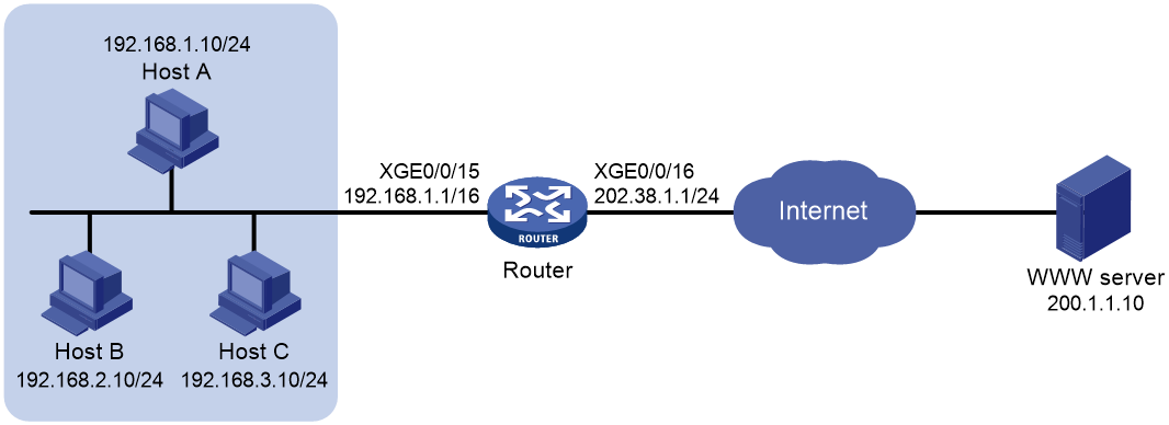
Network configuration
Configure static NAT to allow the host at 10.110.10.8/24 to access the Internet.

Procedure
# Specify IP addresses for the interfaces on the router. (Details not shown.)
# Configure ACL 2001 to identify packets from subnet 10.110.10.0/24.
<Router> system-view
[Router] acl basic 2001
[Router-acl-ipv4-basic-2001] rule permit source 10.110.10.0 0.0.0.255
[Router-acl-ipv4-basic-2001] quit
# Configure a QoS policy to redirect packets matching ACL 2001 to the local card.
[Router] traffic classifier 1
[Router-classifier-1] if-match acl 2001
[Router-classifier-1] quit
[Router] traffic behavior 1
[Router-behavior-1] redirect local
[Router-behavior-1] quit
[Router] qos policy 1
[Router-qospolicy-1] classifier 1 behavior 1
[Router-qospolicy-1] quit
[Router] interface ten-gigabitethernet 0/0/15
[Router-Ten-GigabitEthernet0/0/15] qos apply policy 1 inbound
[Router-Ten-GigabitEthernet0/0/15] quit
# Configure a one-to-one static NAT mapping between the private address 10.110.10.8 and the public address 202.38.1.100.
[Router] nat static outbound 10.110.10.8 202.38.1.100
# Enable static NAT on Ten-GigabitEthernet 0/0/16.
[Router] interface ten-gigabitethernet 0/0/16
[Router-Ten-GigabitEthernet0/0/16] nat static enable
[Router-Ten-GigabitEthernet0/0/16] quit
Verifying the configuration
# Verify that the host at 10.110.10.8/24 can access the server on the Internet. (Details not shown.)
# Display static NAT configuration.
[Router] display nat static
Static NAT mappings:
Totally 1 outbound static NAT mappings.
IP-to-IP:
Local IP : 10.110.10.8
Global IP : 202.38.1.100
Config status: Active
Interfaces enabled with static NAT:
Totally 1 interfaces enabled with static NAT.
Interface: Ten-GigabitEthernet0/0/16
Config status: Active
# Display NAT session information.
[Router] display nat session verbose
Initiator:
Source IP/port: 10.110.10.8/42496
Destination IP/port: 200.1.1.10/2048
DS-Lite tunnel peer: -
VPN instance/VLAN ID/VLL ID: -/-/-
Protocol: ICMP(1)
Inbound interface: Ten-GigabitEthernet0/0/15
Responder:
Source IP/port: 200.1.1.10/42496
Destination IP/port: 202.38.1.100/0
DS-Lite tunnel peer: -
VPN instance/VLAN ID/VLL ID: -/-/-
Protocol: ICMP(1)
Inbound interface: Ten-GigabitEthernet0/0/16
State: ICMP_REPLY
Application: INVALID
Role: -
Failover group ID: -
Start time: 2012-08-16 09:30:49 TTL: 27s
Initiator->Responder: 5 packets 420 bytes
Responder->Initiator: 5 packets 420 bytes
Total sessions found: 1
Example: Configuring outbound dynamic NAT (non-overlapping addresses)
Network configuration
As shown in Figure 18, a company has a private address 192.168.0.0/16 and two public IP addresses 202.38.1.2 and 202.38.1.3. Configure outbound dynamic NAT to allow only internal users on subnet 192.168.1.0/24 to access the Internet.
Procedure
# Specify IP addresses for the interfaces on the router. (Details not shown.)
# Configure ACL 2001 to identify packets from subnet 192.168.1.0/24. In this example, the packets redirected to the service card that provides NAT services require address translation. As a result, the ACL rule defined in ACL 2001 is the same as that defined in ACL 2000. You can define different ACL rules as required.
<Router> system-view
[Router] acl basic 2001
[Router-acl-ipv4-basic-2001] rule permit source 192.168.1.0 0.0.0.255
[Router-acl-ipv4-basic-2001] quit
# Configure a QoS policy to redirect packets matching ACL 2001 to the local card.
[Router] traffic classifier 1
[Router-classifier-1] if-match acl 2001
[Router-classifier-1] quit
[Router] traffic behavior 1
[Router-behavior-1] redirect local
[Router-behavior-1] quit
[Router] qos policy 1
[Router-qospolicy-1] classifier 1 behavior 1
[Router-qospolicy-1] quit
[Router] interface ten-gigabitethernet 0/0/15
[Router-Ten-GigabitEthernet0/0/15] qos apply policy 1 inbound
[Router-Ten-GigabitEthernet0/0/15] quit
# Configure address group 0, and add an address range from 202.38.1.2 to 202.38.1.3 to the group.
[Router] nat address-group 0
[Router-address-group-0] address 202.38.1.2 202.38.1.3
[Router-address-group-0] quit
# Configure ACL 2000 to identify packets from subnet 192.168.1.0/24.
[Router] acl basic 2000
[Router-acl-ipv4-basic-2000] rule permit source 192.168.1.0 0.0.0.255
[Router-acl-ipv4-basic-2000] quit
# Enable outbound dynamic PAT on Ten-GigabitEthernet 0/0/16. The source IP addresses of the packets permitted by the ACL rule is translated into the addresses in address group 0.
[Router] interface ten-gigabitethernet 0/0/16
[Router-Ten-GigabitEthernet0/0/16] nat outbound 2000 address-group 0
[Router-Ten-GigabitEthernet0/0/16] quit
Verifying the configuration
# Verify that Host A can access the WWW server, while Host B cannot. (Details not shown.)
# Display all NAT configuration and statistics.
[Router] display nat all
NAT hardware mode : Disabled
NAT address group information:
Totally 1 NAT address groups.
Address group name/ID: 0/0
Address information:
Start address End address
202.38.1.2 202.38.1.3
NAT outbound information:
Totally 1 NAT outbound rules.
Interface: Ten-GigabitEthernet0/0/16
ACL: 2000 Address group: 0 Port-preserved: N
NO-PAT: N Reversible: N
Config status: Active
NAT logging:
Log enable : Disabled
Log format user-mac : Disabled
Flow-begin : Disabled
Flow-end : Disabled
Flow-active : Disabled
Port-block-assign : Disabled
Port-block-withdraw : Disabled
Port-alloc-fail : Disabled
Port-block-alloc-fail : Disabled
Port-usage : Disabled
Port-block-usage : Enabled(Threshold: 90%)
Address-group-usage : Enabled(Threshold: 90%)
Bandwidth-usage : Enabled(Threshold: 90%)
NAT mapping behavior:
Mapping mode : Connection-Dependent
ACL : ---
Config status: Active
NAT ALG:
DNS : Disabled
FTP : Enabled
H323 : Disabled
ICMP-ERROR : Enabled
ILS : Disabled
MGCP : Disabled
NBT : Disabled
PPTP : Disabled
RTSP : Enabled
RSH : Disabled
SCCP : Disabled
SIP : Disabled
SQLNET : Disabled
TFTP : Disabled
XDMCP : Disabled
NAT Agency ALG:
FTP : Enabled
ICMP-ERROR : Enabled
SIP : Disabled
NAT extended port block report to RADIUS: Disabled
NAT abnormal-cu-connection auto-renew-lease: Disabled
NAT hardware ignore-flowredirect-method : Disabled
# Display NAT session information generated when Host A accesses the WWW server.
[Router] display nat session verbose
Initiator:
Source IP/port: 192.168.1.10/52992
Destination IP/port: 200.1.1.10/2048
DS-Lite tunnel peer: -
VPN instance/VLAN ID/VLL ID: -/-/-
Protocol: ICMP(1)
Inbound interface: Ten-GigabitEthernet0/0/15
Responder:
Source IP/port: 200.1.1.10/4
Destination IP/port: 202.38.1.3/0
DS-Lite tunnel peer: -
VPN instance/VLAN ID/VLL ID: -/-/-
Protocol: ICMP(1)
Inbound interface: Ten-GigabitEthernet0/0/16
State: ICMP_REPLY
Application: INVALID
Role: -
Failover group ID: -
Start time: 2012-08-15 14:53:29 TTL: 12s
Initiator->Responder: 1 packets 84 bytes
Responder->Initiator: 1 packets 84 bytes
Example: Configuring NAT Server for external-to-internal access
Network configuration
As shown in Figure 19, two Web servers, one FTP server and one SMTP server are in the internal network to provide services for external users. The internal network address is 10.110.0.0/16. The company has three public IP addresses from 202.38.1.1/24 to 202.38.1.3/24.
Configure the NAT Server feature to allow the external user to use public address 202.38.1.1/24 to access the internal servers.

Procedure
# Specify IP addresses for the interfaces on the router. (Details not shown.)
# Configure ACL 2001 to identify packets from subnet 10.110.10.0/24.
<Router> system-view
[Router] acl basic 2001
[Router-acl-ipv4-basic-2001] rule permit source 10.110.10.0 0.0.0.255
[Router-acl-ipv4-basic-2001] quit
# Configure a QoS policy to redirect packets matching ACL 2001 to the local card.
[Router] traffic classifier 1
[Router-classifier-1] if-match acl 2001
[Router-classifier-1] quit
[Router] traffic behavior 1
[Router-behavior-1] redirect local
[Router-behavior-1] quit
[Router] qos policy 1
[Router-qospolicy-1] classifier 1 behavior 1
[Router-qospolicy-1] quit
[Router] interface ten-gigabitethernet 0/0/15
[Router-Ten-GigabitEthernet0/0/15] qos apply policy 1 inbound
[Router-Ten-GigabitEthernet0/0/15] quit
# Enter interface view of Ten-GigabitEthernet 0/0/16.
[Router] interface ten-gigabitethernet 0/0/16
# Configure a NAT server mapping to allow external users to access the FTP server by using the address 202.38.1.1 and port 21.
[Router-Ten-GigabitEthernet0/0/16] nat server protocol tcp global 202.38.1.1 21 inside 10.110.10.3 ftp
# Configure a NAT server mapping to allow external users to access the Web server 1 by using the address 202.38.1.1 and port 80.
[Router-Ten-GigabitEthernet0/0/16] nat server protocol tcp global 202.38.1.1 80 inside 10.110.10.1 http
# Configure a NAT server mapping to allow external users to access the Web server 2 by using the address 202.38.1.1 and port 8080.
[Router-Ten-GigabitEthernet0/0/16] nat server protocol tcp global 202.38.1.1 8080 inside 10.110.10.2 http
# Configure a NAT server mapping to allow external users to access the SMTP server by using the address 202.38.1.1 and port number defined by SMTP.
[Router-Ten-GigabitEthernet0/0/16] nat server protocol tcp global 202.38.1.1 smtp inside 10.110.10.4 smtp
[Router-Ten-GigabitEthernet0/0/16] quit
Verifying the configuration
# Verify that the host on the external network can access the internal servers by using the public addresses. (Details not shown.)
# Display all NAT configuration and statistics.
[Router] display nat all
NAT hardware mode : Disabled
NAT internal server information:
Totally 4 internal servers.
Interface: Ten-GigabitEthernet0/0/16
Protocol: 6(TCP)
Global IP/port: 202.38.1.1/21
Local IP/port : 10.110.10.3/21
Config status : Active
Interface: Ten-GigabitEthernet0/0/16
Protocol: 6(TCP)
Global IP/port: 202.38.1.1/25
Local IP/port : 10.110.10.4/25
Config status : Active
Interface: Ten-GigabitEthernet0/0/16
Protocol: 6(TCP)
Global IP/port: 202.38.1.1/80
Local IP/port : 10.110.10.1/80
Config status : Active
Interface: Ten-GigabitEthernet0/0/16
Protocol: 6(TCP)
Global IP/port: 202.38.1.1/8080
Local IP/port : 10.110.10.2/80
Config status : Active
NAT logging:
Log enable : Disabled
Log format user-mac : Disabled
Flow-begin : Disabled
Flow-end : Disabled
Flow-active : Disabled
Port-block-assign : Disabled
Port-block-withdraw : Disabled
Port-alloc-fail : Disabled
Port-block-alloc-fail : Disabled
Port-usage : Disabled
Port-block-usage : Enabled(Threshold: 90%)
Address-group-usage : Enabled(Threshold: 90%)
Bandwidth-usage : Enabled(Threshold: 90%)
NAT mapping behavior:
Mapping mode : Connection-Dependent
ACL : ---
Config status: Active
NAT ALG:
DNS : Disabled
FTP : Enabled
H323 : Disabled
ICMP-ERROR : Enabled
ILS : Disabled
MGCP : Disabled
NBT : Disabled
PPTP : Disabled
RTSP : Enabled
RSH : Disabled
SCCP : Disabled
SIP : Disabled
SQLNET : Disabled
TFTP : Disabled
XDMCP : Disabled
NAT Agency ALG:
FTP : Enabled
ICMP-ERROR : Enabled
SIP : Disabled
NAT extended port block report to RADIUS: Disabled
NAT abnormal-cu-connection auto-renew-lease: Disabled
NAT hardware ignore-flowredirect-method : Disabled
# Display NAT session information generated when Host accesses the FTP server.
[Router] display nat session verbose
Initiator:
Source IP/port: 200.1.1.10/1694
Destination IP/port: 202.38.1.1/21
DS-Lite tunnel peer: -
VPN instance/VLAN ID/VLL ID: -/-/-
Protocol: TCP(6)
Inbound interface: Ten-GigabitEthernet0/0/16
Responder:
Source IP/port: 10.110.10.3/21
Destination IP/port: 200.1.1.10/1694
DS-Lite tunnel peer: -
VPN instance/VLAN ID/VLL ID: -/-/-
Protocol: TCP(6)
Inbound interface: Ten-GigabitEthernet0/0/15
State: TCP_ESTABLISHED
Application: FTP
Role: -
Failover group ID: -
Start time: 2012-08-15 14:53:29 TTL: 3597s
Initiator->Responder: 7 packets 308 bytes
Responder->Initiator: 5 packets 312 bytes
Total sessions found: 1
Example: Configuring NAT Server for external-to-internal access through domain name
Network configuration
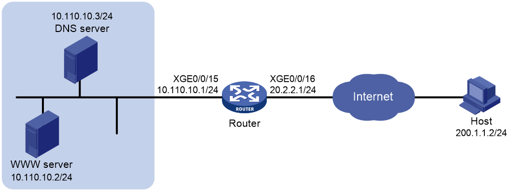
As shown in Figure 20, Web server at 10.110.10.2/24 in the internal network provides services for external users. A DNS server at 10.110.10.3/24 is used to resolve the domain name of the Web server. The company has two public IP addresses: 202.38.1.2 and 202.38.1.3.
Configure NAT Server to allow external users to access the internal Web server by using the domain name.
Analysis
To meet the network configuration requirements, you must perform the following tasks:
· Configure NAT Server to map the private IP address and port of the DNS server to a public address and port. NAT Server allows the external host to access the internal DNS server for domain name resolution.
· Enable ALG for DNS and configure outbound dynamic NAT to translate the private IP address of the Web server in the payload of the DNS response packet into a public IP address.
Procedure
# Specify IP addresses for the interfaces on the router. (Details not shown.)
# Configure ACL 2001 to identify packets from subnet 10.110.10.0/24.
<Router> system-view
[Router] acl basic 2001
[Router-acl-ipv4-basic-2001] rule permit source 10.110.10.0 0.0.0.255
[Router-acl-ipv4-basic-2001] quit
# Configure a QoS policy to redirect packets matching ACL 2001 to the local card.
[Router] traffic classifier 1
[Router-classifier-1] if-match acl 2001
[Router-classifier-1] quit
[Router] traffic behavior 1
[Router-behavior-1] redirect local
[Router-behavior-1] quit
[Router] qos policy 1
[Router-qospolicy-1] classifier 1 behavior 1
[Router-qospolicy-1] quit
[Router] interface ten-gigabitethernet 0/0/15
[Router-Ten-GigabitEthernet0/0/15] qos apply policy 1 inbound
[Router-Ten-GigabitEthernet0/0/15] quit
# Enable NAT ALG for DNS.
[Router] nat alg dns
# Configure ACL 2000 to identify packets from 10.110.10.2.
[Router] acl basic 2000
[Router-acl-ipv4-basic-2000] rule permit source 10.110.10.2 0
[Router-acl-ipv4-basic-2000] quit
# Create address group 1.
[Router] nat address-group 1
# Add address 202.38.1.3 to the group.
[Router-address-group-1] address 202.38.1.3 202.38.1.3
[Router-address-group-1] quit
# Configure NAT Server on Ten-GigabitEthernet 0/0/16 to map the address 202.38.1.1 to 10.110.10.3. External users can access the internal DNS server.
[Router] interface ten-gigabitethernet 0/0/16
[Router-Ten-GigabitEthernet0/0/16] nat server protocol udp global 202.38.1.2 inside 10.110.10.3 dns
# Enable outbound NO-PAT on Ten-GigabitEthernet 0/0/16. Use the address in address group 1 to translate the private address in DNS response payload, and allow reversible NAT.
[Router-Ten-GigabitEthernet0/0/16] nat outbound 2000 address-group 1 no-pat reversible
[Router-Ten-GigabitEthernet0/0/16] quit
Verifying the configuration
# Verify that the host on the external network can access the internal Web server by using the server's domain name. (Details not shown.)
# Display all NAT configuration and statistics.
[Router] display nat all
NAT hardware mode : Disabled
NAT address group information:
Totally 1 NAT address groups.
Address group name/ID: 1/1
Address information:
Start address End address
202.38.1.3 202.38.1.3
NAT outbound information:
Totally 1 NAT outbound rules.
Interface: Ten-GigabitEthernet0/0/16
ACL: 2000 Address group: 1 Port-preserved: N
NO-PAT: Y Reversible: Y
Config status: Active
NAT internal server information:
Totally 1 internal servers.
Interface: Ten-GigabitEthernet0/0/16
Protocol: 17(UDP)
Global IP/port: 202.38.1.2/53
Local IP/port : 10.110.10.3/53
Config status : Active
NAT logging:
Log enable : Disabled
Log format user-mac : Disabled
Flow-begin : Disabled
Flow-end : Disabled
Flow-active : Disabled
Port-block-assign : Disabled
Port-block-withdraw : Disabled
Port-alloc-fail : Disabled
Port-block-alloc-fail : Disabled
Port-usage : Disabled
Port-block-usage : Enabled(Threshold: 90%)
Address-group-usage : Enabled(Threshold: 90%)
Bandwidth-usage : Enabled(Threshold: 90%)
NAT mapping behavior:
Mapping mode : Connection-Dependent
ACL : ---
Config status: Active
NAT ALG:
DNS : Enabled
FTP : Enabled
H323 : Disabled
ICMP-ERROR : Enabled
ILS : Disabled
MGCP : Disabled
NBT : Disabled
PPTP : Disabled
RTSP : Enabled
RSH : Disabled
SCCP : Disabled
SIP : Disabled
SQLNET : Disabled
TFTP : Disabled
XDMCP : Disabled
NAT Agency ALG:
FTP : Enabled
ICMP-ERROR : Enabled
SIP : Disabled
NAT extended port block report to RADIUS: Disabled
NAT abnormal-cu-connection auto-renew-lease: Disabled
NAT hardware ignore-flowredirect-method : Disabled
# Display NAT session information generated when Host accesses Web server.
[Router] display nat session verbose
Initiator:
Source IP/port: 200.1.1.2/1694
Destination IP/port: 202.38.1.3/8080
DS-Lite tunnel peer: -
VPN instance/VLAN ID/VLL ID: -/-/-
Protocol: TCP(6)
Inbound interface: Ten-GigabitEthernet0/0/16
Responder:
Source IP/port: 10.110.10.2/8080
Destination IP/port: 202.1.1.2/1694
DS-Lite tunnel peer: -
VPN instance/VLAN ID/VLL ID: -/-/-
Protocol: TCP(6)
Inbound interface: Ten-GigabitEthernet0/0/15
State: TCP_ESTABLISHED
Application: HTTP
Role: -
Failover group ID: -
Start time: 2012-08-15 14:53:29 TTL: 3597s
Initiator->Responder: 7 packets 308 bytes
Responder->Initiator: 5 packets 312 bytes
Example: Configuring NAT hairpin in C/S mode
Network configuration
As shown in Figure 21, the internal FTP server at 192.168.1.4/24 provides services for internal and external users. The private network uses two public IP addresses 202.38.1.1 and 202.38.1.2.
Configure NAT hairpin in C/S mode to allow external and internal users to access the internal FTP server by using public IP address 202.38.1.2.
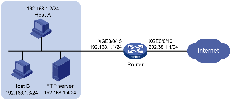
Requirements analysis
To allow external hosts to access the internal FTP server by using a public IP address, configure NAT Server on the interface connected to the external network.
To allow internal hosts to access the internal FTP server by using a public IP address, perform the following tasks:
· Enable NAT hairpin on the interface connected to the internal network.
· Configure outbound NAT on the interface where the NAT server mapping is configured. The destination address is translated by matching the NAT server mapping. The source address is translated by matching the outbound NAT.
Procedure
# Specify IP addresses for the interfaces on the router. (Details not shown.)
# Configure a QoS policy on the router to redirect traffic that needs NAT to the service card. (Details not shown.)
# Configure ACL 2000 to identify packets from subnet 192.168.1.0/24.
<Router> system-view
[Router] acl basic 2000
[Router-acl-ipv4-basic-2000] rule permit source 192.168.1.0 0.0.0.255
[Router-acl-ipv4-basic-2000] quit
# Configure a NAT server mapping on Ten-GigabitEthernet 0/0/16 to map the IP address of the FTP server to a public address, allowing external users to access the internal FTP server.
[Router] interface ten-gigabitethernet 0/0/16
[Router-Ten-GigabitEthernet0/0/16] nat server protocol tcp global 202.38.1.2 inside 192.168.1.4 ftp
# Enable outbound NAT with Easy IP on Ten-GigabitEthernet 0/0/16 so that NAT translates the source addresses of the packets from internal hosts into the IP address of Ten-GigabitEthernet 0/0/16.
[Router-Ten-GigabitEthernet0/0/16] nat outbound 2000
# Enable NAT hairpin on Ten-GigabitEthernet 0/0/15.
[Router] interface ten-gigabitethernet 0/0/15
[Router-Ten-GigabitEthernet0/0/15] nat hairpin enable
[Router-Ten-GigabitEthernet0/0/15] quit
Verifying the configuration
# Verify that both internal and external hosts can access the internal FTP server through the public address. (Details not shown.)
# Display all NAT configuration and statistics.
[Router]display nat all
NAT hardware mode : Disabled
NAT outbound information:
Totally 1 NAT outbound rules.
Interface: Ten-GigabitEthernet0/0/16
ACL: 2000 Address group: --- Port-preserved: N
NO-PAT: N Reversible: N
Config status: Active
NAT internal server information:
Totally 1 internal servers.
Interface: Ten-GigabitEthernet0/0/16
Protocol: 6(TCP)
Global IP/port: 202.38.1.2/21
Local IP/port : 192.168.1.4/21
Config status : Active
NAT logging:
Log enable : Disabled
Log format user-mac : Disabled
Flow-begin : Disabled
Flow-end : Disabled
Flow-active : Disabled
Port-block-assign : Disabled
Port-block-withdraw : Disabled
Port-alloc-fail : Disabled
Port-block-alloc-fail : Disabled
Port-usage : Disabled
Port-block-usage : Enabled(Threshold: 90%)
Address-group-usage : Enabled(Threshold: 90%)
Bandwidth-usage : Enabled(Threshold: 90%)
NAT hairpinning:
Totally 1 interfaces enabled with NAT hairpinning.
Interface: Ten-GigabitEthernet0/0/15
Config status: Active
NAT mapping behavior:
Mapping mode : Connection-Dependent
ACL : ---
Config status: Active
NAT ALG:
DNS : Disabled
FTP : Enabled
H323 : Disabled
ICMP-ERROR : Enabled
ILS : Disabled
MGCP : Disabled
NBT : Disabled
PPTP : Disabled
RTSP : Enabled
RSH : Disabled
SCCP : Disabled
SIP : Disabled
SQLNET : Disabled
TFTP : Disabled
XDMCP : Disabled
NAT Agency ALG:
FTP : Enabled
ICMP-ERROR : Enabled
SIP : Disabled
NAT extended port block report to RADIUS: Disabled
NAT abnormal-cu-connection auto-renew-lease: Disabled
NAT hardware ignore-flowredirect-method : Disabled
# Display NAT session information generated when Host A accesses the FTP server.
[Router] display nat session verbose
Initiator:
Source IP/port: 192.168.1.2/1694
Destination IP/port: 202.38.1.2/21
DS-Lite tunnel peer: -
VPN instance/VLAN ID/VLL ID: -/-/-
Protocol: TCP(6)
Inbound interface: Ten-GigabitEthernet0/0/15
Responder:
Source IP/port: 192.168.1.4/21
Destination IP/port: 202.38.1.1/1025
DS-Lite tunnel peer: -
VPN instance/VLAN ID/VLL ID: -/-/-
Protocol: TCP(6)
Inbound interface: Ten-GigabitEthernet0/0/15
State: TCP_ESTABLISHED
Application: FTP
Role: -
Failover group ID: -
Start time: 2012-08-15 14:53:29 TTL: 3597s
Initiator->Responder: 7 packets 308 bytes
Responder->Initiator: 5 packets 312 bytes
Example: Configuring load sharing NAT Server
Network configuration
As shown in Figure 22, three FTP servers are in the intranet to provide FTP services for external users. Configure NAT so that these external users use the address 202.38.1.1/16 to access the servers and the three FTP servers implement load sharing.

Procedure
# Specify IP addresses for the interfaces on the router. (Details not shown.)
# Configure ACL 2001 to identify packets from subnet 10.110.10.0/24.
<Router> system-view
[Router] acl basic 2001
[Router-acl-ipv4-basic-2001] rule permit source 10.110.10.0 0.0.0.255
[Router-acl-ipv4-basic-2001] quit
# Configure a QoS policy to redirect packets matching ACL 2001 to the local card.
[Router] traffic classifier 1
[Router-classifier-1] if-match acl 2001
[Router-classifier-1] quit
[Router] traffic behavior 1
[Router-behavior-1] redirect local
[Router-behavior-1] quit
[Router] qos policy 1
[Router-qospolicy-1] classifier 1 behavior 1
[Router-qospolicy-1] quit
[Router] interface ten-gigabitethernet 0/0/15
[Router-Ten-GigabitEthernet0/0/15] qos apply policy 1 inbound
[Router-Ten-GigabitEthernet0/0/15] quit
# Create NAT Server group 0, and add members to the group.
[Router] nat server-group 0
[Router-nat-server-group-0] inside ip 10.110.10.1 port 21
[Router-nat-server-group-0] inside ip 10.110.10.2 port 21
[Router-nat-server-group-0] inside ip 10.110.10.3 port 21
[Router-nat-server-group-0] quit
# Associate NAT Server group 0 with Ten-GigabitEthernet 0/0/16 so that servers in the server group can provide FTP services.
[Router] interface ten-gigabitethernet 0/0/16
[Router-Ten-GigabitEthernet0/0/16] nat server protocol tcp global 202.38.1.1 ftp inside server-group 0
[Router-Ten-GigabitEthernet0/0/16] quit
Verifying the configuration
# Verify that external hosts can access the internal FTP server group. (Details not shown.)
# Display all NAT configuration and statistics.
[Router] display nat all
NAT hardware mode : Disabled
NAT server group information:
Totally 1 NAT server groups.
Group Number Inside IP Port Weight
0 10.110.10.1 21 100
10.110.10.2 21 100
10.110.10.3 21 100
NAT internal server information:
Totally 1 internal servers.
Interface: Ten-GigabitEthernet0/0/16
Protocol: 6(TCP)
Global IP/port: 202.38.1.1/21
Local IP/port : server group 0
10.110.10.1/21 (Connections: 1)
10.110.10.2/21 (Connections: 2)
10.110.10.3/21 (Connections: 2)
Config status : Active
NAT logging:
Log enable : Disabled
Log format user-mac : Disabled
Flow-begin : Disabled
Flow-end : Disabled
Flow-active : Disabled
Port-block-assign : Disabled
Port-block-withdraw : Disabled
Port-alloc-fail : Disabled
Port-block-alloc-fail : Disabled
Port-usage : Disabled
Port-block-usage : Enabled(Threshold: 90%)
Address-group-usage : Enabled(Threshold: 90%)
Bandwidth-usage : Enabled(Threshold: 90%)
NAT mapping behavior:
Mapping mode : Connection-Dependent
ACL : ---
Config status: Active
NAT ALG:
DNS : Disabled
FTP : Enabled
H323 : Disabled
ICMP-ERROR : Enabled
ILS : Disabled
MGCP : Disabled
NBT : Disabled
PPTP : Disabled
RTSP : Enabled
RSH : Disabled
SCCP : Disabled
SIP : Disabled
SQLNET : Disabled
TFTP : Disabled
XDMCP : Disabled
NAT Agency ALG:
FTP : Enabled
ICMP-ERROR : Enabled
SIP : Disabled
NAT extended port block report to RADIUS: Disabled
NAT abnormal-cu-connection auto-renew-lease: Disabled
NAT hardware ignore-flowredirect-method : Disabled
# Display NAT session information generated when external hosts access an internal FTP server.
[Router] display nat session verbose
Initiator:
Source IP/port: 200.1.1.10/53957
Destination IP/port: 202.38.1.1/21
DS-Lite tunnel peer: -
VPN instance/VLAN ID/VLL ID: -/-/-
Protocol: TCP(6)
Inbound interface: Ten-GigabitEthernet0/0/16
Responder:
Source IP/port: 10.110.10.3/21
Destination IP/port: 200.1.1.10/53957
DS-Lite tunnel peer: -
VPN instance/VLAN ID/VLL ID: -/-/-
Protocol: TCP(6)
Inbound interface: Ten-GigabitEthernet0/0/15
State: TCP_ESTABLISHED
Application: FTP
Role: -
Failover group ID: -
Start time: 2012-08-16 11:06:07 TTL: 26s
Initiator->Responder: 1 packets 60 bytes
Responder->Initiator: 2 packets 120 bytes
Total sessions found: 1
Example: Configuring NAT DNS mapping
Network configuration
As shown in Figure 23, the internal Web server at 10.110.10.1/16 and FTP server at 10.110.10.2/16 provide services for external user. The company has three public addresses 202.38.1.1 through 202.38.1.3. The DNS server at 202.38.1.4 is on the external network.
Configure NAT so that:
· The public IP address 202.38.1.2 is used by external users to access the Web and FTP servers.
· External users can use the public address or domain name of internal servers to access them.
· Internal users can access the internal servers by using their domain names.

Requirements analysis
To meet the network requirements, perform the following tasks:
· Configure NAT Server by mapping the public IP addresses and port numbers of the internal servers to a public address and port numbers so that external users can access the internal servers.
· Configure NAT DNS mapping and ALG so that the public IP address of the internal server in the payload of the DNS response packet can be translated to the private IP address.
Procedure
# Specify IP addresses for the interfaces on the router. (Details not shown.)
# Configure ACL 2001 to identify packets from subnet 10.110.10.0/24.
<Router> system-view
[Router] acl basic 2001
[Router-acl-ipv4-basic-2001] rule permit source 10.110.10.0 0.0.0.255
[Router-acl-ipv4-basic-2001] quit
# Configure a QoS policy to redirect packets matching ACL 2001 to the local card.
[Router] traffic classifier 1
[Router-classifier-1] if-match acl 2001
[Router-classifier-1] quit
[Router] traffic behavior 1
[Router-behavior-1] redirect local
[Router-behavior-1] quit
[Router] qos policy 1
[Router-qospolicy-1] classifier 1 behavior 1
[Router-qospolicy-1] quit
[Router] interface ten-gigabitethernet 0/0/15
[Router-Ten-GigabitEthernet0/0/15] qos apply policy 1 inbound
[Router-Ten-GigabitEthernet0/0/15] quit
# Enable NAT ALG for DNS.
[Router] nat alg dns
# Enter interface view of Ten-GigabitEthernet 0/0/16.
[Router] interface ten-gigabitethernet 0/0/16
# Configure NAT Server to allow external hosts to access the internal Web server by using the address 202.38.1.2.
[Router-Ten-GigabitEthernet0/0/16] nat server protocol tcp global 202.38.1.2 inside 10.110.10.1 http
# Configure NAT Server to allow external hosts to access the internal FTP server by using the address 202.38.1.2.
[Router-Ten-GigabitEthernet0/0/16] nat server protocol tcp global 202.38.1.2 inside 10.110.10.2 ftp
# Enable outbound NAT with Easy IP on Ten-GigabitEthernet 0/0/16.
[Router-Ten-GigabitEthernet0/0/16] nat outbound
# Configure two NAT DNS mapping entries by mapping the domain name www.example.com of the Web server to 202.38.1.2, and ftp.example.com of the FTP server to 202.38.1.2.
[Router] nat dns-map domain www.example.com protocol tcp ip 202.38.1.2 port http
[Router] nat dns-map domain ftp.example.com protocol tcp ip 202.38.1.2 port ftp
Verifying the configuration
# Verify that both internal and external hosts can access the internal servers by using domain names. (Details not shown.)
# Display all NAT configuration and statistics.
[Router] display nat all
NAT hardware mode : Disabled
NAT outbound information:
Totally 1 NAT outbound rules.
Interface: Ten-GigabitEthernet0/0/16
ACL: --- Address group: --- Port-preserved: N
NO-PAT: N Reversible: N
Config status: Active
NAT internal server information:
Totally 2 internal servers.
Interface: Ten-GigabitEthernet0/0/16
Protocol: 6(TCP)
Global IP/port: 202.38.1.2/21
Local IP/port : 10.110.10.2/21
Config status : Active
Interface: Ten-GigabitEthernet0/0/16
Protocol: 6(TCP)
Global IP/port: 202.38.1.2/80
Local IP/port : 10.110.10.1/80
Config status : Active
NAT DNS mapping information:
Totally 2 NAT DNS mappings.
Domain name: ftp.example.com
Global IP : 202.38.1.2
Global port: 21
Protocol : TCP(6)
Config status: Active
Domain name: www.example.com
Global IP : 202.38.1.2
Global port: 80
Protocol : TCP(6)
Config status: Active
NAT logging:
Log enable : Disabled
Log format user-mac : Disabled
Flow-begin : Disabled
Flow-end : Disabled
Flow-active : Disabled
Port-block-assign : Disabled
Port-block-withdraw : Disabled
Port-alloc-fail : Disabled
Port-block-alloc-fail : Disabled
Port-usage : Disabled
Port-block-usage : Enabled(Threshold: 90%)
Address-group-usage : Enabled(Threshold: 90%)
Bandwidth-usage : Enabled(Threshold: 90%)
NAT mapping behavior:
Mapping mode : Connection-Dependent
ACL : ---
Config status: Active
NAT ALG:
DNS : Enabled
FTP : Enabled
H323 : Disabled
ICMP-ERROR : Enabled
ILS : Disabled
MGCP : Disabled
NBT : Disabled
PPTP : Disabled
RTSP : Enabled
RSH : Disabled
SCCP : Disabled
SIP : Disabled
SQLNET : Disabled
TFTP : Disabled
XDMCP : Disabled
NAT Agency ALG:
FTP : Enabled
ICMP-ERROR : Enabled
SIP : Disabled
NAT extended port block report to RADIUS: Disabled
NAT abnormal-cu-connection auto-renew-lease: Disabled
NAT hardware ignore-flowredirect-method : Disabled
Example: Configuring NAT log export to the information center
Network configuration
As shown in Figure 24, configure NAT on the device for the internal host to access the Internet. Configure NAT logging on the device and configure the device to export the NAT logs to the information center. The NAT logs in the information center are used for monitoring the internal host.

Prerequisites
Assign IP addresses to interfaces on the device and make sure the device and the host can reach each other.
Procedure
# Specify the information center as the destination for flow log export.
<Device> system-view
[Device] userlog flow syslog
# Enable NAT logging.
[Device] nat log enable
# Enable logging for NAT session establishment events.
[Device] nat log flow-begin
# Enable logging for NAT session removal events.
[Device] nat log flow-end
# Enable logging for active NAT flows and set the logging interval to 10 minutes.
[Device] nat log flow-active 10
[Device] quit
Verifying the configuration
# Display the internal host's access records in the log buffer.
Directory of cf:/
38 -rw- 141 Aug 07 2015 17:54:43 ifindex.dat
39 drw- - May 20 2015 14:36:20 logfile
249852 KB total (232072 KB free)
File system type of cf: FAT32
<Device> cd logfile
<Device> dir
<Device> more logfile.log
…
%Aug 10 20:06:30:182 2015 Device NAT/6/NAT_FLOW: Protocol(1001)=ICMP;SrcIPAd
dr(1003)=10.110.10.8;SrcPort(1004)=259;NatSrcIPAddr(1005)=202.38.1.100;NatSrcPor
t(1006)=0;DstIPAddr(1007)=202.38.1.2;DstPort(1008)=2048;NatDstIPAddr(1009)=202.3
8.1.2;NatDstPort(1010)=259;InitPktCount(1044)=0;InitByteCount(1046)=0;RplyPktCou
nt(1045)=0;RplyByteCount(1047)=0;RcvVPNInstance(1042)=;SndVPNInstance(1043)=;Rcv
DSLiteTunnelPeer(1040)=;SndDSLiteTunnelPeer(1041)=;BeginTime_e(1013)=08102015200
630; EndTime_e(1014)=08102015200700;Event(1048)=(8)Session created;
…
Table 1 Command output
|
Field |
Description |
|
Protocol(1001)=ICMP |
Protocol type. |
|
SrcIPAddr(1003)=10.110.10.8 |
Source IP address before NAT. |
|
SrcPort(1004)=259 |
Source TCP or UDP port before NAT. |
|
NatSrcIPAddr(1005)=202.38.1.100 |
Source IP address after NAT. |
|
NatSrcPort(1006)=0 |
Source TCP or UDP port after NAT. |
|
DstIPAddr(1007)=202.38.1.2 |
Destination IP address before NAT. |
|
DstPort(1008)=2048 |
Destination TCP or UDP port before NAT. |
|
NatDstIPAddr(1009)=202.38.1.2 |
Destination IP address after NAT. |
|
NatDstPort(1010)=259 |
Destination TCP or UDP port after NAT. |
|
BeginTime_e(1013)=08102015200630 |
Start time of the flow, in the MMDDYYYYHHMMSS format. |
|
EndTime_e(1014)=08102015200700 |
End time of the flow, in the MMDDYYYYHHMMSS format. |
Example: Configuring NAT log export to the log server
Network configuration
As shown in Figure 25, configure the device to export the NAT logs to the log server. The NAT logs in the log server are used for monitoring the internal user.
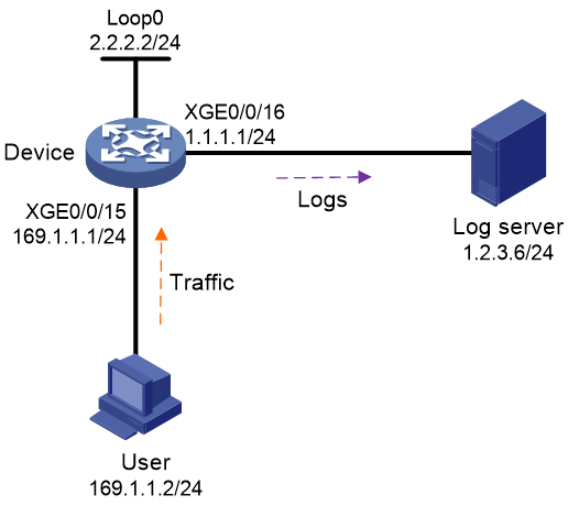
Prerequisites
Assign IP addresses to interfaces on the device. Make sure the routes between the device and the user and between the device and the log server are reachable.
Procedure
# Enable NAT logging.
<Device> system-view
[Device] nat log enable
# Enable logging for NAT session establishment events.
[Device] nat log flow-begin
# Enable logging for NAT session removal events.
[Device] nat log flow-end
# Enable logging for active NAT flows and set the logging interval to 10 minutes.
[Device] nat log flow-active 10
# Set the flow log version to 3.0.
[Device] userlog flow export version 3
# Export flow log entries to port 2000 on the log host at 1.2.3.6.
[Device] userlog flow export host 1.2.3.6 port 2000
# Specify 2.2.2.2 as the source IP address for flow log packets.
[Device] userlog flow export source-ip 2.2.2.2
[Device] quit
Verifying the configuration
# Display the flow log configuration and statistics.
<Device> display userlog export
Flow:
Export flow log as UDP Packet.
Version: 3.0
Source ipv4 address: 2.2.2.2
Source ipv6 address:
Log load balance function: Disabled
Local time stamp: Disabled
Number of log hosts: 1
Log host 1:
Host/Port: 1.2.3.6/2000
