07-H3C IMC UAM Binding an 802.1X User with the Access Device Configuration Examples-book.pdf(741.44 KB)
- Released At: 05-07-2024
- Page Views:
- Downloads:
- Table of Contents
- Related Documents
-
|
H3C IMC UAM |
|
Binding an 802.1X User with the Access Device Configuration Examples |
|
|
Software version: IMC UAM 7.2 (E0403)
|
Copyright © 2016 Hangzhou H3C Technologies Co., Ltd. All rights reserved. No part of this manual may be reproduced or transmitted in any form or by any means without prior written consent of Hangzhou H3C Technologies Co., Ltd. The information in this document is subject to change without notice. |
|
Contents
Example: Binding an access user with the IP address and VLAN of a switch
Configuring the switch as an access device
Triggering 802.1X authentication
Viewing the user binding information
Reauthenticating the access user with another IP address
Introduction
The examples apply to enterprise and campus networks that require user access control.
Prerequisites
Make sure the access device supports 802.1X.
Example: Binding an access user with the IP address and VLAN of a switch
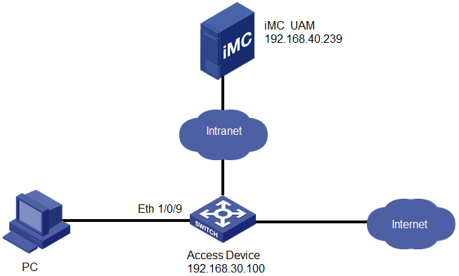
Network configuration
As shown in Figure 1, UAM is deployed on the server at 192.168.40.239. A user attempts to access the network by using an 802.1X connection in the iNode PC client.
The switch manages the 802.1X user in an ISP domain named h3c and includes the domain name in the user names that it sends for authentication.
The user accesses the network by using an account named test.
· Set the shared keys for secure RADIUS communication to iMC123, set the authentication port to 1812, and set the accounting port to 1813.
· Configure UAM to bind the access user with the access device and a VLAN ID.
Software versions used
This configuration example was created and verified on the following platforms:
· IMC UAM 7.2 (E0403).
· H3C S3600V2-28TP-EI Release 2103.
· iNode PC 7.2 (E0402).
Restrictions and guidelines
When you configure the access device binding, follow these restrictions and guidelines:
· UAM must provide both authentication and accounting services. Do not use a second server (other than the UAM server) to provide accounting.
· Make sure the parameters you configure for the access device in UAM (for example, the authentication and accounting ports and shared key) are the same as those in the CLI configuration on the switch.
· If you want to select the switch from the resource pool as an access device, make sure it is already added to the IMC platform, either manually or through auto discovery.
· Configure a service suffix for the 802.1X user depending on the authentication domain and username format settings on the switch, as shown in Table 1.
Table 1 Service suffix
|
User name in iNode |
Authentication domain on the switch |
Username format command on the switch |
Service suffix in UAM |
|
test@h3c |
h3c |
user-name-format with-domain |
h3c |
|
user-name-format without-domain |
No suffix |
Configuring UAM
Configuring the switch as an access device
1. Click the User tab.
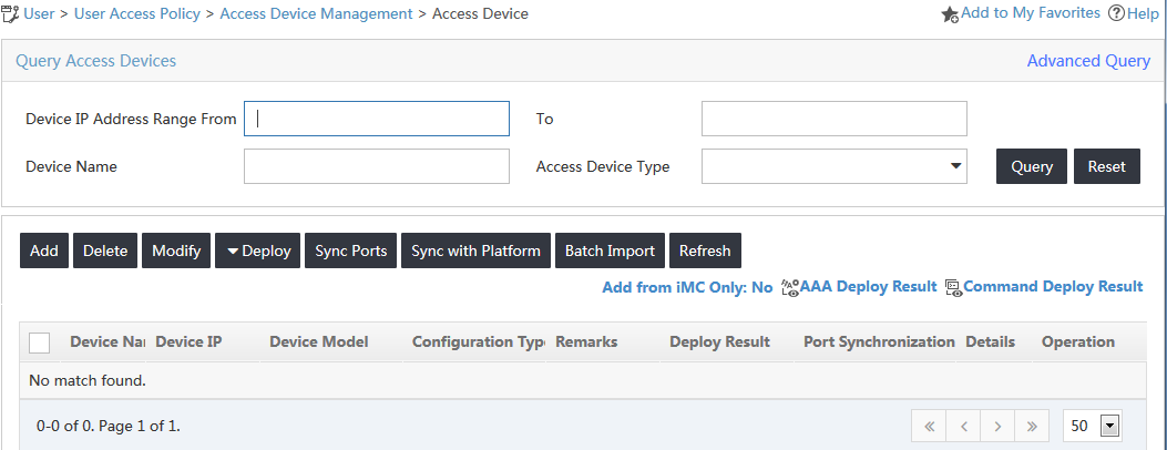
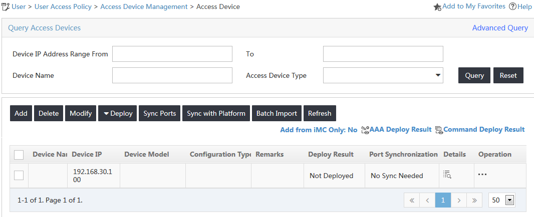
2. From the navigation tree, select User Access Policy > Access Device Management > Access Device.
The Access Device page opens, as shown in Figure 2.
Figure 2 Accessing the Access Device page
3. Click Add.
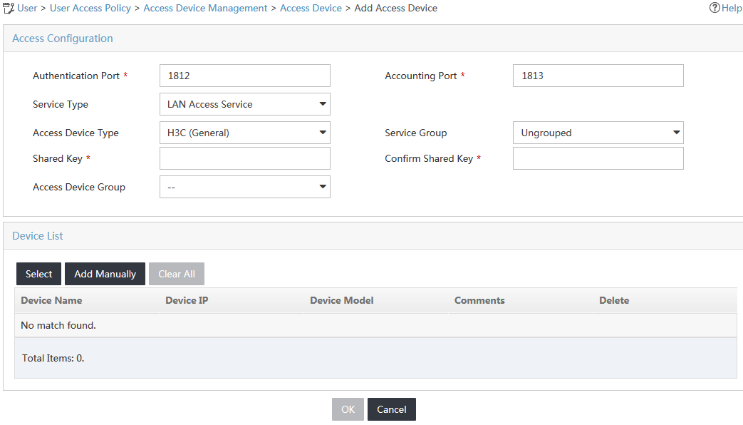
4. Configure access information for the access device, as shown in Figure 3:
a. In the Access Configuration area, enter iMC123 in the Shared Key and Confirm Shared Key fields.
b. Use the default values for other parameters.
Figure 3 Adding an access device
5. Add the switch to UAM as an access device.
You can add a device to UAM either manually or by selecting the device from the IMC platform. This example uses the Add Manually option.
To manually add the switch to UAM:
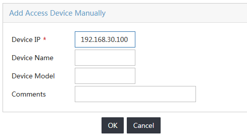
a. Click Add Manually.
b. On the Add Access Device Manually window, enter the IP address of the switch in the Device IP field, as shown in Figure 4.
Figure 4 Adding access device manually
a. Click OK.
The Add Access Device Manually window closes.
b. On the Add Access Device page, click OK.
c. On the results page, click Back to Access Device List.
The new access device is displayed in the access device list, as shown in Figure 5.
Figure 5 Viewing the switch on the access device list
Configuring an access policy
1. Click the User tab.
2. From the navigation tree, select User Access Policy > Access Policy.
3. On the Access Policy list, click Add.
The Add Access Policy page opens.
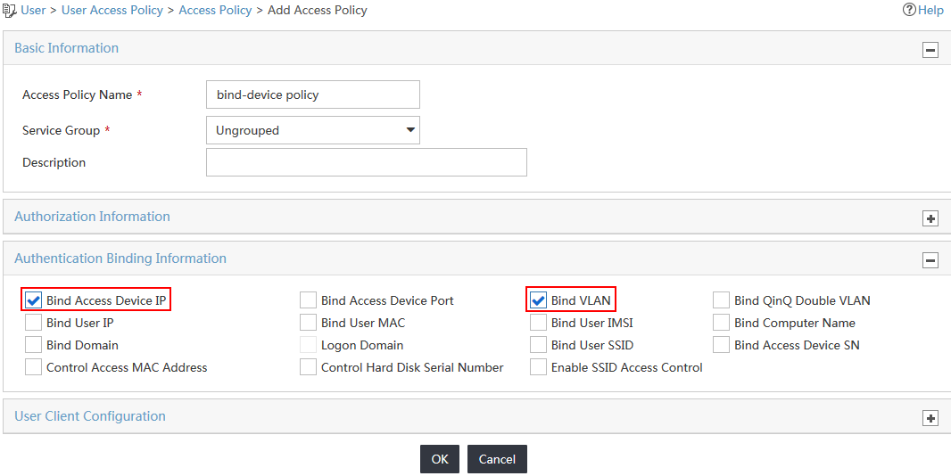
4. Configure access policy parameters, as shown in Figure 6:
a. In the Basic Information area, enter bind-device policy in the Access Policy Name field and use the default values for other parameters.
b. In the Authentication Binding Information area, select the Bind Access Device IP and Bind VLAN options. Leave other options unselected.
c. Use the default values for other areas.
Figure 6 Adding an access policy
5. Click OK.
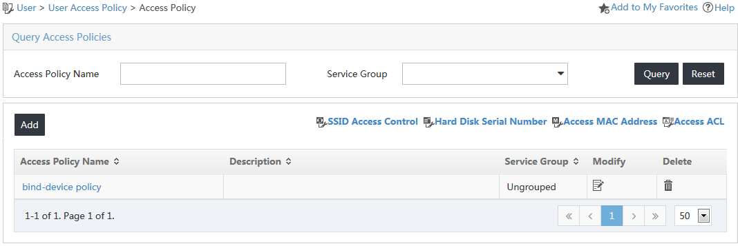
The new access policy is displayed in the access policy list, as shown in Figure 7.
Figure 7 Viewing the new access policy on the access policy list
Configuring an access service
1. Click the User tab.
2. From the navigation tree, select User Access Policy > Access Service.
3. On the Access Service list, click Add.
The Add Access Service page opens.
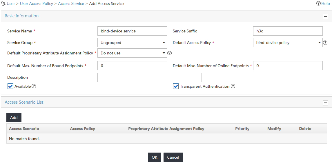
4. Configure basic information for the access service, as shown in Figure 8:
a. Enter bind-device service in the Service Name field.
b. Enter h3c in the Service Suffix field.
c. Select bind-device policy from the Default Access Policy list.
d. Use the default values for other parameters.
Figure 8 Adding an access service
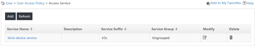
5. Click OK.
The new access service is displayed in the access service list, as shown in Figure 9.
Figure 9 Viewing the new access service
Configuring an access user
1. Click the User tab.
2. From the navigation tree, select Access User > All Access Users.
3. On the Access User list, click Add.
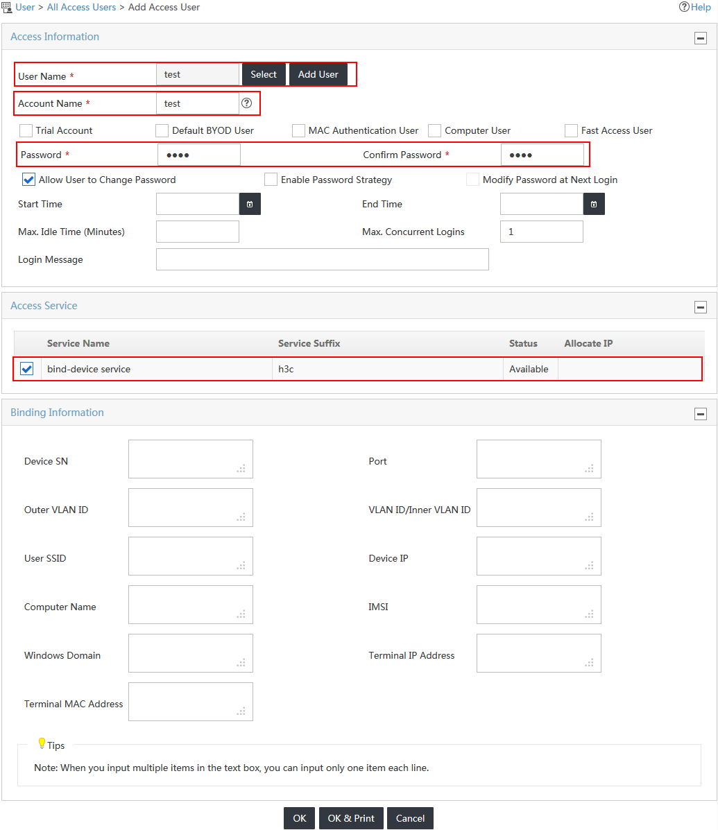
The Add Access User page opens, as shown in Figure 10.
Figure 10 Accessing the Adding Access User page
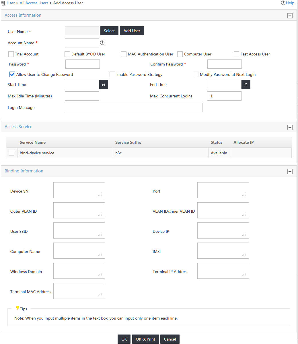
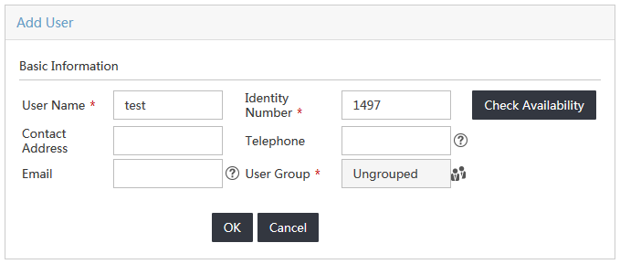
4. In the User Name field, click Select to select an existing user account from the IMC platform, or click Add User to add a new IMC platform user.
This example uses the Add User option. In the User Name field, enter test, as shown in Figure 11.
Figure 11 Adding a new IMC platform user
5. Configure the password and service for the access user, as shown in Figure 12:
a. Enter 1234 in the Password and Confirm Password fields.
b. Select the service named bind-device service in the Access Service field.
Figure 12 Adding an access user
6. Use the default values for other parameters.
7. Click OK.
The new access user is displayed in the access user list. Click test to view detailed information, as shown in Figure 13.
Figure 13 Viewing the new access user

The access device binding information for the access device is empty, as shown in Figure 14.
Configuring the switch
1. Configure a RADIUS scheme:
# Create a RADIUS scheme named devicebind.
<Device> system-view
[Device] radius scheme devicebind
# Configure UAM as the primary RADIUS authentication and accounting server. Set the RADIUS authentication port to 1812, and set the accounting port to 1813.
[Device-radius-devicebind] primary authentication 192.168.40.239 1812
[Device-radius-devicebind] primary accounting 192.168.40.239 1813
# Configure the shared key to iMC123 to secure RADIUS authentication and accounting communication.
[Device-radius-devicebind] key authentication iMC123
[Device-radius-devicebind] key accounting iMC123
# Specify the source IP address for outgoing RADIUS packets.
[Device-radius-devicebind] nas-ip 192.168.30.100
# Specify the RADIUS server type as extended to support UAM.
[Device-radius-devicebind] server-type extended
# Configure the switch to include domain information from the user names it sends to the RADIUS server.
[Device-radius-devicebind] user-name-format with-domain
[Device-radius-devicebind] quit
2. Create an ISP domain:
# Create an ISP domain named h3c.
[Device] domain h3c
# Configure the switch to use the RADIUS scheme devicebind for LAN users.
[Device-isp-h3c] authentication lan-access radius-scheme devicebind
[Device-isp-h3c] authorization lan-access radius-scheme devicebind
[Device-isp-h3c] accounting lan-access radius-scheme devicebind
[Device-isp-h3c] quit
3. Configure 802.1X authentication:
# Enable 802.1X globally and on Ethernet 1/0/9. The 802.1X function takes effect on the interface only when 802.1X is enabled globally and on the interface.
[Device] dot1x
802.1X is enabled globally.
[Device] dot1x interface Ethernet 1/0/9
802.1X is enabled on port Ethernet 1/0/9.
# Configure the switch to perform EAP termination and to support all CHAP authentication methods for RADIUS communication.
[Device] dot1x authentication-method chap
Verifying the configuration
Triggering 802.1X authentication
1. On the iNode PC client, double-click My 802.1X Connection.
The 802.1X Authentication Connection window opens, as shown in Figure 15.
Figure 15 802.1X authentication connection
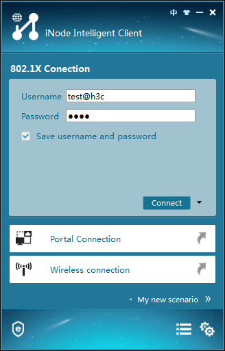
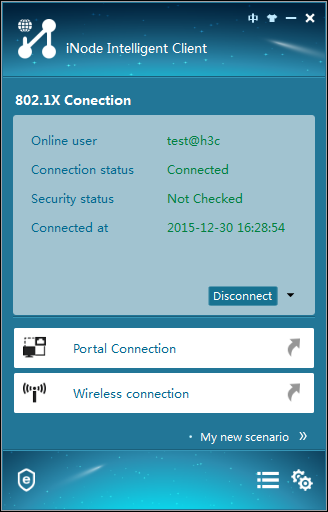
2. Enter the user name test@h3c and the password 1234, and then click Connect.
The authentication process starts, as shown in Figure 16. You can view the authentication messages in the Authentication Information area.
Figure 16 Authentication information
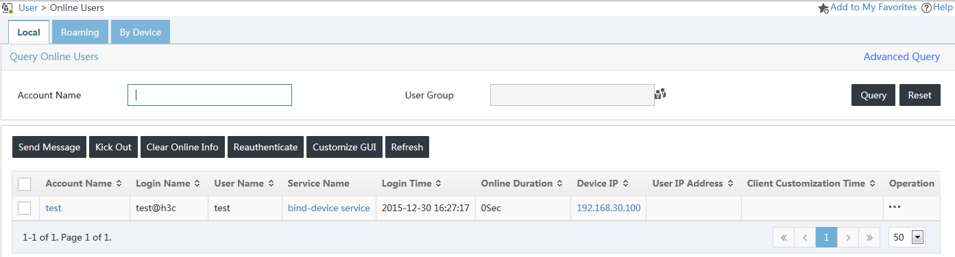
Viewing online users
After the user passes authentication, you can view it as an online user in UAM:
1. Click the User tab.
2. From the navigation tree, select Access User Management > Online Users.
The user named test is in the online user list, as shown in Figure 17.
Figure 17 Viewing the online user
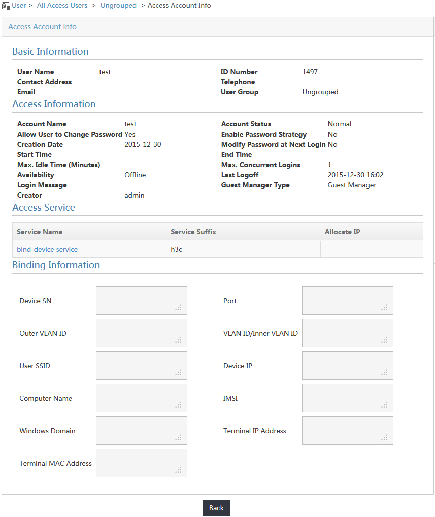
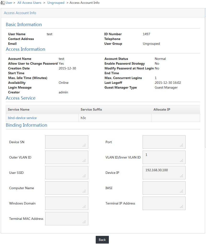
Viewing the user binding information
When the user passes authentication, the IP address of the access device and the VLAN to which the access device belongs are automatically bound to the user. VLAN 1 is the default VLAN on the access device.
On the online user list, click the account name test to display detailed information about the user. You can view the IP address of the access device and the bound VLAN ID in the Binding Information area, as shown in Figure 18.
Figure 18 Viewing the access account information
Reauthenticating the access user with another IP address
If you modify the access device IP address binding or the VLAN ID binding, the access user will not pass authentication. This example uses modifying the access device IP address binding.
1. Access the access user list page, as shown in Figure 19.
Figure 19 Accessing the access user list page
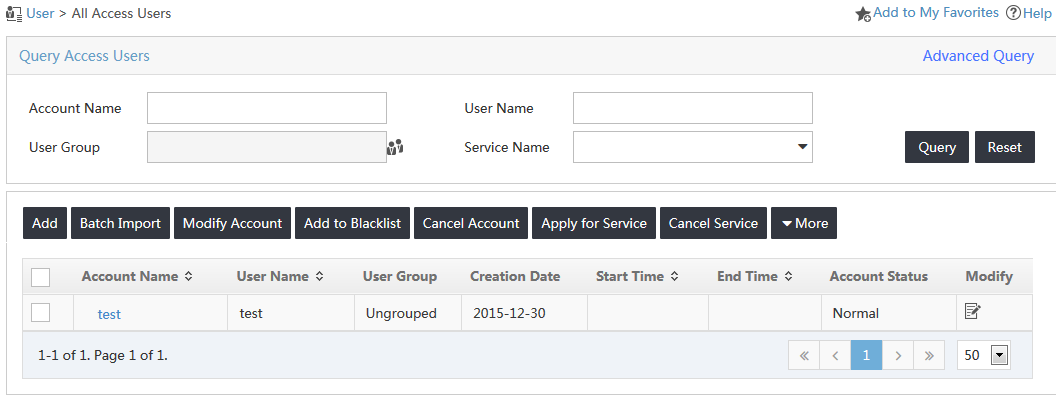
2. Click the Modify icon ![]() for
the access user named test.
for
the access user named test.
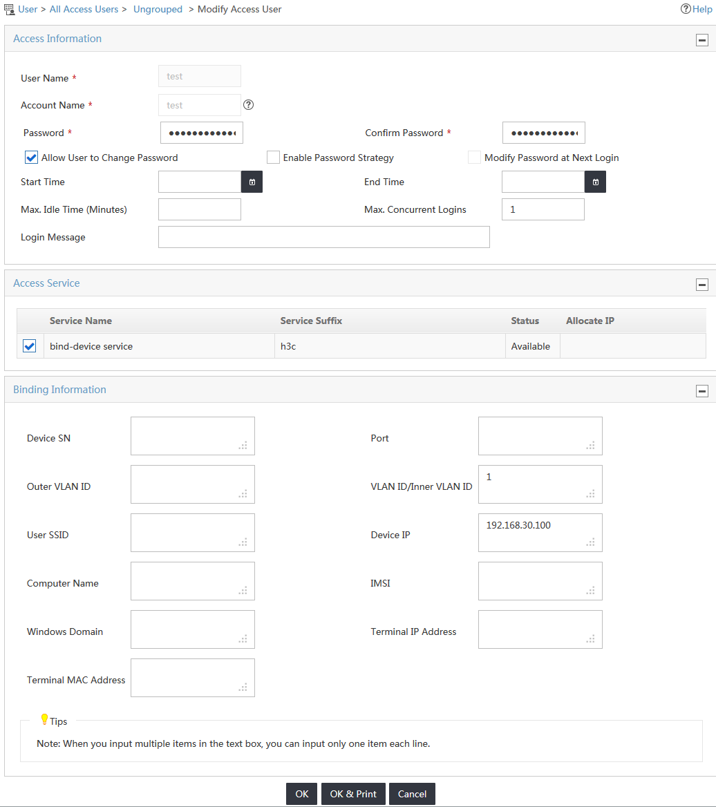
The Modify Access User page opens, as shown in Figure 20.
Figure 20 Accessing the Modify Access User page
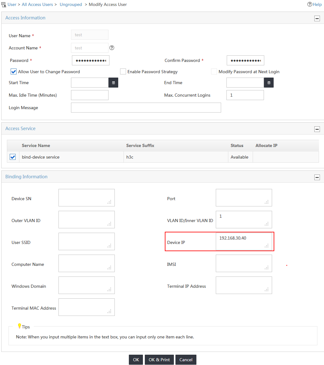
3. Change the IP address of the access device to another IP address, as shown in Figure 21.
This example uses 192.168.30.40.
Figure 21 Changing the access device IP address
4. Trigger 802.1X authentication in the iNode PC client.
An error message reports that the user cannot pass the access device IP address binding check, as shown in Figure 22.
Figure 22 802.1X authentication failure

