05-H3C IMC UAM Access Period Control with 802.1X Authentication Configuration Examples-book.pdf(695.62 KB)
- Released At: 05-07-2024
- Page Views:
- Downloads:
- Table of Contents
- Related Documents
-
|
H3C IMC UAM |
|
Access Period Control with 802.1X Authentication Configuration Examples |
|
|
Software version: IMC UAM 7.2 (E0403)
|
Copyright © 2016 Hangzhou H3C Technologies Co., Ltd. All rights reserved. No part of this manual may be reproduced or transmitted in any form or by any means without prior written consent of Hangzhou H3C Technologies Co., Ltd. The information in this document is subject to change without notice. |
|
Contents
Example: Configuring access period control with 802.1X authentication
Configuring the switch as an access device
Configuring an access period policy
Configuring an access user and assigning the service to the user
Triggering 802.1X authentication
Viewing the online user in UAM
Introduction
This document provides examples for configuring an access period policy in UAM for 802.1X users.
Prerequisites
Make sure the access device supports 802.1X.
Example: Configuring access period control with 802.1X authentication
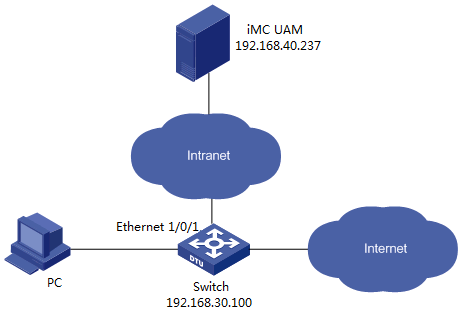
Network configuration
As shown in Figure 1, an 802.1X user connects to the network through the iNode client on a Windows PC. The username of the user's account is ice.
Configure UAM and the access switch to control network access for the user, as follows:
· Permit the user to access the network only from 09:00 to 18:00 on weekdays.
· Assign the user to ISP domain 391.
· Configure the switch to include the domain name in usernames that it sends for authentication.
· Set the shared key for secure RADIUS communication to movie, set the authentication port to 1812, and set the accounting port to 1813.
Software versions used
This example was created and verified on the following platforms:
· IMC UAM 7.2 (E0403)
· H3C S3600V2-28TP-EI Comware Software, Version 5.20, Release 2103
· iNode PC 7.2 (E0403)
Restrictions and guidelines
When you configure access period control for an 802.1X user, follow these restrictions and guidelines:
· Make sure the parameters configured in UAM for the access device (the switch) are the same as the settings on the switch.
· Configure a service suffix for the 802.1X user depending on the authentication domain and username format settings on the switch, as shown in Table 1.
Table 1 Determining the service suffix
|
Username in iNode |
Authentication domain on the switch |
Username format command on the switch |
Service suffix in UAM |
|
ice@391 |
391 |
user-name-format with-domain |
391 |
|
user-name-format without-domain |
No suffix |
Configuring UAM
Configuring the switch as an access device
1. Click the User tab.
2. From the navigation tree, select User Access Policy > Access Device Management > Access Device, as shown in Figure 2.
Figure 2 Accessing the Access Device page
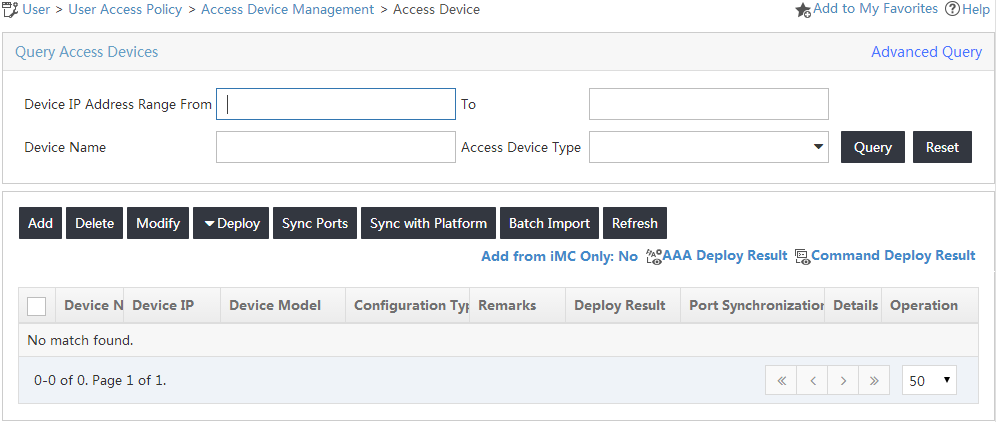
3. On the access device list, click Add.
The Add Access Device page opens, as shown in Figure 3.
Figure 3 Adding an access device

4. Add the switch to UAM as an access device.
You can add an access device by clicking Select or Add Manually in the Device List area. Follow these guidelines to configure the IP address of the access device:
¡ If you have configured the nas-ip command for the RADIUS scheme on the device, configure the NAS IP as the access device address in UAM.
¡ If you do not configure the nas-ip command for the RADIUS scheme, enter the IP address of the device's interface that connects to UAM for the access device.
The IP address cannot be modified if the device is selected from the IMC platform. It can be modified if the device is added manually.
To manually add an access device:
a. Click Add Manually in the Device List area.
The page for manually adding an access device opens.
b. Enter 192.168.30.100 in the Device IP field, as shown in Figure 4.
Figure 4 Manually adding an access device
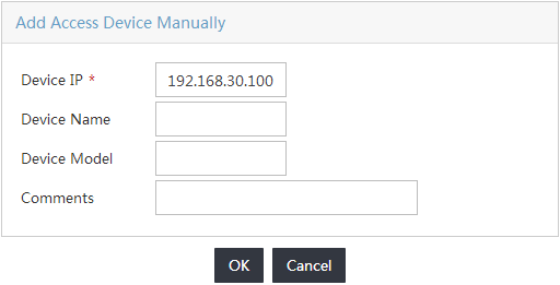
c. Click OK to return to the page for adding an access device.
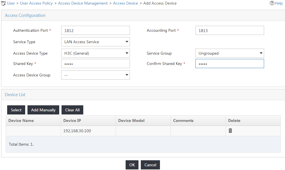
5. Configure access information for the access device, as shown in Figure 5:
a. Enter 1812 in the Authentication Port field and 1813 in the Accounting Port field.
b. Select H3C (General) from the Access Device Type list.
c. Enter movie in the Shared Key and Confirm Shared Key fields.
d. Use the default values for other parameters.
Figure 5 Adding an access device
6. Click OK.
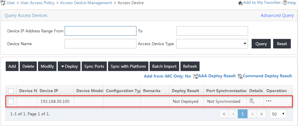
On the page that opens, click the Back to Access Device List link to view the added access device in the access device list, as shown in Figure 6.
Figure 6 Viewing the added access device
Configuring an access policy
1. Click the User tab.
2. From the navigation tree, select User Access Policy > Access Policy.
3. In the access policy list, click Add.
The Add Access Policy page opens.
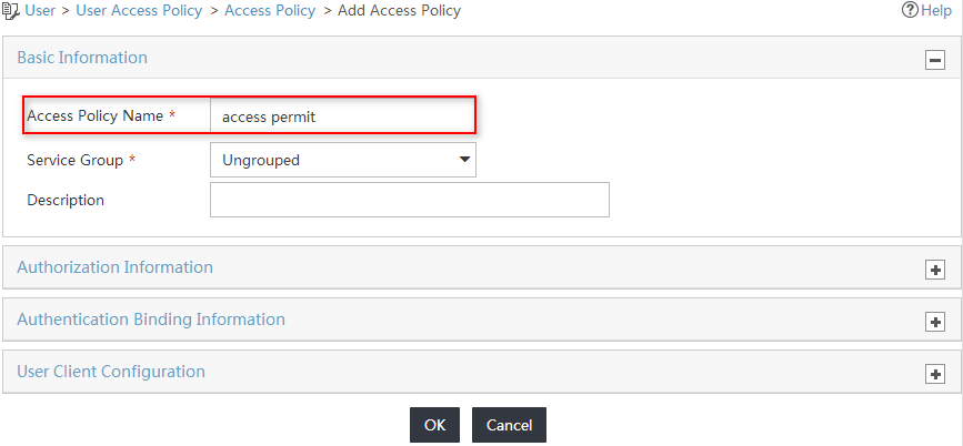
4. In the Basic Information area, enter access permit in the Access Policy Name field and use the default values for other parameters, as shown in Figure 7.
Figure 7 Adding an access policy
5. Click OK.
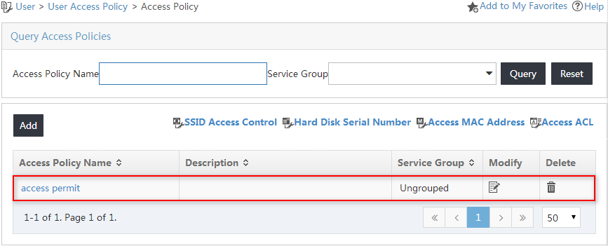
The new access policy is added to the access policy list, as shown in Figure 8.
Figure 8 Viewing the new access policy
Configuring an access period policy
1. Click the User tab.
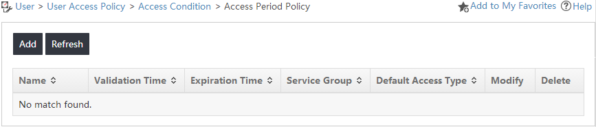
2. From the navigation tree, select User Access Policy > Access Condition > Access Period Policy, as shown in Figure 9.
Figure 9 Accessing the Access Period Policy page
3. On the access period policy list, click Add.
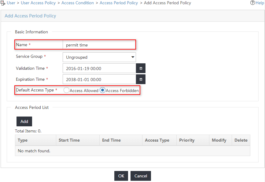
4. On the Add Access Period Policy page, configure basic information for the access period policy, as shown in Figure 10:
a. Enter permit time in the Name field.
b. Select Access Forbidden for the Default Access Type field.
c. Use the default values for other parameters.
Figure 10 Adding an access period policy
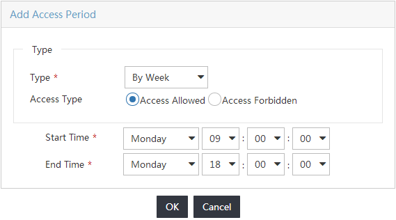
5. In the Access Period List area, click Add and configure the time periods to permit network access, as shown in Figure 11:
a. Select By Week from the Type list.
b. Select Access Allowed from the Access Type list.
c. Select the start time Monday 09:00:00 and the end time Monday 18:00:00.
d. Click OK.
e. Repeat the previous steps to configure the time period 09:00:00 to 18:00:00 for Tuesday through Friday.
Figure 11 Adding an access period
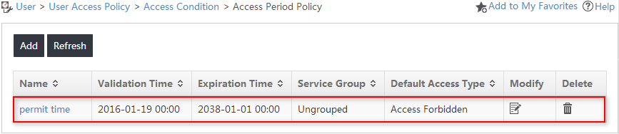
6. Click OK.
The new access period policy is added to the access period policy list, as shown in Figure 12.
Figure 12 Viewing the new access period policy
Configuring an access service
1. Click the User tab.
2. From the navigation tree, select User Access Policy > Access Service.
3. On the access service list, click Add.
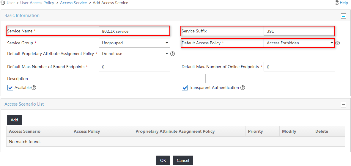
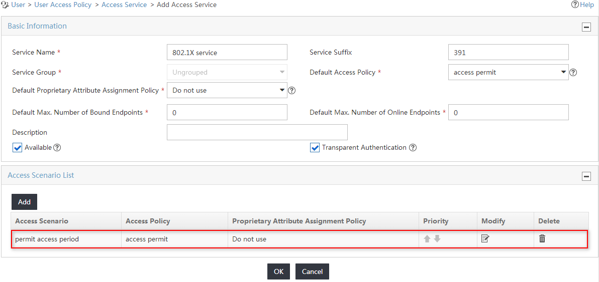
4. On the Add Access Service page, configure basic information for the access service to be added, as shown in Figure 13:
a. Enter 802.1X service in the Service Name field.
b. Enter 391 in the Service Suffix field.
c. Select Access Forbidden from the Default Access Policy list.
d. Use the default values for other parameters.
Figure 13 Adding an access service
5. In the Access Scenario List area, click Add.
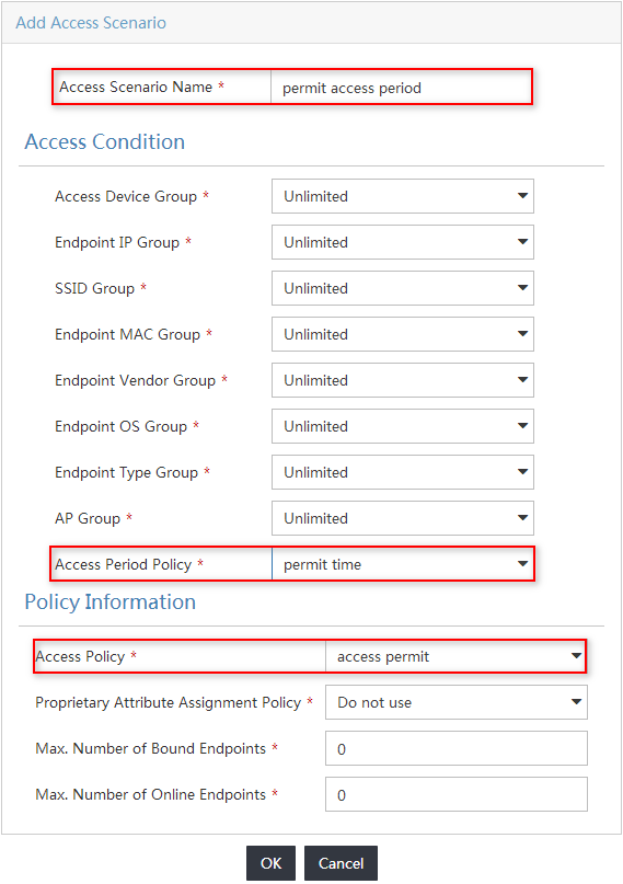
6. On the Add Access Scenario page, configure basic information for the access service to be added, as shown in Figure 14:
a. Enter permit access period in the Access Scenario Name field.
b. Select permit time from the Access Period Policy list.
c. Select access permit from the Access Policy list.
d. Use the default values for other parameters.
Figure 14 Adding an access scenario
7. Click OK.
The new access scenario is added to the access scenario list, as shown in Figure 15.
Figure 15 Viewing the new access scenario
8. Click OK on the Add Access Service page.
The new access service is added to the access service list, as shown in Figure 16.
Figure 16 Viewing the new access service

Configuring an access user and assigning the service to the user
1. Click the User tab.
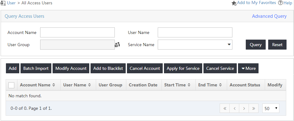
2. From the navigation tree, select Access User > All Access Users.
3. On the access user list, click Add, as shown in Figure 17.
Figure 17 Adding an access user
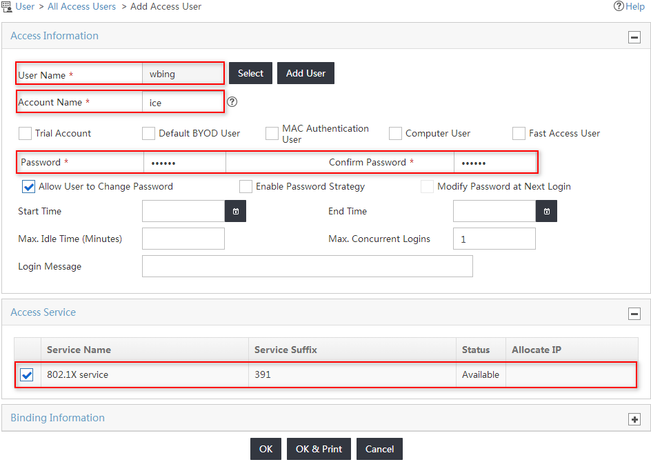
4. On the Add Access User page, configure the basic parameters for the access user, as shown in Figure 18:
a. In the User Name field, configure an IMC platform user to be associated with the access user.
You can either select an existing user account from the IMC platform or add a new IMC platform user.
This example uses the Add User option. On the Add User page, enter wbing in the User Name field, enter 0128 in the Identity Number field, and click OK.
b. Enter ice in the Account Name field.
c. Enter iMC123 in the Password and Confirm Password fields.
d. Select the service named 802.1X service in the Access Service area.
e. Use the default values for other parameters.
Figure 18 Adding an access user
5. Click OK.
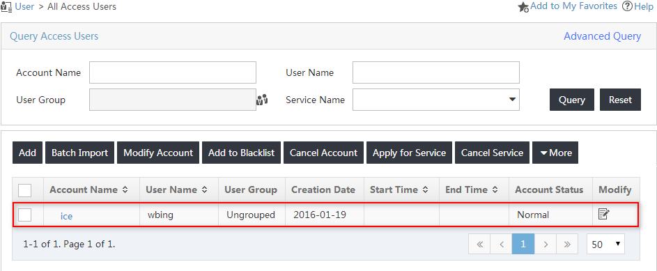
The new access user is added to the access user list, as shown in Figure 19.
Figure 19 Viewing the new access user
Configuring the switch
1. Configure a RADIUS scheme:
# Create a RADIUS scheme named 1xallpermit.
<Device> system-view
[Device] radius scheme 1xallpermit
# Configure UAM as the primary RADIUS authentication and accounting server. Set the RADIUS authentication port to 1812, and set the accounting port to 1813.
[Device-radius-1xallpermit] primary authentication 192.168.40.237 1812
[Device-radius-1xallpermit] primary accounting 192.168.40.237 1813
# Configure the shared key to movie to secure RADIUS authentication and accounting communication.
[Device-radius-1xallpermit] key authentication movie
[Device-radius-1xallpermit] key accounting movie
# Specify the RADIUS server type as extended to support UAM.
[Device-radius-1xallpermit] server-type extended
# Configure the switch to include domain information in the user names that are sent to the RADIUS server.
[Device-radius-1xallpermit] user-name-format with-domain
[Device-radius-1xallpermit] quit
2. Create an ISP domain:
# Create an ISP domain named 391.
[Device] domain 391
# Configure the switch to use the RADIUS scheme 1xallpermit for 802.1X users.
[Device-isp-391] authentication lan-access radius-scheme 1xallpermit
[Device-isp-391] authorization lan-access radius-scheme 1xallpermit
[Device-isp-391] accounting lan-access radius-scheme 1xallpermit
[Device-isp-391] quit
3. Configure 802.1X authentication:
# Enable 802.1X globally and on Ethernet 1/0/1. The 802.1X function takes effect on the interface only when 802.1X is enabled globally and on the interface.
[Device] dot1x
[Device] dot1x interface ethernet 1/0/1
# Configure the switch to perform EAP termination and to support all CHAP authentication methods for RADIUS communication.
[Device] dot1x authentication-method chap
Verifying the configuration
Triggering 802.1X authentication
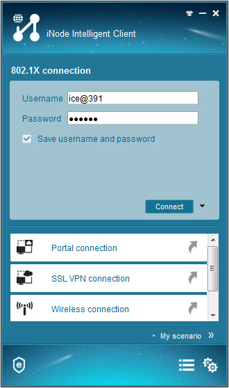
1. On the iNode client, click 802.1X Connection.
The 802.1X Connection window opens.
2. Enter the username and password, and click Connect, as shown in Figure 20.
The authentication process starts.
Figure 20 Triggering 802.1X authentication
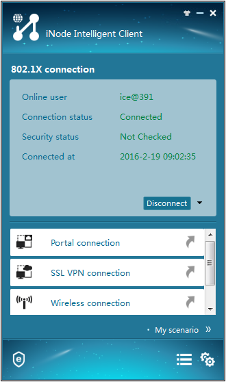
3. Verify that the user can pass 802.1X authentication from 09:00 to 18:00 on weekdays, as shown in Figure 21.
Figure 21 Viewing the authentication result
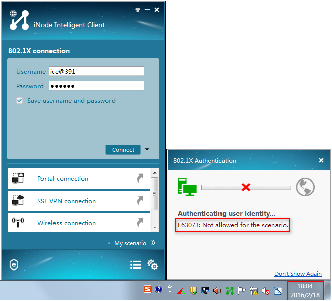
4. Verify that the user cannot pass 802.1X authentication on other time periods, as shown in Figure 22.
Figure 22 Viewing the authentication result
Viewing the online user in UAM
1. Click the User tab.
2. From the navigation tree, select Access User > Online Users.
3. Click the Local tab.
4. Verify that the user named ice has been added to the online user list, as shown in Figure 23.
Figure 23 Viewing the online user
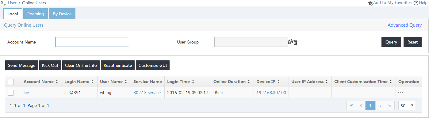
If the user is not online, select User Access Log > Auth Failure Log from the navigation tree to view the failure reason for user ice.
