- Table of Contents
- Related Documents
-
| Title | Size | Download |
|---|---|---|
| 07-Packet capture configuration | 133.82 KB |
Contents
Configuring the packet capture
Building a capture filter rule
Capture filter rule expressions
Building a display filter rule
Display filter rule expressions
Restrictions and guidelines: Packet capture
Configuring local packet capture
Configuring remote packet capture
Display and maintenance commands for packet capture
Packet capture configuration examples
Example: Configuring local packet capture
Example: Configuring remote packet capture
Configuring the packet capture
About packet capture
The packet capture feature captures incoming packets. It can display the captured packets in real time, or save the captured packets to a .pcap file for future analysis.
Packet capture modes
The device supports local packet capture and remote packet capture.
Local packet capture
Local packet capture saves captured packets to a remote file on an FTP server or to a local file, or displays captured packets on the terminal.
Remote packet capture
Remote packet capture sends captured packets to the Wireshark packet analyzer installed on a PC.
Before using remote packet capture, you must install the Wireshark software on a PC and connect the PC to the device.
Filter rule elements
Packet capture supports using a capture filter rule to filter packets to be captured or using a display filter rule to filter packets to be displayed.
A filter rule is represented by a filter expression. A filter expression contains a keyword string or multiple keyword strings that are connected by operators.
Keywords include the following types:
· Qualifiers—Fixed keyword strings. To use a qualifier, you must enter the qualifier literally as shown.
· Variables—Values assigned in the required format.
Operators include the following types:
· Logical operators—Perform logical operations, such as the AND operation.
· Arithmetic operators—Perform arithmetic operations, such as the ADD operation.
· Relational operators—Indicate the relation between keyword strings. For example, the = operator indicates equality.
For more information about capture and display filters, go to the following websites:
· http://wiki.wireshark.org/CaptureFilters
· http://wiki.wireshark.org/DisplayFilters
Building a capture filter rule
Capture filter rule keywords
Qualifiers
Table 1 Qualifiers for capture filter rules
|
Category |
Description |
Examples |
|
Protocol |
Matches a protocol. If you do not specify a protocol qualifier, the filter matches any supported protocols. |
· arp—Matches ARP. · icmp—Matches ICMP. · ip—Matches IPv4. · ip6—Matches IPv6. · tcp—Matches TCP. · udp—Matches UDP. |
|
Direction |
Matches packets based on its source or destination location (an IP address or port number). If you do not specify a direction qualifier, the src or dst qualifier applies. For example, port 23 is equivalent to src or dst port 23. |
· src—Matches the source IP address field. · dst—Matches the destination IP address field. · src or dst—Matches the source or destination IP address field. |
|
Type |
Specifies the direction type. The host qualifier applies if you do not specify any type qualifier. For example, src 2.2.2.2 is equivalent to src host 2.2.2.2. |
· host—Matches the IP address of a host. · net—Matches an IP subnet. · port—Matches a service port number. · portrange—Matches a service port range. |
|
Others |
Any other qualifiers than the previously described qualifiers. |
· broadcast—Matches broadcast packets. · multicast—Matches multicast and broadcast packets. · less—Matches packets that are less than or equal to a specific size. · greater—Matches packets that are greater than or equal to a specific size. · len—Matches the packet length. · vlan—Matches VLAN packets. |
Variables
A capture filter variable must be modified by one or more qualifiers.
The broadcast, multicast, and all protocol qualifiers cannot modify variables. The other qualifiers must be followed by variables.
Table 2 Variable types for capture filter rules
|
Variable type |
Description |
Examples |
|
|
Integer |
Represented in binary, octal, decimal, or hexadecimal notation. |
The port 23 expression matches traffic sent to or from port number 23. |
|
|
Integer range |
Represented by hyphenated integers. |
The portrange 100-200 expression matches traffic sent to or from any ports in the range of 100 to 200. |
|
|
IPv4 address |
Represented in dotted decimal notation. |
The src 1.1.1.1 expression matches traffic sent from the IPv4 host at 1.1.1.1. |
|
|
IPv6 address |
Represented in colon hexadecimal notation. |
The dst host 1::1 expression matches traffic sent to the IPv6 host at 1::1. |
|
|
IPv4 subnet |
Represented by an IPv4 network ID or an IPv4 address with a mask. |
Both of the following expressions match traffic sent to or from the IPv4 subnet 1.1.1.0/24: · src 1.1.1. · src net 1.1.1.0/24. |
|
|
IPv6 network segment |
Represented by an IPv6 address with a prefix length. |
The dst net 1::/64 expression matches traffic sent to the IPv6 network 1::/64. |
|
Capture filter rule operators
Logical operators
Logical operators are left associative. They group from left to right. The not operator has the highest priority. The and and or operators have the same priority.
Table 3 Logical operators for capture filter rules
|
Nonalphanumeric symbol |
Alphanumeric symbol |
Description |
|
! |
not |
Reverses the result of a condition. Use this operator to capture traffic that matches the opposite value of a condition. For example, to capture non-HTTP traffic, use not port 80. |
|
&& |
and |
Joins two conditions. Use this operator to capture traffic that matches both conditions. For example, to capture non-HTTP traffic that is sent to or from 1.1.1.1, use host 1.1.1.1 and not port 80. |
|
|| |
or |
Joins two conditions. Use this operator to capture traffic that matches either of the conditions. For example, to capture traffic that is sent to or from 1.1.1.1 or 2.2.2.2, use host 1.1.1.1 or host 2.2.2.2. |
Arithmetic operators
Table 4 Arithmetic operators for capture filter rules
|
Nonalphanumeric symbol |
Description |
|
+ |
Adds two values. |
|
- |
Subtracts one value from another. |
|
* |
Multiplies one value by another. |
|
/ |
Divides one value by another. |
|
& |
Returns the result of the bitwise AND operation on two integral values in binary form. |
|
| |
Returns the result of the bitwise OR operation on two integral values in binary form. |
|
<< |
Performs the bitwise left shift operation on the operand to the left of the operator. The right-hand operand specifies the number of bits to shift. |
|
>> |
Performs the bitwise right shift operation on the operand to the left of the operator. The right-hand operand specifies the number of bits to shift. |
|
[ ] |
Specifies a byte offset relative to a protocol layer. This offset indicates the byte where the matching begins. You must enclose the offset value in the brackets and specify a protocol qualifier. For example, ip[6] matches the seventh byte of payload in IPv4 packets (the byte that is six bytes away from the beginning of the IPv4 payload). |
Relational operators
Table 5 Relational operators for capture filter rules
|
Nonalphanumeric symbol |
Description |
|
= |
Equal to. For example, ip[6]=0x1c matches an IPv4 packet if its seventh byte of payload is equal to 0x1c. |
|
!= |
Not equal to. For example, len!=60 matches a packet if its length is not equal to 60 bytes. |
|
> |
Greater than. For example, len>100 matches a packet if its length is greater than 100 bytes. |
|
< |
Less than. For example, len<100 matches a packet if its length is less than 100 bytes. |
|
>= |
Greater than or equal to. For example, len>=100 matches a packet if its length is greater than or equal to 100 bytes. |
|
<= |
Less than or equal to. For example, len<=100 matches a packet if its length is less than or equal to 100 bytes. |
Capture filter rule expressions
Logical expression
Use this type of expression to capture packets that match the result of logical operations.
Logical expressions contain keywords and logical operators. For example:
· not port 23 and not port 22—Captures packets with a port number that is not 23 or 22.
· port 23 or icmp—Captures packets with a port number 23 or ICMP packets.
In a logical expression, a qualifier can modify more than one variable connected by its nearest logical operator. For example, to capture packets sourced from IPv4 address 192.168.56.1 or IPv4 network 192.168.27, use either of the following expressions:
· src 192.168.56.1 or 192.168.27.
· src 192.168.56.1 or src 192.168.27.
The expr relop expr expression
Use this type of expression to capture packets that match the result of arithmetic operations.
This expression contains keywords, arithmetic operators (expr), and relational operators (relop). For example, len+100>=200 captures packets that are greater than or equal to 100 bytes.
The proto [ expr:size ] expression
Use this type of expression to capture packets that match the result of arithmetic operations on a number of bytes relative to a protocol layer.
This type of expression contains the following elements:
· proto—Specifies a protocol layer.
· []—Performs arithmetic operations on a number of bytes relative to the protocol layer.
· expr—Specifies the arithmetic expression.
· size—Specifies the byte offset. This offset indicates the number of bytes relative to the protocol layer. The operation is performed on the specified bytes. The offset is set to 1 byte if you do not specify an offset.
For example, ip[0]&0xf !=5 captures an IP packet if the result of ANDing the first byte with 0x0f is not 5.
To match a field, you can specify a field name for expr:size. For example, icmp[icmptype]=0x08 captures ICMP packets that contain a value of 0x08 in the Type field.
The vlan vlan_id expression
Use this type of expression to capture 802.1Q tagged VLAN traffic.
This type of expression contains the vlan vlan_id keywords and logical operators. The vlan_id variable is an integer that specifies a VLAN ID. For example, vlan 1 and ip captures IPv4 packets in VLAN 1.
To capture packets from a VLAN, set a capture filter as follows:
· To capture tagged packets that are permitted on the interface, you must use the vlan vlan_id expression prior to any other expressions. For example, use the vlan 3 and src 192.168.1.10 and dst 192.168.1.1 expression to capture packets of VLAN 3 that are sent from 192.168.1.10 to 192.168.1.1.
· To capture an untagged packet that is received on the interface, follow these rules:
¡ If the device adds a VLAN tag to the packet header, add "vlan xx" to the capture filter expression. For Layer 3 packets, the xx represents the default VLAN ID of the outgoing interface. For Layer 2 packets, the xx represents the default VLAN ID of the incoming interface.
¡ If the device does not add a VLAN tag to the packet header, do not add "vlan xx" to the capture filter expression.
Building a display filter rule
A display filter rule only identifies the packets to display. It does not affect which packets to save in a file.
Display filter rule keywords
Qualifiers
Table 6 Qualifiers for display filter rules
|
Category |
Description |
Examples |
|
Protocol |
Matches a protocol. If you do not specify a protocol qualifier, the filter matches any supported protocols. |
· eth—Matches Ethernet. · ftp—Matches FTP. · http—Matches HTTP. · icmp—Matches ICMP. · ip—Matches IPv4. · ipv6—Matches IPv6. · tcp—Matches TCP. · telnet—Matches Telnet. · udp—Matches UDP. |
|
Packet field |
Matches a field in packets by using a dotted string in the protocol.field[.level1-subfield]…[.leveln-subfield] format. |
· tcp.flags.syn—Matches the SYN bit in the flags field of TCP. · tcp.port—Matches the source or destination port field of TCP. |
Variables
A packet field qualifier requires a variable.
Table 7 Variable types for display filter rules
|
Variable type |
Description |
|
Integer |
Represented in binary, octal, decimal, or hexadecimal notation. For example, to display IP packets that are less than or equal to 1500 bytes, use one of the following expressions: · ip.len le 1500. · ip.len le 02734. · ip.len le 0x436. |
|
Boolean |
This variable type has two values: true or false. This variable type applies if you use a packet field string alone to identify the presence of a field in a packet. · If the field is present, the match result is true. The filter displays the packet. · If the field is not present, the match result is false. The filter does not display the packet. For example, to display TCP packets that contain the SYN field, use tcp.flags.syn. |
|
MAC address (6 bytes) |
Uses colons (:), dots (.), or hyphens (-) to break up the MAC address into two or four segments. For example, to display packets that contain a destination MAC address of ffff.ffff.ffff, use one of the following expressions: · eth.dst==ff:ff:ff:ff:ff:ff. · eth.dst==ff-ff-ff-ff-ff-ff. · eth.dst ==ffff.ffff.ffff. |
|
IPv4 address |
Represented in dotted decimal notation. For example: · To display IPv4 packets that are sent to or from 192.168.0.1, use ip.addr==192.168.0.1. · To display IPv4 packets that are sent to or from 129.111.0.0/16, use ip.addr==129.111.0.0/16. |
|
IPv6 address |
Represented in colon hexadecimal notation. For example: · To display IPv6 packets that are sent to or from 1::1, use ipv6.addr==1::1. · To display IPv6 packets that are sent to or from 1::/64, use ipv6.addr==1::/64. |
|
String |
Character string. For example, to display HTTP packets that contain the string HTTP/1.1 for the request version field, use http.request version=="HTTP/1.1". |
Display filter rule operators
Logical operators are left associative. They group from left to right. The [ ] operator has the highest priority. The not operator has the highest priority. The and and or operators have the same priority.
Logical operators
Table 8 Logical operators for display filter rules
|
Nonalphanumeric symbol |
Alphanumeric symbol |
Description |
|
[ ] |
No alphanumeric symbol is available. |
Used with protocol qualifiers. For more information, see "The proto[…] expression." |
|
! |
not |
Displays packets that do not match the condition connected to this operator. |
|
&& |
and |
Joins two conditions. Use this operator to display traffic that matches both conditions. |
|
|| |
or |
Joins two conditions. Use this operator to display traffic that matches either of the conditions. |
Relational operators
Table 9 Relational operators for display filter rules
|
Nonalphanumeric symbol |
Alphanumeric symbol |
Description |
|
== |
eq |
Equal to. For example, ip.src==10.0.0.5 displays packets with the source IP address as 10.0.0.5. |
|
!= |
ne |
Not equal to. For example, ip.src!=10.0.0.5 displays packets whose source IP address is not 10.0.0.5. |
|
> |
gt |
Greater than. For example, frame.len>100 displays frames with a length greater than 100 bytes. |
|
< |
lt |
Less than. For example, frame.len<100 displays frames with a length less than 100 bytes. |
|
>= |
ge |
Greater than or equal to. For example, frame.len ge 0x100 displays frames with a length greater than or equal to 256 bytes. |
|
<= |
le |
Less than or equal to. For example, frame.len le 0x100 displays frames with a length less than or equal to 256 bytes. |
Display filter rule expressions
Logical expression
Use this type of expression to display packets that match the result of logical operations.
Logical expressions contain keywords and logical operators. For example, ftp or icmp displays all FTP packets and ICMP packets.
Relational expression
Use this type of expression to display packets that match the result of comparison operations.
Relational expressions contain keywords and relational operators. For example, ip.len<=28 displays IP packets that contain a value of 28 or fewer bytes in the length field.
Packet field expression
Use this type of expression to display packets that contain a specific field.
Packet field expressions contain only packet field strings. For example, tcp.flags.syn displays all TCP packets that contain the SYN bit field.
The proto[…] expression
Use this type of expression to display packets that contain specific field values.
This type of expression contains the following elements:
· proto—Specifies a protocol layer or packet field.
· […]—Matches a number of bytes relative to a protocol layer or packet field. Values for the bytes to be matched must be a hexadecimal integer string. The expression in brackets can use the following formats:
¡ [n:m]—Matches a total of m bytes after an offset of n bytes from the beginning of the specified protocol layer or field. To match only 1 byte, you can use both [n] and [n:1] formats. For example, eth.src[0:3]==00:00:83 matches an Ethernet frame if the first three bytes of its source MAC address are 0x00, 0x00, and 0x83. The eth.src[2] == 83 expression matches an Ethernet frame if the third byte of its source MAC address is 0x83.
¡ [n-m]—Matches a total of (m-n+1) bytes, starting from the (n+1)th byte relative to the beginning of the specified protocol layer or packet field. For example, eth.src[1-2]==00:83 matches an Ethernet frame if the second and third bytes of its source MAC address are 0x00 and 0x83, respectively.
Restrictions and guidelines: Packet capture
To capture packets forwarded through chips, first configure a traffic behavior to mirror the traffic to the CPU. To capture packets forwarded by the CPU, enable packet capture directly.
The packet capture feature can capture only frames 9196 bytes long or shorter.
Configuring local packet capture
To configure local packet capture, execute the following command in user view:
packet-capture local interface interface-type interface-number [ capture-filter capt-expression | limit-frame-size bytes | autostop filesize kilobytes | autostop duration seconds ] * write { filepath | url url [ username username [ password { cipher | simple } string ] ] }
The packet capture is executed in the background. After issuing this command, you can continue to configure other commands.
Configuring remote packet capture
Prerequisites
Before performing this task, prepare a PC installed with the Wireshark packet analyzer and connect the PC to the device. For more information about Wireshark, see Wireshark user guides.
Procedure
To configure remote packet capture, execute the following command in user view:
packet-capture remote interface interface-type interface-number [ port port ]
Stopping packet capture
About this task
Use this task to manually stop packet capture.
Procedure
Choose one option as needed:
· Stop local or remote packet capture.
packet-capture stop
Execute this command in user view.
· Stop feature image-based packet capture.
Press Ctrl+C.
Display and maintenance commands for packet capture
Execute display commands in any view.
|
Command |
|
|
Display the local or remote packet capture status. |
display packet-capture status |
Packet capture configuration examples
Example: Configuring local packet capture
Network configuration
As shown in Figure 1, enable local packet capture on radio 1 of the AP to capture 1 KB of TCP packets sourced from 192.168.20.173. The switch acts as the FTP server for storing the captured packets sent by the AP.
Procedure
1. Configure the switch as the FTP server:
# Create a device management user.
<Switch> system-view
[Switch] local-user abc class manage
# Set the password to 123456TESTplat&! in plain text for the user.
[Switch-luser-abc] password simple 123456TESTplat&!
# Assign the network-admin user role to the user and specify a working directory for the user.
[Switch-luser-abc] authorization-attribute user-role network-admin work-directory cfa0:/
# Assign the ftp service type to the user.
[Switch-luser-abc] service-type ftp
[Switch-luser-abc] quit
# Enable the FTP server on the switch.
[Switch] ftp server enable
[Switch] quit
2. Configure the AP.
On GigabitEthernet 1/0/1 of the AP, capture 1 KB of TCP packets sourced from 192.168.20.173. Specify the username as abc and the password as 123456TESTplat&!. Save the captured packets in the abc.pcap file on the FTP server at 10.1.1.1.
<AP> packet-capture local interface gigabitethernet 1/0/1 autostop filesize 1 capture-filter "src 192.168.20.173 and tcp" write url ftp://10.1.1.1/abc.pcap username abc password simple 123456TESTplat&!
Verifying the configuration
# Execute the display packet-capture status command to display the capture status. (Details not shown.)
# Connect the Wireshark client to the FTP server and display the captured packets. (Details not shown.)
Example: Configuring remote packet capture
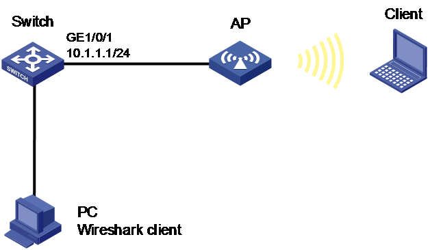
Network configuration
As shown in Figure 2, enable remote packet capture on GigabitEthernet 1/0/1 of the AP and use Wireshark to display the captured packets.

Procedure
1. Configure the AP:
# Configure remote packet capture on GigabitEthernet 1/0/1 of the AP. Set the RPCAP service port number to 2014.
<AC> packet-capture remote ap ap1 gigabitethernet 1/0/1 port 2014
2. Configure Wireshark:
a. Start Wireshark on the PC and select Capture > Options.
b. Select Remote from the Interface list.
c. Enter the IP address of the AP 10.1.1.1 and the RPCAP service port number 2014. Make sure there are routes available between the IP address and the PC.
d. Click OK and then click Start to start packet capture.
The captured packets are displayed on the Wireshark.
