- Released At: 08-05-2025
- Page Views:
- Downloads:
- Table of Contents
- Related Documents
-
|
|
|
|
|
TWAMP Light Technology White Paper |
|
|
Copyright © 2021 New H3C Technologies Co., Ltd. All rights reserved.
No part of this manual may be reproduced or transmitted in any form or by any means without prior written consent of New H3C Technologies Co., Ltd.
Except for the trademarks of New H3C Technologies Co., Ltd., any trademarks that may be mentioned in this document are the property of their respective owners.
This document provides generic technical information, some of which might not be applicable to your products.
The information in this document is subject to change without notice.
Contents
Packet loss measurement mechanism
Measurement mechanism of two-way delay and jitter
IP network performance measurement
VPN network performance measurement
Overview
Two-Way Active Measurement Protocol (TWAMP) defines a standard to measure the round-trip network performance between network devices on an IP network. It uses test packets to measure the two-way delay, jitter, and packet loss. TWAMP Light is a light version of TWAMP. It simplifies the control protocol for establishing performance measurement sessions and improves test performance, thus gaining increasing popularity among customers.
Technical background
With the rapid development of network technologies, delay- and packet loss-sensitive services such as audio, video, and game services impose higher requirements on network performance. The network administrator needs a measurement tool to understand the network performance so they can make adjustments in time to guarantee delivery of such services.
Benefits
Common network performance measurement methods include NQA and RFC 6374/6375 (for MPLS networks). Compared with these measurement methods, TWAMP Light provides the following benefits:
· Defined by the IP Performance Measurement (IPPM) working group, TWAMP Light has a unified measurement model and unified packet format for interoperability among devices of different vendors.
· TWAMP Light can be deployed in IP, MPLS, and L3VPN networks to meet the measurement requirements of different networks.
· TWAMP Light uses the client-server model and it generates and maintains the performance measurement data only on the TWAMP Light client. The network management device can directly obtain the measurement data from the TWAMP Light client.
· Different from standard TWAMP, TWAMP Light moves part of the server functionality to the client and simplifies the control protocol for establishing performance measurement sessions. This greatly reduces the requirements on the server and facilitates rapid server deployment.
Implementation
Architecture

Figure 1 shows the TWAMP Light roles and the typical network diagram.
The client has the following roles:
· TWAMP Light client—Configures TWAMP Light test sessions.
· TWAMP Light sender—Starts and stops TWAMP Light test sessions. The TWAMP Light sender is the source device of the TWAMP Light test.
The server acts as the destination device of the TWAMP Light test and is configured with the TWAMP Light responder role. The responder reflects test packets back to the TWAMP Light sender.
Packet format
A TWAMP Light test uses test request packets and test response packets.
Test request packet format
Figure 2 Test request packet format
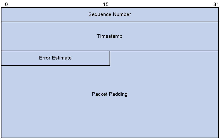
The TWAMP Light sender sends a test request packet to the TWAMP Light responder. A test request packet contains the following fields:
· Sequence Number—Sequence number of the test packet.
· Timestamp—Time when the test packet is sent. Both NTP and PTP timestamp formats are supported and the timestamp format used depends on the value of the Z bit in the Error Estimate field.
· Error Estimate—Estimate of the error in seconds. It has the following format:
¡ S—Uses value 0, indicating that no external clock is used.
¡ Z—Timestamp format. Value 0 indicates the NTP timestamp format and value 1 indicates the PTP timestamp format.
¡ Scale—Uses value 0x3F.
¡ Multiplier—Uses value 0xFF.
Figure 3 Error Estimate field format
![]()
· Packet Padding—Random data for padding.
Test response packet format
Figure 4 Test response packet format
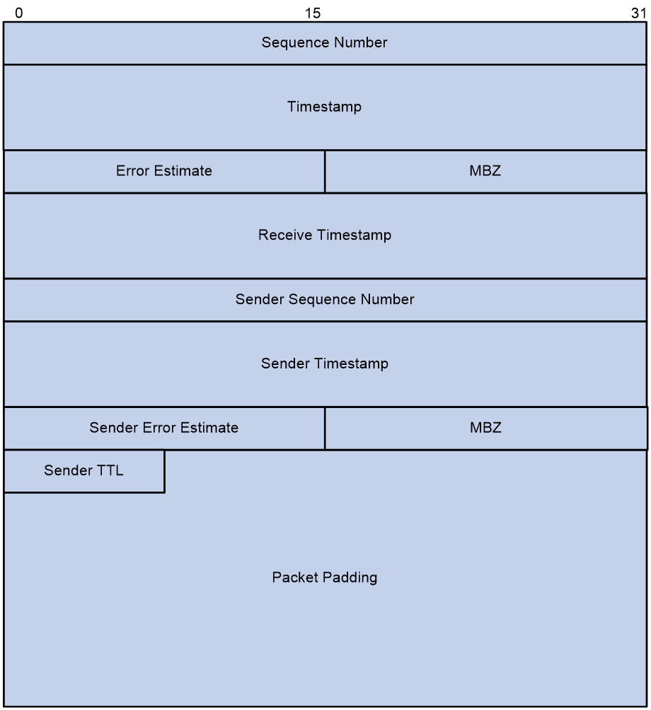
After the TWAMP Light responder receives a test request packet, it sends a test response packet to the TWAMP Light client. A test response packet contains the following fields:
· Sequence Number—Sequence number of the test packet.
· Timestamp—Time when the test packet is sent. Both NTP and PTP timestamp formats are supported and the timestamp format used depends on the value of the Z bit in the Error Estimate field.
· Error Estimate—Estimate of the error in seconds. This field has the same format as described in test request packet.
· MBZ—The value must be zero.
· Receive Timestamp—Time when the test packet is received, in timestamp format. Both NTP and PTP timestamp formats are supported and the timestamp format used depends on the value of the Z bit in the Error Estimate field.
· Sender Sequence Number—Sequence number of the test request packet, copied from the Sequence Number field in the test request packet.
· Sender Timestamp—Timestamp of the test request packet, copied from the Timestamp field in the test request packet.
· Sender Error Estimate—Estimate of error in the test request packet, copied from the Error Estimate field in the test request packet.
· Sender TTL—Time to live in the test request packet, copied from the TTL field in the test request packet.
· Packet Padding—Random data for padding.
Mechanism
Operating mechanism
Figure 5 Operating mechanism of the TWAMP Light test
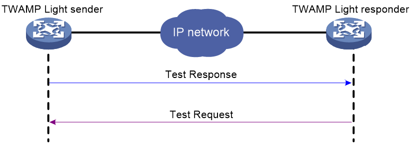
As shown in Figure 5, a TWAMP Light test works as follows:
1. The TWAMP Light sender uses the pre-set IP address, UDP port number and other parameters to construct a test request packet and send the packet to the TWAMP Light responder.
After a TWAMP Light test starts, the TWAMP Light client repeats the test at the specified interval. Each test sends one test packet.
2. Based on the received the test request packet, the TWAMP Light responder adds the timestamp and TTL to construct a test response packet and sends the packet to the TWAMP Light sender.
3. The TWAMP Light sender uses the number of received response packets and receiving time of the response packet to calculate the packet loss rate, two-way delay, and two-way jitter. Thus, the network administrator can determine the quality of the link from source to destination and from destination to source.
Packet loss measurement mechanism
As shown in Figure 6, TWAMP Light uses the following packet loss measurement process:
1. t0—The sender starts the first sent packet statistical period, the first received packet statistical period, and the packet counters. During the sent packet statistical period, the sender periodically sends test request packets to the responder at the specified packet sending interval.
2. t1—The sender receives the first test response packet from the responder.
3. t2—At the end of the first sent packet statistical period, the sender counts the number of sent test request packets. It also starts the second sent packet statistical period, the second received packet statistical period, and the packet counters.
4. t3—At the end of the first received packet statistical period, the sender counts the number of received test response packets, and calculates the packet loss rate in the first sent packet statistical period.
Packet loss rate = (Number of sent packets in period n – number of received packets in period n) / Number of the sent packets in period n
5. t4—At the end of the second sent packet statistical period, the sender counts the number of sent test request packets. It also starts the next sent packet statistical period, the next received packet statistical period, and the packet counters.
6. t5—At the end of the second received packet statistical period, the sender counts the number of received test response packets, and calculates the packet loss rate in the second sent packet statistical period.
7. The sender repeats the preceding process until the TWAMP Light test stops.
Figure 6 Packet loss measurement mechanism
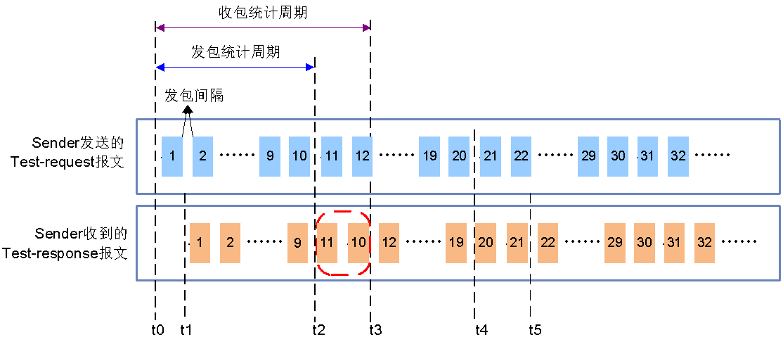
To ensure the accuracy of the measurement result, TWAMP Light uses the following methods:
· Set the received packet statistical period longer than the sent packet statistical period. This helps prevents late arriving response packets (caused by network transmission delay or out-of-order transmission) from being excluded from statistics collection.
As shown in Figure 6, the sender counts response packet 10 in the first received packet statistical period although the packet is received after the first sent packet statistical period has ended.
· Use the sequence number to identify the sent packet statistical period of a test response packet.
a. The sender automatically assigns a sequence number to each test request packet.
b. The responder copies the sequence number of the received test request packet to the Sender Sequence Number field of the test response packet.
c. The sender identifies the statistical period of the received test response packet according to the Sender Sequence Number field.
As shown in Figure 6, the sender counts only packets 1 to 10 in the first sent packet statistical period and packets 11 to 20 in the second sent packet statistical period.
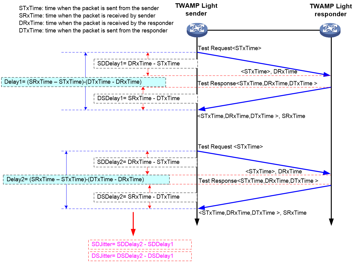
Measurement mechanism of two-way delay and jitter
As shown in Figure 7, the TWAMP Light sender sends the timestamped packets periodically to calculate the two-way delay and packet jitter as follows:
1. The sender sends a test request packet containing the STxTime timestamp to the responder.
2. The test request packet arrives at the responder and the responder records the DRxTime timestamp.
3. According to the received test request packet, the responder constructs a test response packet containing the STxTime, DRxTime, and estimated DTxTime timestamps and sends the packet to the sender.
4. Upon receiving the test response packet, the sender records the SRxTime timestamp and calculates the two-way delay (Delay1) based on the STxTime, DRxTime, DTxTime, and SRxTime timestamps for the packet.
5. The sender repeats the preceding process to calculate the two-way delay for subsequent test packets, the source-to-destination jitter, and the destination-to-source -jitter.
Figure 7 Measurement mechanism of two-way delay and jitter
Application scenarios
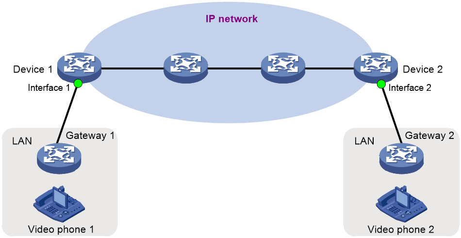
IP network performance measurement
As shown in Figure 8, the audio and video streams stutter during a video conference between video phone 1 and video phone 2. Use TWAMP Light to measure the network performance to confirm whether severe packet loss, packet delay, or packet jitter occurs when the audio and video traffic travels across the IP network.
Configure TWAMP Light on Device 1 and Device 2 to measure the two-way delay, jitter, and packet loss rate between the devices.
VPN network performance measurement
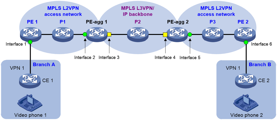
As shown in Figure 9, the two branches of a company (Branch A and Branch B) communicate with each other over the VPN network. The audio and video streams stutter during a video conference between Branch A and Branch B. Use TWAMP Light to measure the network performance to confirm whether and where severe packet loss, packet delay, and packet jitter occur when the audio and video traffic travels across the VPN network.
Configure TWAMP Light on PE 1 and PE 2 to measure the carrier network performance from interface 1 to interface 6. If severe packet loss or packet delay occurs, continue with the following steps to locate the network faults:
1. Configure TWAMP Light on PE 1 and PE-agg 1 to measure the MPLS L2VPN network performance from interface 1 to interface 2.
2. Configure TWAMP Light on PE-agg 1 and PE-agg 2 to measure the MPLS L3VPN network performance from interface 3 to interface 4.
3. Configure TWAMP Light on PE 1 and PE-agg 2 to measure the network performance from interface 1 to interface 5 when the traffic sends from an MPLS L2VPN to the other MPLS L2VPN across the MPLS L3VPN/IP backbone.