- Released At: 12-05-2025
- Page Views:
- Downloads:
- Table of Contents
- Related Documents
-
Copyright © 2021 New H3C Technologies Co., Ltd. All rights reserved. No part of this manual may be reproduced or transmitted in any form or by any means without prior written consent of New H3C Technologies Co., Ltd. Except for the trademarks of New H3C Technologies Co., Ltd., any trademarks that may be mentioned in this document are the property of their respective owners. This document provides generic technical information, some of which might not be applicable to your products. The information in this document is subject to change without notice. |
Contents
Typical collaboration between Smart Link and Monitor Link
Cascaded deployment of Smart Link and Monitor Link
Collaboration between Smart Link and RRPP
Smart Link overview
Technical background
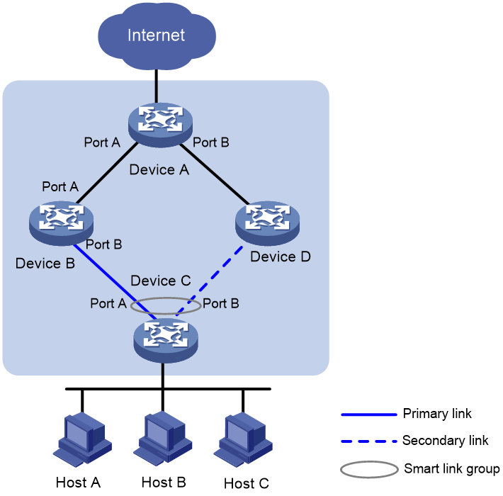
Smart Link provides link redundancy and subsecond convergence time in a dual uplink network. As shown in Figure 1, Smart Link is configured on Device C and Device D. The secondary link takes over quickly when the primary link fails.
Benefits
Smart Link is dedicated to dual-uplink networks. It delivers the following benefits:
· Keeping one uplink connected and the other blocked when both uplinks in a dual uplink network are healthy, thus preventing broadcast storms caused by network loops.
· Switching the traffic to the secondary link within a few subseconds when the primary link fails, thus ensuring the normal forwarding of traffic in the network.
Smart Link implementation
Concepts
Smart link group
A smart link group consists of two member ports: the primary port and the secondary port. A port can belong to different smart link groups at the same time. Normally, at a time, only one port (master or secondary) is active for forwarding, while the other port is blocked, that is, in the standby state. When link failure occurs on the active port due to port shutdown or Ethernet OAM link errors for example, the standby port becomes active to take over while the former active port transits to the blocked state.
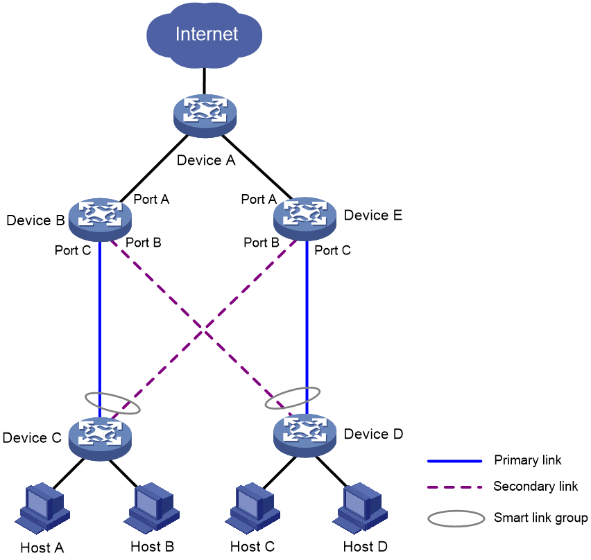
Figure 2 Smart Link application scenario
As shown in Figure 2, Port A and Port B of Device C form a smart link group. Port A is in the forwarding state, and Port B is in the blocked state. Port A and Port B of Device D form another smart link group. Port B is in the blocked state, and Port A is in the forwarding state.
Primary port
The primary port of a smart link group is a port role specified using commands. It can be an Ethernet port (electrical or optical), or an aggregate interface.
As shown in Figure 2, the active port in the smart link group configured on Device C is the primary port Port A.
Secondary port
The secondary port of a smart link group is another port role specified using commands. It can be an Ethernet port (electrical or optical), or an aggregate interface. The link on which the secondary port resides is called the secondary link.
As shown in Figure 2, the blocked port in the smart link group on Device C is the secondary port Port B.
Protected VLAN
A protected VLAN is a VLAN that carries user data traffic within a smart link group. A port can belong to multiple smart link groups, each having a different protected VLAN. Each smart link group independently calculates the state of its own member ports.
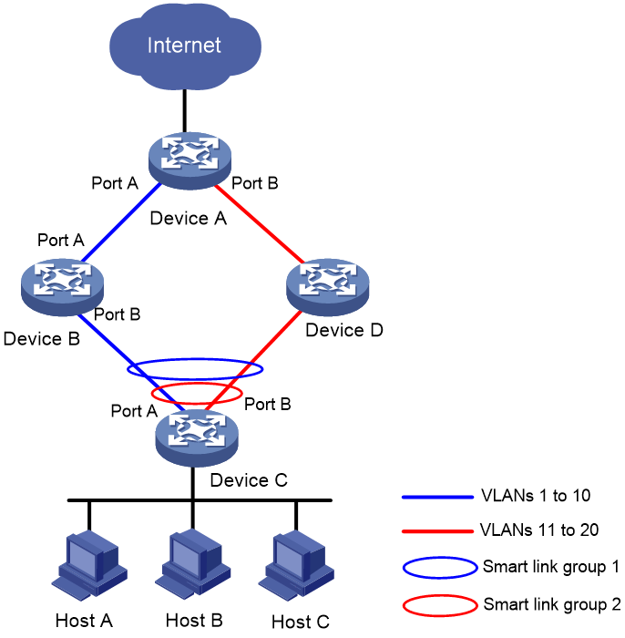
As shown in Figure 3, smart link group 1 and smart link group 2 are created on Device C. smart link group 1 protects VLANs 1 to 10, while smart link group 2 protects VLANs 11 to 20. In this way, the traffic of the two VLAN groups can be forwarded through different ports.
Flush message
When link switchover occurs in a smart link group, the old forwarding entries are no longer useful for the new topology. Therefore, all devices in the network need to refresh their MAC address entries and ARP entries. Smart Link notifies devices to refresh their MAC address entries and ARP entries by sending flush messages to them.
A flush message uses the IEEE802.3 encapsulation format. It contains fields such as Destination MAC Address, Source MAC Address, Control VLAN ID, and VLAN Bitmap. Figure 4 shows the format of a flush message.
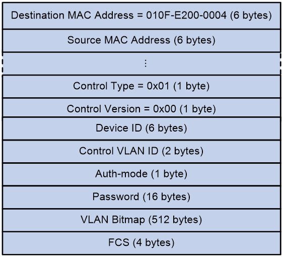
· The Destination MAC Address field indicates an unknown multicast address. 0x010F-E200-0004 is the destination MAC address of a flush message.
· The Source MAC Address field indicates the interface MAC address of the device that sends the flush message. If the interface does not have a MAC address, the default MAC address of the Layer 2 protocol is used.
· Currently, only one control type, 0x01, is available, which is used to delete MAC address entries and ARP entries.
· The current control version is 0x00, which is used for the expansion of later versions.
· Device ID indicates the bridge MAC address of the device that sends the flush message.
· Control VLAN ID indicates the ID of the transmit control VLAN.
· Auth-mode indicates the authentication mode. It is used in conjunction with the Password field for subsequent security expansion.
· VLAN bitmap is used to carry a list of VLANs whose MAC address table entries need to be refreshed.
· FCS indicates the frame check sequence, which is used to check bit errors in frames.
Control VLAN
Transmit control VLAN
A transmit control VLAN is a VLAN used by a smart link group to broadcast flush messages.
When a link switchover occurs, the devices broadcast flush messages in the transmit control VLANs using the new forwarding links.
Receive control VLAN
A receive control VLAN is a VLAN used by an upstream device to receive and process flush messages.
When a link switchover occurs, the upstream devices process flush messages from the receive control VLANs, and refresh their MAC address entries and ARP entries.
Mechanism
Link backup
When both uplinks are healthy, the primary port is in the forwarding state, while the secondary port is in the standby state, and the links on which the two ports are seated respectively are called the primary link and the secondary link. In this case, data is transmitted along the primary link. No loop exists in the network, and no broadcast storms will occur.
Link switchover
When the primary link fails, the primary port transits to the standby state, while the secondary port transits to the forwarding state. A link switchover occurs. After the link switchover, the MAC address entries and ARP entries kept on the devices in the network might become incorrect, and need to be refreshed, so that traffic can be rapidly switched to another link, thus avoiding traffic loss. Currently, two mechanisms are available for refreshing MAC address entries and ARP entries.
Flush message-notified refreshing
This mechanism is applicable when the upstream devices (Device A, Device B, and Device D in Figure 5) support Smart Link and are able to recognize flush messages.
To enable rapid link switchover, you need to enable Device C to send flush messages, and all upstream devices’ ports that are on the dual uplink network to receive and process flush messages.
1. After link switchover occurs on Device C, flush messages are sent along the new forwarding link, that is, through Port B. The VLAN Bitmap field is filled by the protected VLAN IDs of the smart link group where Port A is in the forwarding state before the link switchover, and the Control VLAN ID field is filled by the transmit control VLAN ID of the smart link group.
2. When an upstream device receives a flush message, it determines whether the transmit VLAN ID carried in the flush message is among the receive control VLAN list configured on the receiving port. If not, the upstream device simply forwards the flush message. If yes, the device retrieves the VLAN Bitmap information from the flush message, and deletes the MAC address entries and ARP entries learned in the VLANs specified in the VLAN Bitmap field.
After that, when Device A receives a data packet destined for Device C: if Layer 2 forwarding is required, it broadcasts the packet at Layer 2; if Layer 3 forwarding is required, it updates the ARP entries using the ARP probing mechanism, and then forwards the packet. In this way, data traffic can be forwarded correctly.
With this mechanism, the upstream devices refresh their MAC address entries and ARP entries based on received flush messages, instead of waiting until these entries age out. In this way, the time required for refreshing MAC address entries and ARP entries is considerably reduced. Typically, a link switchover is completed within a few subseconds with no traffic loss.
|
|
NOTE: · To ensure that flush messages can be correctly transmitted within the transmit control VLAN, make sure that all ports on the dual uplink network belong to the transmit control VLAN. Otherwise, flush messages cannot be successfully transmitted or forwarded. · As a best practice, send flush messages tagged. To send flush messages untagged, make sure that the default VLAN of the peer port is the same as the transmit control VLAN. Otherwise, flush messages will not be transmitted within the transmit control VLAN. |
Uplink traffic-triggered refreshing
This mechanism is applicable when devices that do not support Smart Link or other vendors’ devices are connected. In such cases, the refreshing of the MAC address entries and ARP entries is triggered by uplink traffic.
· If no uplink traffic from Device C arrives at Device A to trigger the refreshing of the MAC address entries and ARP entries, when Device A receives a data packet destined for Device C, it still forwards the packet out Port A, and thus fails to send the packet to Device C. The MAC address entries and ARP entries will not be refreshed until their aging timers expire.
· Because the MAC address entries and ARP entries on Device C are also incorrect, Device C cannot send uplink traffic until its MAC address entries and ARP entries age out and new MAC address entries and ARP entries are learned. When uplink traffic from Device C arrives at Device A through Port B, Device A refreshes its own MAC address entries and ARP entries. After that, when Device A receives a data packet destined for Device C, it forwards the packet out Port B. This time the packet can reach Device C through Device D.
Link recovery
Smart Link supports role preemption, speed preemption, and no preemption. The link recovery processes differ by preemption mode as follows:
· If role preemption is configured, when the primary link recovers, the primary port enters the forwarding state and takes over the traffic, while the secondary port enters the standby state. The secondary port transits from standby to forwarding only when the primary link fails.
· If speed preemption is configured, the following conditions occur when the primary link recovers:
¡ If you specify the threshold threshold-value option, the primary port transitions to forwarding state when the difference between the primary port speed and the secondary port speed equals or exceeds the threshold value (in percentage) of the secondary port speed.
¡ If you do not specify the threshold threshold-value option, the primary port transitions to forwarding state when the primary port speed exceeds the secondary port speed.
· If no preemption is configured, when the primary link recovers, the secondary port remains in the forwarding state, while the primary port remains in the standby state, so as to keep the traffic stable.
As shown in Figure 6, when the link of Port A on Device C recovers:
· If role preemption is configured on the smart link group on Device C, Port B is immediately blocked and transits to the standby state, while Port A transits to the forwarding state.
· If no preemption is configured, Port A remains in the standby state, and no link switchover occurs, thus keeping the traffic stable.
Figure 6 Smart Link link recovery mechanism

Load sharing
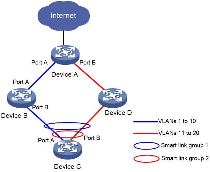
Data traffic of multiple VLANs may exist in a dual uplink network. By configuring Smart Link, you can achieve load sharing in the network, that is, transmit traffic of different VLANs along different paths. By configuring the two ports on the dual uplinks as members of two smart link groups (each having its own protected VLANs), each port having the opposite roles in different smart link groups, you can enable protected VLAN traffic of different smart link groups to be transmitted along different paths, thus achieving load sharing in the network.
As shown in Figure 7, two smart link groups are created on Device C and have different protected VLANs. Both of them are configured with the role preemption mode. smart link group 1’s primary port is Port A, secondary port is Port B, and protected VLANs are VLAN 1 through VLAN 10; smart link group 2’s primary port is Port B, secondary port is Port A, and protected VLANs are VLAN 11 through VLAN 20. Both smart link groups’ primary ports are in the forwarding state. Thus configured, traffic of VLAN 1 through VLAN 10 is transmitted along the link indicated by the blue line, and that of VLAN 11 through VLAN 20 is transmitted along the link indicated by the red line. In this way, VLAN traffic is shared on the two uplinks.
Figure 7 Smart Link load balancing
As a best practice, configure role preemption or speed preemption for the smart link groups. If no preemption mode is configured, all traffic will be transmitted along one path upon a link switchover, and will remain that way even after the failed uplink recovers. Load sharing will no longer be performed.
Restrictions
· You cannot assign an STP- or RRPP-enabled port to a smart link group as a member port.
· You cannot assign a member port of an aggregation group or service loopback group to a smart link group as a member port.
Monitor Link overview
Technical background
Monitor Link associates the state of downlink interfaces with the state of uplink interfaces in a monitor link group. When Monitor Link shuts down the downlink interfaces because of an uplink failure, the downstream device changes connectivity to another link.
As shown in Figure 8, a smart link group is configured on Device C for link redundancy purposes, with Port A as the primary port, and Port B as the secondary port. The links attached to Port A and Port B are the primary link and secondary link, respectively. When the primary link fails, traffic switches to the secondary link within a few subseconds. Smart Link delivers reliable link redundancy and rapid convergence.
Traffic will be interrupted if the uplink of Device B fails and no link switchover happens in the smart link group (because the primary link is still healthy). Traffic sent out of Port A of Device C can no longer reach Device A. To address this problem, the Monitor Link technology is introduced.
Figure 8 Monitor Link background

Benefits
Monitor Link is developed to complement the Smart Link feature. By monitoring the uplink, and synchronizing the downlink with the uplink, Monitor Link triggers the switchover between the primary and secondary links in a smart link group, thus perfecting the link redundancy mechanism of Smart Link.
Monitor Link implementation
Concepts
Monitor link group
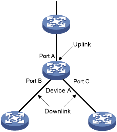
A monitor link group is a set of uplink and downlink interfaces. Downlink interfaces adapt to the state changes of uplink interfaces. As shown in Figure 9, Port A, Port B, and Port C of Device A form a monitor link group.
Figure 9 Monitor Link basic concepts
Uplink interface
An uplink interface is a monitored port in a monitor link group. It is a port role specified using commands. It can be an Ethernet port (electrical or optical), or an aggregate interface.
As shown in Figure 9, Port A of Device A is the only uplink interface of the monitor link group configured on the device.
When the number of uplink interfaces in up state in a monitor link group is less than the specified threshold, the monitor link group goes down and shuts down its downlink interfaces. When the number of uplink interfaces in up state reaches the threshold, the monitor link group comes up and brings up all its downlink interfaces. If no uplink interface is specified in a monitor link group, the system considers the monitor link group’s uplink interfaces to be faulty, and thus shuts down all the downlink interfaces in the monitor link group.
Downlink interface
A downlink interface is a monitoring port in a monitor link group. It is another port role specified using commands. It can be an Ethernet port (electrical or optical), or an aggregate interface.
As shown in Figure 9, Port B and Port C of Device A are two downlink interfaces of the monitor link group configured on the device.
|
|
NOTE: When a monitor link group’s uplink interfaces recover, only downlink interfaces that were blocked due to uplink interface failure will be brought up. Downlink interfaces manually shut down will not be brought up automatically. The failure of a downlink interface does not affect the uplink interfaces or other downlink interfaces. |
Mechanism
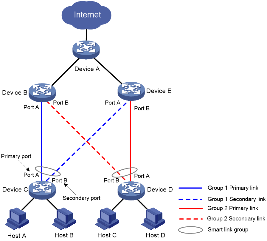
As shown in Figure 10, to provide reliable access to the Internet for the hosts, a smart link group is configured on Device C. Port A is the primary port of the smart link group, and is in the forwarding state. Port B is the secondary port.
To avoid traffic interruption due to the failure of the uplink of Device B, configure a monitor link group on Device B. Specify Port A as the uplink interface and Port B as the downlink interface for the monitor link group.
Figure 10 Monitor Link mechanism

When the uplink of Device B fails, the monitor link group shuts down downlink interface Port B, triggering a link switchover in the smart link group configured on Device C.
When the uplink of Device B recovers, the monitor link group brings up downlink interface Port B. This triggers another link switchover in the smart link group if role preemption is configured in the smart link group on Device C.
Monitor Link and Smart Link cooperate to deliver reliable link redundancy and fast convergence for dual-uplink networks.
Restrictions
You cannot assign a member port of an aggregation group or service loopback group to a monitor link group as a member port.
Application scenarios
Typical collaboration between Smart Link and Monitor Link
Figure 11 shows a typical dual uplink network, which is a major application scenario for Smart Link and Monitor Link.
Figure 11 Collaboration between Smart Link and Monitor Link
In the above application environment, Smart Link is configured on Device C and Device D. By configuring multiple smart link groups on the devices and assigning different protected VLANs to them, you can transmit traffic of protected VLANs that belong to different smart link groups along different paths, thus achieving load sharing. When the link between Device B and Device C, or that between Device D and Device E fails, the smart link groups can immediately sense the link failure and switch over links.
To enable Device C (or Device D) to directly sense the failure of the link between Device A and Device B (or Device E), you need to configure a monitor link group on Device B (or Device E), with Port A as the uplink interface, and Port B and Port C as the downlink interfaces.
Cascaded deployment of Smart Link and Monitor Link
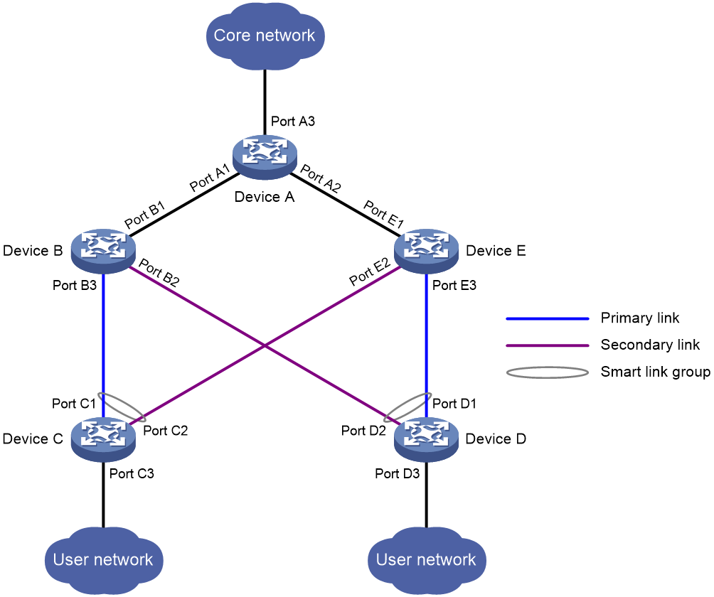
Figure 12 shows an application scenario where Smart Link is cascaded with Monitor Link to achieve more reliable link redundancy.
A smart link group member port can be assigned to a monitor link group as its uplink interface. By using the Smart Link and Monitor Link technologies together, you can cascade the secondary links.
To do that, you need to configure the two member ports of a smart link group as the uplink interfaces of a monitor link group, with the peer of the monitor link group’s downlink interface as the master or secondary port of another smart link group, as shown in Figure 12.
Figure 12 Cascaded smart link groups
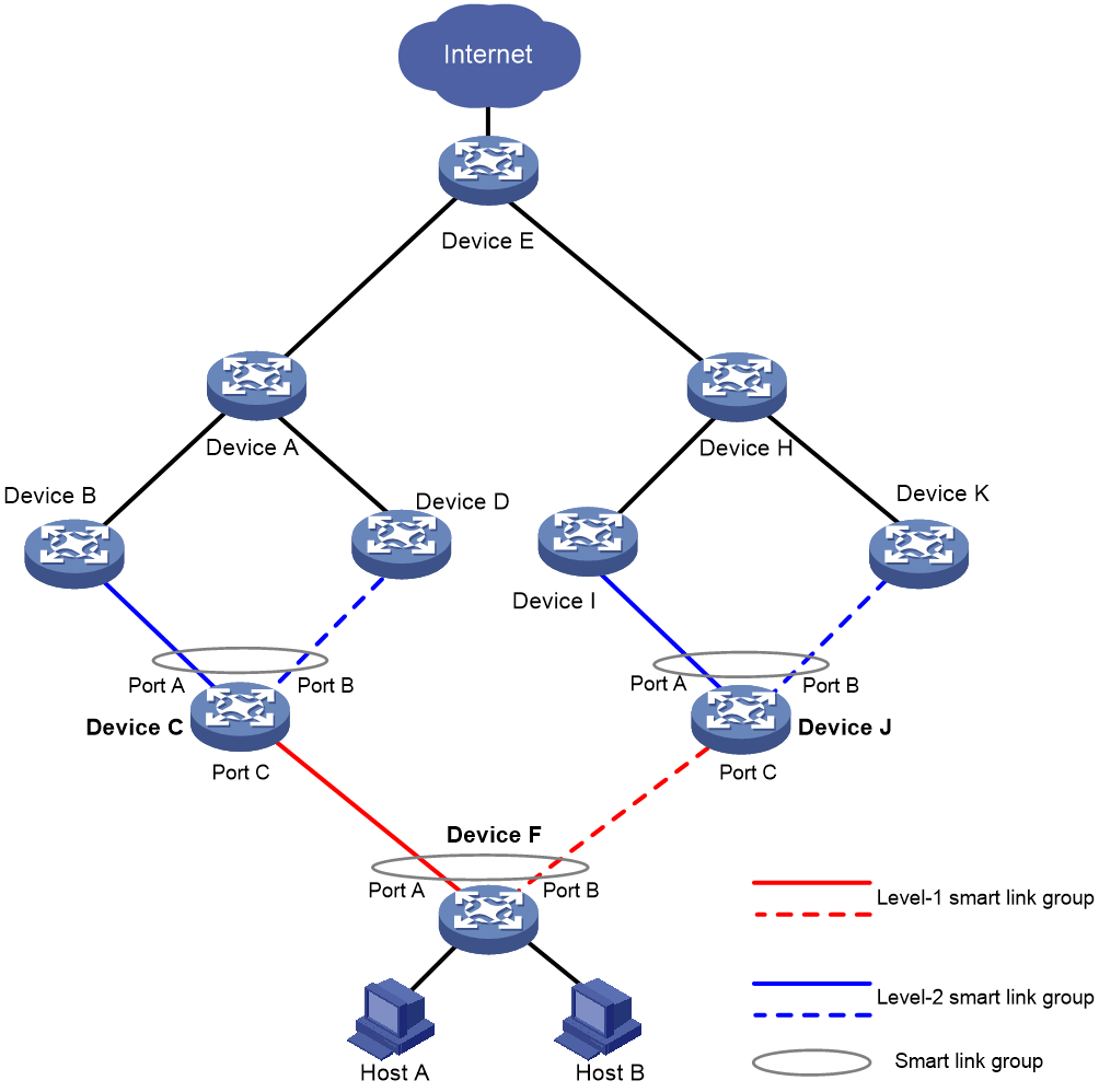
Table 1 lists the roles of ports on Device C, Device J, and Device F in Smart Link and Monitor Link shown in Figure 12.
Table 1 Smart Link and Monitor Link port roles
|
Device |
Smart link group 1 |
Monitor link group 1 |
||
|
Primary port |
Secondary port |
Uplink interface |
Downlink interface |
|
|
Device C |
Port A |
Port B |
Port A and Port B |
Port C |
|
Device J |
Port A |
Port B |
Port A and Port B |
Port C |
|
Device F |
Port A |
Port B |
No monitor link group is configured. |
|
Collaboration between Smart Link and RRPP
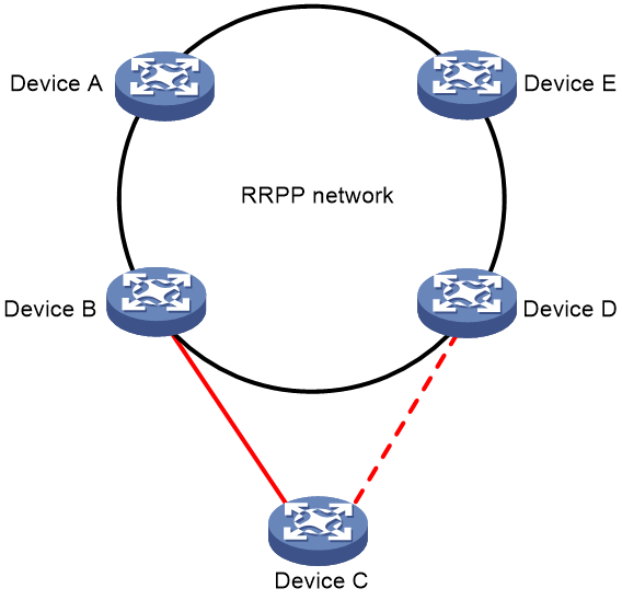
Figure 13 shows a hybrid network of Smart Link and RRPP.
In this network, RRPP is enabled on Device A, Device B, Device D, and Device E to provide link redundancy. A smart link group is configured on Device C.
If STP is used to provide link redundancy, you need to enable STP on all ports connecting Device B, Device D, and Device C. Because RRPP, which is mutually exclusive with STP, is enabled on the two ports connecting Device B and Device D, you can achieve link redundancy for Device C by configuring a smart link group on Device C, which is not only simpler than configuring RRPP subrings on Device B, Device C, and Device D, but also applies to the scenario where Device C does not support RRPP.
Figure 13 Smart Link-RRPP hybrid network