- Released At: 08-05-2025
- Page Views:
- Downloads:
- Table of Contents
- Related Documents
-
|
|
|
PPPoE Technology White Paper |
|
|
|
|
|
|
Copyright © 2021 New H3C Technologies Co., Ltd. All rights reserved.
No part of this manual may be reproduced or transmitted in any form or by any means without prior written consent of New H3C Technologies Co., Ltd.
Except for the trademarks of New H3C Technologies Co., Ltd., any trademarks that may be mentioned in this document are the property of their respective owners.
The information in this document is subject to change without notice.
Contents
Benefits for service providers
Router-initiated network structure
Host-initiated network structure
Connecting a LAN to the Internet using an ADSL modem
Overview
Technical background
Now, the service providers pose much higher requirements on the broadband access technologies. Traditional broadband access technologies (for example, xDSL, CableModem, and Ethernet) gradually cannot meet such requirements in user management and accounting.
Among numerous access technologies, Ethernet access is economical, and PPP can provide good access control and accounting functions. Combining the economy of Ethernet and the good scalability and management & control functions of PPP, Point-to-Point Protocol over Ethernet (PPPoE) was introduced.
Because PPPoE well solves the practical application problems such as user management and network access accounting, PPPoE is widely recognized and used by service providers.
Benefits
Benefits for end users
For end users, PPPoE delivers the following benefits:
· Adopting the traditional dial-up access mode, which allows end users to use the familiar hardware and similar software to access the Internet.
· Compatible with all the existing xDSL modems. No complicated configurations are required on the clients’ xDSL modems.
· Using Ethernet adapters to connect PCs and xDSL modems, which allows PCs to share xDSL lines and thus saves investment.
Benefits for service providers
For service providers, PPPoE delivers the following benefits:
· Allowing service providers to provide broadband access services for a large number of end users through digital subscriber lines, cable modems, or wireless access devices.
· Allowing service providers to quickly deploy high-speed Internet services by using reliable, mature technologies, thus minimizing impact on the current networks.
· Allowing service providers to authenticate end users with the access control function, perform accounting with the accounting function, and monitor user behavior so as to ensure network security.
· Allowing end users to access network services provided by different service providers at the same time. This dynamic subscription mode enables the service providers to easily develop and provide new services.
PPPoE implementation
PPPoE network structures
PPPoE uses the client/server model. The PPPoE client initiates a connection request to the PPPoE server. After session negotiation between them is complete, a session is established between them, and the PPPoE server provides access control, authentication, and accounting to the PPPoE client.
PPPoE network structures are classified into router-initiated and host-initiated network structures depending on the starting point of the PPPoE session.
Router-initiated network structure
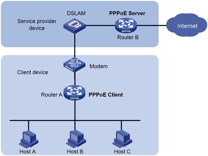
As shown in Figure 1, the PPPoE session is established between routers (Router A and Router B). All hosts share one PPPoE session for data transmission without being installed with PPPoE client dialup software. This network structure is typically used by enterprises. An enterprise can one account to access the Internet.
Figure 1 Router-initiated network structure
Host-initiated network structure
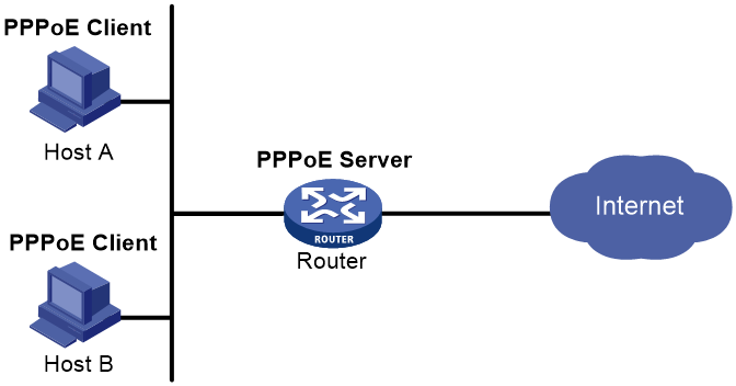
As shown in Figure 2, a PPPoE session is established between each host (PPPoE client) and the service provider router (PPPoE server). The service provider assigns an account to each host for accounting and control. Each host must be installed with PPPoE client dialup software.
Figure 2 Host-initiated network structure
PPPoE packets
PPPoE packet format
A PPPoE packet is a PPP packet encapsulated in an Ethernet frame, as shown in Figure 3.
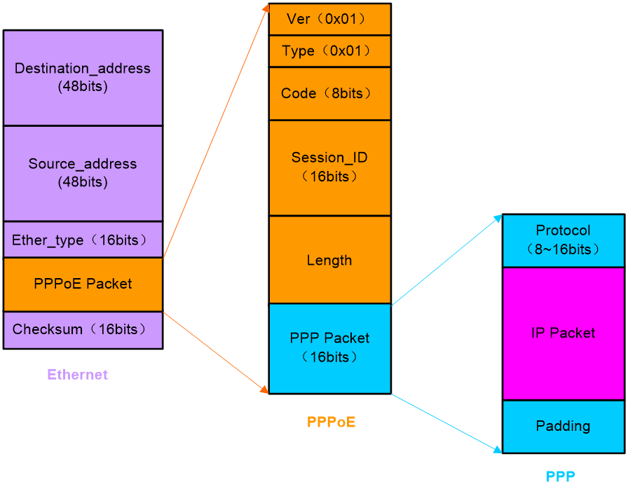
The field descriptions are as follows:
· Destination_address—A unicast Ethernet destination address or Ethernet broadcast address (0xffffffff). In a discovery packet, this field is a unicast or broadcast address. The PPPoE client uses a broadcast address to discover the PPPoE server. After the PPPoE server is determined, unicast addresses are used for communication. During the Session stage, this field must be the unicast address of the peer determined during the Discovery stage.
· Source_address—Ethernet MAC address of the source device.
· Ether_type—The value is 0x8863 during the Discovery or Terminate stage or 0x8864 during the Session stage.
· Ver—PPPoE version number, 4 bits in length, with the value 0x1.
· Type—PPPoE type, 4 bits in length, with the value 0x1.
· Code—PPPoE packet type, 8 bits in length. Possible code values are as follows:
¡ 0x00—Session data.
¡ 0x09—PPPoE Active Discovery Initiation (PADI) packets.
¡ 0x07—PPPoE Active Discovery Offer (PADO) or PPPoE Active Discovery Terminate (PADT) packets.
¡ 0x19—PPPoE Active Discovery Request (PADR) packets.
¡ 0x65—PPPoE Active Discovery Session-confirmation (PADS) packets.
· Session_ID—Unique identifier of a PPP session, 16 bits in length. It is fixed for a given PPP session and in fact, defines a PPP session together with the Source_address and Destination_address fields. The value 0xffff is reserved for future use and must not be used.
· Length—The Length field is 16 bits long and represents the length of the PPPoE Payload. It does not indicate the length of the Ethernet or PPPoE headers.
PADI packets
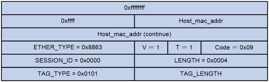
As shown in Figure 4, the major fields in a PADI packet are as follows:
· The Code value is 0x09.
· The SESSION_ID value is 0x0000.
· The TAG_TYPE value is 0x0101 (Service-Name), indicating that a service name follows. There is only one tag with the TAG_TYPE value being Service-Name. The other tags are optional.
Figure 4 PADI packet structure
PADO packets
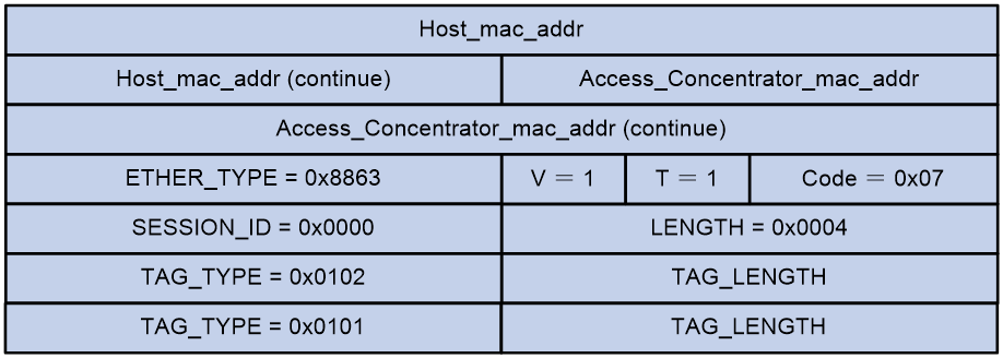
As shown in Figure 5, the major fields in a PADO packet are as follows:
· The Code value is 0x07.
· The SESSION_ID value is 0x0000.
· The TAG_TYPE value being 0x0101 (Service-Name) indicates that a service name follows; being 0x0102 (AC-Name) indicates that the following string uniquely identifies a particular access concentrator. There is only one tag with the TAG_TYPE value being AC-Name, and at least one tag with the TAG_TYPE value being Service-Name.
Figure 5 PADO packet structure
PADR packets
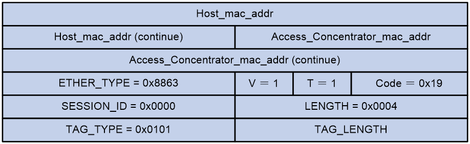
As shown in Figure 6, the major fields in a PADR packet are as follows:
· The Code value is 0x19.
· The SESSION_ID value is 0x0000.
· The TAG_TYPE value is 0x0101 (Service-Name), indicating that a service name follows. There is only one tag with the TAG_TYPE value being Service-Name. The other tags are optional.
Figure 6 PADR packet structure
PADS packets
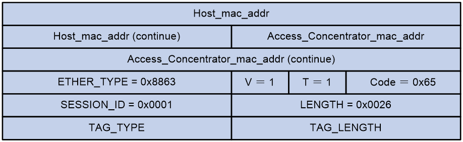
As shown in Figure 7, the major fields in a PADS packet are as follows:
· The Code value is 0x65.
· The SESSION_ID value is the one determined during the Discovery stage.
· The TAG field is optional.
Figure 7 PADS packet structure
PADT packets
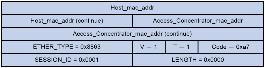
As shown in Figure 8, the major fields in a PADT packet are as follows:
· The Code value is 0xa7.
· The SESSION_ID value is the one determined during the Discovery stage.
· The TAG field is not available.
Figure 8 PADT packet structure
How PPPoE works
Figure 9 shows the PPPoE negotiation process.
Figure 9 PPPoE negotiation process

PPPoE undergoes three stages, including Discovery, Session, and Terminate.
Discovery stage
When the discovery stage is over, both peers know the PPPoE session ID and the MAC address of the peer, which together determine a unique PPPoE session.
The Discovery stage includes the following four steps.
1. The PPPoE client broadcasts a PADI packet that contains information about the service type it requests.
2. After receiving a PADI packet that it can serve, a PPPoE server replies with a PADO packet. The destination address of the PADO packet is the unicast packet of the host that sent the PADI.
3. Depending on the network topology, since the PADI was broadcast, the PPPoE client may receive PADO packets sent by multiple PPPoE servers. Among these PPPoE servers, the PPPoE client selects the one whose PADO packet arrived the earliest and unicasts a PADR packet to the PPPoE server.
4. The PPPoE server generates a unique session ID for the session and sends the session ID to the PPPoE client through a PADS packet. The session will thus be established and PPPoE moves on to the Session stage.
Session stage
The PPP negotiation for a PPPoE session can be further divided into the following three stages, including LCP, authentication, and NCP:
1. LCP is a stage where parameters used to establish, configure, and test the data-link connection are negotiated.
2. After the LCP negotiation succeeds, the authentication is performed with the authentication protocol (CHAP or PAP) agreed upon in LCP negotiation.
3. After the authentication succeeds, PPP enters the NCP stage where different network layer protocols are configured. The PPPoE server and client typically use the IP Control Protocol (IPCP) to configure IP addresses and DNS server information for end users.
After PPP negotiation succeeds, the PPPoE session can carry PPP data packets.
In the Session stage, all Ethernet data packets are sent in unicast mode.
Terminate stage
Application scenarios
Connecting a LAN to the Internet using an ADSL modem
As shown in Figure 10, the enterprise wishes that all its employees access the Internet using a common account:
· Router A serves as the PPPoE client and accesses the Internet with an account, which is the common account used by all the employees to access the Internet.
· Router B serves as the PPPoE server. It connects to a DSLAM on one end, providing functions such as RADIUS authentication and accounting, and to the Internet on the other end.

Wireless PPPoE access
As shown in Figure 11, the APs serve as PPPoE clients and the broadband remote access server (BRAS) serves as the PPPoE server. End users access the Internet through wireless networks.

References
· RFC1661: The Point-to-Point Protocol (PPP)
· RFC2516: A Method for Transmitting PPP Over Ethernet (PPPoE)