- Released At: 08-05-2025
- Page Views:
- Downloads:
- Table of Contents
- Related Documents
-
|
|
|
|
|
MPLS Technology White Paper |
|
|
|
|
Copyright © 2020 New H3C Technologies Co., Ltd. All rights reserved.
No part of this manual may be reproduced or transmitted in any form or by any means without prior written consent of New H3C Technologies Co., Ltd.
Except for the trademarks of New H3C Technologies Co., Ltd., any trademarks that may be mentioned in this document are the property of their respective owners.
This document provides generic technical information, some of which might not be applicable to your products.
The information in this document is subject to change without notice.
Overview
Technical background
The explosive growth of the Internet provides great commercial opportunities for Internet service providers but also raises higher requirements on backbones of the service providers. Users want the IP network to provide not only E-mail and website browsing services but also broadband, real-time services. The Asynchronous Transfer Mode (ATM) technology was once popular for it can provide switching technologies for multiple services. However, ATM is complicated in technology and hard to deploy. Besides, in real networks, the IP technology is widely used and it is impossible to replace all IP networks with ATM networks. Therefore, it is better to have existing IP networks integrated with advantages of ATM networks to provide multiple types of services.
Multiprotocol Label Switching (MPLS) is proposed to satisfy these requirements. It takes the Virtual Path Identifier/Virtual Channel Identifier (VPI/VCI) switching idea of ATM, and seamlessly integrates the flexibility of IP routing and the simplicity of Layer 2 switching. Based on the routing information collected by the Interior Gateway Protocol (IGP) or Border Gateway Protocol (BGP), MPLS establishes virtual connections, that is, label-based forwarding paths, making a connectionless IP network connection-oriented and satisfying the Quality of Service (QoS) requirements of different types of services.
Benefits
MPLS has the following advantages:
· MPLS encapsulates network layer packets with short, fixed-length labels, allowing devices to forward packets based on labels, rather than look up routes according to destination IP addresses at each hop. This improves the forwarding speed dramatically.
· Nodes along packet forwarding paths distribute labels to establish virtual links for packet forwarding, thus providing connection-oriented service for the network layer.
· MPLS supports various link layer protocols and network layer protocols. Working above link layer protocols, such as PPP, ATM, frame relay, and Ethernet, MPLS can provide connection-oriented services for network layer protocols, such as IPv4, IPv6, and IPX.
· MPLS supports not only routing protocols but also policy-based constraint routes, satisfying the networking requirements of various new applications.
· MPLS is widely used. It improves forwarding speed of network devices and has been used widely in large-scaled IP networks for virtual private network (VPN) construction, traffic engineering (TE), and QoS.
MPLS implementation
Concepts
FEC
As a forwarding technology based on classification, MPLS groups packets to be forwarded in the same manner into a class called a forwarding equivalence class (FEC). That is, packets of the same FEC are handled in the same way on an MPLS network.
The classification of FECs is very flexible. It can be based on any combination of source address, destination address, source port, destination port, protocol type and VPN. The device supports classifying FECs only by network layer destination address.
Label
A label is a short, fixed length identifier for uniquely identifying an FEC. A label is locally significant.
A label is four bytes in length. Figure 1 illustrates its format. A label consists of four fields:
· Label—20-bit label value, used for identifying an FEC.
· TC—3-bit traffic class, used for QoS. It is also called Exp.
· S—1-bit bottom of stack flag. A label stack can contain multiple labels. The label nearest to the Layer 2 header is called the top label, and the label nearest to the Layer 3 header is called the bottom label. The S field is set to 1 if the label is the bottom label and set to 0 if not.
· TTL—8-bit time to live field used for MPLS loop prevention.
Figure 1 Format of an MPLS label
![]()
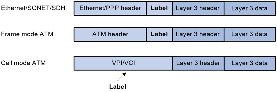
As shown in Figure 2, if the link layer protocol has a label field like VPI/VCI in ATM, the MPLS label is encapsulated in that field. In other cases, it is inserted between the link layer header and the network layer header. As such, an MPLS label can be supported by any link layer protocol.
Figure 2 Place of a label in a packet
|
|
NOTE: The device does not support the ATM cell mode. |
LSR
A label switching router (LSR) is capable of label advertising and switching. LSR is a fundamental component on an MPLS network. All LSRs support MPLS. A network consisting of LSRs is called an MPLS domain.
LSP
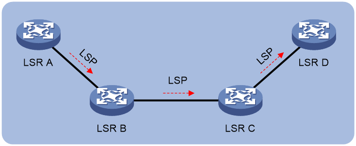
A label switched path (LSP) is the path along which packets of an FEC travel through an MPLS network.
An LSP is a unidirectional packet forwarding path. Two neighboring LSRs are called the upstream LSR and downstream LSR along the direction of an LSP. As shown in Figure 3, LSR B is the downstream LSR of LSR A, and LSR A is the upstream LSR of LSR B.
LFIB
The Label Forwarding Information Base (LFIB) on an MPLS network functions like the Forwarding Information Base (FIB) on an IP network. When an LSR receives a labeled packet, it searches the LFIB to obtain information for forwarding the packet. The information includes the label operation type, the outgoing label value, and the next hop.
Control plane and forwarding plane
An MPLS node consists of a control plane and a forwarding plane.
· Control plane—Assigns labels, distributes FEC-label mappings to neighbor LSRs, creates the LFIB, and establishes and removes LSPs.
· Forwarding plane—Forwards packets according to the LFIB.
Architecture of MPLS
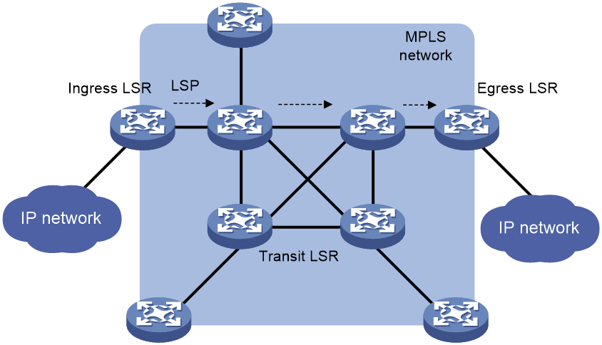
An MPLS network has the following types of LSRs:
· Ingress LSR—Ingress LSR of packets. It labels packets entering into the MPLS network.
· Transit LSR—Intermediate LSRs in the MPLS network. The transit LSRs on an LSP forward packets to the egress LSR according to labels.
· Egress LSR—Egress LSR of packets. It removes labels from packets and forwards the packets to their destination networks.
Transit LSRs forward packets according to the labels of the packets in the MPLS network and edge LSRs deal with the conversion between MPLS and IP.
Figure 4 MPLS network architecture
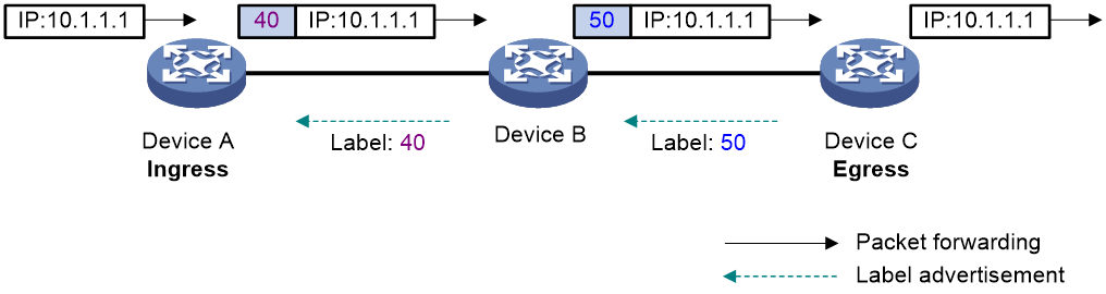
An LSP is a tunnel from the ingress to egress node. The process of establishing an LSP is to bind the FEC with a label on each LSR involved and advertise the binding to adjacent LSRs, so as to establish an LFIB entry on each LSR along the optimal route. Of two neighboring LSRs along an LSP, the one sending packets is called the upstream LSR and the one receiving the packets is called the downstream LSR. In Figure 5, Device A is the upstream LSR of Device B, while Device B is the upstream LSR of Device C. A downstream LSR assigns a label to an FEC, and then advertises the label-FEC binding to its upstream LSR, which saves the label-FEC binding.
In an MPLS domain, packets of an FEC travel from the ingress to the egress along an LSP. When an upstream LSR receives a packet of an FEC, it encapsulates the packet with the label assigned to the FEC by the downstream LSR, and then forwards the packet to the downstream LSR.
Figure 5 Label advertisement and packet forwarding diagram
LSP establishment
An LSP for an FEC is established when labels are assigned to the FEC and label forwarding entries are created on the LSRs of the LSP. LSPs include static and dynamic LSPs.
Static LSP
To establish a static LSP, you must configure an LFIB entry on each LSR along the LSP. Establishing static LSPs consumes fewer resources than establishing dynamic LSPs, but static LSPs cannot automatically adapt to network topology changes. Therefore, static LSPs are suitable for small-scale networks with simple, stable topologies.
Dynamic LSP
A dynamic LSP is established by a label distribution protocol (also called an MPLS signaling protocol). A label distribution protocol classifies FECs, distributes FEC-label mappings, and establishes and maintains LSPs.
A dynamic LSP is established in the following steps:
1. A downstream LSR classifies FECs according to destination addresses.
2. The downstream LSR assigns a label for each FEC, and distributes the FEC-label binding to its upstream LSR.
3. The upstream LSR establishes an LFIB entry for the FEC according to the binding information.
After all LSRs along the LSP establish an LFIB entry for the FEC, a dynamic LSP is established for the packets of this FEC.
Figure 6 Dynamic LSP establishment
LSP Nesting
Multiple hops may exist between the neighboring upstream LSR and downstream LSR on an LSP. MPLS allows establishing a new LSP between the upstream LSR and downstream LSR, and thus the two LSRs are respectively the start point and end point of the new LSP. For example, in Figure 7, LSP 1 (R1→R2→R3→R4) is the level 1 LSP tunnel and LSP 2 (R2→R21→R22→R23→R3) is the level 2 LSP tunnel.
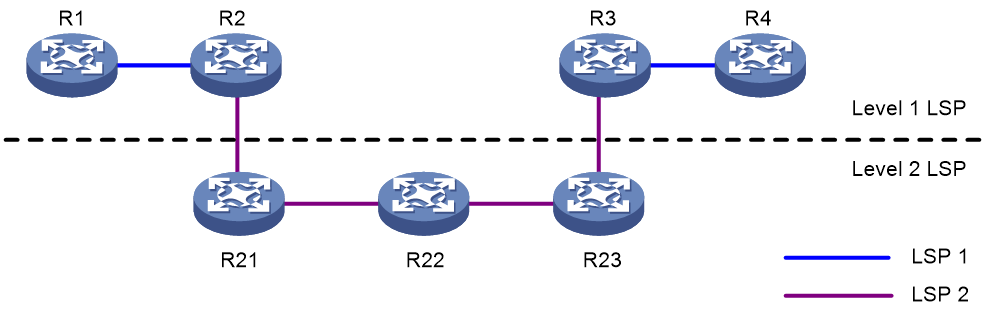
MPLS implements LSP nesting by inserting multiple levels of labels (label stack) in a packet. A label stack organizes labels in last-in first-out (LIFO) mode and MPLS processes the labels from the top label in the stack. The ingress and egress of each tunnel perform Push and Pop operations respectively on the top of a stack. In Figure 7, R1 pushes a level 1 label for a packet and R2 pushes a level 2 label for the packet; R3 pops the level 2 label of the packet and R4 pops the level 1 label of the packet. LSP 2 forwards the packet according to the level 2 labels and LSP 1 forwards the packet according to the level 1 labels.
MPLS has no limit to the depth of a label stack. For a label stack with a depth of m, the label at the bottom is of level 1, while the label at the top has a level of m. An unlabeled packet can be considered as a packet with an empty label stack, that is, a label stack whose depth is 0.
MPLS forwarding
MPLS forwarding process
Figure 8 MPLS forwarding process diagram
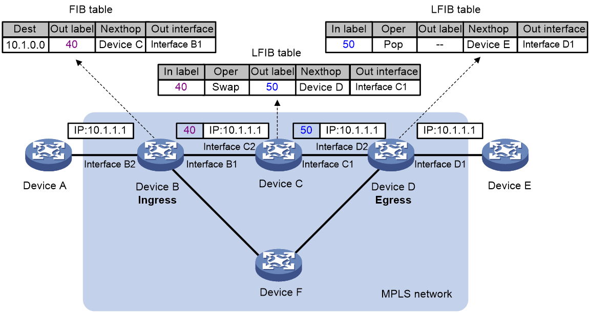
As shown in Figure 8, in an MPLS domain, a packet is forwarded in the following procedure:
1. Device B (the ingress LSR) receives a packet carrying no label. Device B determines the FEC according to the destination address of the packet, adds label 40 in the packet, and then forwards the labeled packet from outgoing interface (Interface B1) to the next-hop LSR (Device C).
2. Device C looks up the label forwarding entry according to the packet label (40), replaces label 40 with a new label (50), and then forwards the labeled packet from outgoing interface (Interface C1) to the next-hop LSR (Device D).
PHP
In an MPLS network, an egress node receives a labeled packet, looks up the label forwarding table, pops the label of the packet, and then performs the next level label forwarding for the packet or performs IP forwarding. That is, an egress node needs to look up the forwarding table twice before it can forward a packet: looks up the label forwarding table twice, or looks up the label forwarding table once and the IP forwarding table once.
On a relatively simple MPLS application network, after the penultimate hop forwards the packet to the egress, the label at the top of the stack is useless. The egress can directly perform the next level forwarding without the first look up of the forwarding table. In this case, the penultimate hop popping (PHP) feature can pop the label at the penultimate node, relieving the egress of the label operation burden and improving the packet processing capability of the MPLS network.
A PHP-capable egress node can send either of the following null labels to the penultimate node:
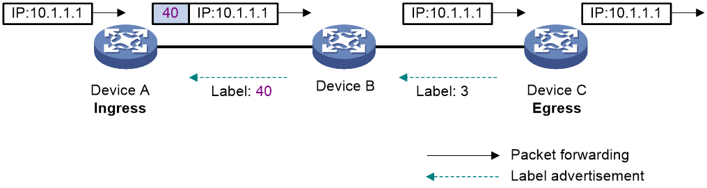
· Implicit null label—The value of an implicit null label is 3. If an incoming packet matches an LFIB entry containing the implicit null label, the penultimate node pops the top label and forwards the packet to the egress node. The egress node forwards the packet based on the header of its next layer.
Figure 9 Implicit null label
· Explicit null label—The value of an explicit null label is 0. Sometimes, the egress node must use the TC field in the label to perform QoS. To keep the TC information, you can configure the egress node to send the penultimate node an explicit null label. If an incoming packet matches an LFIB entry containing the explicit null label, the penultimate hop replaces the top label value with value 0, and forwards the packet to the egress node. When the egress node receives the packet, it does not look up the LFIB table for the label of 0. The egress mode gets the TC information from the label, pops the label, and then forwards the packet based on the header of its next layer.
Label distribution protocols
The label distribution protocols are MPLS signaling protocols, responsible for FEC classification, label distribution, and LSP establishment and maintenance. The label distribution protocols include protocols designed specifically for label distribution, such as LDP, and the protocols extended to support label distribution, such as BGP and RSVP-TE.
|
|
NOTE: In this document, “the label distribution protocols” represents generally all protocols used for label distribution, and “LDP” refers specifically to the Label Distribution Protocol defined in RFC 5036. |
· LDP determines each hop of an LSP according to the routing table. The LSP path is the same as the route path for the original IP packets. The LSP established by LDP cannot balance the traffic on each link of the network. It only establishes the virtual connection.
· RSVP-TE carries parameters such as bandwidth, explicit route, and color and establishes an LSP that satisfies these constraints through the constraint-based routing algorithm, so that it can implement traffic engineering and QoS. RSVP-TE is an extension to the Resource Reservation Protocol (RSVP) and is raw IP based. As raw IP transmission is unreliable, RSVP-TE needs to refresh the LSP state periodically.
· Extended BGP is mainly applicable to MPLS L3VPN networks. It can assign inner labels for VPNs and establish an inter-AS carrier tunnel for an MPLS VPN.
This document takes LDP as an example to introduce the working procedure of a label distribution protocol.
Basic concepts of LDP
The LDP protocol dictates the messages to be used in label distribution and the related processes. Using LDP, LSRs can map network layer routing information to data link layer switching paths directly and further establish LSPs. LSPs can be established between both neighboring LSRs and LSRs that are not directly connected, making label switching possible at all transit nodes on the network.
LDP session
Two LSRs establish a TCP-based LDP session to exchange FEC-label mappings.
LDP peer
Two LSRs that use LDP to exchange FEC-label mappings are LSR peers.
Label space and LDP identifier
A scope of labels that can be assigned to FECs is called a label space.
· A per interface label space is interface-specific, that is, each interface of an LSR has a specific label space.
· A per-platform label space is for an entire LSR.
The device supports only the per-platform label space.
An LDP identifier (LDP ID) is used to identify an LSR label space. It is a six-byte numerical value in the format of <LSR ID>:<Label space ID>, where LSR ID is four-byte long and label space ID is two-byte long.
A label space ID of 0 means that the label space is per platform. A label space ID other than 0 means that the label space is per interface.
LDP uses the same LDP ID format on IPv4 and IPv6 networks. An LDP ID must be globally unique.
FEC-label mapping
An LSR assigns a label for an FEC and advertises the FEC-label mapping, or FEC-label binding, to its peers in a Label Mapping message.
LDP messages
LDP mainly uses the following types of messages:
· Discovery messages—Declare and maintain the presence of LSRs, such as Hello messages.
· Session messages—Establish, maintain, and terminate sessions between LDP peers, such as Initialization messages used for parameter negotiation and Keepalive messages used to maintain sessions.
· Advertisement messages—Create, alter, and remove FEC-label mappings, such as Label Mapping messages used to advertise FEC-label mappings.
· Notification messages—Provide advisory information and notify errors, such as Notification messages.
LDP uses UDP to transport discovery messages for efficiency, and uses TCP to transport session, advertisement, and notification messages for reliability.
Label distribution and control
Label advertisement modes
LDP advertises label-FEC mappings in one of the following ways:
· Downstream Unsolicited (DU) mode—Distributes FEC-label mappings to the upstream LSR, without waiting for label requests. The device supports only the DU mode.
· Downstream on Demand (DoD) mode—Sends a label request for an FEC to the downstream LSR. After receiving the label request, the downstream LSR distributes the FEC-label mapping for that FEC to the upstream LSR.
Figure 10 Label advertisement modes
|
|
NOTE: To successfully establish an LSP, a pair of upstream and downstream LSRs must use the same label advertisement mode. |
Label distribution control
LDP controls label distribution in one of the following ways:
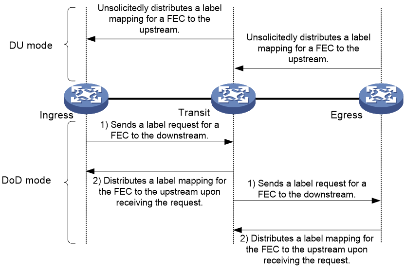
· Independent label distribution—Distributes an FEC-label mapping to an upstream LSR at any time. An LSR might distribute a mapping for an FEC to its upstream LSR before it receives a label mapping for that FEC from its downstream LSR. As shown in Figure 11, in DU mode, each LSR distributes a label mapping for an FEC to its upstream LSR whenever it is ready to label-switch the FEC. The LSRs do not need to wait for a label mapping for the FEC from its downstream LSR. In DoD mode, an LSR distributes a label mapping for an FEC to its upstream LSR after it receives a label request for the FEC. The LSR does not need to wait for a label mapping for the FEC from its downstream LSR.
Figure 11 Independent label distribution control mode
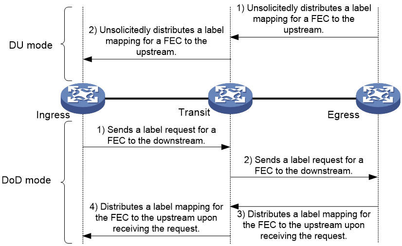
· Ordered label distribution—Distributes a label mapping for an FEC to its upstream LSR only after it receives a label mapping for that FEC from its downstream LSR unless the local node is the egress node of the FEC. As shown in Figure 10, in DU mode, an LSR distributes a label mapping for an FEC to its upstream LSR only if it receives a label mapping for the FEC from its downstream LSR. In DoD mode, when an LSR (Transit) receives a label request for an FEC from its upstream LSR (Ingress), it continues to send a label request for the FEC to its downstream LSR (Egress). After the transit LSR receives a label mapping for the FEC from the egress LSR, it distributes a label mapping for the FEC to the ingress LSR.
Label retention mode
The label retention mode specifies whether an LSR maintains a label mapping for an FEC learned from a neighbor that is not its next hop.
· Liberal label retention—Retains a received label mapping for an FEC regardless of whether the advertising LSR is the next hop of the FEC. This mechanism allows for quicker adaptation to topology changes, but it wastes system resources because LDP has to keep useless labels.
· Conservative label retention—Retains a received label mapping for an FEC only when the advertising LSR is the next hop of the FEC. This mechanism saves label resources, but it cannot quickly adapt to topology changes.
The device only supports liberal label retention.
LDP operation
LDP can operate on an IPv4 or IPv6 network, or a network where IPv4 coexists with IPv6. LDP operates similarly on IPv4 and IPv6 networks.
LDP operates in the following phases: discovering and maintaining LDP peers, establishing and maintaining LDP sessions, and establishing LSPs.
Discovering and maintaining LDP peers
LDP-enabled LSRs discover and maintain LDP peer relationships through Hello messages.
LDP discovers peers in the following ways:
· Basic Discovery—Discovers directly connected LSRs.
¡ On an IPv4 network, an LSR sends IPv4 Link Hello messages to multicast address 224.0.0.2. All directly connected LSRs can discover the LSR and establish an IPv4 Link Hello adjacency.
¡ On an IPv6 network, an LSR sends IPv6 Link Hello messages to FF02:0:0:0:0:0:0:2. All directly connected LSRs can discover the LSR and establish an IPv6 Link Hello adjacency.
¡ On a network where IPv4 and IPv6 coexist, an LSR sends both IPv4 and IPv6 Link Hello messages to each directly connected LSR and keeps both the IPv4 and IPv6 Link Hello adjacencies with a neighbor.
· Extended Discovery—Sends LDP IPv4 Targeted Hello messages to an IPv4 address or LDP IPv6 Targeted Hello messages to an IPv6 address. The destination LSR can discover the LSR and establish a hello adjacency. This mechanism is typically used in LDP session protection, LDP over MPLS TE, MPLS L2VPN, and VPLS.
LDP can establish two hello adjacencies with a directly connected neighbor through both discovery mechanisms. It sends Hello messages at the hello interval to maintain a hello adjacency. If LDP receives no Hello message from a hello adjacency before the hello hold timer expires, it removes the hello adjacency.
Establishing and maintaining LDP sessions
LDP establishes a session to a peer in the following steps:
1. Establishes a TCP connection to the neighbor.
On a network where IPv4 and IPv6 coexist, LDP establishes an IPv6 TCP connection. If LDP fails to establish the IPv6 TCP connection, LDP tries to establish an IPv4 TCP connection.
2. Negotiates session parameters such as LDP version, label distribution method, and Keepalive timer, and establishes an LDP session to the neighbor if the negotiation succeeds.
After a session is established, LDP sends LDP PDUs (an LDP PDU carries one or more LDP messages) to maintain the session. If no information is exchanged between the LDP peers within the Keepalive interval, LDP sends Keepalive messages at the Keepalive interval to maintain the session. If LDP receives no LDP PDU from a neighbor before the keepalive hold timer expires, or the last hello adjacency with the neighbor is removed, LDP terminates the session.
LDP can also send a Shutdown message to a neighbor to terminate the LDP session.
An LSR can establish only one LDP session to a neighbor. The session can be used to exchange IPv4 and IPv6 FEC-label mappings at the same time.
Establishing LSPs
LDP classifies FECs according to destination IP addresses in IP routing entries, creates FEC-label mappings, and advertises the mappings to LDP peers through LDP sessions. After an LDP peer receives an FEC-label mapping, it uses the received label and the label locally assigned to that FEC to create an LFIB entry for that FEC. When all LSRs (from the Ingress to the Egress) establish an LFIB entry for the FEC, an LSP is established exclusively for the FEC.
Figure 12 Dynamically establishing an LSP
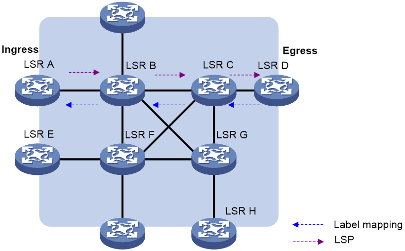
Figure 12 shows the LSP establishment process when the DU mode and ordered mode are used:
1. When network routes change, if the egress node (LSR D) detects a new destination in its routing table and the address does not belong to any existing FEC, LSR D will establish a new FEC for this destination address.
2. If LSR D has available labels, it assigns a label to the FEC and then advertises the FEC-label mapping to LSR C.
3. After receiving the label mapping, LSR C checks whether LSR D, which sends the label mapping, is the next hop of the FEC. If yes, LSR C will add a corresponding entry in its label forwarding table, assigns a label to the FEC and advertises the label mapping upstream to LSR B.
4. Alike, when receiving the label mapping from LSR C, LSR B checks whether LSR C, which sends the label mapping, is the next hop of the FEC. If yes, LSR B will add a corresponding entry in its label forwarding table, assigns a label to the FEC and advertises the label mapping upstream to LSR A.
5. After receiving the label mapping, LSR A, the ingress, checks whether LSR B, which sends the label mapping, is the next hop of the FEC. If yes, LSR A will add a corresponding entry in its label forwarding table.
By this time, an LSP, LSR A→LSR B→LSR C→LSR D, is established. Packets of this FEC received on LSR A will be forwarded along this LSP.
Application scenarios
MPLS, integrating the Layer 2 switching technology and Layer 3 routing technology, was initially proposed to improve forwarding speed. However, with the development of Application-Specific Integrated Circuit (ASIC), packet forwarding speed is no longer the bottleneck of network development. This makes MPLS not so competitive in improving forwarding speed.
However, MPLS integrates IP network’s strong Layer 3 routing function and effective forwarding mechanism of Layer 2. In the forwarding plane, MPLS is connection-oriented, which is similar to the forwarding mode on Layer 2 networks. These features of MPLS enable seamless integration of IP with ATM or frame relay, providing better solutions for VPN, TE, and QoS applications.
MPLS-based VPN
Traditional VPNs use tunneling protocols such as GRE, L2TP, and PPTP to transmit data of private networks over the public network. MPLS VPNs use LSPs to tunnel the private data.
Different private network branches can be connected through LSPs to form a unified virtual private network.
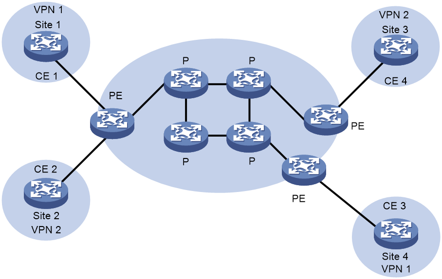
As shown in Figure 13, an MPLS VPN network consists of three kinds of devices:
· Customer edge (CE) device—A CE resides on a customer network and has one or more interfaces directly connected with service provider networks. It neither can "sense" the existence of any VPN nor needs to support MPLS.
· Provider edge (PE) device—A PE resides on a service provider network and connects one or more CEs to the network. On an MPLS network, all VPN processing occurs on the PEs. A PE manages VPN users, establishes LSP connections with other PEs, and distributes routes between the VPN branches.
· Provider (P) device—A P device is a backbone device on a service provider network. It is not directly connected with any CE. It only needs to support basic MPLS forwarding capability. It performs MPLS forwarding for VPN packets according to only the outer layer labels, and does not participate in VPN processing.
MPLS VPNs fall into MPLS L3VPNs and MPLS L2VPNs:
· MPLS L3VPN—A PE-based Layer 3 VPN technology for service provider VPN solutions. It uses MP-BGP to advertise VPN routes and uses MPLS to forward VPN packets on service provider backbones.
· MPLS L2VPN—Provides Layer 2 VPN services on the MPLS network. It allows carriers to transfer Layer 2 user data transparently on the MPLS network. For users, the MPLS network is a Layer 2 switched network and can be used to establish Layer 2 connections between nodes.
MPLS-based TE
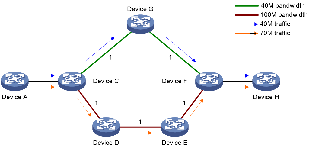
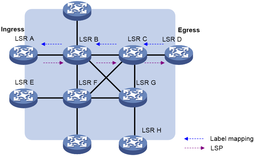
TE can make best utilization of network resources and avoid non-even load distribution by monitoring the traffic and traffic load on each network elements in real time and dynamically tuning traffic management attributes, routing parameters, and resources constraints. As shown in Figure 14, there are two paths between Device A and Device H. One path is Device A—Device C—Device G—Device F—Device H, with bandwidth being 40 M, and the other is Device A—Device C—Device D—Device E—Device F—Device H, with the bandwidth being 100 M. Traffic engineering can allocate traffic to the two paths according to their bandwidths to avoid link congestion. For example, two services from Device A to Device H have traffic of 40 M and 70 M respectively. Traffic engineering can allocate the former service to the path with 40-Mbps bandwidth, and the latter to the path with 100-Mbps bandwidth.
MPLS is better than IGPs in implementing traffic engineering for the following:
· MPLS supports explicit routes.
· Label-based forwarding is easy to manage and maintain compared with traditional IP forwarding.
· MPLS TE uses less system resources compared with other traffic engineering implementations.
MPLS TE combines the MPLS technology and traffic engineering. It reserves resources by establishing LSP tunnels to specific destinations. This allows traffic to bypass congested nodes to achieve appropriate load distribution. MPLS TE delivers these benefits:
· Reserve resources by establishing LSP tunnels to specific destinations, ensuring quality of service.
· An LSP tunnel has many attributes such as priority and bandwidth, making it easy to be managed.
· In case an LSP tunnel fails, MPLS TE can provide LSP backup and Fast Reroute (FRR).
· LSP establishment costs little resource, and therefore will not impact normal services.
· Cooperating with ITU-T Y.1711-based MPLS Operation, Administration and Maintenance (OAM) and ITU-T Y.1720-based protection switchover, MPLS TE can detect the connectivity of the entire LSP tunnel and, once a failure is detected, performs a protection switchover.
These features of MPLS TE make it a very attractive traffic engineering solution. Through the MPLS TE technology, service providers can make full use of the network resources and provide diversified services. At the same time, they can optimize the network resources and manage the network more scientifically.
MPLS-based QoS
It is required to implement QoS on the IP network to provide the voice and video services with bandwidth guarantee and low time delay. Diff-Serv is a commonly used QoS mechanism on the IP network.
The Diff-serv model maps a service to a certain service class at the network edge according to the QoS requirement of the service. The Differentiated Services Code Point (DSCP) field in an IP packet identifies the service class of the packet uniquely. Then, each node in the backbone network performs the preset service policies according to the field to ensure the corresponding QoS.
The QoS classification in Diff-Serv is very similar to the MPLS label distribution mechanism. In fact, the MPLS-based Diff-Serv is implemented by integrating the DSCP distribution into the MPLS label distribution. The Exp field in a label carries the DSCP information.
MPLS-based 6PE
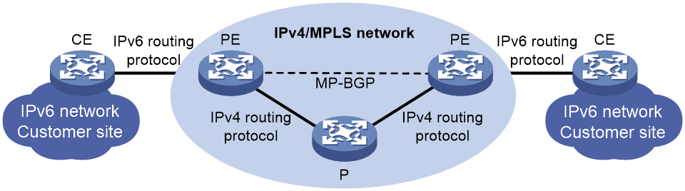
As shown in Figure 15, in an MPLS-based 6PE network:
1. A PE and a CE exchange IPv6 routing information through an IPv6 routing protocol.
2. PEs exchange IPv6 routing information using MP-BGP and allocate MPLS labels for IPv6 prefixes.
3. A PE and P in the IPv4 backbone exchange routing information through an IPv4 routing protocol and an LSP is established between the PEs through MPLS.
Figure 16 6PE packet forwarding process
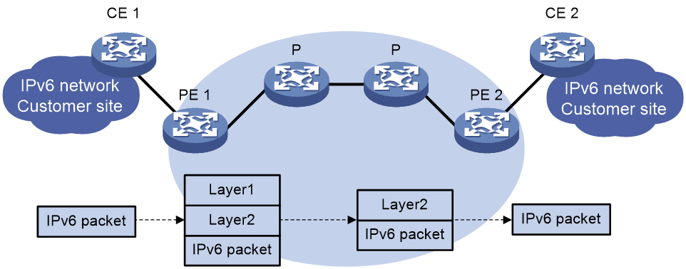
In an MPLS-based 6PE network, an IPv6 packet is forwarded in the procedure shown in Figure 16. The IPv6 packet needs to carry two layers of labels to travel through the IPv4 backbone. The inner layer (layer 2) label is the label assigned to the IPv6 prefix, and the outer layer (layer 1) label is the LSP label used between PEs.
References
· RFC 3031, Multiprotocol Label Switching Architecture
· RFC 3032, MPLS Label Stack Encoding
· RFC 5036, LDP Specification
· RFC 3034, Use of Label Switching on Frame Relay Networks Specification
· RFC 3035, MPLS using LDP and ATM VC Switching
· RFC 2547, BGP/MPLS VPNs
· RFC 2283, Multiprotocol Extensions for BGP-4
· RFC 2430, A Provider Architecture for Differentiated Services and Traffic Engineering (PASTE)
· RFC 2702, Requirements for Traffic Engineering Over MPLS
· RFC 4090, Fast Reroute Extensions to RSVP-TE for LSP Tunnels