- Released At: 12-05-2025
- Page Views:
- Downloads:
- Table of Contents
- Related Documents
-
|
|
|
|
|
Ethernet OAM Technology White Paper |
|
|
|
|
Copyright © 2021 New H3C Technologies Co., Ltd. All rights reserved.
No part of this manual may be reproduced or transmitted in any form or by any means without prior written consent of New H3C Technologies Co., Ltd.
Except for the trademarks of New H3C Technologies Co., Ltd., any trademarks that may be mentioned in this document are the property of their respective owners.
This document provides generic technical information, some of which might not be applicable to your products.
The information in this document is subject to change without notice.
Contents
Hierarchical implementation of Ethernet OAM
EFM OAM connection establishment
Technical characteristics of Comware-based EFM OAM implementation
Technical characteristics of Comware-based CFD implementation
Fast continuity check with alternative CPUs
Collaboration between Smart Link and CC of CFD
Overview
Background
With features such as ease of use and low price, Ethernet has gradually become the major underlying technology for today’s local area networks (LANs). In recent years, with the emergence of Gigabit Ethernet and 10-Gigabit Ethernet, network operators, network device vendors, and standard organizations are pushing Ethernet to metropolitan area networks (MANs) and wide area networks (WANs) as well.
Ethernet was initially designed for LANs, which can provide high reliability and stability by themselves. For this reason, no management or maintenance mechanism was developed for Ethernet in the beginning. As the link lengths and sizes of MANs and WANs grow rapidly, the absence of an effective management and maintenance mechanism for Ethernet has been seriously hindering the implementation of Ethernet in MANs and WANs. Implementing Operation, Administration and Maintenance (OAM) on Ethernet networks has now become an urgent issue. Ethernet OAM can effectively promote your management and maintenance capabilities over Ethernet networks, guaranteeing the stability of the networks.
Hierarchical implementation of Ethernet OAM
Ethernet OAM is implemented hierarchically. As shown in Figure 1, Ethernet OAM operates at two levels:
· Link-level Ethernet OAM that operates on Ethernet links connecting PEs, CEs, and customer devices (also referred to as the "last mile") and monitors the status of links connecting the customer networks and service provider networks.
· Network-level Ethernet OAM that operates on the access/distribution layer, monitors the connectivity of the entire network, and locates connectivity faults on the network.
Figure 1 Hierarchical implementation of Ethernet OAM
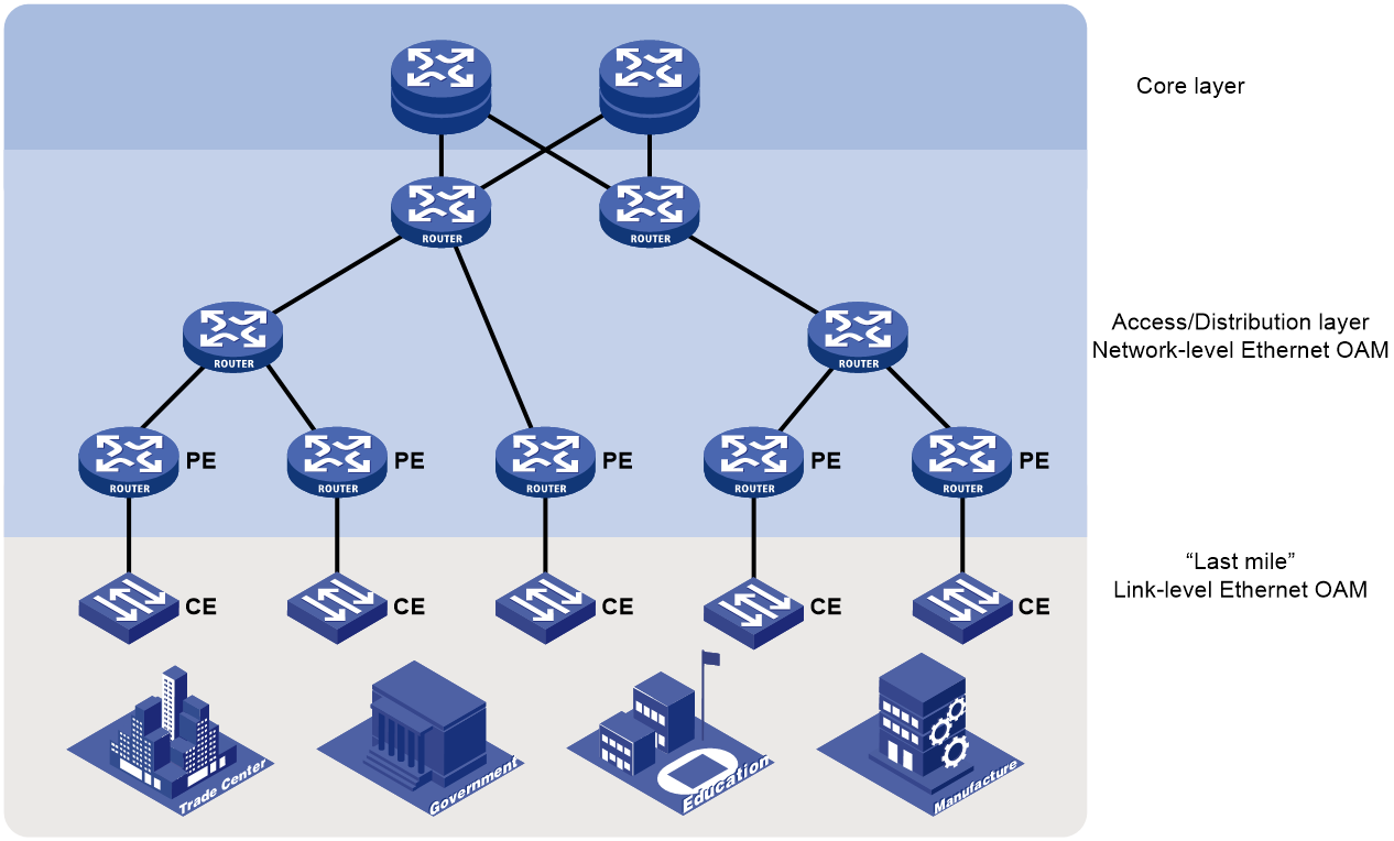
Table 1 gives details about the two Ethernet OAM protocols.
Table 1 Typical Ethernet OAM protocols
|
Protocol name |
Application level |
Underlying standard |
Description |
|
Ethernet in the First Mile OAM (EFM OAM) |
Link level |
IEEE 802.3ah |
Applies to links between directly connected devices and provides functions such as link performance monitoring, fault detection and alarming, and loop detection |
|
Connectivity Fault Detection (CFD) |
Network level |
IEEE 802.1ag |
Also called CFM and mainly used to check link connectivity, detect connectivity faults, and locate faults on Layer 2 networks |
The following parts of this document describe EFM OAM and CFD respectively.
EFM OAM implementation
Concepts
OAM entities
A port with EFM OAM enabled is called an EFM OAM entity, or an OAM entity.
OAMPDUs
EFM OAM works on the data link layer. It reports link status by exchanging OAM protocol data units (OAMPDUs) between network devices, thus helping the network administrators effectively manage the network.
Figure 2 Formats of different types of OAMPDUs
The fields in an OAMPDU are described as follows:
Table 2 Description of the fields in an OAMPDU
|
Field |
Description |
|
Dest addr |
Destination MAC address of the OAMPDU. It is a slow protocol multicast address: 0180c2000002. As slow protocol packets cannot be forwarded by bridges, EFM OAMPDUs cannot be forwarded traversing multiple hops, regardless of whether OAM is enabled. |
|
Source addr |
Source MAC address of the OAMPDU. It is the MAC address of the sending port and a unicast MAC address. If the sending port has no MAC address, the bridge MAC address of the device is used. |
|
Type |
Protocol type value 0x8809 |
|
Subtype |
Protocol encapsulated in the OAMPDU, with the value of 0x03 |
|
Flags |
Status information of an EFM OAM entity |
|
Code |
Type of the OAMPDU |
Table 3 describes common EFM OAMPDUs.
|
Code |
OAMPDU type |
Function |
|
0x00 |
Information OAMPDU |
Used for exchanging state information (including the local device information, the remote device information, and customized information in the form of TLVs) between the local and remote OAM entities and maintaining OAM connections |
|
0x01 |
Event Notification OAMPDU |
Used for notifying the remote OAM entity when a fault is detected on the link connecting the local and remote OAM entities |
|
0x04 |
Loopback Control OAMPDU |
Used for link quality check and link fault location. By inserting the information used to enable/disable loopback into a loopback control OAMPDU, you can enable/disable loopback on a remote OAM entity. |
EFM OAM modes
An EFM OAM entity can operate in active mode or passive mode. Only OAM entities operating in active OAM mode can initiate EFM OAM connections, while those operating in passive mode wait and respond to the connection requests sent by their peers. EFM OAM connections cannot be established between two OAM entities both operating in passive OAM mode. Table 4 describes the capabilities of an OAM entity operating in active or passive OAM mode.
Table 4 Capabilities of an OAM entity operating in active or passive OAM mode
|
Capability |
Active OAM mode |
Passive OAM mode |
|
Initiating OAM Discovery |
Available |
Unavailable |
|
Responding to OAM Discovery |
Available |
Available |
|
Transmitting Information OAMPDUs |
Available |
Available |
|
Transmitting Event Notification OAMPDUs |
Available |
Available |
|
Transmitting Information OAMPDUs with the Data/Pad field being empty |
Available |
Available |
|
Transmitting Loopback Control OAMPDUs |
Available |
Unavailable |
|
Responding to Loopback Control OAMPDUs |
Available |
Available |
EFM OAM link error events
Two categories of link error events are defined for EFM OAM: common and critical.
Common link error events
Common link error events, as listed in Table 5, are used for link performance monitoring.
Table 5 Common link error events
|
Ethernet OAM link error events |
Description |
|
Error-symbol period link event |
Triggered when the number of symbol errors within a specific period exceeds a configured threshold. |
|
Error-frame link event |
Triggered when the number of frame errors within a specific period exceeds a configured threshold. |
|
Error-frame period link event |
Triggered when the number of frame errors within a specific number of frames exceeds a configured threshold. |
|
Error-frame seconds link event |
Triggered when the number of error seconds within a specified period exceeds a configured threshold. |
|
|
NOTE: · The system converts the period of detecting the error-frame period link events into the maximum number of 64-byte frames that a port can send within the specific period, that is, the system takes the maximum number of frames sent as the period. The maximum number of frames sent is calculated using this formula: the maximum number of frames = Interface bandwidth (bps) × error-frame period link event detection period (ms)/(64 × 8 × 1000) · If frame errors appear in a particular second, this second is called an error-frame second. |
Critical link error events
Critical link error events, as listed in Table 6, are used for remote fault detection.
Table 6 Critical link error events
|
Ethernet OAM link events |
Description |
OAMPDU transmission frequencies |
|
Link Fault |
Peer link signal is lost. |
Once per second |
|
Dying Gasp |
An unexpected fault, such as power failure, occurred. |
Non-stop |
|
Critical event |
An undetermined critical event, such as a unidirectional link, occurred. |
Non-stop |
How EFM OAM works
EFM OAM connection establishment
To implement EFM OAM functions, you must first establish EFM OAM connections. The EFM OAM connection establishment process is also known as the Discovery phase, where a local OAM entity discovers remote OAM entities and establishes sessions with them.
An EFM OAM-enabled port operating in active mode initiates the establishment of an EFM OAM connection. During this process, interconnected OAM entities exchange their EFM OAM configuration information in Information OAMPDUs and determine whether EFM OAM connections can be established.
Figure 3 Exchange of Information OAMPDUs during EFM OAM connection establishment

As shown in Figure 3, interface A of Device A is enabled with EFM OAM and operates in active OAM mode.
1. Device A sends to Device B an Information OAMPDU carrying Device A’s EFM OAM configuration information.
2. After receiving this OAMPDU, Device B compares its own EFM OAM configuration with that carried in the received OAMPDU, and then returns to Device A an Information OAMPDU, which carries the EFM OAM configuration information of both Device A and Device B, as well as a tag indicating whether Device A’s EFM OAM configuration matches its own.
3. After receiving the Information OAMPDU sent by Device B, Device A judges whether Device B’s EFM OAM configuration matches its own.
If both devices conclude that their EFM OAM configurations match, an EFM OAM connection will be established between them. After an Ethernet OAM connection is established, the EFM OAM entities periodically exchange Information OAMPDUs to check whether the Ethernet OAM connection is normal. If an OAM entity receives no Information OAMPDU within the EFM OAM connection timeout time, it considers the EFM OAM connection to be down.
Link monitoring
When a local OAM entity detects a common link error event, it sends an Event Notification OAMPDU to notify the remote OAM entity, and in the meantime, records the monitoring information in the log and reports the monitoring information to the network management system (NMS); after receiving the Event Notification OAMPDU, the remote OAM entity also records the monitoring information in the log and reports the monitoring information to the NMS. In this way, the network administrators can keep track of the network status.
Remote fault detection
When a critical link error event occurs and causes traffic interruption, the faulty OAM entity notifies its peer of the fault information (that is, the critical link error event type) through the Flags field carried in an Information OAMPDU, and in the meantime, records the fault information in the log and reports the fault information to the NMS; after receiving the Information OAMPDU, the remote OAM entity also records the fault information in the log and reports the fault information to the NMS. The network administrators can keep track of the link status by checking the log information and troubleshoot in time.
Remote loopback
With remote loopback enabled, an EFM OAM entity operating in active EFM OAM mode sends a non-OAMPDU frame to its peer. After receiving the frame, the peer sends it back on the same port. Remote loopback enables the network administrators to check the link status and locate link errors. By observing the returned frames, the network administrators can evaluate the link performance, including the packet loss, delay, and jitter.
Figure 4 How remote loopback works

As shown in Figure 4, Interface A of Device A operates in active EFM OAM mode. Enable remote loopback on Ethernet 1/1 after an EFM OAM connection is established between Device A and Device B.
1. Device A sends to Device B a Loopback Control OAMPDU that carries loopback enable information and waits for Device B to respond.
2. After receiving this OAMPDU, Device B returns to Device A an Information OAMPDU that carries information indicating loopback is enabled on Device B (With loopback enabled, Device B returns non-OAMPDU frames it receives from Device A along the original path).
3. After receiving the response, Device A sends a non-OAMPDU frame to Device B.
4. After receiving the frame, Device B returns it to Device A along the original path.
5. When Device A needs to disable remote loopback, it sends to Device B a Loopback Control OAMPDU that carries loopback disable information.
Technical characteristics of Comware-based EFM OAM implementation
After an Ethernet OAM connection is established, the interconnected EFM OAM entities exchange heartbeat packets (that is, Information OAMPDUs) at a specified interval to check whether the Ethernet OAM connection is normal. If an OAM entity receives no Information OAMPDU within the EFM OAM connection timeout time, it considers the EFM OAM connection to be down.
The IEEE 802.3ah standard specifies the heartbeat exchange interval as one second and the connection timeout time as five seconds. Based on the IEEE 802.3ah standard, Comware-based EFM OAM implementation allows you to customize the heartbeat exchange interval and connection timeout time.
CFD implementation
Concepts
Maintenance domain
A maintenance domain (MD) defines the network where CFD plays its role. The boundary of an MD is defined by some maintenance association end points (MEPs) configured on ports. An MD is identified by an MD name.
To accurately locate connectivity faults, CFD introduces eight levels (from 0 to 7) to MDs. The greater the number, the higher the level and the larger the area covered. Domains can touch or nest (if the outer domain has a higher level than the nested one) but cannot intersect or overlap. CFD PDUs from a lower-level MD will be discarded after they enter a higher-level MD, while CFD PDUs from a higher-level MD can traverse a lower-level MD; CFD PDUs from an MD cannot traverse another MD with the same CFD level.
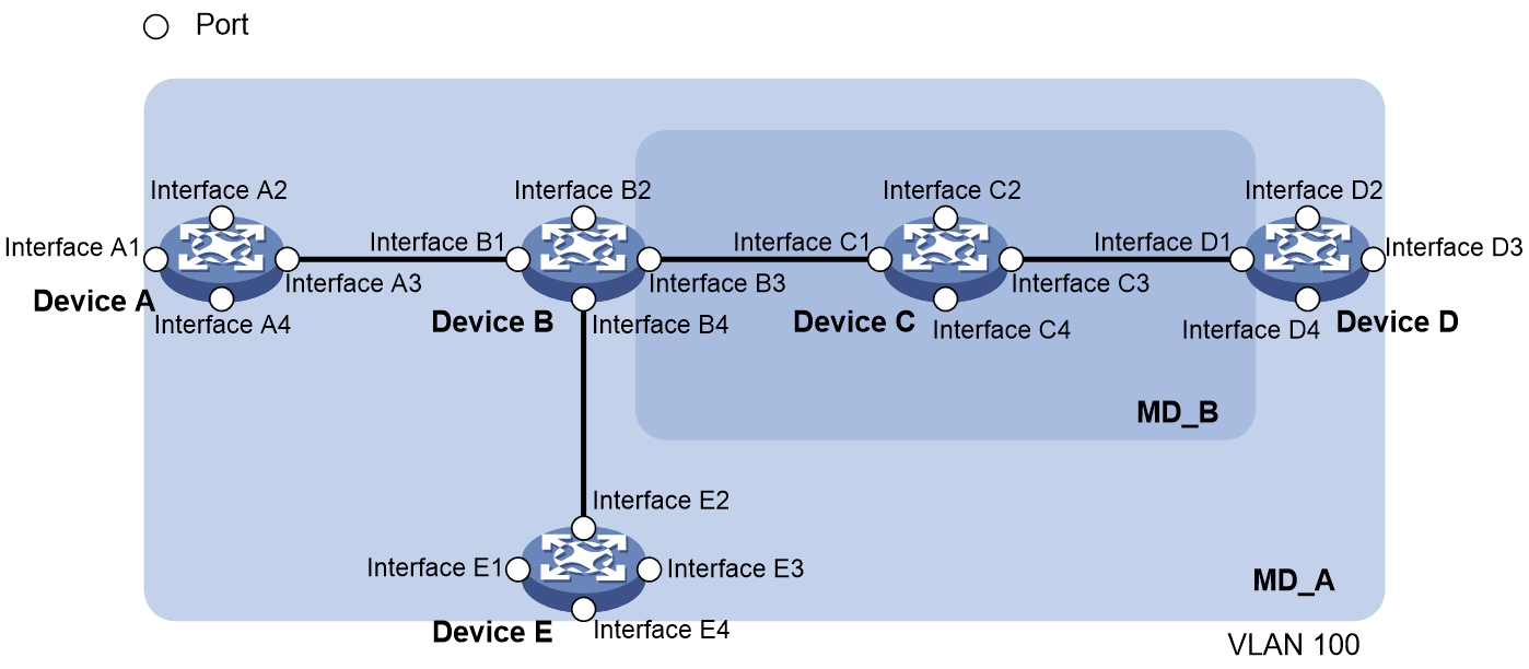
As shown in Figure 5, MD_A in light blue nests MD_B in dark blue. To detect connectivity faults in MD_A, CFD PDUs from MD_A must be able to traverse MD_B. For this reason, you need to set the level of MD_A higher than that of MD_B. In this way, you can achieve connectivity fault management (CFM) in the whole MD_A, and CFD PDUs from MD_B will not enter MD_A.
MD planning is important for network maintenance.
Maintenance association
A maintenance association (MA) is a set of maintenance points (MPs) in an MD, and is identified by the MD name + MA name combination.
Each MA serves a VLAN. Packets sent by the MPs in an MA all carry the corresponding VLAN tag. An MP can receive packets sent by other MPs in the same MA.
Maintenance point
An MP is configured on a port and belongs to an MA. MPs fall into two types: maintenance association end points (MEPs) and maintenance association intermediate points (MIPs).
MEP
Each MEP is identified by an integer called a MEP ID. The MEPs of an MD define the range and boundary of the MD. The MA and MD that a MEP belongs to define the VLAN attribute and level of the packets sent by the MEP.
The level of a MEP determines the levels of packets that the MEP can process. The packets sent from a MEP carry the level of the MEP. A MEP forwards packets of a higher level and processes packet of its own level or lower, thus ensuring that packets from a lower-level MD will not enter a higher-level MD.
MEPs fall into inward-facing MEPs and outward-facing MEPs. The direction of a MEP (outward-facing or inward-facing) determines the position of the MD relative to the port. An outward-facing MEP sends out packets through its host port, while an inward-facing MEP sends out packets through other ports on the device.
MIP
A MIP is internal to an MD. It cannot actively send out CFD PDUs; however, it can handle and respond to them. The MA and MD to which a MIP belongs define the VLAN attribute and level of the packets received by the MIP.
CFD levels
By cooperating with MEPs, a MIP can achieve a function similar to ping and tracert. Like a MEP, a MIP forwards packets of a higher level and processes packet of its own level or lower, thus ensuring that packets from a lower-level MD will not enter a higher-level MD.
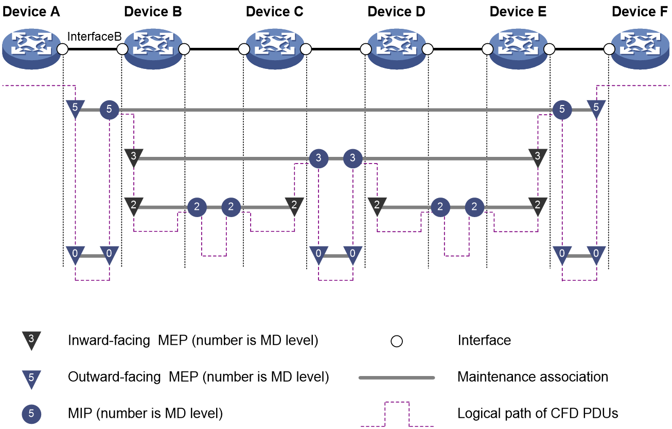
In the network as shown in Figure 6, four levels of MDs (0, 2, 3, and 5) are defined. The bigger the number, the higher the level and the larger the area covered. In this example, Interface B of Device B is configured with the following MPs: a level-5 MIP, a level-3 inward-facing MEP, a level-2 inward-facing MEP, and a level-0 outward-facing MEP.
CFD PDUs
Different types of CFD PDUs all have the same header and are recognized by the values of the fields in the header.
Figure 7 Formats of different types of CFD PDUs
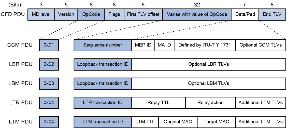
Figure 7 shows the formats of different types of CFD PDUs. The fields in a CFD PDU are described as follows:
Table 7 Description on the fields in a CFD PDU
|
Field |
Description |
|
|
MD level |
MD level, in the range 0 to 7. A larger value indicates a higher level. |
|
|
Version |
Protocol version number: 0 |
|
|
OpCode |
Type of the CFD PDU. Table 8 lists common CFD PDUs. |
|
|
Flags |
The Flags field has different meanings for different types of CFD PDUs. |
|
|
Varies with value of OpCode |
Sequence number |
The initial value of the Sequence number field is random. It increments by 1 each time the MEP sends a CCM PDU. |
|
Loopback transaction ID |
The initial value of these transaction ID fields is 0. They increment by 1 each time the MEP sends a PDU of the corresponding type (LBR/LBM/LTR/LTM). |
|
|
LTR/LTM transaction ID |
||
|
OpCode value |
Type |
Destination MAC address |
Description |
|
0x01 |
CCM PDU |
01-80-C2-00-00-3x (a multicast address; the value of x depends on the MD level, as shown in Table 9.) |
Used for continuity check (CC), and sent by MEPs |
|
0x02 |
LBR PDU |
MAC address of the loopback initiator (a unicast address) |
Used for loopback, and sent by the loopback message receiver |
|
0x03 |
LBM PDU |
Loopback destination MAC address (a unicast address) |
Used for loopback, and sent by the loopback initiator |
|
0x04 |
LTR PDU |
MAC address of the linktrace initiator (a unicast address) |
Used for linktrace, and sent by the linktrace message receiver |
|
0x05 |
LTM PDU |
01-80-C2-00-00-3y (a multicast address; the value of y depends on the MD level, as shown in Table 9.) |
Used for linktrace, and sent by the linktrace initiator |
Table 9 Values of x and y in the destination MAC address of a CFD PDU
|
MD level |
x |
y |
|
7 |
7 |
F |
|
6 |
6 |
E |
|
5 |
5 |
D |
|
4 |
4 |
C |
|
3 |
3 |
B |
|
2 |
2 |
A |
|
1 |
1 |
9 |
|
0 |
0 |
8 |
How CFD works
CFD works effectively only in properly-configured networks. Its functions are implemented through the MPs.
Continuity check
Continuity check is used to check the connectivity between MEPs. It is implemented through periodic exchange of CCM PDUs between the MEPs in an MA. The MEPs evaluate the link status based on the CCM PDU contents and the time these CCM PDUs are received. If a MEP fails to receive any CCM PDU within 3.5 sending intervals from a remote MEP, the link is considered faulty and a corresponding log is generated. You can use the loopback or linktrace function to locate the faulty segment.
Table 10 illustrates the relationship between the interval field value in CCM PDUs, the CCM PDU sending interval, and the remote MEP timeout time.
|
Interval field value |
CCM PDU sending interval |
Remote MEP timeout time |
|
1 |
10/3 milliseconds |
35/3 milliseconds |
|
2 |
10 milliseconds |
35 milliseconds |
|
3 |
100 milliseconds |
350 milliseconds |
|
4 |
1 second |
3.5 seconds |
|
5 |
10 second |
35 seconds |
|
6 |
60 seconds |
210 seconds |
|
7 |
600 seconds |
2100 seconds |
Loopback
Figure 8 Diagram for the loopback function
Similar to ping at the IP layer, loopback checks the connectivity between a local MEP and a remote MEP by sending loopback messages (LBMs, or LBM PDUs) and receiving loopback reply messages (LBRs, or LBR PDUs).

As shown in Figure 8, when loopback is performed between Device A and Device C:
1. Device A sends to Device C an LBM PDU that carries the sending time of the PDU.
2. After receiving this LBM PDU, Device C returns to Device A an LBR PDU that carries the sending and receiving time of the LBM PDU, as well as the sending time of the LBR PDU.
If within the timeout time, Device A receives an LBR PDU from Device C, loopback calculates the delay from Device A to Device C based on the time information carried in the LBR PDU; if not, Device C is considered unreachable. In addition, by continuously sending multiple LBM PDUs and observing the return of LBR PDUs, you can evaluate the packet loss rate in the network.
Linktrace
Similar to the traceroute function, linktrace identifies the path between the source and destination MEPs and locates connectivity faults by sending linktrace messages (LTMs, or LTM PDUs) and receiving linktrace reply messages (LTRs, or LTR PDUs).
Figure 9 Diagram for the linktrace function
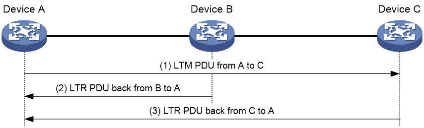
As shown in Figure 9, when linktrace is performed between Device A and Device C:
1. Device A sends to Device C an LTM PDU that carries a TTL value and the MAC address of the destination MEP (Device C).
2. After receiving the LTM PDU, Device B decrements the TTL value by 1 and then forwards it to Device C, and returns to Device A an LTR PDU that also carries a TTL value (the TTL value in the LTM PDU sent by Device A minus 1).
3. After receiving the LTM PDU from Device B, Device C returns to Device A an LTR PDU that also carries a TTL value (the TTL value in the LTM PDU forwarded by Device B minus 1). According to the destination MEP MAC address carried in the LTM PDU, Device C knows that itself is the destination MEP and hence no longer forwards the LTM PDU.
If the link between Device A and Device C fails, devices beyond the fault point will not be able to receive LTM PDUs sent by Device A or return LTR PDUs to Device A. Thus, you can locate the fault point. For example, if Device A can receive LTR PDUs returned by Device B, but not those returned by Device C, it can be concluded that the link between Device B and Device C fails.
Alarm indication signal
The alarm indication signal (AIS) is a CFD-based extension defined in ITU-T Y.1731. The AIS function suppresses the number of error alarms reported by MEPs. If a local MEP does not receive any CCM PDUs from its peer MEP within 3.5 times the CCM transmission interval, it immediately starts sending AIS PDUs. The AIS PDUs are sent periodically in the opposite direction of CCM PDUs. When the peer MEP receives the AIS PDUs, it suppresses the error alarms locally, and continues to send the AIS PDUs to the downstream MEP. If the local MEP receives CCM PDUs within 3.5 times the CCM transmission interval, it stops sending AIS PDUs and restores the error alarm function.
As shown in Figure 10, the AIS function works as follows:
1. The link between Device B and Device C becomes faulty, and the continuity check fails. Users will receive alarms.
2. Device B sends AIS PDUs to Device A, and Device C sends AIS PDUs to Device D.
3. After receiving AIS PDUs, Device A and Device D will not send alarms to users if the continuity check fails again.
By default, AIS PDUs are sent at one-second intervals. To prevent too many outgoing AIS PDUs from overloading the CPU, you can set the sending interval to one minute.
Figure 10 Diagram for the AIS function

Loss measurement
The loss measurement (LM) function measures the frame loss between a pair of MEPs, including one-way LM and two-way LM.
One-way LM
In one-way LM, the source MEP sends loss measurement message (LMM) PDUs to the target MEP. The target MEP responds with loss measurement reply (LMR) PDUs. The source MEP calculates the number of lost frames according to the counter values of the two consecutive LMR PDUs (the current LMR PDU and the previous LMR PDU). LMM PDUs and LMR PDUs are unicast frames.
As shown in Figure 7, the source MEP populates LMM PDUs with the outgoing packet count (TxFCf). After receiving an LMM PDU, the target MEP obtains the incoming packet count and outgoing packet count and replies with an LMR PDU that carries the following counters.
· TxFCf—Copied from the TxFCf field of the most recent LMM PDU received.
· RxFCf—Incoming packet count of the interface when it receives the most recent LMM PDU.
· TxFCb—Outgoing packet count of the interface when it sends an LMM PDU.
When the source MEP receives LMR PDUs (at least two groups of LMR PDUs), it calculates the number of packets lost as follows:
· Packets lost on the target MEP=|TxFCf[tc] – TxFCf[tp]| – |RxFCl[tc] – RxFCl[tp]|
· Packets lost on the source MEP=|TxFCf[tc] – TxFCf[tp]| – |RxFCl[tc] – RxFCl[tp]|
tc indicates the previous packet sending and receiving, and tp indicates the current packet sending and receiving.
As shown in Figure 11, the one-way LM function works between Device A and Device B as follows:
1. Device A sends a specific number of LMM PDUs (by default, 5 LMM PDUs) at 100-millisecond intervals. Each LMM PDU is populated with the outgoing packet count (TxFCf).
2. After receiving LMM PDUs, Device B obtains the incoming packet count and outgoing packet count and replies with an LMR PDU that carries the TxFCf, RxFCf, and TxFCb counters.
3. After receiving the first LMR PDU, Device A obtains the incoming packet count (RxFCl). Starting from receiving the second LMR PDU, Device A calculates the number of packets lost on the local end and remote end and records the calculation results. The device obtains an average value from all calculation results after the test is completed.
Accurate one-way LM test results rely on LMM PDUs and LMR PDUs sent and received, and also rely on the timeliness and accuracy of obtaining hardware counters. The device must support populating packets with the counters.

Two-way LM
In two-way LM, the source MEP sends CCMs to the target MEP. The target MEP responds with CCMs. The source MEP calculates the number of lost frames according to the counter values of the two consecutive CCMs received (the current CCM and the previous CCM).
The source MEP carries the outgoing packet count (TxFCf) in outgoing CCM PDUs. After the receiving a CCM PDU, the target MEP obtains the incoming packet count and outgoing packet count and replies with an LMR PDU that carries the following counters.
· TxFCf—Outgoing packet count of the interface when it sends a CCM PDU.
· RxFCf—Incoming packet count of the interface when it receives the most recent CCM PDU. This field is meaningless for the first CCM PDU.
· TxFCb—This field is copied from the TxFCf field of the most recent CCM PDU received. This field is meaningless for the first CCM PDU.
When the source MEP receives the next CCM PDU, the incoming packet count is RxFCb. When the source MEP receives all LMR PDUs, it calculates the number of packets lost as follows:
· Packets lost on the target MEP=|TxFCb[tc] – TxFCb[tp]| – |RxFCb[tc] – RxFCb[tp]|
· Packets lost on the source MEP=|TxFCf[tc] – TxFCf[tp]| – |RxFCf[tc] – RxFCf[tp]|
tc indicates the previous packet receiving, and tp indicates the current packet receiving.
As shown in Figure 12, the two-way LM function works between Device A and Device B as follows:
1. Device A sends a specific number of CCM PDU (by default, 5 CCM PDUs) at 100-millisecond intervals. Each CCM PDU is populated with the outgoing packet count (TxFCf).
2. After receiving CCM PDUs, Device B obtains the incoming packet count and replies with a CCM PDU that carries the TxFCf, RxFCf, and TxFCb counters.
3. After receiving the first CCM PDU, Device A obtains the incoming packet count (RxFCb). Starting from receiving the second CCM PDU, Device A calculates the number of packets lost on the local end and remote end and records the calculation results. The device obtains an average value from all calculation results after the test is completed.
Accurate one-way LM test results rely on LMM PDUs and LMR PDUs sent and received, and also rely on the timeliness and accuracy of obtaining hardware counters. The device must support populating packets with the counters.

Delay measurement
The delay measurement (DM) function measures frame delays between two MEPs, including one-way DM and two-way DM.
One-way DM
The source MEP sends a one-way delay measurement (1DM) PDU, which carries the transmission time, to the target MEP. When the target MEP receives the 1DM PDU, it does the following:
· Records the reception time.
· Calculates and records the link transmission delay and jitter (delay variation) according to the transmission time and reception time.
As shown in Figure 7, the TxTimeStampf field in a 1DM PDU is populated with the sending time of the source MEP (TxTimef), and the RxTimeStampf field is populated with the receiving time of the source MEP (RxTimef). The source MEP sends a specific number of 1DM PDUs at 100-millisecond intervals. After receiving 1DM PDUs, the target calculates the difference between the RxTimef and the TxTimef as the delay. The jitter is the difference between the longest delay and the shortest delay in this test.
One-way DM requires clock synchronization between tested devices to obtain accurate test results. Jitter testing can be performed without clock synchronization.
Two-way DM
The source MEP sends a delay measurement message (DMM) PDU, which carries the transmission time, to the target MEP. When the target MEP receives the DMM, it responds with a delay measurement reply (DMR) PDU. The DMR carries the reception time and transmission time of the DMM and the transmission time of the DMR. When the source MEP receives the DMR, it does the following:
· Records the DMR reception time.
· Calculates the link transmission delay and jitter according to the DMR reception time and DMM transmission time.
A two-way delay includes two-way link delay and two-way packet delay. The two-way link delay is the round-trip time of a packet consumed on the link. The two-way packet delay is the total round-trip time of a packet.
As shown in Figure 7, the TxTimeStampf field in a DMM PDU is populated with the sending time of the source MEP (TxTimef). After receiving a DMM PDU, the target MEP adds the TxTimef, the receiving time of the DMM PDU (RxTimef), and the receiving time of the DMR PDU (TxTimeb) to the DMR PDU.
After receiving a DMR PDU, the source MEP obtains the receiving time of the DMR PDU (RxTimef) and calculates the two-way link delay as (RxTimeb – TxTimef) – (TxTimeb – RxTimef). If the DMR PDU does not contain the receiving time of the DMM PDU (RxTimef) and the receiving time of the DMR PDU (TxTimeb), only the two-way packet delay (RxTimeb – TxTimef) can be calculated.
As shown in Figure 13, the two-way DM function works between Device A and Device B as follows:
1. Device A sends a specific number of DMM PDUs (by default, 5 DMM PDUs) at 100-millisecond intervals. Each DMM is populated with the outgoing packet count (TxTimef).
2. After receiving DMM PDUs, Device B replies with a DMR PDU that carries the TxTimef, RxTimef, and TxTimeb counters.
3. After receiving the first DMM PDU, Device A calculates the two-way delay. Starting from receiving the second CCM PDU, Device A calculates the two-way jitter and the average two-way delay.

TST
The TST function tests the bit errors between two MEPs. The source MEP sends a TST PDU, which carries the test pattern, such as pseudo random bit sequence (PRBS) or all-zero, to the target MEP. When the target MEP receives the TST PDU, it determines the bit errors by calculating and comparing the content of the TST PDU. The number of bits to be tested is 32.
The following test patterns are supported:
· All-zero value without CRC-32.
· All-zero value with CRC-32.
· Pseudo random bit sequence without CRC-32.
· Pseudo random bit sequence with CRC-32.
Technical characteristics of Comware-based CFD implementation
Fast continuity check with alternative CPUs
The CCM PDU sending interval varies from 3.3 ms to 10 minutes. A CCM PDU sending interval of 3.3 ms or so considerably impacts other services on the card where the MEP resides. On the other hand, other services’ competition for CPU resources may also affect the timely sending of CCM PDUs. To address this problem, Comware-based devices use separate assistant CPUs to send and receive CCM PDUs transmitted for fast continuity check. The check results are sent to the cards where the involved MEPs reside through the communication between primary CPUs and that between the primary and assistant CPUs.
Collaboration between Smart Link and CC of CFD
Smart Link provides link redundancy as well as fast convergence. In a dual uplink network, when the master link fails, the device automatically switches the traffic to the slave link. In this way, Smart Link improves network reliability. However, Smart Link cannot sense by itself when faults (for example, unidirectional link, misconnected fibers, and packet loss) occur on the intermediate devices or network paths, or when faults are cleared.
By using Smart Link and Track in collaboration with the continuity check (CC) function of CFD, Comware-based devices allow the detection of the connectivity faults described above as well as the detection of fault clearance. With the collaboration between Smart Link and the CC function of CCM, each MEP periodically sends out CCM PDUs. Other MEPs in the same MA acquire the status information of the remote MEPs from these CCM PDUs. When a MEP fails to receive any CCM PDU within 3.5 CCM PDU sending intervals, it considers the link to be faulty. The MEP notifies the Track module to set the Track entry associated with CC to the Negative state, and then the Track module informs Smart Link to recalculate the link status and switch over the links.
Automatic sending of LTM PDUs
Comware-based devices support the automatic sending of LTM PDUs. When a MEP fails to receive any CCM PDU within 3.5 CCM PDU sending intervals from a remote MEP, it considers the link to the remote MEP as disconnected. In this case, it automatically sends out LTM PDUs and locates the fault point by examining the returned LTR PDUs. In addition, this process is recorded, which allows the network administrators to check the fault information afterwards.
Threshold alarm
The threshold alarm function monitors the transmission performance of links, such as connectivity, delay, packet loss ratio, and bit error rate. The system generates an alarm when the transmission performance metric of a link crosses the specified upper limit or lower limit three times in succession.
Port collaboration
Port collaboration shuts down or blocks ports based on the result of link detection performed by outward-facing MEPs.
Triggering events
Port collaboration can be triggered by the following events:
· Continuity check expires.
· The link transmission delay in two-way DM reaches or exceeds the upper limit, or reaches or falls below the lower limit.
· The CCMs with the RDI flag bit set are received.
· The packet loss ratio in one-way LM reaches or exceeds the upper limit, or reaches or falls below the lower limit.
· The bit error ratio in TST reaches or exceeds the upper limit, or reaches or falls below the lower limit.
You can specify multiple triggering events for an interface. All the specified triggering events can take effect.
Triggered actions
Port collaboration takes one of the following triggered actions:
· Blocks the port by changing its link layer protocol state to DOWN (CFD). The port cannot send or receive any data packets.
· Shuts down the port by changing its physical state to CFD DOWN. The port cannot send or receive any data packets or protocol packets.
Link recovery
If a port is blocked by CFD, it can automatically come up when the link recovers, except that the block action is triggered by continual LM. To bring up the port blocked in continual LM, execute the undo cfd port-trigger slm action or cfd slm port-trigger up-delay command.
If a port is shut down by CFD, it cannot automatically come up when the link recovers. To bring up the port, you must execute the undo shutdown or undo cfd port-trigger command.
Application scenarios
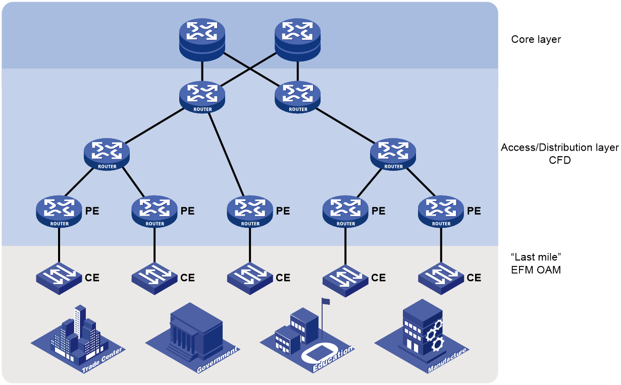
Figure 14 shows a typical application of Ethernet OAM in a metropolitan area network (MAN). In the network, Ethernet OAM is deployed by two levels:
· EFM OAM deployed on links connecting the CEs and PEs—Check the connectivity of customer access links through the periodic exchange of Information OAMPDUs between the CEs and PEs. The network administrators can judge the performance of the links connecting the CEs and PEs by observing the ratio of error frames, and perform remote loopback to check the link quality or locate connectivity faults when links fail.
· CFD deployed at the access/distribution layer—Divide devices into different MDs by the ISPs they belong to. Add devices managed by an ISP to the same MD, and divide MAs by services, allowing one MA to serve one VLAN. CFD checks the connectivity within an MA through the periodic exchange of CCM PDUs between MEPs in the MA, and generates alarms when detecting connectivity faults. The network administrators can then locate the faults with the loopback or linktrace function.
Figure 14 Network diagram from Ethernet OAM application
References
· IEEE 802.3ah: Part 3: Carrier Sense Multiple Access with Collision Detection (CSMA/CD) Access Method and Physical Layer Specifications. Amendment: Media Access Control Parameters, Physical Layers, and Management Parameters for Subscriber Access Networks
· IEEE 802.1ag: Virtual Bridged Local Area Networks Amendment 5: Connectivity Fault Management
· ITU-T Y.1731: OAM functions and mechanisms for Ethernet based networks
