- Released At: 22-02-2021
- Page Views:
- Downloads:
- Table of Contents
- Related Documents
-
|
|
|
|
|
H3C Campus Switches iNQA Best Practices |
|
|
Copyright © 2021 New H3C Technologies Co., Ltd. All rights reserved.
No part of this manual may be reproduced or transmitted in any form or by any means without prior written consent of New H3C Technologies Co., Ltd.
Except for the trademarks of New H3C Technologies Co., Ltd., any trademarks that may be mentioned in this document are the property of their respective owners.
This document provides generic technical information, some of which might not be applicable to your products.
The information in this document is subject to change without notice.
Contents
Configuring end-to-end iNQA packet loss measurement
Configuring point-to-point iNQA packet loss measurement
Configuring cross-network iNQA packet loss measurement
iNQA restrictions and guidelines
About iNQA
Background
With the development of information technology, the network is bursting with emerging network services that impose higher requirements on network performance. Among them, audio and video services are the most common and these services are highly sensitive to packet loss, delay, and jitter. A high packet loss rate and high levels of delay result in voice stuttering and erratic display, affecting user experience and even causing communication failures. When the quality of audio and video services declines, quick fault location and troubleshooting are desired.
The methods used to measure packet loss and delay can be classified into the following types:
· Indirect measurement—Uses simulated service packets to calculate packet loss and delay for service flows.
· Direct measurement—Uses real service packets directly for packet loss and delay measurement.
Traditional performance measurement technologies use the indirect measurement method, which works well for small-scale IP networks. However, in large-scale IP networks, indirect measurement fails to provide the desired fault location efficiency and accuracy and the simulated service packets incur network bandwidth overhead.
Applicable scenario
Intelligent Network Quality Analyzer (iNQA) allows you to measure network performance quickly in large-scale IP networks. iNQA supports measuring packet loss on forward, backward, and bidirectional flows. The packet loss data includes number of lost packets, packet loss rate, number of lost bytes, and byte loss rate. The measurement results help you know when and where the packet loss occurs and the event severity level. iNQA measures the service packets directly to calculate packet loss results, thus it can reflect the real network quality.
Network diagram
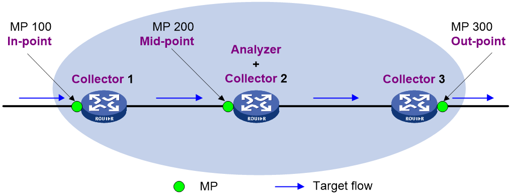
iNQA uses a network model that contains multiple collection points and a single calculation point. This model contains the following elements:
· Collector—A collector manages MPs, collects data from MPs, and reports the data to the analyzer.
· Analyzer—An analyzer collects the data from collector instances and summarizes the data.
· Target flow—Measurement object. A target flow defines a service flow to be measured and is identified by a user-defined flow matching rule. A matching rule can be any combination of the items such as source IPv4 address/segment, destination IPv4 address/segment, protocol type, source port number, and destination port number.
· MP—A measurement point counts statistics and generates data for a target flow. To measure packet loss on an interface of a collector, an MP must be bound to the interface. An MP can be the in-point (where the target flow enters the network), out-point (where the target flow leaves the network), or mid-point type.
|
|
NOTE: · To measure the packet loss for a target flow passing through a device, enable the collector function on the device. · A device can act as both a collector and an analyzer. You can enable the collector and analyzer functions on different devices or on the same device. |
Operating mechanism
1. Before the iNQA measurement starts, make sure all participating devices are time synchronized through NTP or PTP.
¡ All collectors must be time synchronized so that they use the same measurement interval for packet coloring, counting, and data reporting, ensuring accurate measurement results.
¡ Although the time inconsistency between the analyzer and a collector does not affect the measurement results, synchronize their clocks for easy management and maintenance.
2. The collector periodically collects data from MPs and reports the data to the analyzer.
3. The analyzer performs the packet loss analysis on packets of the target flow within the same period and calculates the number of lost packets (LostPkts), packet loss rate (PktLoss%), number of lost bytes (LostBytes), and byte loss rate (ByteLoss%). The following formulas are used:
¡ LostPkts = PktsIngress – PktsEgress
¡ PktLoss% = LostPkts/PktsIngress
¡ LostBytes = BytesIngress – BytesEgress
¡ ByteLoss% = LostBytes/BytesIngress
Best practices
Configuring end-to-end iNQA packet loss measurement
Network configuration
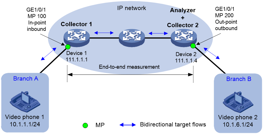
As shown in Figure 2, users at Branch A and Branch B experience stutters while making video calls through video phone 1 and video phone 2. Configure iNQA to measure the packet loss rate of the video service flows over the IP network as follows:
· Deploy Collector 1 to Device 1 and deploy Collector 1 and the analyzer to Device 2.
· Define the flow from Device 1 to Device 2 as the forward flow for packet loss measurement and configure iNQA to measure the bidirectional packet loss between MP 100 and MP 200.
· Set the packet loss upper threshold and lower threshold for the target flow to 6% and 4%, respectively. Alarms will be generated if the packet loss rate of the flow exceeds the upper threshold.
Prerequisites
1. Assign 111.1.1.1 and 111.1.1.4 to Device 1 and the analyzer, respectively. Make sure Device 1 and the analyzer can reach each other. (Details not shown.)
2. Configure NTP or PTP on Device 1 and Device 2 for clock synchronization. (Details not shown.)
Procedure
1. Configure Collector 1 on Device 1:
# Specify 111.1.1.1 as the collector ID.
<Device1> system-view
[Device1] inqa collector
[Device1-inqa-collector] collector id 111.1.1.1
# Bind the collector to the analyzer with ID 111.1.1.4.
[Device1-inqa-collector] analyzer 111.1.1.4
# Specify bit 5 in the ToS field as the flag bit.
[Device1-inqa-collector] flag loss-measure tos-bit 5
# Configure collector instance 1 to monitor the bidirectional flows between 10.1.1.0 and 10.1.6.0 on GigabitEthernet 1/0/1.
[Device1-inqa-collector] instance 1
[Device1-inqa-collector-instance-1] flow bidirection source-ip 10.1.1.0 24 destination-ip 10.1.6.0 24
[Device1-inqa-collector-instance-1] mp 100 in-point port-direction inbound
[Device1-inqa-collector-instance-1] quit
[Device1-inqa-collector] quit
[Device1] interface gigabitethernet 1/0/1
[Device1-GigabitEthernet1/0/1] inqa mp 100
[Device1-GigabitEthernet1/0/1] quit
# Enable continual packet loss measurement.
[Device1] inqa collector
[Device1-inqa-collector] instance 1
[Device1-inqa-collector-instance-1] loss-measure enable continual
[Device1-inqa-collector-instance-1] return
2. Configure Collector 2 and the analyzer on Device 2:
# Specify 111.1.1.4 as the collector ID.
<Device2> system-view
[Device2] inqa collector
[Device2-inqa-collector] collector id 111.1.1.4
# Bind the collector to the analyzer with ID 111.1.1.4.
[Device2-inqa-collector] analyzer 111.1.1.4
# Specify bit 5 in the ToS field as the flag bit.
[Device2-inqa-collector] flag loss-measure tos-bit 5
# Configure collector instance 1 to monitor the bidirectional flows between 10.1.1.0 and 10.1.6.0 on GigabitEthernet 1/0/1.
[Device2-inqa-collector] instance 1
[Device2-inqa-collector-instance-1] flow bidirection source-ip 10.1.1.0 24 destination-ip 10.1.6.0 24
[Device2-inqa-collector-instance-1] mp 200 out-point port-direction outbound
[Device2-inqa-collector-instance-1] quit
[Device2-inqa-collector] quit
[Device2] interface gigabitethernet 1/0/1
[Device2-GigabitEthernet1/0/1] inqa mp 200
[Device2-GigabitEthernet1/0/1] quit
# Enable continual packet loss measurement.
[Device2] inqa collector
[Device2-inqa-collector] instance 1
[Device2-inqa-collector-instance-1] loss-measure enable continual
[Device2-inqa-collector-instance-1] quit
[Device2-inqa-collector] quit
# Specify 111.1.1.4 as the analyzer ID.
[Device2] inqa analyzer
[Device2-inqa-analyzer] analyzer id 111.1.1.4
# Bind analyzer instance 1 to Collector 1 and Collector 2.
[Device2-inqa-analyzer] instance 1
[Device2-inqa-analyzer-instance-1] collector 111.1.1.1
[Device2-inqa-analyzer-instance-1] collector 111.1.1.4
# Set the packet loss upper limit and lower limit to 6% and 4%, respectively.
[Device2-inqa-analyzer-instance-1] loss-measure alarm upper-limit 6 lower-limit 4
# Enable the measurement function in analyzer instance 1.
[Device2-inqa-analyzer-instance-1] measure enable
[Device2-inqa-analyzer-instance-1] return
Verifying the configuration
1. Verify the configuration on Device 1:
# Display the collector configuration.
<Device1> display inqa collector
Collector ID : 111.1.1.1
Loss-measure flag : 5
Analyzer ID : 111.1.1.4
Analyzer UDP-port : 53312
VPN-instance-name : --
Current instance count : 1
# Display the configuration of collector instance 1.
<Device1> display inqa collector instance 1
Instance ID : 1
Status : Enabled
Duration : --
Description : --
Analyzer ID : --
Analyzer UDP-port : --
VPN-instance-name : --
Interval : 10 sec
Flow configuration:
flow bidirection source-ip 10.1.1.0 24 destination-ip 10.1.6.0 24
MP configuration:
mp 100 in-point inbound, GE1/0/1
2. Verify the configuration on Device 2:
# Display the collector configuration.
<Device2> display inqa collector
Collector ID : 111.1.1.4
Loss-measure flag : 5
Analyzer ID : 111.1.1.4
Analyzer UDP-port : 53312
VPN-instance-name : --
Current instance count : 1
# Display the configuration of collector instance 1.
<Device2> display inqa collector instance 1
Instance ID : 1
Status : Enabled
Duration : --
Description : --
Analyzer ID : --
Analyzer UDP-port : --
VPN-instance-name : --
Interval : 10 sec
Flow configuration:
flow bidirection source-ip 10.1.1.0 24 destination-ip 10.1.6.0 24
MP configuration:
mp 200 out-point outbound, XGE1/0/1
# Display the analyzer configuration.
<Device2> display inqa analyzer
Analyzer ID : 111.1.1.4
Protocol UDP-port : 53312
Current instance count : 1
# Display the configuration of analyzer instance 1.
<Device2> display inqa analyzer instance 1
Instance ID : 1
Status : Enable
Description : --
Alarm upper-limit : 6.000000%
Alarm lower-limit : 4.000000%
Current AMS count : 0
Collectors : 111.1.1.1
111.1.1.4
3. View the packet loss statistics on Device 2:
# On Device 2, limit the rate for flows sourced from 10.1.1.0 on the interface connected to Device 1. (Details not shown.)
# Display the iNQA packet loss statistics of analyzer instance 1.
[Device2] display inqa statistics loss instance 1
Latest packet loss statistics for forward flow:
Period LostPkts PktLoss% LostBytes ByteLoss%
159074890 0 0.000000% 0 0.000000%
159074889 0 0.000000% 0 0.000000%
159074888 0 0.000000% 0 0.000000%
159074887 13344 54.248313% 17080320 54.248313%
159074886 268288 54.249900% 343408640 54.249900%
159074885 272466 54.249727% 348756480 54.249727%
159074884 229841 45.699305% 294196480 45.699305%
159074883 0 0.000000% 0 0.000000%
159074882 0 0.000000% 0 0.000000%
Latest packet loss statistics for backward flow:
Period LostPkts PktLoss% LostBytes ByteLoss%
159074890 0 0.000000% 0 0.000000%
159074889 0 0.000000% 0 0.000000%
159074888 0 0.000000% 0 0.000000%
159074887 0 0.000000% 0 0.000000%
159074886 0 0.000000% 0 0.000000%
159074885 0 0.000000% 0 0.000000%
159074884 0 0.000000% 0 0.000000%
159074883 0 0.000000% 0 0.000000%
159074882 0 0.000000% 0 0.000000%
Configuring point-to-point iNQA packet loss measurement
Network configuration
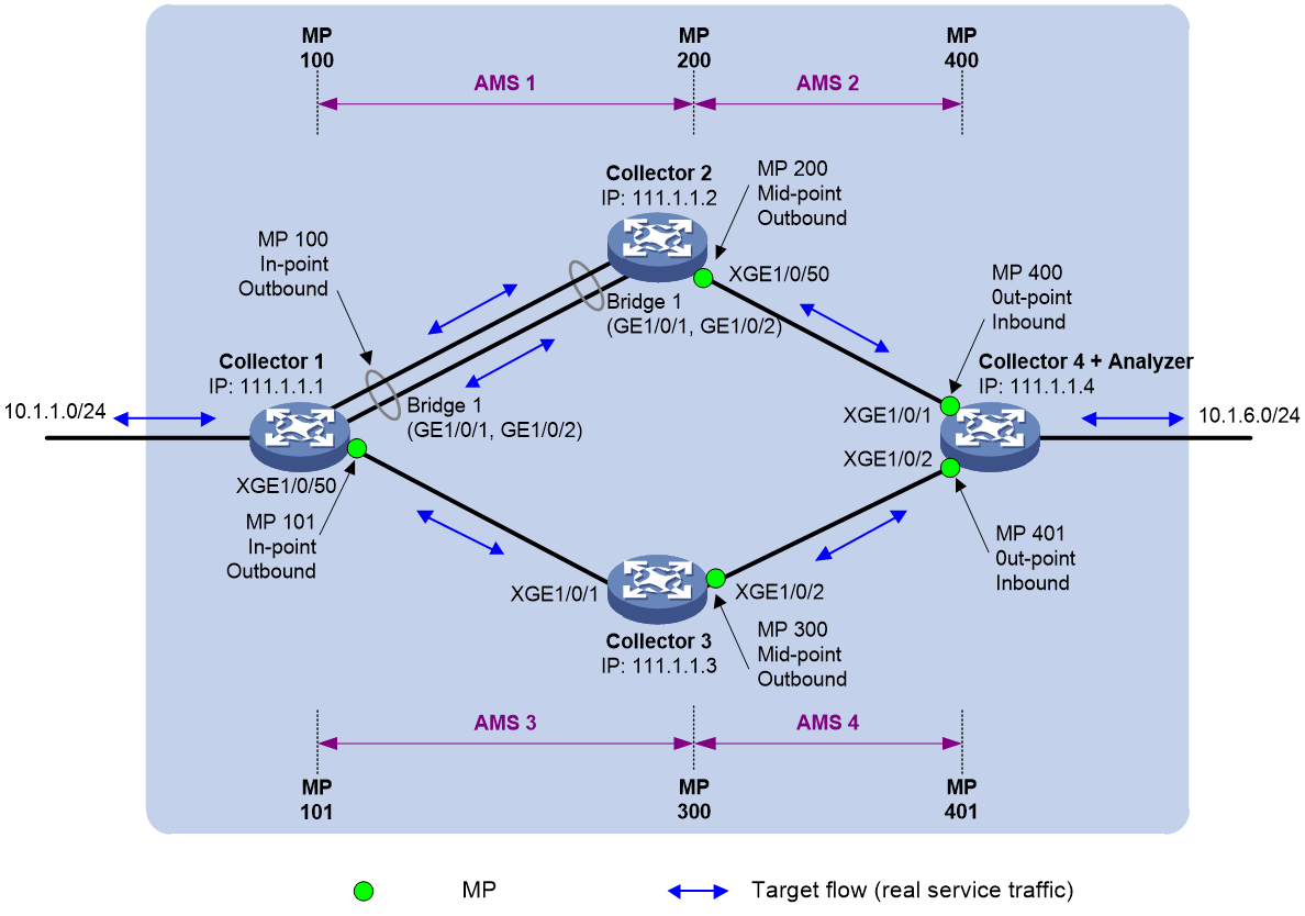
As shown in Figure 3, user 1 (with IP address 10.1.1.1) and user 2 (with IP address 10.1.6.1) experience severe stutters while making audio calls over the IP network. Configure iNQA to measure the packet loss rate of the audio service flows over the IP network as follows:
· Enable iNQA on all participating devices.
· Define the flow from Collector 1 to Collector 4 as the forward flow.
· Set the packet loss upper threshold and lower threshold for the target flow to 6% and 4%, respectively. Alarms will be generated if the packet loss rate of the flow exceeds the upper threshold.
· Run the packet loss measurement for 30 minutes.
· Measure the bidirectional packet loss rate for the flow transmitted between MP 100 and MP 400, and for the flow transmitted in AMS 1 and AMS 2.
· Measure the bidirectional packet loss rate for the flow transmitted between MP 101 and MP 401 and for the flow transmitted in AMS 3 and AMS 4.
Prerequisites
1. Assign 111.1.1.1, 111.1.1.2, 111.1.1.3, and 111.1.1.4 to Collector 1, Collector 2, Collector 3, and Collector 4 (the analyzer), respectively. Make sure the Collector 1, Collector 2, Collector 3, and Collector 4 can reach each other. (Details not shown.)
2. Configure NTP or PTP on Collector 1, Collector 2, Collector 3, and Collector 4 for clock synchronization. (Details not shown.)
Procedure
1. Configure Collector 1:
#
inqa collector
collector id 111.1.1.1
analyzer 111.1.1.4
flag loss-measure tos-bit 5
instance 1
flow bidirection source-ip 10.1.1.0 24 destination-ip 10.1.6.0 24
mp 100 in-point port-direction outbound
mp 101 in-point port-direction outbound
loss-measure enable duration 30
#
interface Bridge-Aggregation1
port access vlan 2
link-aggregation mode dynamic
inqa mp 100
interface Ten-GigabitEthernet1/0/50
port link-mode bridge
port access vlan 3
inqa mp 101
2. Configure Collector 2:
Configure Ten-GigabitEthernet 1/0/50 on Collector 2 as a middle point and configure iNQA to measure the flows leaving this point.
#
inqa collector
collector id 111.1.1.2
analyzer 111.1.1.4
flag loss-measure tos-bit 5
instance 1
flow bidirection source-ip 10.1.1.0 24 destination-ip 10.1.6.0 24
mp 200 mid-point port-direction outbound
loss-measure enable mid-point duration 30
#
interface Ten-GigabitEthernet1/0/50
port link-mode bridge
port access vlan 4
inqa mp 200
3. Configure Collector 3:
Configure Ten-GigabitEthernet 1/0/2 on Collector 3 as a middle point and configure iNQA to measure the flows leaving this point.
#
inqa collector
collector id 111.1.1.3
analyzer 111.1.1.4
flag loss-measure tos-bit 5
instance 1
flow bidirection source-ip 10.1.1.0 24 destination-ip 10.1.6.0 24
mp 300 mid-point port-direction outbound
loss-measure enable mid-point duration 30
#
interface Ten-GigabitEthernet1/0/2
port link-mode bridge
port access vlan 5
inqa mp 300
4. Configure Collector 4 and the analyzer:
#
inqa analyzer
analyzer id 111.1.1.4
instance 1
collector 111.1.1.1
collector 111.1.1.2
collector 111.1.1.3
collector 111.1.1.4
loss-measure alarm upper-limit 6 lower-limit 4
measure enable
ams 1
flow bidirection
in-group collector 111.1.1.1 mp 100
out-group collector 111.1.1.2 mp 200
ams 2
flow bidirection
in-group collector 111.1.1.2 mp 200
out-group collector 111.1.1.4 mp 400
ams 3
flow bidirection
in-group collector 111.1.1.1 mp 101
out-group collector 111.1.1.3 mp 300
ams 4
flow bidirection
in-group collector 111.1.1.3 mp 300
out-group collector 111.1.1.4 mp 401
#
inqa collector
collector id 111.1.1.4
analyzer 111.1.1.4
flag loss-measure tos-bit 5
instance 1
flow bidirection source-ip 10.1.1.0 24 destination-ip 10.1.6.0 24
mp 400 out-point port-direction inbound
mp 401 out-point port-direction inbound
loss-measure enable duration 30
#
interface Ten-GigabitEthernet1/0/1
port link-mode bridge
port access vlan 4
inqa mp 400
interface Ten-GigabitEthernet1/0/2
port link-mode bridge
port access vlan 5
inqa mp 401
Verifying the configuration
1. Display the configuration of collector instance 1 on Collector 2.
<Collector2> display inqa collector instance 1
Instance ID : 1
Status : Enabled
Duration : 30 min (Mid-point)
Remaining time : 16 min 42 sec
Description : --
Analyzer ID : --
Analyzer UDP-port : --
VPN-instance-name : --
Interval : 10 sec
Flow configuration:
flow bidirection source-ip 10.1.1.0 24 destination-ip 10.1.6.0 24
MP configuration:
mp 200 mid-point outbound, XGE1/0/50
2. Display the configuration of collector instance 1 on Collector 3.
<Collector3> display inqa collector instance 1
Instance ID : 1
Status : Enabled
Duration : 30 min (Mid-point)
Remaining time : 13 min 50 sec
Description : --
Analyzer ID : --
Analyzer UDP-port : --
VPN-instance-name : --
Interval : 10 sec
Flow configuration:
flow bidirection source-ip 10.1.1.0 24 destination-ip 10.1.6.0 24
MP configuration:
mp 300 mid-point outbound, XGE1/0/2
3. Display the configuration of all AMSs in analyzer instance 1.
<Collector4+Analyzer> display inqa analyzer instance 1 ams all
AMS ID : 1
Flow direction : bidirection
In-group : collector 111.1.1.1 mp 100
Out-group : collector 111.1.1.2 mp 200
AMS ID : 2
Flow direction : bidirection
In-group : collector 111.1.1.2 mp 200
Out-group : collector 111.1.1.4 mp 400
AMS ID : 3
Flow direction : bidirection
In-group : collector 111.1.1.1 mp 101
Out-group : collector 111.1.1.3 mp 300
AMS ID : 4
Flow direction : bidirection
In-group : collector 111.1.1.3 mp 300
Out-group : collector 111.1.1.4 mp 401
4. Display iNQA measurement results on Collector 4 and the analyzer:
# Limit the rate for flows entering interface XGE1/0/1 of Collector 3.
# Display iNQA end-to-end packet loss statistics of analyzer instance 1.
<Collector4+Analyzer> display inqa statistics loss instance 1
Latest packet loss statistics for forward flow:
Period LostPkts PktLoss% LostBytes ByteLoss%
159076802 0 0.000000% 0 0.000000%
159076801 0 0.000000% 0 0.000000%
159076800 153633 54.108320% 196650240 54.108320%
159076799 0 0.000000% 0 0.000000%
159076798 0 0.000000% 0 0.000000%
159076797 0 0.000000% 0 0.000000%
159076796 0 0.000000% 0 0.000000%
159076795 0 0.000000% 0 0.000000%
Latest packet loss statistics for forward flow:
Period LostPkts PktLoss% LostBytes ByteLoss%
159076802 0 0.000000% 0 0.000000%
159076801 0 0.000000% 0 0.000000%
159076800 0 0.000000% 0 0.000000%
159076799 0 0.000000% 0 0.000000%
159076798 0 0.000000% 0 0.000000%
159076797 0 0.000000% 0 0.000000%
159076796 0 0.000000% 0 0.000000%
159076795 0 0.000000% 0 0.000000%
# Display iNQA point-to-point packet loss statistics of analyzer instance 1 in each AMS.
<Collector4+Analyzer> display inqa statistics loss instance 1 ams 1
Latest packet loss statistics for forward flow:
Period LostPkts PktLoss% LostBytes ByteLoss%
159076802 0 0.000000% 0 0.000000%
159076801 0 0.000000% 0 0.000000%
159076800 0 0.000000% 0 0.000000%
159076799 0 0.000000% 0 0.000000%
159076798 0 0.000000% 0 0.000000%
159076797 0 0.000000% 0 0.000000%
159076796 0 0.000000% 0 0.000000%
159076795 0 0.000000% 0 0.000000%
Latest packet loss statistics for backward flow:
Period LostPkts PktLoss% LostBytes ByteLoss%
159076802 0 0.000000% 0 0.000000%
159076801 0 0.000000% 0 0.000000%
159076800 0 0.000000% 0 0.000000%
159076799 0 0.000000% 0 0.000000%
159076798 0 0.000000% 0 0.000000%
159076797 0 0.000000% 0 0.000000%
159076796 0 0.000000% 0 0.000000%
159076795 0 0.000000% 0 0.000000%
<Collector4+Analyzer> display inqa statistics loss instance 1 ams 2
Latest packet loss statistics for forward flow:
Period LostPkts PktLoss% LostBytes ByteLoss%
159076803 0 0.000000% 0 0.000000%
159076802 0 0.000000% 0 0.000000%
159076801 0 0.000000% 0 0.000000%
159076800 0 0.000000% 0 0.000000%
159076799 0 0.000000% 0 0.000000%
159076798 0 0.000000% 0 0.000000%
159076797 0 0.000000% 0 0.000000%
159076796 0 0.000000% 0 0.000000%
159076795 0 0.000000% 0 0.000000%
Latest packet loss statistics for backward flow:
Period LostPkts PktLoss% LostBytes ByteLoss%
159076803 0 0.000000% 0 0.000000%
159076802 0 0.000000% 0 0.000000%
159076801 0 0.000000% 0 0.000000%
159076800 0 0.000000% 0 0.000000%
159076799 0 0.000000% 0 0.000000%
159076798 0 0.000000% 0 0.000000%
159076797 0 0.000000% 0 0.000000%
159076796 0 0.000000% 0 0.000000%
159076795 0 0.000000% 0 0.000000%
<Collector4+Analyzer> display inqa statistics loss instance 1 ams 3
Latest packet loss statistics for forward flow:
Period LostPkts PktLoss% LostBytes ByteLoss%
159076803 0 0.000000% 0 0.000000%
159076802 0 0.000000% 0 0.000000%
159076801 0 0.000000% 0 0.000000%
159076800 153633 96.192569% 196650240 96.192569%
159076799 0 0.000000% 0 0.000000%
159076798 0 0.000000% 0 0.000000%
159076797 0 0.000000% 0 0.000000%
159076796 0 0.000000% 0 0.000000%
159076795 0 0.000000% 0 0.000000%
Latest packet loss statistics for backward flow:
Period LostPkts PktLoss% LostBytes ByteLoss%
159076803 0 0.000000% 0 0.000000%
159076802 0 0.000000% 0 0.000000%
159076801 0 0.000000% 0 0.000000%
159076800 0 0.000000% 0 0.000000%
159076799 0 0.000000% 0 0.000000%
159076798 0 0.000000% 0 0.000000%
159076797 0 0.000000% 0 0.000000%
159076796 0 0.000000% 0 0.000000%
159076795 0 0.000000% 0 0.000000%
<Collector4+Analyzer> display inqa statistics loss instance 1 ams 4
Latest packet loss statistics for forward flow:
Period LostPkts PktLoss% LostBytes ByteLoss%
159076804 0 0.000000% 0 0.000000%
159076803 0 0.000000% 0 0.000000%
159076802 0 0.000000% 0 0.000000%
159076801 0 0.000000% 0 0.000000%
159076800 0 0.000000% 0 0.000000%
159076799 0 0.000000% 0 0.000000%
159076798 0 0.000000% 0 0.000000%
159076797 0 0.000000% 0 0.000000%
159076796 0 0.000000% 0 0.000000%
159076795 0 0.000000% 0 0.000000%
Latest packet loss statistics for backward flow:
Period LostPkts PktLoss% LostBytes ByteLoss%
159076804 0 0.000000% 0 0.000000%
159076803 0 0.000000% 0 0.000000%
159076802 0 0.000000% 0 0.000000%
159076801 0 0.000000% 0 0.000000%
159076800 0 0.000000% 0 0.000000%
159076799 0 0.000000% 0 0.000000%
159076798 0 0.000000% 0 0.000000%
159076797 0 0.000000% 0 0.000000%
159076796 0 0.000000% 0 0.000000%
159076795 0 0.000000% 0 0.000000%
The command output shows that the packet loss occurs in AMS 3.
Configuring cross-network iNQA packet loss measurement
Network configuration
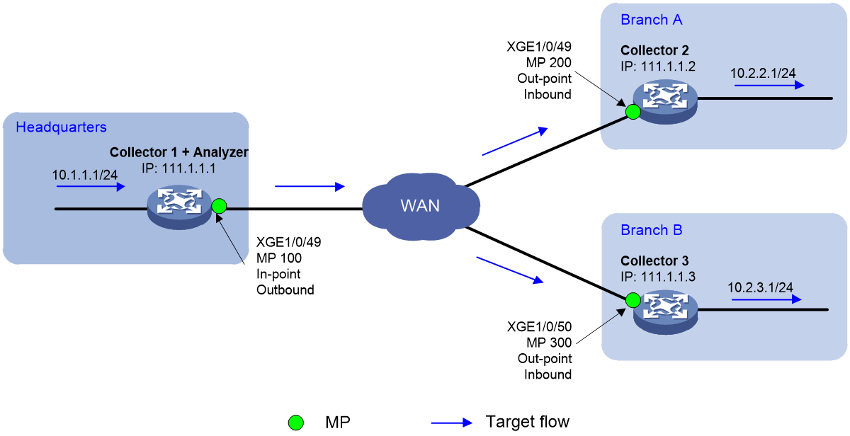
As shown in Figure 4, the headquarters connects to Branch A and Branch B through the WAN. The headquarters conducts live video tests with Branch A and Branch B at the same time and experiences lags and stutters in both tests. Configure iNQA to measure the packet loss rate of the video service flows over the WAN as follows:
· Enable the collector function and analyzer function on the edge device of the headquarters.
· Enable the collector function on the edge devices of Branch A and Branch B.
· Define the flows from the headquarters to Branch A and Branch B as forward flows, respectively.
· Set the packet loss upper threshold and lower threshold for the target flow to 6% and 4%, respectively. Alarms will be generated if the packet loss rate of the flow exceeds the upper threshold.
· Measure the packet loss rate from MP 100 to MP 200 and from MP 100 to MP 300.
Prerequisites
1. Assign 111.1.1.1, 111.1.1.2, and 111.1.1.3 to Collector 1 (the analyzer), Collector 2, and Collector 3, respectively. Make sure the Collector 1, Collector 2, and Collector 3 can reach each other. (Details not shown.)
2. Configure NTP or PTP on Collector 1, Collector 2, and Collector 3 for clock synchronization. (Details not shown.)
Procedure
1. Configure Collector 1 and the analyzer:
Configure Ten-GigabitEthernet 1/0/49 on Collector 1 as an ingress point and configure iNQA to measure the flows leaving this point.
#
inqa analyzer
analyzer id 111.1.1.1
instance 1
collector 111.1.1.1
collector 111.1.1.2
collector 111.1.1.3
loss-measure alarm upper-limit 6.000000 lower-limit 4.000000
measure enable
#
inqa collector
collector id 111.1.1.1
analyzer 111.1.1.1
flag loss-measure tos-bit 5
instance 1
flow forward source-ip 10.1.1.0 24 destination-ip 10.2.0.0 16
mp 100 in-point port-direction outbound
loss-measure enable continual
#
interface Ten-GigabitEthernet1/0/49
port link-mode bridge
inqa mp 100
2. Configure Collector 2 as follows:
Configure Ten-GigabitEthernet 1/0/49 on Collector 2 as an egress point and configure iNQA to measure the flows entering this point.
#
inqa collector
collector id 111.1.1.2
analyzer 111.1.1.1
flag loss-measure tos-bit 5
instance 1
flow forward source-ip 10.1.1.0 24 destination-ip 10.2.0.0 16
mp 200 out-point port-direction inbound
loss-measure enable continual
#
interface Ten-GigabitEthernet1/0/49
port link-mode bridge
inqa mp 200
3. Configure Collector 3 as follows:
Configure Ten-GigabitEthernet1/0/50 on Collector 3 as an egress point and configure iNQA to measure the flows entering this point.
#
inqa collector
collector id 111.1.1.3
analyzer 111.1.1.1
flag loss-measure tos-bit 5
instance 1
flow forward source-ip 10.1.1.0 24 destination-ip 10.2.0.0 16
mp 300 out-point port-direction inbound
loss-measure enable continual
#
interface Ten-GigabitEthernet1/0/50
port link-mode bridge
inqa mp 300
Verifying the configuration
1. Verify the measurement result on Collector 1 and the analyzer:
# Display the collector configuration.
<Collector1+Analyzer> display inqa collector
Collector ID : 111.1.1.1
Loss-measure flag : 5
Analyzer ID : 111.1.1.1
Analyzer UDP-port : 53312
VPN-instance-name : --
Current instance count : 1
# Display the configuration of collector instance 1.
<Collector1+Analyzer> display inqa collector instance 1
Instance ID : 1
Status : Enabled
Duration : --
Description : --
Analyzer ID : --
Analyzer UDP-port : --
VPN-instance-name : --
Interval : 10 sec
Flow configuration:
flow forward source-ip 10.1.1.0 24 destination-ip 10.2.0.0 16
MP configuration:
mp 100 in-point outbound, XGE1/0/49
# Display the analyzer configuration.
<Collector1+Analyzer> display inqa analyzer
Analyzer ID : 111.1.1.1
Protocol UDP-port : 53312
Current instance count : 1
<Collector1+Analyzer> display inqa analyzer instance 1
Instance ID : 1
Status : Enable
Description : --
Alarm upper-limit : 6.000000%
Alarm lower-limit : 4.000000%
Current AMS count : 0
Collectors : 111.1.1.1
111.1.1.2
111.1.1.3
2. Verify the measurement result on Collector 2:
# Display the collector configuration.
<Collector2> display inqa collector
Collector ID : 111.1.1.2
Loss-measure flag : 5
Analyzer ID : 111.1.1.1
Analyzer UDP-port : 53312
VPN-instance-name : --
Current instance count : 1
# Display the configuration of collector instance 1.
<Collector2> display inqa collector instance 1
Instance ID : 1
Status : Enabled
Duration : --
Description : --
Analyzer ID : --
Analyzer UDP-port : --
VPN-instance-name : --
Interval : 10 sec
Flow configuration:
flow forward source-ip 10.1.1.0 24 destination-ip 10.2.0.0 16
MP configuration:
mp 200 out-point inbound, XGE1/0/49
3. Verify the measurement result on Collector 3:
# Display the collector configuration.
<Collector3> display inqa collector
Collector ID : 111.1.1.3
Loss-measure flag : 5
Analyzer ID : 111.1.1.1
Analyzer UDP-port : 53312
VPN-instance-name : --
Current instance count : 1
# Display the configuration of collector instance 1.
<Collector3> display inqa collector instance 1
Instance ID : 1
Status : Enabled
Duration : --
Description : --
Analyzer ID : --
Analyzer UDP-port : --
VPN-instance-name : --
Interval : 10 sec
Flow configuration:
flow forward source-ip 10.1.1.0 24 destination-ip 10.2.0.0 16
MP configuration:
mp 300 out-point inbound, XGE1/0/50
4. Verify the measurement result on Collector 1 and the analyzer:
# Construct a packet loss test environment. Configure ACLs on the WAN devices so they can drop packets sourced from 10.1.1.0 and destined for 10.2.2.0 temporarily. (Details not shown.)
# Display iNQA end-to-end packet loss statistics of analyzer instance 1.
<Collector1+Analyzer> display inqa statistics loss instance 1
Latest packet loss statistics for forward flow:
Period LostPkts PktLoss% LostBytes ByteLoss%
160335018 0 0.000000% 0 0.000000%
160335017 0 0.000000% 0 0.000000%
160335016 2869 14.382394% 367232 14.382394%
160335015 6195 30.982746% 792960 30.982746%
160335014 0 0.000000% 0 0.000000%
160335013 0 0.000000% 0 0.000000%
160335012 0 0.000000% 0 0.000000%
160335011 0 0.000000% 0 0.000000%
160335010 0 0.000000% 0 0.000000%
160335009 0 0.000000% 0 0.000000%
160335008 0 0.000000% 0 0.000000%
160335007 0 0.000000% 0 0.000000%
Latest packet loss statistics for backward flow:
Period LostPkts PktLoss% LostBytes ByteLoss%
160335018 0 0.000000% 0 0.000000%
160335017 0 0.000000% 0 0.000000%
160335016 0 0.000000% 0 0.000000%
160335015 0 0.000000% 0 0.000000%
160335014 0 0.000000% 0 0.000000%
160335013 0 0.000000% 0 0.000000%
160335012 0 0.000000% 0 0.000000%
160335011 0 0.000000% 0 0.000000%
160335010 0 0.000000% 0 0.000000%
160335009 0 0.000000% 0 0.000000%
160335008 0 0.000000% 0 0.000000%
160335007 0 0.000000% 0 0.000000%
iNQA restrictions and guidelines
· iNQA is available for IPv4 unicast traffic but not available for IPv4 multicast traffic or IPv6 traffic.
· Do not configure iNQA in the VXLAN network.
· The iNQA measurement result might be inaccurate if the packet header is modified during the transmission, for example, insertion or removal of the VLAN tag.
· When a flow travels across different networks, the packet header might be modified, making the measurement for the packet different at different MPs. If the packets are encapsulated or decapsulated during the transmission over different networks, iNQA cannot identify the target flow at different MPs for measurement.
· iNQA uses ToS field bits 5 to 7 in the IPv4 packet header as the flag bit. The ToS field bit used as the flag bit varies by device model and network condition. The S5560X and S6520X switches support only ToS field bit 5 as the flag bit. To avoid inaccurate packet loss measurement, do not use bit 5 for DSCP purposes if the bit is used as the flag bit.
· To specify ToS field bit 6 or 7 as the flag bit, do not enable ECN, and vice versa.
· As a best practice, do not enable INT and iNQA on the same device.
· iNQA on an aggregate interface might function incorrectly after a new port joins the aggregation group and causes ACL resource shortage. To resolve the issue, you can reduce the number of member ports in the aggregate group. Or, you can delete unnecessary ACLs to release the ACL resources before adding a new port to the aggregate group.
· With iNQA enabled on a Layer 2 aggregate interface, do not execute the port s-mlag group command to assign the Layer 2 aggregate interface to an S-MLAG group.
Recommended devices for iNQA
|
Device model |
Collector |
Analyzer |
Recommended version |
|
S5560X |
Supported |
Supported |
F6510 or later |
|
S6520X |
Supported |
Supported |
F6510 or later |