- Table of Contents
- Related Documents
-
| Title | Size | Download |
|---|---|---|
| 01-IRF Configuration Examples | 506.71 KB |
General restrictions and guidelines
Feature compatibility and configuration restrictions
IRF physical interface requirements
Applicable hardware and software versions
Management IP address configuration restrictions and guidelines
ARP MAD configuration restrictions and guidelines
Configuring management IP addresses
Applicable hardware and software versions
Management IP address configuration restrictions and guidelines
BFD MAD configuration restrictions and guidelines
Configuring management IP addresses
Example: Setting up a LACP MAD-enabled two-chassis IRF fabric
Applicable hardware and software versions
Configuring the downlink services
Verifying the link backup function of multichassis aggregations
Verifying the link backup function of IRF connections
Example: Setting up an LACP MAD-enabled four-chassis IRF fabric
Applicable hardware and software versions
Verifying the link backup function of multichassis aggregations
Example: Upgrading a two-chassis IRF fabric to a four-chassis IRF fabric (BFD MAD)
Applicable hardware and software versions
Adding two chassis to a two-chassis IRF fabric
Merging two two-chassis IRF fabrics
Verifying the link backup function of multichassis aggregations
Introduction
This document provides examples for setting up IRF fabrics and configuring link aggregation and routing on the IRF fabrics.
Prerequisites
The configuration examples in this document were created and verified in a lab environment, and all the devices were started with the factory default configuration. When you are working on a live network, make sure you understand the potential impact of every command on your network.
This document assumes that you have basic knowledge of IRF.
General restrictions and guidelines
When you set up and configure an IRF fabric, follow the restrictions and guidelines in this section.
This section provides only the basic restrictions and guidelines that ensure a successful IRF deployment. For complete information, see IRF configuration guide for the switch.
Hardware requirements
The switch can form an IRF fabric only with switches of the same model.
Software requirements
All IRF member devices must run the same system software version.
Feature compatibility and configuration restrictions
To ensure a successful IRF setup, make sure the following requirements are met:
· Settings for the following features are the same across the candidate member devices:
|
Feature |
Command |
|
Maximum number of ECMP routes |
max-ecmp-num |
|
Port speed mode for the expansion interface modules |
port-speed-mode |
|
Multicast forwarding mode |
fabric multicast-forwarding mode |
· Port isolation is not configured on any candidate member devices.
· PTP is disabled on all candidate member devices.
IRF physical interface requirements
Use Table 1 to select ports for establishing IRF links and make sure the described requirements are met.
Table 1 IRF physical ports and use restrictions
|
Hardware |
Candidate IRF physical interfaces |
Restrictions |
|
S7800XP-G switch series S9600XP-G switch series |
QSFP28 ports |
You cannot use the 10G or 25G breakout Ethernet interfaces of a QSFP28 port as IRF physical interfaces. |
|
S5200-HI-G switch series S5200-EI-G switch series |
SFP+ ports |
N/A |
|
S5600-EI-G switch series |
10G fiber Ethernet ports |
N/A |
|
S5800XP-HI-G switch series |
10G/25G/40G/100G fiber Ethernet ports |
N/A |
|
S6600X-EI-G switch series S6600XP-EI-G switch series |
10G/40G/100G fiber Ethernet ports |
N/A |
|
S5200-30C-EI-G switch series S5200-54C-EI-G switch series |
10G fiber Ethernet ports |
N/A |
|
S5800XP-HI-G switch series |
10G/25G/40G/100G fiber Ethernet ports |
N/A |
|
S6850-G switch series S6805-G switch series S9850-G switch series |
QSFP28 ports |
You cannot use the 10G or 25G breakout Ethernet interfaces of a QSFP28 port as IRF physical interfaces. |
|
S5590-HI, S5590-EI, and S5500V3-HI switch series |
· SFP+ ports on the front panel · Ports on the rear expansion interface modules (if installed): ¡ SFP+ ports except for those on the LSWM2SP2PB or LSWM2SP4PB module ¡ SFP28 ports ¡ QSFP+ ports ¡ QSFP28 ports |
Make sure all IRF physical interfaces bound to an IRF port are operating at the same rate. IRF physical interfaces bound to an IRF port can come from the front panel, expansion interface modules, or both. Port speed requirements for IRF ports: · To use SFP+ ports as IRF physical interfaces, the ports must operate at 10 Gbps. · To use SFP28 ports as IRF physical interfaces, the ports must operate at 25 Gbps. · To use QSFP+ ports as IRF physical interfaces, the ports must operate at 40 Gbps. · To use QSFP28 ports as IRF physical interfaces, the ports must operate at 40 Gbps or 100 Gbps. |
|
S5560-EI-G switch series |
10G fiber Ethernet ports |
N/A |
|
S5590XP-HI-G switch series |
10G/25G/40G/100G fiber Ethernet ports |
N/A |
|
S6520X-EI-G switch series S6520XP-EI-G switch series |
10G/40G/100G fiber Ethernet ports |
N/A |
|
S5130S-EI-G switch series |
10G fiber Ethernet ports |
N/A |
Connecting IRF ports
When you connect two neighboring IRF members, connect the physical interfaces of IRF-port 1 on one member to the physical interfaces of IRF-port 2 on the other.
Example: Setting up a two-chassis IRF fabric with ARP MAD and management IP configured on the same management Ethernet port
|
|
IMPORTANT: This example is also applicable to a two-chassis IRF fabric running ND MAD, except that you must configure ND MAD differently. For more information about MAD configuration, see the virtual technologies configuration guide for the device. |
Network configuration
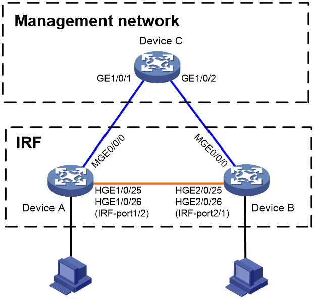
As shown in Figure 1, use Device A and Device B to set up a two-chassis IRF fabric.
Use management Ethernet port M-GigabitEthernet 0/0/0 to perform ARP MAD for IRF split detection and to provide device access for management purposes.
Configure management IP addresses for the IRF fabric and each member device on the management port to meet the following requirements:
· The administrator can use the same management IP address to access the IRF fabric before and after a master/subordinate switchover.
· The administrator can access each member device for failure recovery through their respective management IP addresses after the IRF fabric splits.
Applicable hardware and software versions
The following matrix shows the hardware and software versions to which this configuration example is applicable:
|
Hardware |
Software version |
|
S9850-G switch series |
Release 6010P03 and later |
|
S6850-G switch series S6805-G switch series |
Release 6010P03 and later |
|
S6530X switch series |
Release 8108P22 and later |
|
S5590-HI switch series |
Release 6010P03 and later |
|
S5590-EI switch series S5500V3-HI switch series |
Release 6010P03 and later |
|
S6520X-EI-G switch series S6520XP-EI-G switch series |
Release 7748 and later |
|
S5590XP-HI-G switch series |
Release 7748 and later |
|
S5560-EI-G switch series |
Release 7748 and later |
|
S5500-D-G switch series S5100-D-G switch series |
Release 6010P03 and later |
|
S5130S-HI-G switch series |
Release 6010P03 and later |
|
S5130S-EI-G switch series (except S5130S-30C-EI-G and S5130S-54C-EI-G switches) |
Release 6010P03 and later |
|
S5130S-30C-EI-G switch S5130S-54C-EI-G switch |
Release 7748 and later |
Restrictions and guidelines
Management IP address configuration restrictions and guidelines
When you configure management IP addresses, follow these restrictions and guidelines:
· To make sure you can access the IRF fabric at the same IP address after a master/subordinate switchover, use the ip address ip-address { mask-length | mask } command to configure a management IP address on the management port, in this example, on M-GigabitEthernet 0/0/0. You can use this address to access the IRF fabric as long as the fabric has not split. This address might be inaccessible for an IP conflict after the IRF fabric splits, because it exists on all member devices. In the context of IRF, this address is called a global management IP address.
· To access each member device for failure recovery after the IRF fabric splits, use the ip address ip-address { mask-length | mask } irf-member member-id command to configure a management IP address for each member device on the management port, in this example, on M-GigabitEthernet 0/0/0. In the context of IRF, this address is called a member-specific management IP address.
· Make sure the management IP addresses assigned to all IRF member devices on the same management Ethernet port belong to the same subnet. Make sure the management IP addresses assigned to an IRF member device on different management Ethernet ports belong to different subnets.
· You must manually make sure the management IP addresses configured on the subordinate devices will not cause IP address conflicts on the network. When the IRF fabric is running correctly, only the IP addresses of the management Ethernet ports on the master device take effect. The management IP addresses of the management Ethernet ports on the subordinate devices do not take effect. If a management IP address on a subordinate device conflicts with an IP address in the network, the system cannot detect the IP conflict, causing network issues after an IRF split.
|
|
NOTE: When the IRF fabric is integrated, you can access the IRF fabric by using either the global management IP address or the management IP address specific to the master device. As a best practice to prevent the management IP address from changing upon a master/subordinate switchover, use the global management IP address as long as the IRF fabric is integrated. |
ARP MAD configuration restrictions and guidelines
When you configure ARP MAD on a management Ethernet port, follow these restrictions and guidelines:
|
Category |
Restrictions and guidelines |
|
Management Ethernet ports for ARP MAD |
Connect a management Ethernet port on each member device to the common Ethernet ports on the intermediate device. |
|
ARP MAD VLAN |
On the intermediate device, create a VLAN for ARP MAD, and assign the ports used for ARP MAD to the VLAN. On the IRF fabric, you do not need to assign the management Ethernet ports to the VLAN. |
|
ARP MAD and feature configuration |
· Enable the IRF fabric to change its bridge MAC address as soon as the address owner leaves. · If the intermediate device is also an IRF fabric, assign the two IRF fabrics different domain IDs for correct split detection. |
Procedures
Setting up the IRF fabric
1. Configure Device A:
# Shut down the physical interfaces used for IRF connection. This example uses HundredGigE 1/0/25 and HundredGigE 1/0/26 for IRF connection.
<DeviceA> system-view
[DeviceA] interface range hundredgige 1/0/25 to hundredgige 1/0/26
[DeviceA-if-range] shutdown
[DeviceA-if-range] quit
# Bind HundredGigE 1/0/25 and HundredGigE 1/0/26 to IRF-port 1/2.
[DeviceA] irf-port 1/2
[DeviceA-irf-port1/2] port group interface hundredgige 1/0/25
[DeviceA-irf-port1/2] port group interface hundredgige 1/0/26
[DeviceA-irf-port1/2] quit
# Bring up the physical interfaces.
[DeviceA] interface range hundredgige 1/0/25 to hundredgige 1/0/26
[DeviceA-if-range] undo shutdown
[DeviceA-if-range] quit
# Save the running configuration to the next-startup configuration file.
[DeviceA] quit
<DeviceA> save
# Activate the IRF port configuration.
<DeviceA> system-view
[DeviceA] irf-port-configuration active
2. Configure Device B:
# Assign member ID 2 to Device B, and reboot the device to have the change take effect.
<DeviceB> system-view
[DeviceB] irf member 1 renumber 2
Renumbering the member ID may result in configuration change or loss. Continue? [Y/N]:y
[DeviceB] quit
<DeviceB> reboot
# Shut down the physical interfaces used for IRF connection. This example uses HundredGigE 2/0/25 and HundredGigE 2/0/26 for IRF connection.
<DeviceB> system-view
[DeviceB] interface range hundredgige 2/0/25 to hundredgige 2/0/26
[DeviceB-if-range] shutdown
[DeviceB-if-range] quit
# Bind HundredGigE 2/0/25 and HundredGigE 2/0/26 to IRF-port 2/1.
[DeviceB] irf-port 2/1
[DeviceB-irf-port2/1] port group interface hundredgige 2/0/25
[DeviceB-irf-port2/1] port group interface hundredgige 2/0/26
[DeviceB-irf-port2/1] quit
# Bring up the physical interfaces.
[DeviceB] interface range hundredgige 2/0/25 to hundredgige 2/0/26
[DeviceB-if-range] undo shutdown
[DeviceB-if-range] quit
# Save the running configuration to the next-startup configuration file.
[DeviceB] quit
<DeviceB> save
# Connect Device B to Device A, as shown in Figure 1.
# Activate the IRF port configuration.
<DeviceB> system-view
[DeviceB] irf-port-configuration active
Device A and Device B perform master election. The device that has failed master election automatically reboots to form an IRF fabric with the other device. A two-chassis IRF fabric is formed.
Configuring management IP addresses
# Assign IP address 192.168.1.1/24 to the IRF fabric on management Ethernet port M-GigabitEthernet 0/0/0.
<IRF> system-view
[IRF] interface m-gigabitethernet 0/0/0
[IRF-M-GigabitEthernet0/0/0] ip address 192.168.1.1 24
# On management Ethernet port M-GigabitEthernet 0/0/0, assign IP addresses 192.168.1.101/24 and 192.168.1.102/24 to IRF member device 1 (Device A) and IRF member device 2 (Device B), respectively. After the IRF fabric splits, the administrator can use IP addresses 192.168.1.101/24 and 192.168.1.102/24 to log in to Device A and Device B, respectively.
[IRF-M-GigabitEthernet0/0/0] ip address 192.168.1.101 24 irf-member 1
[IRF-M-GigabitEthernet0/0/0] ip address 192.168.1.102 24 irf-member 2
[IRF-M-GigabitEthernet0/0/0] quit
# Exclude management Ethernet port M-GigabitEthernet 0/0/0 from being shut down by MAD upon detection of multi-active collisions.
[IRF] mad exclude interface m-gigabitethernet 0/0/0
Configuring ARP MAD
1. Configure the IRF fabric:
# Configure the IRF fabric to change its bridge MAC address as soon as the address owner leaves.
[IRF] undo irf mac-address persistent
# Set the domain ID of the IRF fabric to 1.
[IRF] irf domain 1
# Enable ARP MAD on management Ethernet port M-GigabitEthernet 0/0/0.
[IRF] interface m-gigabitethernet 0/0/0
[IRF-M-GigabitEthernet0/0/0] mad arp enable
You need to assign a domain ID (range: 0-4294967295)
[Current domain ID is: 1]:
The assigned domain ID is: 1
[IRF-M-GigabitEthernet0/0/0] quit
# Save the running configuration to the next-startup configuration file.
[IRF] save
2. Configure Device C as the intermediate device:
# Create VLAN 100.
<DeviceC> system-view
[DeviceC] vlan 100
# Assign GigabitEthernet 1/0/1 and GigabitEthernet 1/0/2 to VLAN 100 for forwarding ARP MAD packets.
[DeviceC-vlan100] port gigabitethernet 1/0/1 to gigabitethernet 1/0/2
[DeviceC-vlan100] quit
Verifying the configuration
# Disconnect the IRF links between Device A and Device B. Verify that you can use 192.168.1.101 and 192.168.1.102 to log in to Device A and Device B, respectively. (Details not shown.)
# Execute the display mad verbose command on Device A and Device B to verify that MAD is correctly functioning, as follows:
· The Multi-active recovery state field displays Yes on one device and displays No on the other device.
· On each device, the IRF physical interfaces and management Ethernet port M-GigabitEthernet 0/0/0 are excluded from being shut down by MAD.
# Execute the display interface brief command on Device A and Device B to verify that the MAD shutdown action is performed correctly, as follows:
· On the device in Recovery state, all network interfaces have been shut down by MAD except the IRF physical interfaces and management Ethernet port M-GigabitEthernet 0/0/0.
· On the device not in Recovery state, no network interfaces are shut down by MAD.
Configuration files
· IRF fabric:
#
irf-port 1/2
port group interface HundredGigE1/0/25
port group interface HundredGigE1/0/26
#
irf-port 2/1
port group interface HundredGigE2/0/25
port group interface HundredGigE2/0/26
#
irf domain 1
undo irf mac-address persistent
#
interface M-GigabitEthernet0/0/0
ip address 192.168.1.1 255.255.255.0
ip address 192.168.1.101 255.255.255.0 irf-member 1
ip address 192.168.1.102 255.255.255.0 irf-member 2
mad arp enable
#
mad exclude interface M-GigabitEthernet0/0/0
#
· Device C:
#
vlan 100
#
GigabitEthernet 1/0/1
port access vlan 100
#
Gigabitethernet 1/0/2
port access vlan 100
#
Example: Setting up a two-chassis IRF fabric with BFD MAD and management IP configured on separate management Ethernet ports
|
|
IMPORTANT: This example is also applicable to a two-chassis IRF fabric running ARP MAD or ND MAD, except that you must configure ARP MAD and ND MAD differently. For more information about MAD configuration, see the virtual technologies configuration guide for the device. |
Network configuration
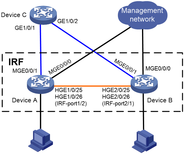
As shown in Figure 2, use Device A and Device B to set up a two-chassis IRF fabric.
Use management Ethernet port M-GigabitEthernet 0/0/0 on Device A and Device B for device management purposes. Configure management IP addresses for the IRF fabric and each member device on the management port to meet the following requirements:
· The administrator can use the same management IP address to access the IRF fabric before and after a master/subordinate switchover.
· The administrator can access each member device for failure recovery through their respective management IP addresses after the IRF fabric splits.
Use management Ethernet port M-GigabitEthernet 0/0/1 to perform BFD MAD for IRF split detection.
Applicable hardware and software versions
The following matrix shows the hardware and software versions to which this configuration example is applicable:
|
Hardware |
Software version |
|
S9850-G switch series |
Release 6010P03 and later |
|
S6850-G switch series S6805-G switch series |
Release 6010P03 and later |
|
S6530X switch series |
Release 8108P22 and later |
|
S5590-HI switch series |
Release 6010P03 and later |
|
S5590-EI switch series S5500V3-HI switch series |
Release 6010P03 and later |
|
S6520X-EI-G switch series S6520XP-EI-G switch series |
Release 7748 and later |
|
S5590XP-HI-G switch series |
Release 7748 and later |
|
S5560-EI-G switch series |
Release 7748 and later |
|
S5500-D-G switch series S5100-D-G switch series |
Not supported |
|
S5130S-HI-G switch series |
Not supported |
|
S5130S-EI-G switch series (except S5130S-30C-EI-G and S5130S-54C-EI-G switches) |
Not supported |
|
S5130S-30C-EI-G switch S5130S-54C-EI-G switch |
Release 7748 and later |
Restrictions and guidelines
Management IP address configuration restrictions and guidelines
When you configure management IP addresses, follow these restrictions and guidelines:
· To make sure you can access the IRF fabric at the same IP address after a master/subordinate switchover, use the ip address ip-address { mask-length | mask } command to configure a management IP address on the management port, in this example, on M-GigabitEthernet 0/0/0. You can use this address to access the IRF fabric as long as the fabric has not split. This address might be inaccessible for an IP conflict after the IRF fabric splits, because it exists on all member devices. In the context of IRF, this address is called a global management IP address.
· To access each member device for failure recovery after the IRF fabric splits, use the ip address ip-address { mask-length | mask } irf-member member-id command to configure a management IP address for each member device on the management port, in this example, on M-GigabitEthernet 0/0/0. In the context of IRF, this address is called a member-specific management IP address.
· Make sure the management IP addresses assigned to all IRF member devices on the same management Ethernet port belong to the same subnet. Make sure the management IP addresses assigned to an IRF member device on different management Ethernet ports belong to different subnets.
· You must manually make sure the management IP addresses configured on the subordinate devices will not cause IP address conflicts on the network. When the IRF fabric is running correctly, only the IP addresses of the management Ethernet ports on the master device take effect. The management IP addresses of the management Ethernet ports on the subordinate devices do not take effect. If a management IP address on a subordinate device conflicts with an IP address in the network, the system cannot detect the IP conflict, causing network issues after an IRF split.
|
|
NOTE: When the IRF fabric is integrated, you can access the IRF fabric by using either the global management IP address or the management IP address specific to the master device. As a best practice to prevent the management IP address from changing upon a master/subordinate switchover, use the global management IP address as long as the IRF fabric is integrated. |
BFD MAD configuration restrictions and guidelines
When you configure BFD MAD on a management Ethernet port, follow these restrictions and guidelines:
|
Category |
Restrictions and guidelines |
|
Management Ethernet ports for BFD MAD |
Connect a management Ethernet port on each IRF member device to the common Ethernet ports on the intermediate device. |
|
BFD MAD VLAN |
· On the intermediate device, create a VLAN for BFD MAD, and assign the ports used for BFD MAD to the VLAN. On the IRF fabric, you do not need to assign the management Ethernet ports to the VLAN. · Make sure the IRF fabrics on the network use different BFD MAD VLANs. · Make sure the BFD MAD VLAN on the intermediate device contains only ports on the BFD MAD links. |
|
MAD IP address |
· To avoid network issues, only use the mad ip address command to configure IP addresses on the BFD MAD-enabled management Ethernet port. Do not configure an IP address by using the ip address command or configure a VRRP virtual address on the BFD MAD-enabled management Ethernet port. · Make sure all the MAD IP addresses are on the same subnet. |
Procedures
Setting up the IRF fabric
1. Configure Device A:
# Shut down the physical interfaces used for IRF connection. This example uses HundredGigE 1/0/25 and HundredGigE 1/0/26 for IRF connection.
<DeviceA> system-view
[DeviceA] interface range hundredgige 1/0/25 to hundredgige 1/0/26
[DeviceA-if-range] shutdown
[DeviceA-if-range] quit
# Bind HundredGigE 1/0/25 and HundredGigE 1/0/26 to IRF-port 1/2.
[DeviceA] irf-port 1/2
[DeviceA-irf-port1/2] port group interface hundredgige 1/0/25
[DeviceA-irf-port1/2] port group interface hundredgige 1/0/26
[DeviceA-irf-port1/2] quit
# Bring up the physical interfaces.
[DeviceA] interface range hundredgige 1/0/25 to hundredgige 1/0/26
[DeviceA-if-range] undo shutdown
[DeviceA-if-range] quit
# Save the running configuration to the next-startup configuration file.
[DeviceA] quit
<DeviceA> save
# Activate the IRF port configuration.
<DeviceA> system-view
[DeviceA] irf-port-configuration active
2. Configure Device B:
# Assign member ID 2 to Device B, and reboot the device to have the change take effect.
<DeviceB> system-view
[DeviceB] irf member 1 renumber 2
Renumbering the member ID may result in configuration change or loss. Continue? [Y/N]:y
[DeviceB] quit
<DeviceB> reboot
# Shut down the physical interfaces used for IRF connection. This example uses HundredGigE 2/0/25 and HundredGigE 2/0/26 for IRF connection.
<DeviceB> system-view
[DeviceB] interface range hundredgige 2/0/25 to hundredgige 2/0/26
[DeviceB-if-range] shutdown
[DeviceB-if-range] quit
# Bind HundredGigE 2/0/25 and HundredGigE 2/0/26 to IRF-port 2/1.
[DeviceB] irf-port 2/1
[DeviceB-irf-port2/1] port group interface hundredgige 2/0/25
[DeviceB-irf-port2/1] port group interface hundredgige 2/0/26
[DeviceB-irf-port2/1] quit
# Bring up the physical interfaces.
[DeviceB] interface range hundredgige 2/0/25 to hundredgige 2/0/26
[DeviceB-if-range] undo shutdown
[DeviceB-if-range] quit
# Save the running configuration to the next-startup configuration file.
[DeviceB] quit
<DeviceB> save
# Connect Device B to Device A, as shown in Figure 2.
# Activate the IRF port configuration.
<DeviceB> system-view
[DeviceB] irf-port-configuration active
Device A and Device B perform master election. The device that has failed master election automatically reboots to form an IRF fabric with the other device.
Configuring management IP addresses
# Assign IP address 192.168.1.1/24 to the IRF fabric on management Ethernet port M-GigabitEthernet 0/0/0.
<IRF> system-view
[IRF] interface m-gigabitethernet 0/0/0
[IRF-M-GigabitEthernet0/0/0] ip address 192.168.1.1 24
# On management Ethernet port M-GigabitEthernet 0/0/0, assign IP addresses 192.168.1.101/24 and 192.168.1.102/24 to IRF member device 1 (Device A) and IRF member device 2 (Device B), respectively. After the IRF fabric splits, the administrator can use IP addresses 192.168.1.101/24 and 192.168.1.102/24 to log in to Device A and Device B, respectively.
[IRF-M-GigabitEthernet0/0/0] ip address 192.168.1.101 24 irf-member 1
[IRF-M-GigabitEthernet0/0/0] ip address 192.168.1.102 24 irf-member 2
[IRF-M-GigabitEthernet0/0/0] quit
# Exclude management Ethernet port M-GigabitEthernet 0/0/0 from being shut down by MAD upon detection of multi-active collisions.
[IRF] mad exclude interface m-gigabitethernet 0/0/0
Configuring BFD MAD
1. Configure the IRF fabric:
# Assign a MAD IP address to each IRF member device on management Ethernet port M-GigabitEthernet 0/0/1.
[IRF] interface m-gigabitethernet 0/0/1
[IRF-M-GigabitEthernet0/0/1] mad ip address 192.168.2.1 24 member 1
[IRF-M-GigabitEthernet0/0/1] mad ip address 192.168.2.2 24 member 2
# Enable BFD MAD on management Ethernet port M-GigabitEthernet 0/0/1.
[IRF-M-GigabitEthernet0/0/1] mad bfd enable
[IRF-M-GigabitEthernet0/0/1] quit
# Save the running configuration to the next-startup configuration file.
[IRF] save
2. Configure Device C as the intermediate device:
# Create VLAN 100.
<DeviceC> system-view
[DeviceC] vlan 100
# Assign GigabitEthernet 1/0/1 and GigabitEthernet 1/0/2 to VLAN 100 for forwarding BFD MAD packets.
[DeviceC-vlan100] port gigabitethernet 1/0/1 to gigabitethernet 1/0/2
[DeviceC-vlan100] quit
Verifying the configuration
# Disconnect the IRF links between Device A and Device B. Verify that you can use 192.168.1.101 and 192.168.1.102 to log in to Device A and Device B, respectively. (Details not shown.)
# Execute the display mad verbose command on Device A and Device B to verify that MAD is correctly functioning, as follows:
· The Multi-active recovery state field displays Yes on one device and displays No on the other device.
· On each device, the following network interfaces are excluded from being shut down by MAD:
¡ The IRF physical interfaces.
¡ Management Ethernet ports M-GigabitEthernet 0/0/0 and M-GigabitEthernet 0/0/1.
# Execute the display interface brief command on Device A and Device B to verify that the MAD shutdown action is performed correctly, as follows:
· On the device in Recovery state, all network interfaces have been shut down by MAD except the IRF physical interfaces and management Ethernet ports M-GigabitEthernet 0/0/0 and M-GigabitEthernet 0/0/1.
· On the device not in Recovery state, no network interfaces are shut down by MAD.
Configuration files
· IRF fabric:
#
irf-port 1/2
port group interface HundredGigE1/0/25
port group interface HundredGigE1/0/26
#
irf-port 2/1
port group interface HundredGigE2/0/25
port group interface HundredGigE2/0/26
#
interface M-GigabitEthernet0/0/0
ip address 192.168.1.1 255.255.255.0
ip address 192.168.1.101 255.255.255.0 irf-member 1
ip address 192.168.1.102 255.255.255.0 irf-member 2
#
interface M-GigabitEthernet0/0/1
mad bfd enable
mad ip address 192.168.2.1 255.255.255.0 member 1
mad ip address 192.168.2.2 255.255.255.0 member 2
#
mad exclude interface M-GigabitEthernet0/0/0
#
· Device C:
#
vlan 100
#
GigabitEthernet 1/0/1
port access vlan 100
#
Gigabitethernet 1/0/2
port access vlan 100
#
Example: Setting up a LACP MAD-enabled two-chassis IRF fabric
Network configuration
As shown in Figure 3:
· Set up a two-chassis IRF fabric at the core layer of the network.
· Use multichassis link aggregations to connect the IRF fabric to the access switches and the upstream egress routers.
· Use LACP MAD to detect IRF split.
· Run OSPF between the IRF fabric and the egress routers.
Figure 3 LACP MAD-enabled two-chassis IRF fabric
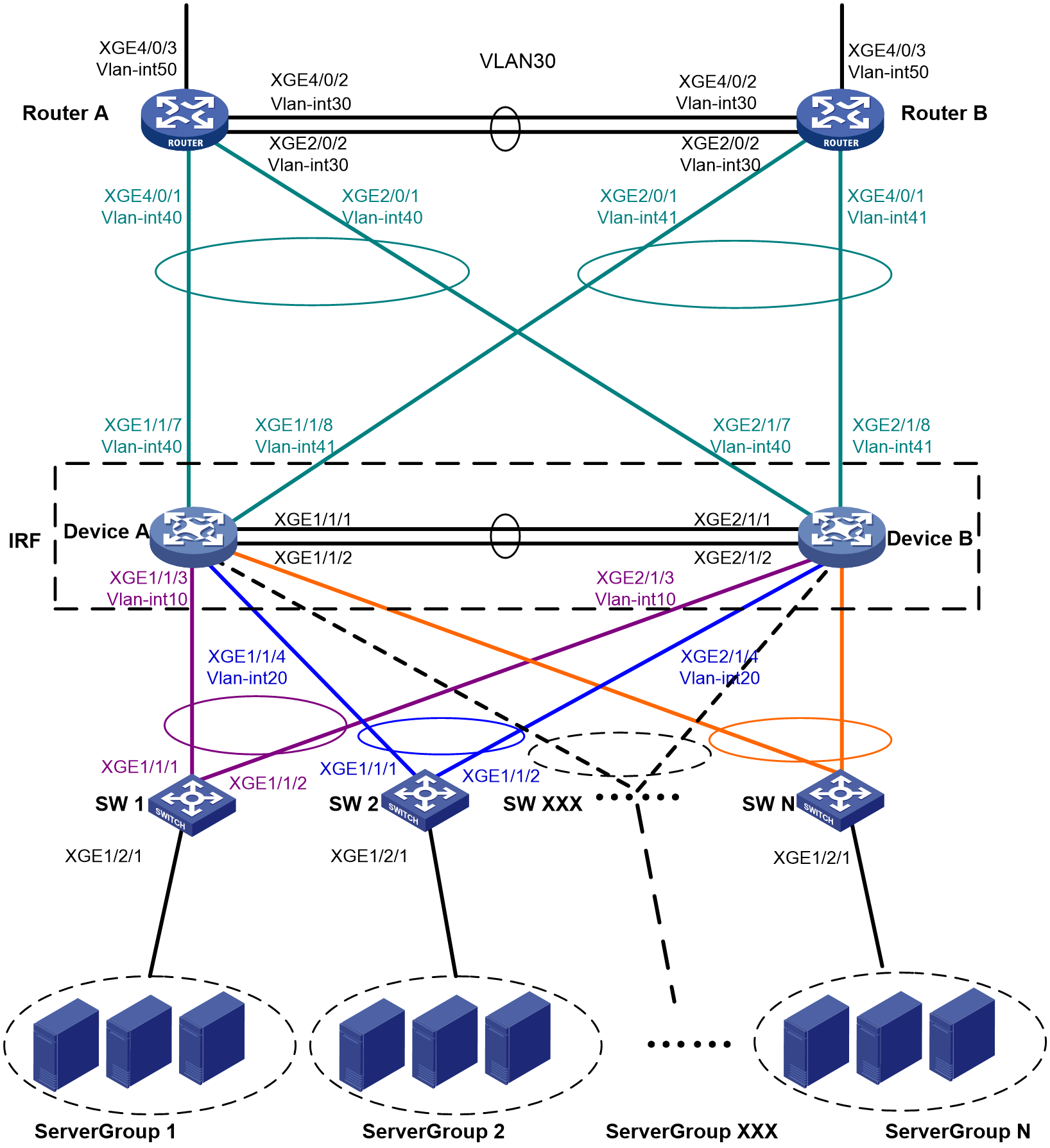
Table 2 VLAN and IP address assignment
|
Device |
VLAN interface |
IP address |
|
Router A |
VLAN-interface 30 |
172.24.2.2/24 |
|
Router A |
VLAN-interface 40 |
172.24.40.2/24 |
|
Router A |
VLAN-interface 50 |
172.24.1.2/24 |
|
Router B |
VLAN-interface 30 |
172.24.2.3/24 |
|
Router B |
VLAN-interface 41 |
172.24.41.3/24 |
|
Router B |
VLAN-interface 50 |
172.24.4.3/24 |
|
IRF fabric |
VLAN-interface 10 |
172.24.10.254/24 |
|
IRF fabric |
VLAN-interface 20 |
172.24.20.254/24 |
|
IRF fabric |
VLAN-interface 40 |
172.24.40.254/24 |
|
IRF fabric |
VLAN-interface 41 |
172.24.41.254/24 |
Analysis
For LACP MAD to run correctly, ensure that the intermediate device supports extended LACPDUs for LACP MAD.
To avoid single points of failure, use multichassis link aggregations to connect the IRF fabric to the downstream and upstream devices.
You do not need to run LACP MAD on all link aggregations. You can detect IRF split effectively by running LACP MAD on one dynamic link aggregation.
Applicable hardware and software versions
The following matrix shows the hardware and software versions to which this configuration example is applicable:
|
Hardware |
Software version |
|
S9850-G switch series |
Release 6010P03 and later |
|
S6850-G switch series S6805-G switch series |
Release 6010P03 and later |
|
S6530X switch series |
Release 8108P22 and later |
|
S5590-HI switch series |
Release 6010P03 and later |
|
S5590-EI switch series S5500V3-HI switch series |
Release 6010P03 and later |
|
S6520X-EI-G switch series S6520XP-EI-G switch series |
Release 7748 and later |
|
S5590XP-HI-G switch series |
Release 7748 and later |
|
S5560-EI-G switch series |
Release 7748 and later |
|
S5500-D-G switch series S5100-D-G switch series |
Release 6010P03 and later |
|
S5130S-HI-G switch series |
Release 6010P03 and later |
|
S5130S-EI-G switch series (except S5130S-30C-EI-G and S5130S-54C-EI-G switches) |
Release 6010P03 and later |
|
S5130S-30C-EI-G switch S5130S-54C-EI-G switch |
Release 7748 and later |
Restrictions and guidelines
When you configure LACP MAD on a link aggregation, follow these restrictions and guidelines:
· The link aggregation must use dynamic aggregation mode.
· The link aggregation must have a minimum of one member link from each member chassis.
· If the intermediate device is also an IRF fabric, you must assign the two IRF fabrics different domain IDs for correct split detection.
Procedures
Setting up the IRF fabric
1. Configure Device A:
# Shut down Ten-GigabitEthernet 1/1/1 and Ten-GigabitEthernet 1/1/2.
<DeviceA> system-view
[DeviceA] interface range ten-gigabitethernet 1/1/1 to ten-gigabitethernet 1/1/2
[DeviceA-if-range] shutdown
[DeviceA-if-range] quit
# Bind Ten-GigabitEthernet 1/1/1 and Ten-GigabitEthernet 1/1/2 to IRF-port 1/2.
[DeviceA] irf-port 1/2
[DeviceA-irf-port1/2] port group interface ten-gigabitethernet 1/1/1
[DeviceA-irf-port1/2] port group interface ten-gigabitethernet 1/1/2
[DeviceA-irf-port1/2] quit
# Bring up the IRF physical interfaces and save the running configuration.
[DeviceA] interface range ten-gigabitethernet 1/1/1 to ten-gigabitethernet 1/1/2
[DeviceA-if-range] undo shutdown
[DeviceA-if-range] quit
[DeviceA] save
# Activate the IRF port configuration.
[DeviceA] irf-port-configuration active
2. Configure Device B:
# Assign member ID 2 to Device B and reboot the device for the member ID to take effect.
<DeviceB> system-view
[DeviceB] irf member 1 renumber 2
Renumbering the member ID may result in configuration change or loss. Continue?[
Y/N]:y
[DeviceB] quit
<DeviceB> reboot
# Shut down Ten-GigabitEthernet 2/1/1 and Ten-GigabitEthernet 2/1/2.
<DeviceB> system-view
[DeviceB] interface range ten-gigabitethernet 2/1/1 to ten-gigabitethernet 2/1/2
[DeviceB-if-range] shutdown
[DeviceB-if-range] quit
# Bind Ten-GigabitEthernet 2/1/1 and Ten-GigabitEthernet 2/1/2 to IRF-port 2/1.
[DeviceB] irf-port 2/1
[DeviceB-irf-port2/1] port group interface ten-gigabitethernet 2/1/1
[DeviceB-irf-port2/1] port group interface ten-gigabitethernet 2/1/2
[DeviceB-irf-port2/1] quit
# Bring up the IRF physical interfaces and save the running configuration.
[DeviceB] interface range ten-gigabitethernet 2/1/1 to ten-gigabitethernet 2/1/2
[DeviceB-if-range] undo shutdown
[DeviceB-if-range] quit
[DeviceB] save
# Connect IRF-port 1/2 on Device A to IRF-port 2/1 on Device B, as shown in Figure 3.
# Activate the IRF port configuration.
[DeviceB] irf-port-configuration active
Configuring LACP MAD
After the IRF fabric is formed, the master's system name becomes the fabric's system name (Device A in this example). You can access the fabric by connecting to any of its member device and configure the fabric as you do on a standalone device.
# Create a Layer 2 dynamic aggregate interface Bridge-Aggregation 1. Enable LACP MAD on the aggregate interface.
<DeviceA> system-view
[DeviceA] interface bridge-aggregation 1
[DeviceA-Bridge-Aggregation1] link-aggregation mode dynamic
[DeviceA-Bridge-Aggregation1] mad enable
You need to assign a domain ID (range: 0-4294967295)
[Current domain is: 0]:
The assigned domain ID is: 0
[DeviceA-Bridge-Aggregation1] quit
# Assign the downlink ports that connect to SW 1 to the aggregation group of Bridge-Aggregation 1.
[DeviceA] interface ten-gigabitethernet 1/1/3
[DeviceA-Ten-GigabitEthernet1/1/3] port link-aggregation group 1
[DeviceA-Ten-GigabitEthernet1/1/3] quit
[DeviceA] interface ten-gigabitethernet 2/1/3
[DeviceA-Ten-GigabitEthernet2/1/3] port link-aggregation group 1
[DeviceA-Ten-GigabitEthernet2/1/3] quit
Configuring the downlink services
Configuring the IRF fabric
# Create Bridge-Aggregation 2.
[DeviceA] interface bridge-aggregation 2
[DeviceA-Bridge-Aggregation2] quit
# Assign the downlink ports that connect to SW 2 to the aggregation group.
[DeviceA] interface ten-gigabitethernet 1/1/4
[DeviceA-Ten-GigabitEthernet1/1/4] port link-aggregation group 2
[DeviceA-Ten-GigabitEthernet1/1/4] quit
[DeviceA] interface ten-gigabitethernet 2/1/4
[DeviceA-Ten-GigabitEthernet2/1/4] port link-aggregation group 2
[DeviceA-Ten-GigabitEthernet2/1/4] quit
# Create VLAN 10, assign an IP address to VLAN-interface 10 for connectivity to SW 1, and assign Bridge-Aggregation 1 to VLAN 10.
[DeviceA] vlan 10
[DeviceA-vlan10] quit
[DeviceA] interface vlan-interface 10
[DeviceA-Vlan-interface10] ip address 172.24.10.254 24
[DeviceA-Vlan-interface10] quit
[DeviceA] interface bridge-aggregation 1
[DeviceA-Bridge-Aggregation1] port link-type trunk
[DeviceA-Bridge-Aggregation1] undo port trunk permit vlan 1
[DeviceA-Bridge-Aggregation1] port trunk permit vlan 10
[DeviceA-Bridge-Aggregation1] quit
# Create VLAN 20, assign an IP address to VLAN-interface 20 for connectivity to SW 2, and assign Bridge-Aggregation 2 to VLAN 20.
[DeviceA] vlan 20
[DeviceA-vlan20] quit
[DeviceA] interface vlan-interface 20
[DeviceA-Vlan-interface20] ip address 172.24.20.254 24
[DeviceA-Vlan-interface20] quit
[DeviceA] interface bridge-aggregation 2
[DeviceA-Bridge-Aggregation2] port link-type trunk
[DeviceA-Bridge-Aggregation2] undo port trunk permit vlan 1
[DeviceA-Bridge-Aggregation2] port trunk permit vlan 20
[DeviceA-Bridge-Aggregation2] quit
Configuring SW 1
1. Configure a link aggregation:
# Create Bridge-Aggregation 1 and enable the dynamic aggregation mode. You must enable the dynamic aggregation mode because this link aggregation will be used for LACP MAD.
<SW1> system-view
[SW1] interface bridge-aggregation 1
[SW1-Bridge-Aggregation1] link-aggregation mode dynamic
[SW1-Bridge-Aggregation1] quit
# Assign the uplink ports that connect to the IRF fabric to Bridge-Aggregation 1.
[SW1] interface ten-gigabitethernet 1/1/1
[SW1-Ten-GigabitEthernet1/1/1] port link-aggregation group 1
[SW1-Ten-GigabitEthernet1/1/1] quit
[SW1] interface ten-gigabitethernet 1/1/2
[SW1-Ten-GigabitEthernet1/1/2] port link-aggregation group 1
[SW1-Ten-GigabitEthernet1/1/2] quit
2. Configure VLANs, ports, and IP addresses:
# Create all VLANs.
[SW1] vlan all
# Configure VLAN settings on the uplink aggregate interface that connects to the IRF fabric.
[SW1] interface bridge-aggregation 1
[SW1-Bridge-Aggregation1] port link-type trunk
[SW1-Bridge-Aggregation1] undo port trunk permit vlan 1
[SW1-Bridge-Aggregation1] port trunk permit vlan 10
[SW1-Bridge-Aggregation1] quit
# Configure VLAN settings on the port that connects to Server Group 1.
[SW1] interface ten-gigabitethernet 1/2/1
[SW1-Ten-GigabitEthernet1/2/1] port link-type trunk
[SW1-Ten-GigabitEthernet1/2/1] port trunk permit vlan all
[SW1-Ten-GigabitEthernet1/2/1] undo port trunk permit vlan 1
[SW1-Ten-GigabitEthernet1/2/1] quit
Configuring SW 2
1. Configure a link aggregation:
# Create Bridge-Aggregation 1.
<SW2>system-view
[SW2] interface bridge-aggregation 1
[SW2-Bridge-Aggregation1] quit
# Assign the uplink ports that connect to the IRF fabric to Bridge-Aggregation 1.
[SW2] interface ten-gigabitethernet 1/1/1
[SW2-Ten-GigabitEthernet1/1/1] port link-aggregation group 1
[SW2-Ten-GigabitEthernet1/1/1] quit
[SW2] interface ten-gigabitethernet 1/1/2
[SW2-Ten-GigabitEthernet1/1/2] port link-aggregation group 1
[SW2-Ten-GigabitEthernet1/1/2] quit
2. Configure VLANs, ports, and IP addresses:
# Create all VLANs.
[SW2] vlan all
# Configure VLAN settings on the uplink aggregate interface that connects to the IRF fabric.
[SW2] interface bridge-aggregation 1
[SW2-Bridge-Aggregation1] port link-type trunk
[SW2-Bridge-Aggregation1] undo port trunk permit vlan 1
[SW2-Bridge-Aggregation1] port trunk permit vlan 20
[SW2-Bridge-Aggregation1] quit
# Configure VLAN settings on the port that connects to Server Group 2.
[SW2] interface ten-gigabitethernet 1/2/1
[SW2-Ten-GigabitEthernet1/2/1] port link-type trunk
[SW2-Ten-GigabitEthernet1/2/1] port trunk permit vlan all
[SW2-Ten-GigabitEthernet1/2/1] undo port trunk permit vlan 1
[SW2-Ten-GigabitEthernet1/2/1] quit
Configuring uplink services
Configuring the IRF fabric
1. Configure connectivity to Router A:
# Create Bridge-Aggregation 1023. Assign the uplink ports that connect to Router A to Bridge-Aggregation 1023.
[DeviceA] interface bridge-aggregation 1023
[DeviceA-Bridge-Aggregation1023] quit
[DeviceA] interface ten-gigabitethernet 1/1/7
[DeviceA-Ten-GigabitEthernet1/1/7] port link-aggregation group 1023
[DeviceA-Ten-GigabitEthernet1/1/7] quit
[DeviceA] interface ten-gigabitethernet 2/1/7
[DeviceA-Ten-GigabitEthernet2/1/7] port link-aggregation group 1023
[DeviceA-Ten-GigabitEthernet2/1/7] quit
# Create VLAN 40, assign an IP address to VLAN-interface 40 for connectivity to Router A, and assign Bridge-Aggregation 1023 to VLAN 40.
[DeviceA] vlan 40
[DeviceA-vlan40] quit
[DeviceA] interface vlan-interface 40
[DeviceA-Vlan-interface40] ip address 172.24.40.254 24
[DeviceA-Vlan-interface40] quit
[DeviceA] interface bridge-aggregation 1023
[DeviceA-Bridge-Aggregation1023] port access vlan 40
[DeviceA-Bridge-Aggregation1023] quit
2. Configure connectivity to Router B:
# Create Bridge-Aggregation 1024. Assign the uplink ports that connect to Router B to Bridge-Aggregation 1024.
[DeviceA] interface bridge-aggregation 1024
[DeviceA-Bridge-Aggregation1024] quit
[DeviceA] interface ten-gigabitethernet 1/1/8
[DeviceA-Ten-GigabitEthernet1/1/8] port link-aggregation group 1024
[DeviceA-Ten-GigabitEthernet1/1/8] quit
[DeviceA] interface ten-gigabitethernet 2/1/8
[DeviceA-Ten-GigabitEthernet2/1/8] port link-aggregation group 1024
[DeviceA-Ten-GigabitEthernet2/1/8] quit
# Create VLAN 41, assign an IP address to VLAN-interface 41 for connectivity to Router B, and assign Bridge-Aggregation 1024 to VLAN 41.
[DeviceA] vlan 41
[DeviceA-vlan41] quit
[DeviceA] interface vlan-interface 41
[DeviceA-Vlan-interface41] ip address 172.24.41.254 24
[DeviceA-Vlan-interface41] quit
[DeviceA] interface bridge-aggregation 1024
[DeviceA-Bridge-Aggregation1024] port access vlan 41
[DeviceA-Bridge-Aggregation1024] quit
3. Configure OSPF between the IRF fabric and the egress routers.
[DeviceA] ospf
[DeviceA-ospf-1] import-route direct
[DeviceA-ospf-1] area 0
[DeviceA-ospf-1-area-0.0.0.0] network 172.24.40.0 0.0.0.255
[DeviceA-ospf-1-area-0.0.0.0] network 172.24.41.0 0.0.0.255
[DeviceA-ospf-1-area-0.0.0.0] quit
[DeviceA-ospf-1] quit
Configuring Router A
In this example, the egress router configuration only includes the connection to the IRF fabric.
1. Configure link aggregations:
# Create Bridge-Aggregation 1. Assign the downlink ports that connect to the IRF fabric to Bridge-Aggregation 1.
<RouterA> system-view
[RouterA] interface bridge-aggregation 1
[RouterA-Bridge-Aggregation1] quit
[RouterA] interface ten-gigabitethernet 4/0/1
[RouterA-Ten-GigabitEthernet4/0/1] port link-mode bridge
[RouterA-Ten-GigabitEthernet4/0/1] port link-aggregation group 1
[RouterA-Ten-GigabitEthernet4/0/1] quit
[RouterA] interface ten-gigabitethernet 2/0/1
[RouterA-Ten-GigabitEthernet2/0/1] port link-mode bridge
[RouterA-Ten-GigabitEthernet2/0/1] port link-aggregation group 1
[RouterA-Ten-GigabitEthernet2/0/1] quit
# Create Bridge-Aggregation 2. Assign the ports that connect to Router B to Bridge-Aggregation 2.
[RouterA] interface bridge-aggregation 2
[RouterA-Bridge-Aggregation2] quit
[RouterA] interface ten-gigabitethernet 4/0/2
[RouterA-Ten-GigabitEthernet4/0/2] port link-mode bridge
[RouterA-Ten-GigabitEthernet4/0/2] port link-aggregation group 2
[RouterA-Ten-GigabitEthernet4/0/2] quit
[RouterA] interface ten-gigabitethernet 2/0/2
[RouterA-Ten-GigabitEthernet2/0/2] port link-mode bridge
[RouterA-Ten-GigabitEthernet2/0/2] port link-aggregation group 2
[RouterA-Ten-GigabitEthernet2/0/2] quit
2. Configure VLANs, ports, and IP addresses:
# Create VLAN 40, assign an IP address to VLAN-interface 40, and assign Bridge-Aggregation 1 to VLAN 40.
[RouterA] vlan 40
[RouterA-vlan40] quit
[RouterA] interface vlan-interface 40
[RouterA-vlan-interface40] ip address 172.24.40.2 24
[RouterA-vlan-interface40] quit
[RouterA] interface bridge-aggregation 1
[RouterA-Bridge-Aggregation1] port access vlan 40
[RouterA-Bridge-Aggregation1] quit
# Create VLAN 30, assign an IP address to VLAN-interface 30, and assign Bridge-Aggregation 2 to VLAN 30.
[RouterA] vlan 30
[RouterA-vlan30] quit
[RouterA] interface vlan-interface 30
[RouterA-vlan-interface30] ip address 172.24.2.2 24
[RouterA-vlan-interface30] quit
[RouterA] interface bridge-aggregation 2
[RouterA-Bridge-Aggregation2] port link-type access
[RouterA-Bridge-Aggregation2] port access vlan 30
[RouterA-Bridge-Aggregation2] quit
# Create VLAN 50, assign an IP address to VLAN-interface 50, and assign Ten-GigabitEthernet 4/0/3 to VLAN 50.
[RouterA] vlan 50
[RouterA-vlan50] quit
[RouterA] interface vlan-interface 50
[RouterA-vlan-interface50] ip address 172.24.1.2 24
[RouterA-vlan-interface50] quit
[RouterA] interface ten-gigabitethernet 4/0/3
[RouterA-Ten-GigabitEthernet4/0/3] port link-mode bridge
[RouterA-Ten-GigabitEthernet4/0/3] port access vlan 50
[RouterA-Ten-GigabitEthernet4/0/3] quit
3. Configure OSPF between Router A and the IRF fabric.
[RouterA] ospf
[RouterA-ospf-1] import-route direct
[RouterA-ospf-1] area 0
[RouterA-ospf-1-area-0.0.0.0] network 172.24.40.0 0.0.0.255
[RouterA-ospf-1-area-0.0.0.0] network 172.24.2.0 0.0.0.255
[RouterA-ospf-1-area-0.0.0.0] quit
[RouterA-ospf-1] quit
Configuring Router B
In this example, the egress router configuration only includes the connection to the IRF fabric.
1. Configure link aggregations:
# Create Bridge-Aggregation 1. Assign the downlink ports that connect to the IRF fabric to Bridge-Aggregation 1.
<RouterB> system-view
[RouterB] interface bridge-aggregation 1
[RouterB-Bridge-Aggregation1] quit
[RouterB] interface ten-gigabitethernet 4/0/1
[RouterB-Ten-GigabitEthernet4/0/1] port link-mode bridge
[RouterB-Ten-GigabitEthernet4/0/1] port link-aggregation group 1
[RouterB-Ten-GigabitEthernet4/0/1] quit
[RouterB] interface ten-gigabitethernet 2/0/1
[RouterB-Ten-GigabitEthernet2/0/1] port link-mode bridge
[RouterB-Ten-GigabitEthernet2/0/1] port link-aggregation group 1
[RouterB-Ten-GigabitEthernet2/0/1] quit
# Create Bridge-Aggregation 2. Assign the ports that connect to Router A to Bridge-Aggregation 2.
[RouterB] interface bridge-aggregation 2
[RouterB-Bridge-Aggregation2] quit
[RouterB] interface ten-gigabitethernet 4/0/2
[RouterB-Ten-GigabitEthernet4/0/2] port link-mode bridge
[RouterB-Ten-GigabitEthernet4/0/2] port link-aggregation group 2
[RouterB-Ten-GigabitEthernet4/0/2] quit
[RouterB] interface ten-gigabitethernet 2/0/2
[RouterB-Ten-GigabitEthernet2/0/2] port link-mode bridge
[RouterB-Ten-GigabitEthernet2/0/2] port link-aggregation group 2
[RouterB-Ten-GigabitEthernet2/0/2] quit
2. Configure VLANs, ports, and IP addresses:
# Create VLAN 41, assign an IP address to VLAN-interface 41, and assign Bridge-Aggregation 1 to VLAN 41.
[RouterB] vlan 41
[RouterB-vlan41] quit
[RouterB] interface vlan-interface 41
[RouterB-vlan-interface41] ip address 172.24.41.3 24
[RouterB-vlan-interface41] quit
[RouterB] interface bridge-aggregation 1
[RouterB-Bridge-Aggregation1] port access vlan 41
[RouterB-Bridge-Aggregation1] quit
# Create VLAN 30, assign an IP address to VLAN-interface 30, and assign Bridge-Aggregation 2 to VLAN 30.
[RouterB] vlan 30
[RouterB-vlan30] quit
[RouterB] interface vlan-interface 30
[RouterB-vlan-interface30] ip address 172.24.2.3 24
[RouterB-vlan-interface30] quit
[RouterB] interface bridge-aggregation 2
[RouterB-Bridge-Aggregation2] port link-type access
[RouterB-Bridge-Aggregation2] port access vlan 30
[RouterB-Bridge-Aggregation2] quit
# Create VLAN 50, assign an IP address to VLAN-interface 50, and assign Ten-GigabitEthernet 4/0/3 to VLAN 50.
[RouterB] vlan 50
[RouterB-vlan50] quit
[RouterB] interface vlan-interface 50
[RouterB-vlan-interface50] ip address 172.24.4.3 24
[RouterB-vlan-interface50] quit
[RouterB] interface ten-gigabitethernet 4/0/3
[RouterB-Ten-GigabitEthernet4/0/3] port link-mode bridge
[RouterB-Ten-GigabitEthernet4/0/3] port access vlan 50
[RouterB-Ten-GigabitEthernet4/0/3] quit
3. Configure OSPF between Router B and the IRF fabric.
[RouterB] ospf
[RouterB-ospf-1] import-route direct
[RouterB-ospf-1] area 0
[RouterB-ospf-1-area-0.0.0.0] network 172.24.41.0 0.0.0.255
[RouterB-ospf-1-area-0.0.0.0] network 172.24.2.0 0.0.0.255
[RouterB-ospf-1-area-0.0.0.0] quit
[RouterB-ospf-1] quit
Verifying the configuration
Verify the IRF function, multichassis link aggregation configuration, and the IRF link redundancy backup function.
Verifying the IRF setup
# Execute the display irf command in any view.
[DeviceA] display irf
MemberID Role Priority CPU-Mac Description
*+1 Master 1 00e0-fc0f-8c02 ---
2 Standby 1 00e0-fc0f-8c03 ---
--------------------------------------------------
* indicates the device is the master.
+ indicates the device through which the user logs in.
The Bridge MAC of the IRF is: 3822-d60f-2800
Auto upgrade : yes
Mac persistent : always
Domain ID : 0
IRF mode : normal
The command output shows that the member chassis have formed an IRF fabric.
Verifying the link backup function of multichassis aggregations
# Shut down Ten-GigabitEthernet 1/1/8, the port connected to the egress router.
[DeviceA] interface ten-gigabitethernet 1/1/8
[DeviceA-Ten-GigabitEthernet1/1/8] shutdown
# Ping an IP address on the public network from a PC in Server Group 1.
C:\Users>ping 202.108.22.5 -t
Pinging 202.108.22.5 with 32 bytes of data:
Reply from 202.108.22.5: bytes=32 time=1ms TTL=122
Reply from 202.108.22.5: bytes=32 time=13ms TTL=122
Reply from 202.108.22.5: bytes=32 time<1ms TTL=122
Request timed out.
Request timed out.
Request timed out.
Reply from 202.108.22.5: bytes=32 time<1ms TTL=122
Reply from 202.108.22.5: bytes=32 time<1ms TTL=122
Reply from 202.108.22.5: bytes=32 time<1ms TTL=122
The output shows that the address can be pinged after transient traffic disruption.
# Bring up Ten-GigabitEthernet 1/1/8 and shut down Ten-GigabitEthernet 2/1/8.
[DeviceA-Ten-GigabitEthernet1/1/8] undo shutdown
[DeviceA-Ten-GigabitEthernet1/1/8] quit
[DeviceA] interface ten-gigabitethernet 2/1/8
[DeviceA-Ten-GigabitEthernet2/1/8] shutdown
# Ping the IP address on the public network from the PC.
C:\Users>ping 202.108.22.5 -t
Pinging 202.108.22.5 with 32 bytes of data:
Reply from 202.108.22.5: bytes=32 time=1ms TTL=122
Reply from 202.108.22.5: bytes=32 time=13ms TTL=122
Reply from 202.108.22.5: bytes=32 time<1ms TTL=122
Request timed out.
Request timed out.
Request timed out.
Reply from 202.108.22.5: bytes=32 time<1ms TTL=122
Reply from 202.108.22.5: bytes=32 time<1ms TTL=122
Reply from 202.108.22.5: bytes=32 time<1ms TTL=122
The output shows that the address can be pinged after transient traffic disruption.
Verifying the link backup function of IRF connections
Verify that the IRF fabric is integrated and can forward traffic across member chassis after one IRF connection cable is removed.
Configuration files
· IRF fabric:
#
irf mac-address persistent always
irf auto-update enable
undo irf link-delay
irf member 1 priority 1
irf member 2 priority 1
#
ospf 1
import-route direct
area 0.0.0.0
network 172.24.40.0 0.0.0.255
network 172.24.41.0 0.0.0.255
#
vlan 10
#
vlan 20
#
vlan 40
#
vlan 41
#
#
irf-port 1/2
port group interface Ten-GigabitEthernet1/1/1 mode enhanced
port group interface Ten-GigabitEthernet1/1/2 mode enhanced
#
irf-port 2/1
port group interface Ten-GigabitEthernet2/1/1 mode enhanced
port group interface Ten-GigabitEthernet2/1/2 mode enhanced
#
interface bridge-aggregation 1
port link-type trunk
undo port trunk permit vlan 1
port trunk permit vlan 10
link-aggregation mode dynamic
mad enable
#
interface bridge-aggregation 2
port link-type trunk
undo port trunk permit vlan 1
port trunk permit vlan 20
#
interface bridge-aggregation 1023
port access vlan 40
#
interface bridge-aggregation 1024
port access vlan 41
#
interface vlan-interface 10
ip address 172.24.10.254 255.255.255.0
#
interface vlan-interface 20
ip address 172.24.20.254 255.255.255.0
#
interface vlan-interface 40
ip address 172.24.40.254 255.255.255.0
#
interface vlan-interface 41
ip address 172.24.41.254 255.255.255.0
#
interface Ten-GigabitEthernet 1/1/3
port link-mode bridge
port link-type trunk
undo port trunk permit vlan 1
port trunk permit vlan 10
port link-aggregation group 1
#
interface Ten-GigabitEthernet 1/1/4
port link-mode bridge
port link-type trunk
undo port trunk permit vlan 1
port trunk permit vlan 20
port link-aggregation group 2
#
interface Ten-GigabitEthernet 1/1/7
port link-mode bridge
port access vlan 40
port link-aggregation group 1023
#
interface Ten-GigabitEthernet 1/1/8
port link-mode bridge
port access vlan 41
port link-aggregation group 1024
#
interface Ten-GigabitEthernet 2/1/3
port link-mode bridge
port link-type trunk
undo port trunk permit vlan 1
port trunk permit vlan 10
port link-aggregation group 1
#
interface Ten-GigabitEthernet 2/1/4
port link-mode bridge
port link-type trunk
undo port trunk permit vlan 1
port trunk permit vlan 20
port link-aggregation group 2
#
interface Ten-GigabitEthernet 2/1/7
port link-mode bridge
port access vlan 40
port link-aggregation group 1023
#
interface Ten-GigabitEthernet 2/1/8
port link-mode bridge
port access vlan 41
port link-aggregation group 1024
#
· SW 1:
#
vlan 1
#
vlan 2 to 4094
#
interface bridge-aggregation 1
port link-type trunk
undo port trunk permit vlan 1
port trunk permit vlan 10
link-aggregation mode dynamic
#
interface Ten-GigabitEthernet 1/1/1
port link-mode bridge
port link-type trunk
undo port trunk permit vlan 1
port trunk permit vlan 10
port link-aggregation group 1
#
interface Ten-GigabitEthernet 1/1/2
port link-mode bridge
port link-type trunk
undo port trunk permit vlan 1
port trunk permit vlan 10
port link-aggregation group 1
#
interface Ten-GigabitEthernet 1/2/1
port link-mode bridge
port link-type trunk
undo port trunk permit vlan 1
port trunk permit vlan 2 to 4094
#
· SW 2:
#
vlan 1
#
vlan 2 to 4094
#
interface bridge-aggregation 1
port link-type trunk
undo port trunk permit vlan 1
port trunk permit vlan 20
#
interface Ten-GigabitEthernet 1/1/1
port link-mode bridge
port link-type trunk
undo port trunk permit vlan 1
port trunk permit vlan 20
port link-aggregation group 1
#
interface Ten-GigabitEthernet 1/1/2
port link-mode bridge
port link-type trunk
undo port trunk permit vlan 1
port trunk permit vlan 20
port link-aggregation group 1
#
interface Ten-GigabitEthernet 1/2/1
port link-mode bridge
port link-type trunk
undo port trunk permit vlan 1
port trunk permit vlan 2 to 4094
#
· Router A:
#
ospf 1
import-route direct
area 0.0.0.0
network 172.24.2.0 0.0.0.255
network 172.24.40.0 0.0.0.255
#
vlan 30
#
vlan 40
#
vlan 50
#
interface bridge-aggregation 1
port access vlan 40
#
interface bridge-aggregation 2
port access vlan 30
#
interface vlan-interface 30
ip address 172.24.2.2 255.255.255.0
#
interface vlan-interface 40
ip address 172.24.40.2 255.255.255.0
#
interface vlan-interface 50
ip address 172.24.1.2 255.255.255.0
#
interface Ten-GigabitEthernet 2/0/1
port link-mode bridge
port access vlan 40
port link-aggregation group 1
#
interface Ten-GigabitEthernet 2/0/2
port link-mode bridge
port access vlan 30
port link-aggregation group 2
#
interface Ten-GigabitEthernet 4/0/1
port link-mode bridge
port access vlan 40
port link-aggregation group 1
#
interface Ten-GigabitEthernet 4/0/2
port link-mode bridge
port access vlan 30
port link-aggregation group 2
#
interface Ten-GigabitEthernet 4/0/3
port link-mode bridge
port access vlan 50
#
· Router B:
#
ospf 1
import-route direct
area 0.0.0.0
network 172.24.2.0 0.0.0.255
network 172.24.41.0 0.0.0.255
#
vlan 30
#
vlan 41
#
vlan 50
#
interface bridge-aggregation 1
port access vlan 41
#
interface bridge-aggregation 2
port access vlan 30
#
interface vlan-interface 30
ip address 172.24.2.3 255.255.255.0
#
interface vlan-interface 41
ip address 172.24.41.3 255.255.255.0
#
interface vlan-interface 50
ip address 172.24.4.3 255.255.255.0
#
interface Ten-GigabitEthernet 2/0/1
port link-mode bridge
port access vlan 41
port link-aggregation group 1
#
interface Ten-GigabitEthernet 2/0/2
port link-mode bridge
port access vlan 30
port link-aggregation group 2
#
interface Ten-GigabitEthernet 4/0/1
port link-mode bridge
port access vlan 41
port link-aggregation group 1
#
interface Ten-GigabitEthernet 4/0/2
port link-mode bridge
port access vlan 30
port link-aggregation group 2
#
interface Ten-GigabitEthernet 4/0/3
port link-mode bridge
port access vlan 50
#
Example: Setting up an LACP MAD-enabled four-chassis IRF fabric
Network configuration
As shown in Figure 4:
· Set up a four-chassis IRF fabric at the core layer of the network.
· Use multichassis link aggregations to connect the IRF fabric to the distribution layer switches and the upstream egress router.
· Use LACP MAD to detect IRF split.
· Run OSPF between the IRF fabric and the egress router.
Figure 4 LACP MAD-enabled four-chassis IRF fabric
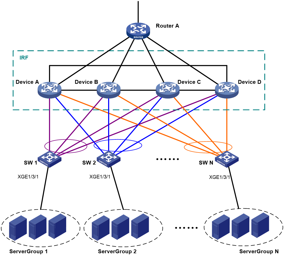
Table 3 through Table 5 show the VLAN and IP address assignment, IRF port bindings, and network topology scheme.
Table 3 VLAN and IP address assignment
|
Device |
VLAN interface |
IP address |
|
Router A |
VLAN-interface 41 |
172.24.41.2/24 |
|
Router A |
VLAN-interface 50 |
172.24.1.2/24 |
|
IRF fabric |
VLAN-interface 41 |
172.24.41.254/24 |
|
IRF fabric |
VLAN-interface 10 |
172.24.10.254/24 |
|
IRF fabric |
VLAN-interface 20 |
172.24.20.254/24 |
|
IRF fabric |
… |
… |
|
IRF fabric |
VLAN-interface N |
172.24.N.254/24 |
|
Device |
IRF port |
Neighboring IRF port |
IRF physical interfaces |
|
Device A |
IRF-port 1/1 |
IRF-port 4/2 |
XGE 1/2/2 |
|
Device A |
IRF-port 1/2 |
IRF-port 2/1 |
XGE 1/2/1 |
|
Device B |
IRF-port 2/1 |
IRF-port 1/2 |
XGE 2/2/1 |
|
Device B |
IRF-port 2/2 |
IRF-port 3/1 |
XGE 2/2/2 |
|
Device C |
IRF-port 3/1 |
IRF-port 2/2 |
XGE 3/2/2 |
|
Device C |
IRF-port 3/2 |
IRF-port 4/1 |
XGE 3/2/1 |
|
Device D |
IRF-port 4/1 |
IRF-port 3/2 |
XGE 4/2/1 |
|
Device D |
IRF-port 4/2 |
IRF-port 1/1 |
XGE 4/2/2 |
|
Device |
Neighboring device |
Port |
VLAN |
Aggregate interface |
|
IRF fabric |
SW 1 |
XGE 1/3/3 XGE 2/3/3 XGE 3/3/3 XGE 4/3/3 |
VLAN 10 |
Bridge-Aggregation 1 (LACP MAD) |
|
IRF fabric |
SW 2 |
XGE 1/3/4 XGE 2/3/4 XGE 3/3/4 XGE 4/3/4 |
VLAN 20 |
Bridge-Aggregation 2 |
|
IRF fabric |
Router A |
XGE 1/3/8 XGE 2/3/8 XGE 3/3/8 XGE 4/3/8 |
VLAN 41 |
Bridge-Aggregation 1024 |
|
SW 1 |
Server Group 1 |
XGE 1/3/1 |
VLAN 10 |
N/A |
|
SW 1 |
IRF fabric |
XGE 1/2/21 XGE 1/2/22 XGE 1/2/23 XGE 1/2/24 |
VLAN 10 |
Bridge-Aggregation 1 (LACP MAD) |
|
SW 2 |
Server Group 2 |
XGE 1/3/1 |
VLAN 20 |
N/A |
|
SW 2 |
IRF fabric |
XGE 1/2/21 XGE 1/2/22 XGE 1/2/23 XGE 1/2/24 |
VLAN 20 |
Bridge-Aggregation 1 |
|
Router A |
IRF fabric |
XGE 2/0/1 XGE 2/0/2 XGE 2/0/3 XGE 2/0/4 |
VLAN 41 |
Bridge-Aggregation 1 |
|
Router A |
Public network |
XGE 4/0/3 |
VLAN 50 |
N/A |
Analysis
For LACP MAD to run correctly, ensure that the intermediate device supports extended LACPDUs for LACP MAD.
To avoid single points of failure, use multichassis link aggregations to connect the IRF fabric to the downstream and upstream devices.
You do not need to run LACP MAD on all link aggregations. You can detect IRF split effectively by running LACP MAD on one dynamic link aggregation.
Applicable hardware and software versions
The following matrix shows the hardware and software versions to which this configuration example is applicable:
|
Hardware |
Software version |
|
S9850-G switch series |
Release 6010P03 and later |
|
S6850-G switch series S6805-G switch series |
Release 6010P03 and later |
|
S6530X switch series |
Release 8108P22 and later |
|
S5590-HI switch series |
Release 6010P03 and later |
|
S5590-EI switch series S5500V3-HI switch series |
Release 6010P03 and later |
|
S6520X-EI-G switch series S6520XP-EI-G switch series |
Release 7748 and later |
|
S5590XP-HI-G switch series |
Release 7748 and later |
|
S5560-EI-G switch series |
Release 7748 and later |
|
S5500-D-G switch series S5100-D-G switch series |
Release 6010P03 and later |
|
S5130S-HI-G switch series |
Release 6010P03 and later |
|
S5130S-EI-G switch series (except S5130S-30C-EI-G and S5130S-54C-EI-G switches) |
Release 6010P03 and later |
|
S5130S-30C-EI-G switch S5130S-54C-EI-G switch |
Release 7748 and later |
Restrictions and guidelines
When you configure LACP MAD on a link aggregation, follow these restrictions and guidelines:
· The link aggregation must use dynamic aggregation mode.
· The link aggregation must have a minimum of one member link from each member chassis.
· If the intermediate device is also an IRF fabric, you must assign the two IRF fabrics different domain IDs for correct split detection.
Procedures
Setting up the IRF fabric
1. Configure Device A:
# Shut down the physical interfaces for IRF links.
<DeviceA> system-view
[DeviceA] interface range ten-gigabitethernet 1/2/1 to ten-gigabitethernet 1/2/2
[DeviceA-if-range] shutdown
[DeviceA-if-range] quit
# Bind Ten-GigabitEthernet 1/2/2 to IRF-port 1/1.
[DeviceA] irf-port 1/1
[DeviceA-irf-port1/1] port group interface ten-gigabitethernet 1/2/2
[DeviceA-irf-port1/1] quit
# Bind Ten-GigabitEthernet 1/2/1 to IRF-port 1/2.
[DeviceA] irf-port 1/2
[DeviceA-irf-port1/2] port group interface ten-gigabitethernet 1/2/1
[DeviceA-irf-port1/2] quit
# Bring up the physical interfaces and save the running configuration.
[DeviceA] interface range ten-gigabitethernet 1/2/1 to ten-gigabitethernet 1/2/2
[DeviceA-if-range] undo shutdown
[DeviceA-if-range] quit
[DeviceA] save
# Activate the IRF port configuration.
[DeviceA] irf-port-configuration active
2. Configure Device B:
# Assign member ID 2 to Device B and reboot the device for the member ID to take effect.
<DeviceB> system-view
[DeviceB] irf member 1 renumber 2
Renumbering the member ID may result in configuration change or loss. Continue? [Y/N]:y
[DeviceB] quit
<DeviceB> reboot
# Shut down the physical interfaces for IRF links.
<DeviceB> system-view
[DeviceB] interface range ten-gigabitethernet 2/2/1 to ten-gigabitethernet 2/2/2
[DeviceB-if-range] shutdown
[DeviceB-if-range] quit
# Bind Ten-GigabitEthernet 2/2/1 to IRF-port 2/1.
[DeviceB] irf-port 2/1
[DeviceB-irf-port2/1] port group interface ten-gigabitethernet 2/2/1
[DeviceB-irf-port2/1] quit
# Bind Ten-GigabitEthernet 2/2/2 to IRF-port 2/2.
[DeviceB] irf-port 2/2
[DeviceB-irf-port2/2] port group interface ten-gigabitethernet 2/2/2
[DeviceB-irf-port2/2] quit
# Bring up the physical interfaces and save the running configuration.
[DeviceB] interface range ten-gigabitethernet 2/2/1 to ten-gigabitethernet 2/2/2
[DeviceB-if-range] undo shutdown
[DeviceB-if-range] quit
[DeviceB] save
# Connect Device B to Device A, as shown in Figure 4. (Details not shown.)
# Activate the IRF port configuration.
[DeviceB] irf-port-configuration active
3. Configure Device C:
# Assign member ID 3 to Device C and reboot the device for the member ID to take effect.
<DeviceC> system-view
[DeviceC] irf member 1 renumber 3
Renumbering the member ID may result in configuration change or loss. Continue? [Y/N]:y
[DeviceC] quit
<DeviceC> reboot
# Shut down the physical interfaces for IRF links.
<DeviceC> system-view
[DeviceC] interface range ten-gigabitethernet 3/2/1 to ten-gigabitethernet 3/2/2
[DeviceC-if-range] shutdown
[DeviceC-if-range] quit
# Bind Ten-GigabitEthernet 3/2/2 to IRF-port 3/1.
[DeviceC] irf-port 3/1
[DeviceC-irf-port3/1] port group interface ten-gigabitethernet 3/2/2
[DeviceC-irf-port3/1] quit
# Bind Ten-GigabitEthernet 3/2/1 to IRF-port 3/2.
[DeviceC] irf-port 3/2
[DeviceC-irf-port3/2] port group interface ten-gigabitethernet 3/2/1
[DeviceC-irf-port3/2] quit
# Bring up the physical interfaces and save the running configuration.
[DeviceC] interface range ten-gigabitethernet 3/2/1 to ten-gigabitethernet 3/2/2
[DeviceC-if-range] undo shutdown
[DeviceC-if-range] quit
[DeviceC] save
# Connect Device C to Device B, as shown in Figure 4. (Details not shown.)
# Activate the IRF port configuration.
[DeviceC] irf-port-configuration active
4. Configure Device D:
# Assign member ID 4 to Device D and reboot the device for the member ID to take effect.
<DeviceD> system-view
[DeviceD] irf member 1 renumber 4
Renumbering the member ID may result in configuration change or loss. Continue? [Y/N]:y
[DeviceD] quit
<DeviceD> reboot
# Shut down the physical interfaces for IRF links.
<DeviceD> system-view
[DeviceD] interface range ten-gigabitethernet 4/2/1 to ten-gigabitethernet 4/2/2
[DeviceD-if-range] shutdown
[DeviceD-if-range] quit
# Bind Ten-GigabitEthernet 4/2/1 to IRF-port 4/1.
[DeviceD] irf-port 4/1
[DeviceD-irf-port4/1] port group interface ten-gigabitethernet 4/2/1
[DeviceD-irf-port4/1] quit
# Bind Ten-GigabitEthernet 4/2/2 to IRF-port 4/2.
[DeviceD] irf-port 4/2
[DeviceD-irf-port4/2] port group interface ten-gigabitethernet 4/2/2
[DeviceD-irf-port4/2] quit
# Bring up the physical interfaces and save the running configuration.
[DeviceD] interface range ten-gigabitethernet 4/2/1 to ten-gigabitethernet 4/2/2
[DeviceD-if-range] undo shutdown
[DeviceD-if-range] quit
[DeviceD] save
# Connect Device D to Device C and Device A, as shown in Figure 4. (Details not shown.)
# Activate the IRF port configuration.
[DeviceD] irf-port-configuration active
Configuring software features
This example provides only basic software feature configuration.
Configuring the IRF fabric
After the IRF fabric is formed, the master's system name becomes the fabric's system name. You can configure software features on the fabric as you do on a standalone device.
1. Configure link aggregations:
# Create a Layer 2 dynamic aggregate interface Bridge-Aggregation 1. Enable LACP MAD on the aggregate interface.
<DeviceA> system-view
[DeviceA] interface bridge-aggregation 1
[DeviceA-Bridge-Aggregation1] link-aggregation mode dynamic
[DeviceA-Bridge-Aggregation1] mad enable
You need to assign a domain ID (range: 0-4294967295)
[Current domain is: 0]:
The assigned domain ID is: 0
[DeviceA-Bridge-Aggregation1] quit
# Assign the downlink ports that connect to SW 1 to the aggregation group of Bridge-Aggregation 1.
[DeviceA] interface range ten-gigabitethernet 1/3/3 ten-gigabitethernet 2/3/3 ten-gigabitethernet 3/3/3 ten-gigabitethernet 4/3/3
[DeviceA-if-range] port link-aggregation group 1
[DeviceA-if-range] quit
# Create Bridge-Aggregation 2. Assign the downlink ports that connect to SW 2 to the aggregation group.
[DeviceA] interface bridge-aggregation 2
[DeviceA-Bridge-Aggregation2] quit
[DeviceA] interface range ten-gigabitethernet 1/3/4 ten-gigabitethernet 2/3/4 ten-gigabitethernet 3/3/4 ten-gigabitethernet 4/3/4
[DeviceA-if-range] port link-aggregation group 2
[DeviceA-if-range] quit
# Create Bridge-Aggregation 1024. Assign the uplink ports that connect to Router A to the aggregation group.
[DeviceA] interface bridge-aggregation 1024
[DeviceA-Bridge-Aggregation1024] quit
[DeviceA] interface range ten-gigabitethernet 1/3/8 ten-gigabitethernet 2/3/8 ten-gigabitethernet 3/3/8 ten-gigabitethernet 4/3/8
[DeviceA-if-range] port link-aggregation group 1024
[DeviceA-if-range] quit
2. Configure VLANs, ports, and IP addresses:
# Create VLAN 10, assign an IP address to VLAN-interface 10, and assign Bridge-Aggregation 1 to VLAN 10.
[DeviceA] vlan 10
[DeviceA-vlan10] quit
[DeviceA] interface vlan-interface 10
[DeviceA-Vlan-interface10] ip address 172.24.10.254 24
[DeviceA-Vlan-interface10] quit
[DeviceA] interface bridge-aggregation 1
[DeviceA-Bridge-Aggregation1] port link-type trunk
[DeviceA-Bridge-Aggregation1] undo port trunk permit vlan 1
[DeviceA-Bridge-Aggregation1] port trunk permit vlan 10
[DeviceA-Bridge-Aggregation1] quit
# Create VLAN 20, assign an IP address to VLAN-interface 20, and assign Bridge-Aggregation 2 to VLAN 20.
[DeviceA] vlan 20
[DeviceA-vlan20] quit
[DeviceA] interface vlan-interface 20
[DeviceA-Vlan-interface20] ip address 172.24.20.254 24
[DeviceA-Vlan-interface20] quit
[DeviceA] interface bridge-aggregation 2
[DeviceA-Bridge-Aggregation2] port link-type trunk
[DeviceA-Bridge-Aggregation2] undo port trunk permit vlan 1
[DeviceA-Bridge-Aggregation2] port trunk permit vlan 20
[DeviceA-Bridge-Aggregation2] quit
# Create VLAN 41, assign an IP address to VLAN-interface 41, and assign Bridge-Aggregation 1024 to VLAN 41.
[DeviceA] vlan 41
[DeviceA-vlan41] quit
[DeviceA] interface vlan-interface 41
[DeviceA-Vlan-interface41] ip address 172.24.41.254 24
[DeviceA-Vlan-interface41] quit
[DeviceA] interface bridge-aggregation 1024
[DeviceA-Bridge-Aggregation1024] port access vlan 41
[DeviceA-Bridge-Aggregation1024] quit
3. Configure OSPF between the IRF fabric and Router A.
[DeviceA] interface loopback 0
[DeviceA-LoopBack0] ip address 172.24.254.1 255.255.255.255
[DeviceA-LoopBack0] quit
[DeviceA] ospf 1 router-id 172.24.254.1
[DeviceA-ospf-1] import-route direct
[DeviceA-ospf-1] area 0
[DeviceA-ospf-1-area-0.0.0.0] network 172.24.41.0 0.0.0.255
[DeviceA-ospf-1-area-0.0.0.0] quit
[DeviceA-ospf-1] quit
Configuring SW 1
1. Configure a link aggregation:
# Create Bridge-Aggregation 1, and enable the dynamic aggregation mode. You must enable the dynamic aggregation mode because this link aggregation will be used for LACP MAD.
<SW1> system-view
[SW1] interface bridge-aggregation 1
[SW1-Bridge-Aggregation1] link-aggregation mode dynamic
[SW1-Bridge-Aggregation1] quit
# Assign uplink ports to Bridge-Aggregation 1.
[SW1] interface range ten-gigabitethernet 1/2/21 to ten-gigabitethernet 1/2/24
[SW1-if-range] port link-aggregation group 1
[SW1-if-range] quit
2. Configure VLANs, ports, and IP addresses:
# Create all VLANs.
[SW1] vlan all
# Configure the aggregate interface that connects to the IRF fabric.
[SW1] interface bridge-aggregation 1
[SW1-Bridge-Aggregation1] port link-type trunk
[SW1-Bridge-Aggregation1] undo port trunk permit vlan 1
[SW1-Bridge-Aggregation1] port trunk permit vlan 10
[SW1-Bridge-Aggregation1] quit
# Configure the port that connects to Server Group 1.
[SW1] interface ten-gigabitethernet 1/3/1
[SW1-Ten-GigabitEthernet1/3/1] port link-type trunk
[SW1-Ten-GigabitEthernet1/3/1] port trunk permit vlan all
[SW1-Ten-GigabitEthernet1/3/1] undo port trunk permit vlan 1
[SW1-Ten-GigabitEthernet1/3/1] quit
Configuring SW 2
1. Configure a link aggregation:
# Create Bridge-Aggregation 1.
<SW2> system-view
[SW2] interface bridge-aggregation 1
[SW2-Bridge-Aggregation1] quit
# Assign uplink ports to Bridge-Aggregation 1.
[SW2] interface range ten-gigabitethernet 1/2/21 to ten-gigabitethernet 1/2/24
[SW2-if-range] port link-aggregation group 1
[SW2-if-range] quit
2. Configure VLANs, ports, and IP addresses:
# Create all VLANs.
[SW2] vlan all
# Configure VLAN settings on the uplink aggregate interface that connects to the IRF fabric.
[SW2] interface bridge-aggregation 1
[SW2-Bridge-Aggregation1] port link-type trunk
[SW2-Bridge-Aggregation1] undo port trunk permit vlan 1
[SW2-Bridge-Aggregation1] port trunk permit vlan 20
[SW2-Bridge-Aggregation1] quit
# Configure VLAN settings on the port that connects to Server Group 2.
[SW2] interface ten-gigabitethernet 1/3/1
[SW2-Ten-GigabitEthernet1/3/1] port link-type trunk
[SW2-Ten-GigabitEthernet1/3/1] port trunk permit vlan all
[SW2-Ten-GigabitEthernet1/3/1] undo port trunk permit vlan 1
[SW2-Ten-GigabitEthernet1/3/1] quit
Configuring Router A
In this example, the egress router configuration only includes the connection to the IRF fabric.
1. Configure link aggregation:
# Create Bridge-Aggregation 1.
<RouterA> system-view
[RouterA] interface bridge-aggregation 1
[RouterA-Bridge-Aggregation1] quit
# Assign the downlink ports that connect to the IRF fabric to Bridge-Aggregation 1.
[RouterA] interface range ten-gigabitethernet 2/0/1 to ten-gigabitethernet 2/0/4
[RouterA-if-range] port link-aggregation group 1
[RouterA-if-range] quit
2. Configure VLANs, ports, and IP addresses:
# Create VLAN 41, assign an IP address to VLAN-interface 41, and assign Bridge-Aggregation 1 to VLAN 41.
[RouterA] vlan 41
[RouterA-vlan41] quit
[RouterA] interface vlan-interface 41
[RouterA-vlan-interface41] ip address 172.24.41.2 24
[RouterA-vlan-interface41] quit
[RouterA] interface bridge-aggregation 1
[RouterA-Bridge-Aggregation1] port access vlan 41
[RouterA-Bridge-Aggregation1] quit
# Create VLAN 50, assign an IP address to VLAN-interface 50, and assign Ten-GigabitEthernet 4/0/3 to VLAN 50.
[RouterA] vlan 50
[RouterA-vlan50] quit
[RouterA] interface vlan-interface 50
[RouterA-vlan-interface50] ip address 172.24.1.2 24
[RouterA-vlan-interface50] quit
[RouterA] interface ten-gigabitethernet 4/0/3
[RouterA-Ten-GigabitEthernet4/0/3] port link-mode bridge
[RouterA-Ten-GigabitEthernet4/0/3] port access vlan 50
[RouterA-Ten-GigabitEthernet4/0/3] quit
3. Configure OSPF between the IRF fabric and Router A.
[RouterA] interface loopback 0
[RouterA-LoopBack0] ip addresss 172.24.254.2 255.255.255.255
[RouterA-LoopBack0] quit
[RouterA] ospf 1 router-id 172.24.254.2
[RouterA-ospf-1] import-route direct
[RouterA-ospf-1] area 0
[RouterA-ospf-1-area-0.0.0.0] network 172.24.41.0 0.0.0.255
[RouterA-ospf-1-area-0.0.0.0] quit
[RouterA-ospf-1] quit
Verifying the configuration
Verify the IRF and multichassis link aggregation configuration.
Verifying the IRF function
# Execute the display irf topology command.
<DeviceA> display irf topology
Topology Info
-------------------------------------------------------------------------
IRF-Port1 IRF-Port2
MemberID Link neighbor Link neighbor Belong To
1 UP 4 UP 2 00e0-fc0f-8c08
4 UP 3 UP 1 00e0-fc0f-8c08
3 UP 2 UP 4 00e0-fc0f-8c08
2 UP 1 UP 3 00e0-fc0f-8c08
The output shows that all the IRF links are in UP state. The four-chassis IRF fabric is established.
Verifying the link backup function of multichassis aggregations
# Shut down Ten-GigabitEthernet 1/3/8, the port connected to Router A.
[DeviceA] interface ten-gigabitethernet 1/3/8
[DeviceA-Ten-GigabitEthernet1/3/8] shutdown
# Ping an IP address on the public network from a PC in Server Group 1.
C:\Users>ping 202.108.22.5 -t
Pinging 202.108.22.5 with 32 bytes of data:
Reply from 202.108.22.5: bytes=32 time=1ms TTL=122
Reply from 202.108.22.5: bytes=32 time=13ms TTL=122
Reply from 202.108.22.5: bytes=32 time<1ms TTL=122
Request timed out.
Request timed out.
Request timed out.
Reply from 202.108.22.5: bytes=32 time<1ms TTL=122
Reply from 202.108.22.5: bytes=32 time<1ms TTL=122
Reply from 202.108.22.5: bytes=32 time<1ms TTL=122
The output shows that the address can be pinged after transient traffic disruption.
# Bring up Ten-GigabitEthernet 1/3/8 and shut down Ten-GigabitEthernet 2/3/8.
[DeviceA-Ten-GigabitEthernet1/3/8] undo shutdown
[DeviceA-Ten-GigabitEthernet1/3/8] quit
[DeviceA] interface ten-gigabitethernet 2/3/8
[DeviceA-Ten-GigabitEthernet2/3/8] shutdown
# Ping the IP address on the public network from the PC.
C:\Users>ping 202.108.22.5 -t
Pinging 202.108.22.5 with 32 bytes of data:
Reply from 202.108.22.5: bytes=32 time=1ms TTL=122
Reply from 202.108.22.5: bytes=32 time=13ms TTL=122
Reply from 202.108.22.5: bytes=32 time<1ms TTL=122
Request timed out.
Request timed out.
Request timed out.
Reply from 202.108.22.5: bytes=32 time<1ms TTL=122
Reply from 202.108.22.5: bytes=32 time<1ms TTL=122
Reply from 202.108.22.5: bytes=32 time<1ms TTL=122
The output shows that the address can be pinged after transient traffic disruption.
Configuration files
· IRF fabric:
#
irf mac-address persistent always
irf auto-update enable
undo irf link-delay
irf member 1 priority 1
irf member 2 priority 1
irf member 3 priority 1
irf member 4 priority 1
#
ospf 1 router-id 172.24.254.1
import-route direct
area 0.0.0.0
network 172.24.41.0 0.0.0.255
#
vlan 10
#
vlan 20
#
vlan 41
#
irf-port 1/1
port group interface Ten-GigabitEthernet1/2/2 mode enhanced
#
irf-port 1/2
port group interface Ten-GigabitEthernet1/2/1 mode enhanced
#
irf-port 2/1
port group interface Ten-GigabitEthernet2/2/1 mode enhanced
#
irf-port 2/2
port group interface Ten-GigabitEthernet2/2/2 mode enhanced
#
irf-port 3/1
port group interface Ten-GigabitEthernet3/2/2 mode enhanced
#
irf-port 3/2
port group interface Ten-GigabitEthernet3/2/1 mode enhanced
#
irf-port 4/1
port group interface Ten-GigabitEthernet4/2/1 mode enhanced
#
irf-port 4/2
port group interface Ten-GigabitEthernet4/2/2 mode enhanced
#
interface bridge-aggregation 1
port link-type trunk
undo port trunk permit vlan 1
port trunk permit vlan 10
mad enable
link-aggregation mode dynamic
#
interface bridge-aggregation 2
port link-type trunk
undo port trunk permit vlan 1
port trunk permit vlan 20
#
interface bridge-aggregation 1024
port access vlan 41
#
interface loopback 0
ip address 172.24.254.1 255.255.255.255
#
interface vlan-interface 10
ip address 172.24.10.254 24
#
interface vlan-interface 20
ip address 172.24.20.254 24
#
interface vlan-interface 41
ip address 172.24.41.254 24
#
interface Ten-GigabitEthernet 1/3/3
port link-mode bridge
port link-type trunk
undo port trunk permit vlan 1
port trunk permit vlan 10
port link-aggregation group 1
#
interface Ten-GigabitEthernet 1/3/4
port link-mode bridge
port link-type trunk
undo port trunk permit vlan 1
port trunk permit vlan 20
port link-aggregation group 2
#
interface Ten-GigabitEthernet 1/3/8
port link-mode bridge
port access vlan 41
port link-aggregation group 1024
#
interface Ten-GigabitEthernet 2/3/3
port link-mode bridge
port link-type trunk
undo port trunk permit vlan 1
port trunk permit vlan 10
port link-aggregation group 1
#
interface Ten-GigabitEthernet 2/3/4
port link-mode bridge
port link-type trunk
undo port trunk permit vlan 1
port trunk permit vlan 20
port link-aggregation group 2
#
interface Ten-GigabitEthernet 2/3/8
port link-mode bridge
port access vlan 41
port link-aggregation group 1024
#
interface Ten-GigabitEthernet 3/3/3
port link-mode bridge
port link-type trunk
undo port trunk permit vlan 1
port trunk permit vlan 10
port link-aggregation group 1
#
interface Ten-GigabitEthernet 3/3/4
port link-mode bridge
port link-type trunk
undo port trunk permit vlan 1
port trunk permit vlan 20
port link-aggregation group 2
#
interface Ten-GigabitEthernet 3/3/8
port link-mode bridge
port access vlan 41
port link-aggregation group 1024
#
interface Ten-GigabitEthernet 4/3/3
port link-mode bridge
port link-type trunk
undo port trunk permit vlan 1
port trunk permit vlan 10
port link-aggregation group 1
#
interface Ten-GigabitEthernet 4/3/4
port link-mode bridge
port link-type trunk
undo port trunk permit vlan 1
port trunk permit vlan 20
port link-aggregation group 2
#
interface Ten-GigabitEthernet 4/3/8
port link-mode bridge
port access vlan 41
port link-aggregation group 1024
#
· SW 1:
#
vlan 1
#
vlan 2 to 4094
#
interface Ten-GigabitEthernet1/3/1
port link-mode bridge
port link-type trunk
undo port trunk permit vlan 1
port trunk permit vlan 2 to 4094
#
interface bridge-aggregation 1
port link-type trunk
undo port trunk permit vlan 1
port trunk permit vlan 10
link-aggregation mode dynamic
#
interface Ten-GigabitEthernet 1/2/21
port link-mode bridge
port link-type trunk
undo port trunk permit vlan 1
port trunk permit vlan 10
port link-aggregation group 1
#
interface Ten-GigabitEthernet 1/2/22
port link-mode bridge
port link-type trunk
undo port trunk permit vlan 1
port trunk permit vlan 10
port link-aggregation group 1
#
interface Ten-GigabitEthernet 1/2/23
port link-mode bridge
port link-type trunk
undo port trunk permit vlan 1
port trunk permit vlan 10
port link-aggregation group 1
#
interface Ten-GigabitEthernet 1/2/24
port link-mode bridge
port link-type trunk
undo port trunk permit vlan 1
port trunk permit vlan 10
port link-aggregation group 1
#
· SW 2:
#
vlan 1
#
vlan 2 to 4094
#
interface Ten-GigabitEthernet1/3/1
port link-mode bridge
port link-type trunk
undo port trunk permit vlan 1
port trunk permit vlan 2 to 4094
#
interface bridge-aggregation 1
port link-type trunk
undo port trunk permit vlan 1
port trunk permit vlan 20
#
interface Ten-GigabitEthernet 1/2/21
port link-mode bridge
port link-type trunk
undo port trunk permit vlan 1
port trunk permit vlan 20
port link-aggregation group 1
#
interface Ten-GigabitEthernet 1/2/22
port link-mode bridge
port link-type trunk
undo port trunk permit vlan 1
port trunk permit vlan 20
port link-aggregation group 1
#
interface Ten-GigabitEthernet 1/2/23
port link-mode bridge
port link-type trunk
undo port trunk permit vlan 1
port trunk permit vlan 20
port link-aggregation group 1
#
interface Ten-GigabitEthernet 1/2/24
port link-mode bridge
port link-type trunk
undo port trunk permit vlan 1
port trunk permit vlan 20
port link-aggregation group 1
#
· Router A:
#
ospf 1 router-id 172.24.254.2
import-route direct
area 0.0.0.0
network 172.24.41.0 0.0.0.255
#
vlan 41
#
vlan 50
#
interface bridge-aggregation 1
port access vlan 41
#
interface loopback 0
ip address 172.24.254.2 255.255.255.255
#
interface vlan-interface 41
ip address 172.24.41.2 24
#
interface vlan-interface 50
ip address 172.24.1.2 24
#
interface Ten-GigabitEthernet 2/0/1
port link-mode bridge
port access vlan 41
port link-aggregation group 1
#
interface Ten-GigabitEthernet 2/0/2
port link-mode bridge
port access vlan 41
port link-aggregation group 1
#
interface Ten-GigabitEthernet 2/0/3
port link-mode bridge
port access vlan 41
port link-aggregation group 1
#
interface Ten-GigabitEthernet 2/0/4
port link-mode bridge
port access vlan 41
port link-aggregation group 1
#
interface Ten-GigabitEthernet 2/0/12
port link-mode bridge
port access vlan 50
#
Example: Upgrading a two-chassis IRF fabric to a four-chassis IRF fabric (BFD MAD)
Network configuration
Upgrade a two-chassis IRF fabric (see Figure 5) to a four-chassis IRF fabric (see Figure 7) by performing one of the following tasks:
· Merge two two-chassis IRF fabrics.
· Add two chassis to the existing two-chassis IRF fabric.
Configure BFD MAD on the four-chassis IRF fabric, and set up a BFD MAD link between the intermediate device and each member device. BFD MAD uses common Ethernet ports.
Figure 5 Two-chassis IRF fabric
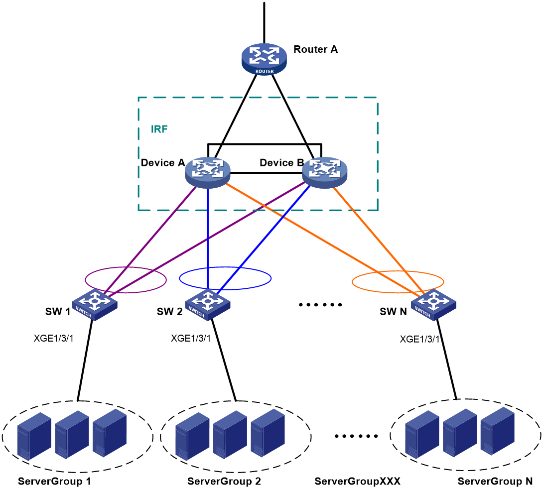
Figure 6 Upgrading the two-chassis IRF fabric to a four-chassis IRF fabric

Figure 7 BFD MAD-enabled four-chassis IRF fabric
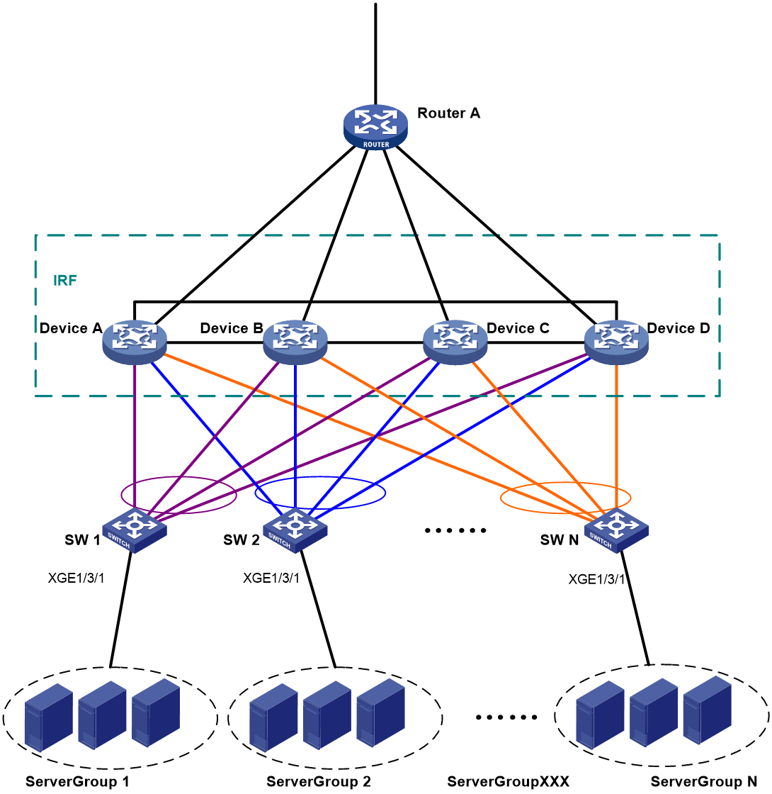
Table 6 Network topology (partial)
|
Device |
Neighboring device |
Port |
BFD MAD VLAN |
|
IRF fabric |
SW 2 |
XGE 1/3/1 XGE 2/3/1 XGE 3/3/1 XGE 4/3/1 |
VLAN 13 |
|
SW 2 |
IRF fabric |
XGE 1/2/41 XGE 1/2/42 XGE 1/2/43 XGE 1/2/44 |
VLAN 13 |
For more information about the VLAN and IP assignment, port bindings, and network topology scheme, see Table 3, Table 4, and Table 5.
Analysis
Because each IRF member must have a unique member ID on the IRF fabric, you must verify that the member ID assignment schemes of the two IRF fabrics do not conflict. If the schemes conflict, renumber the member devices in one IRF fabric to ensure that the two IRF fabrics can merge.
To avoid single points of failure, use multichassis link aggregations to connect the IRF fabric to the downstream and upstream devices.
If a downstream or upstream device can process extended LACPDUs for LACP MAD, you can use LACP MAD for IRF split detection. If none of the upstream or downstream devices can process extended LACPDUs, you can use BFD MAD instead.
In this example, BFD MAD uses common Ethernet ports. You can deploy BFD MAD by using the following methods:
· Connect all member chassis with dedicated BFD MAD links into a full mesh topology. This method is suitable for two-chassis IRF fabrics.
· Set up a dedicated BFD MAD link with an intermediate device for each IRF member chassis. This method is suitable for three- or four-chassis IRF fabrics because it uses fewer physical ports than the previous method.
The intermediate device forwards BFD MAD packets transparently. You must assign all BFD MAD links to the VLAN used for BFD MAD.
Applicable hardware and software versions
The following matrix shows the hardware and software versions to which this configuration example is applicable:
|
Hardware |
Software version |
|
S9850-G switch series |
Release 6010P03 and later |
|
S6850-G switch series S6805-G switch series |
Release 6010P03 and later |
|
S6530X switch series |
Release 8108P22 and later |
|
S5590-HI switch series |
Release 6010P03 and later |
|
S5590-EI switch series S5500V3-HI switch series |
Release 6010P03 and later |
|
S6520X-EI-G switch series S6520XP-EI-G switch series |
Release 7748 and later |
|
S5590XP-HI-G switch series |
Release 7748 and later |
|
S5560-EI-G switch series |
Release 7748 and later |
|
S5500-D-G switch series S5100-D-G switch series |
Release 6010P03 and later |
|
S5130S-HI-G switch series |
Release 6010P03 and later |
|
S5130S-EI-G switch series (except S5130S-30C-EI-G and S5130S-54C-EI-G switches) |
Release 6010P03 and later |
|
S5130S-30C-EI-G switch S5130S-54C-EI-G switch |
Release 7748 and later |
Restrictions and guidelines
Disable the spanning tree feature on any Layer 2 Ethernet ports in the BFD MAD VLAN. The MAD feature is mutually exclusive with the spanning tree feature.
Procedures
Use one of the following methods to upgrade a two-chassis IRF fabric to a four-chassis IRF fabric:
· Adding two chassis to a two-chassis IRF fabric
· Merging two two-chassis IRF fabrics
Adding two chassis to a two-chassis IRF fabric
1. Configure the IRF fabric
# Shut down the physical interfaces to be used for establishing IRF connections to Device C and Device D.
<DeviceA> system-view
[DeviceA] interface ten-gigabitethernet 1/2/2
[DeviceA-Ten-GigabitEthernet1/2/2] shutdown
[DeviceA-Ten-GigabitEthernet1/2/2] quit
[DeviceA] interface ten-gigabitEthernet 2/2/2
[DeviceA-Ten-GigabitEthernet2/2/2] undo shutdown
[DeviceA-Ten-GigabitEthernet2/2/2] quit
# Bind Ten-GigabitEthernet 1/2/2 to IRF-port 1/1.
[DeviceA] irf-port 1/1
[DeviceA-irf-port1/1] port group interface ten-gigabitethernet 1/2/2
[DeviceA-irf-port1/1] quit
# Bind Ten-GigabitEthernet 2/2/2 to IRF-port 2/2.
[DeviceA] irf-port 2/2
[DeviceA-irf-port2/2] port group interface ten-gigabitethernet2/2/2
[DeviceA-irf-port2/2] quit
# Bring up the IRF physical interfaces and save the configuration.
[DeviceA] interface ten-gigabitethernet 1/2/2
[DeviceA-Ten-GigabitEthernet1/2/2] undo shutdown
[DeviceA-Ten-GigabitEthernet1/2/2] quit
[DeviceA] interface ten-gigabitEthernet 2/2/2
[DeviceA-Ten-GigabitEthernet2/2/2] undo shutdown
[DeviceA-Ten-GigabitEthernet2/2/2] quit
[DeviceA] save
# Activate the IRF port configuration.
[DeviceA] irf-port-configuration active
2. Configure IRF on Device C:
# Assign member ID 3 to Device C and reboot the device for the member ID to take effect.
<DeviceC> system-view
[DeviceC] irf member 1 renumber 3
Renumbering the member ID may result in configuration change or loss. Continue? [Y/N]:y
[DeviceC] quit
<DeviceC> reboot
# Shut down the physical interfaces for IRF links.
<DeviceC> system-view
[DeviceC] interface range ten-gigabitethernet 3/2/1 to ten-gigabitethernet 3/2/2
[DeviceC-if-range] shutdown
[DeviceC-if-range] quit
# Bind Ten-GigabitEthernet 3/2/2 to IRF-port 3/1.
[DeviceC] irf-port 3/1
[DeviceC-irf-port3/1] port group interface ten-gigabitethernet 3/2/2
[DeviceC-irf-port3/1] quit
# Bind Ten-GigabitEthernet 3/2/1 to IRF-port 3/2.
[DeviceC] irf-port 3/2
[DeviceC-irf-port3/2] port group interface ten-gigabitethernet 3/2/1
[DeviceC-irf-port3/2] quit
# Bring up the physical interfaces and save the configuration.
[DeviceC] interface range ten-gigabitethernet 3/2/1 to ten-gigabitethernet 3/2/2
[DeviceC-if-range] undo shutdown
[DeviceC-if-range] quit
[DeviceC] save
# Connect Device C to Device B, as shown in Figure 7. (Details not shown.)
# Activate the IRF port configuration.
[DeviceC] irf-port-configuration active
3. Configure IRF on Device D:
# Assign member ID 4 to Device D and reboot the device for the member ID to take effect.
<DeviceD> system-view
[DeviceD] irf member 1 renumber 4
Renumbering the member ID may result in configuration change or loss. Continue? [Y/N]:y
[DeviceD] quit
<DeviceD> reboot
# Shut down the physical interfaces for IRF links.
<DeviceD> system-view
[DeviceD] interface range ten-gigabitethernet 4/2/1 to ten-gigabitethernet 4/2/2
[DeviceD-if-range] shutdown
[DeviceD-if-range] quit
# Bind Ten-GigabitEthernet 4/2/1 to IRF-port 4/1.
[DeviceD] irf-port 4/1
[DeviceD-irf-port4/1] port group interface ten-gigabitethernet 4/2/1
[DeviceD-irf-port4/1] quit
# Bind Ten-GigabitEthernet 4/2/2 to IRF-port 4/2.
[DeviceD] irf-port 4/2
[DeviceD-irf-port4/2] port group interface ten-gigabitethernet 4/2/2
[DeviceD-irf-port4/2] quit
# Bring up the physical interfaces and save the configuration.
[DeviceD] interface range ten-gigabitethernet 4/2/1 to ten-gigabitethernet 4/2/2
[DeviceD-if-range] undo shutdown
[DeviceD-if-range] quit
[DeviceD] save
# Connect Device D to Device A and Device C, as shown in Figure 7. (Details not shown.)
# Activate the IRF port configuration.
[DeviceD] irf-port-configuration active
Merging two two-chassis IRF fabrics
1. Configure the IRF fabric that has Device A and Device B:
# Shut down the physical interfaces to be used for establishing IRF connections to Device C and Device D.
<DeviceA> system-view
[DeviceA] interface ten-gigabitethernet 1/2/2
[DeviceA-Ten-GigabitEthernet1/2/2] shutdown
[DeviceA-Ten-GigabitEthernet1/2/2] quit
[DeviceA] interface ten-gigabitethernet 2/2/2
[DeviceA-Ten-GigabitEthernet2/2/2] shutdown
[DeviceA-Ten-GigabitEthernet2/2/2] quit
# Bind Ten-GigabitEthernet 1/2/2 to IRF-port 1/1.
[DeviceA] irf-port 1/1
[DeviceA-irf-port1/1] port group interface ten-gigabitethernet 1/2/2
[DeviceA-irf-port1/1] quit
# Bind Ten-GigabitEthernet 2/2/2 to IRF-port 2/2.
[DeviceA] irf-port 2/2
[DeviceA-irf-port2/2] port group interface ten-gigabitethernet 2/2/2
[DeviceA-irf-port2/2] quit
# Shut down the IRF physical interfaces and then save the running configuration.
[DeviceA] interface ten-gigabitethernet 1/2/2
[DeviceA-Ten-GigabitEthernet1/2/2] undo shutdown
[DeviceA-Ten-GigabitEthernet1/2/2] quit
[DeviceA] interface ten-gigabitethernet 2/2/2
[DeviceA-Ten-GigabitEthernet2/2/2] undo shutdown
[DeviceA-Ten-GigabitEthernet2/2/2] quit
[DeviceA] save
# Activate the IRF port configuration.
[DeviceA] irf-port-configuration active
2. Configure the IRF fabric that has Device C and Device D:
# Change the member IDs to 3 and 4 for Device C and Device D, respectively.
<DeviceC> system-view
[DeviceC] irf member 1 renumber 3
Renumbering the member ID may result in configuration change or loss. Continue?[
Y/N]y
[DeviceC] irf member 2 renumber 4
Renumbering the member ID may result in configuration change or loss. Continue?[
Y/N]y
# Save the running configuration and reboot the IRF fabric.
[DeviceC] quit
<DeviceC> reboot
# Shut down the physical interfaces to be used for establishing IRF connections to Device A and Device B.
<DeviceC> system-view
[DeviceC] interface ten-gigabitethernet 3/2/2
[DeviceC-Ten-GigabitEthernet3/2/2] shutdown
[DeviceC-Ten-GigabitEthernet3/2/2] quit
[DeviceC] interface ten-gigabitethernet 4/2/2
[DeviceC-Ten-GigabitEthernet4/2/2] shutdown
[DeviceC-Ten-GigabitEthernet4/2/2] quit
# Bind Ten-GigabitEthernet 3/2/2 to IRF-port 3/1.
[DeviceC] irf-port 3/1
[DeviceC-irf-port3/1] port group interface ten-gigabitethernet 3/2/2
[DeviceC-irf-port3/1] quit
# Bind Ten-GigabitEthernet 4/2/2 to IRF-port 4/2.
[DeviceD] irf-port 4/2
[DeviceD-irf-port4/2] port group interface ten-gigabitethernet4/2/2
[DeviceD-irf-port4/2] quit
# Bring up the IRF physical interfaces, and then save the configuration.
[DeviceC] interface ten-gigabitethernet 3/2/2
[DeviceC-Ten-GigabitEthernet3/2/2] undo shutdown
[DeviceC-Ten-GigabitEthernet3/2/2] quit
[DeviceC] interface ten-gigabitethernet 4/2/2
[DeviceC-Ten-GigabitEthernet4/2/2] undo shutdown
[DeviceC-Ten-GigabitEthernet4/2/2] quit
[DevicC] save
# Connect Device C to Device B, and connect Device A to Device D, as shown in Figure 7. (Details not shown.)
# Activate the IRF port configuration.
[DeviceC] irf-port-configuration active
Configuring BFD MAD
After the IRF fabric is formed, the master's system name becomes the fabric's system name (Device A in this example). You can configure software features on the fabric as you do on a standalone device.
|
|
IMPORTANT: Do not use the BFD MAD VLAN and its member ports for any purpose other than BFD MAD. |
# Set the IRF link down report delay to 0 seconds.
[DeviceA] irf link-delay 0
# Create VLAN 13, and enable BFD MAD on VLAN-interface 13.
[DeviceA] vlan 13
[DeviceA-vlan13] quit
[DeviceA] interface Vlan-interface 13
[DeviceA-Vlan-interface13] mad bfd enable
# Configure a MAD IP address for each member device on VLAN-interface 13.
[DeviceA-Vlan-interface13] mad ip address 172.1.1.1 24 member 1
[DeviceA-Vlan-interface13] mad ip address 172.1.1.2 24 member 2
[DeviceA-Vlan-interface13] mad ip address 172.1.1.3 24 member 3
[DeviceA-Vlan-interface13] mad ip address 172.1.1.4 24 member 4
[DeviceA-Vlan-interface13] undo shutdown
[DeviceA-Vlan-interface13] quit
# Assign the ports that connect to SW 2 to VLAN 13. Disable the spanning tree feature on the ports.
[DeviceA] interface range ten-gigabitethernet 1/3/1 ten-gigabitethernet 2/3/1 ten-gigabitethernet 3/3/1 ten-gigabitethernet 4/3/1
[DeviceA-if-range] undo stp enable
[DeviceA-if-range] port access vlan 13
[DeviceA-if-range] quit
Configuring downlink services
In this example, the feature settings on the original IRF fabrics were cleared. In practice, you do not need to reconfigure all settings you have configured, such as IP addresses.
Configuring the IRF fabric
1. Configure link aggregations:
# Create Bridge-Aggregation 1.
<DeviceA> system-view
[DeviceA] interface bridge-aggregation 1
[DeviceA-Bridge-Aggregation1] quit
# Assign the downlink ports that connect to SW 1 to Bridge-Aggregation 1.
[DeviceA] interface range ten-gigabitethernet 1/3/3 ten-gigabitethernet 2/3/3 ten-gigabitethernet 3/3/3 ten-gigabitethernet 4/3/3
[DeviceA-if-range] port link-aggregation group 1
[DeviceA-if-range] quit
# Create Bridge-Aggregation 2.
[DeviceA] interface bridge-aggregation 2
[DeviceA-Bridge-Aggregation2] quit
# Assign the downlink ports that connect to SW 2 to Bridge-Aggregation 2.
[DeviceA] interface range ten-gigabitethernet 1/3/4 ten-gigabitethernet 2/3/4 ten-gigabitethernet 3/3/4 ten-gigabitethernet 4/3/4
[DeviceA-if-range] port link-aggregation group 2
[DeviceA-if-range] quit
2. Configure VLANs, ports, and IP addresses:
# Create VLAN 10, assign an IP address to VLAN-interface 10 towards SW 1, and assign Bridge-Aggregation 1 to VLAN 10.
[DeviceA] vlan 10
[DeviceA-vlan10] quit
[DeviceA] interface vlan-interface 10
[DeviceA-Vlan-interface10] ip address 172.24.10.254 24
[DeviceA-Vlan-interface10] quit
[DeviceA] interface bridge-aggregation 1
[DeviceA-Bridge-Aggregation1] port link-type trunk
[DeviceA-Bridge-Aggregation1] undo port trunk permit vlan 1
[DeviceA-Bridge-Aggregation1] port trunk permit vlan 10
[DeviceA-Bridge-Aggregation1] quit
# Create VLAN 20, assign an IP address to VLAN-interface 20 towards SW 2, and assign Bridge-Aggregation 2 to VLAN 20.
[DeviceA] vlan 20
[DeviceA-vlan20] quit
[DeviceA] interface vlan-interface 20
[DeviceA-Vlan-interface20] ip address 172.24.20.254 24
[DeviceA-Vlan-interface20] quit
[DeviceA] interface bridge-aggregation 2
[DeviceA-Bridge-Aggregation2] port link-type trunk
[DeviceA-Bridge-Aggregation2] undo port trunk permit vlan 1
[DeviceA-Bridge-Aggregation2] port trunk permit vlan 20
[DeviceA-Bridge-Aggregation2] quit
Configuring SW 1
1. Configure a link aggregation:
# Create Bridge-Aggregation 1.
<SW1> system-view
[SW1] interface bridge-aggregation 1
[SW1-Bridge-Aggregation1] quit
# Assign the uplink ports to Bridge-Aggregation 1.
[SW1] interface range ten-gigabitethernet 1/2/21 to ten-gigabitethernet 1/2/24
[SW1-if-range] port link-aggregation group 1
[SW1-if-range] quit
2. Configure VLANs, ports, and IP addresses:
# Create all VLANs.
[SW1] vlan all
# Configure VLAN settings on Bridge-Aggregation 1.
[SW1] interface bridge-aggregation 1
[SW1-Bridge-Aggregation1] port link-type trunk
[SW1-Bridge-Aggregation1] undo port trunk permit vlan 1
[SW1-Bridge-Aggregation1] port trunk permit vlan 10
[SW1-Bridge-Aggregation1] quit
# Configure VLAN settings for the port that connects to Server Group 1.
[SW1] interface ten-gigabitethernet 1/3/1
[SW1-Ten-GigabitEthernet1/3/1] port link-type trunk
[SW1-Ten-GigabitEthernet1/3/1] port trunk permit vlan all
[SW1-Ten-GigabitEthernet1/3/1] undo port trunk permit vlan 1
[SW1-Ten-GigabitEthernet1/3/1] quit
Configuring SW 2
1. Configure a link aggregation:
# Create Bridge-Aggregation 1.
<SW2> system-view
[SW2] interface bridge-aggregation 1
[SW2-Bridge-Aggregation1] quit
# Assign the uplink ports to Bridge-Aggregation 1.
[SW2] interface range ten-gigabitethernet 1/2/21 to ten-gigabitethernet 1/2/24
[SW2-if-range] port link-aggregation group 1
[SW2-if-range] quit
2. Configure VLANs, ports, and IP addresses:
# Create all VLANs.
[SW2] vlan all
# Configure VLAN settings on Bridge-Aggregation 1.
[SW2] interface bridge-aggregation 1
[SW2-Bridge-Aggregation1] port link-type trunk
[SW2-Bridge-Aggregation1] undo port trunk permit vlan 1
[SW2-Bridge-Aggregation1] port trunk permit vlan 20
[SW2-Bridge-Aggregation1] quit
# Configure the port that connects to Server Group 2.
[SW2] interface ten-gigabitethernet 1/3/1
[SW2-Ten-GigabitEthernet1/3/1] port link-type trunk
[SW2-Ten-GigabitEthernet1/3/1] port trunk permit vlan all
[SW2-Ten-GigabitEthernet1/3/1] undo port trunk permit vlan 1
[SW2-Ten-GigabitEthernet1/3/1] quit
# Assign the ports used for BFD MAD to VLAN 13.
[SW2] interface range ten-gigabitethernet 1/2/41 to ten-gigabitethernet 1/2/44
[SW2-if-range] port access vlan 13
[SW2-if-range] quit
Configuring uplink services
In this example, the feature settings on the original IRF fabrics were cleared. In practice, you do not need to reconfigure all settings you have configured, such as IP addresses.
Configuring the IRF fabric
1. Configure link aggregations:
# Create Bridge-Aggregation 1024.
[DeviceA] interface bridge-aggregation 1024
[DeviceA-Bridge-Aggregation1024] quit
# Assign the uplink ports that connect to Router A to the aggregation group.
[DeviceA] interface range ten-gigabitethernet 1/3/8 ten-gigabitethernet 2/3/8 ten-gigabitethernet 3/3/8 ten-gigabitethernet 4/3/8
[DeviceA-if-range] port link-aggregation group 1024
[DeviceA-if-range] quit
2. Configure VLANs, ports, and IP addresses for connectivity to Router A:
# Create VLAN 41, assign an IP address to VLAN-interface 41, and assign Bridge-Aggregation 1024 to VLAN 41.
[DeviceA] vlan 41
[DeviceA-vlan41] quit
[DeviceA] interface vlan-interface 41
[DeviceA-Vlan-interface41] ip address 172.24.41.254 24
[DeviceA-Vlan-interface41] quit
[DeviceA] interface bridge-aggregation 1024
[DeviceA-Bridge-Aggregation1024] port access vlan 41
[DeviceA-Bridge-Aggregation1024] quit
3. Configure OSPF between the IRF fabric and Router A.
[DeviceA] interface loopback 0
[DeviceA-LoopBack0] ip address 172.24.254.1 255.255.255.255
[DeviceA-LoopBack0] quit
[DeviceA] ospf 1 router-id 172.24.254.1
[DeviceA-ospf-1] import-route direct
[DeviceA-ospf-1] area 0
[DeviceA-ospf-1-area-0.0.0.0] network 172.24.41.0 0.0.0.255
[DeviceA-ospf-1-area-0.0.0.0] quit
[DeviceA-ospf-1] quit
Configuring Router A
In this example, the egress router configuration only includes the connection to the IRF fabric.
1. Configure link aggregation:
# Create Bridge-Aggregation 1.
<RouterA> system-view
[RouterA] interface bridge-aggregation 1
[RouterA-Bridge-Aggregation1] quit
# Assign the downlink ports that connect to the IRF fabric to Bridge-Aggregation 1.
[RouterA] interface range ten-gigabitethernet 2/0/1 to ten-gigabitethernet 2/0/4
[RouterA-if-range] port link-aggregation group 1
[RouterA-if-range] quit
2. Configure VLANs, ports, and IP addresses:
# Create VLAN 41, assign an IP address to VLAN-interface 41, and assign Bridge-Aggregation 1 to VLAN 41.
[RouterA] vlan 41
[RouterA-vlan41] quit
[RouterA] interface vlan-interface 41
[RouterA-vlan-interface41] ip address 172.24.41.2 24
[RouterA-vlan-interface41] quit
[RouterA] interface bridge-aggregation 1
[RouterA-Bridge-Aggregation1] port access vlan 41
[RouterA-Bridge-Aggregation1] quit
# Create VLAN 50, assign an IP address to VLAN-interface 50, and assign Ten-GigabitEthernet 4/0/3 to VLAN 50.
[RouterA] vlan 50
[RouterA-vlan50] quit
[RouterA] interface vlan-interface 50
[RouterA-vlan-interface50] ip address 172.24.1.2 24
[RouterA-vlan-interface50] quit
[RouterA] interface ten-gigabitethernet 4/0/3
[RouterA-Ten-GigabitEthernet4/0/3] port link-mode bridge
[RouterA-Ten-GigabitEthernet4/0/3] port access vlan 50
[RouterA-Ten-GigabitEthernet4/0/3] quit
3. Configure OSPF between the router and the IRF fabric.
[RouterA] interface loopback 0
[RouterA-LoopBack0] ip address 172.24.254.2 255.255.255.255
[RouterA-LoopBack0] quit
[RouterA] ospf 1 router-id 172.24.254.2
[RouterA-ospf-1] import-route direct
[RouterA-ospf-1] area 0
[RouterA-ospf-1-area-0.0.0.0] network 172.24.41.0 0.0.0.255
[RouterA-ospf-1-area-0.0.0.0] quit
[RouterA-ospf-1] quit
Verifying the configuration
Verify the IRF and multichassis link aggregation configuration.
Verifying the IRF setup
# Execute the display irf topology command.
<DeviceA> display irf topology
Topology Info
-------------------------------------------------------------------------
IRF-Port1 IRF-Port2
MemberID Link neighbor Link neighbor Belong To
1 UP 4 UP 2 00e0-fc0f-8c08
4 UP 3 UP 1 00e0-fc0f-8c08
3 UP 2 UP 4 00e0-fc0f-8c08
2 UP 1 UP 3 00e0-fc0f-8c08
The output shows that all the IRF links are in UP state. The four-chassis IRF fabric is established.
Verifying the link backup function of multichassis aggregations
# Shut down Ten-GigabitEthernet 1/3/8, the port connected to Router A.
[DeviceA] interface ten-gigabitethernet 1/3/8
[DeviceA-Ten-GigabitEthernet1/3/8] shutdown
# Ping an IP address on the public network from a PC in Server Group 1.
C:\Users>ping 202.108.22.5 -t
Pinging 202.108.22.5 with 32 bytes of data:
Reply from 202.108.22.5: bytes=32 time=1ms TTL=122
Reply from 202.108.22.5: bytes=32 time=13ms TTL=122
Reply from 202.108.22.5: bytes=32 time<1ms TTL=122
Request timed out.
Request timed out.
Request timed out.
Reply from 202.108.22.5: bytes=32 time<1ms TTL=122
Reply from 202.108.22.5: bytes=32 time<1ms TTL=122
Reply from 202.108.22.5: bytes=32 time<1ms TTL=122
The output shows that the address can be pinged after transient traffic disruption.
# Bring up Ten-GigabitEthernet 1/3/8 and shut down Ten-GigabitEthernet 2/3/8.
[DeviceA-Ten-GigabitEthernet1/3/8] undo shutdown
[DeviceA-Ten-GigabitEthernet1/3/8] quit
[DeviceA] interface ten-gigabitethernet 2/3/8
[DeviceA-Ten-GigabitEthernet2/3/8] shutdown
# Ping the IP address on the public network from the PC.
C:\Users>ping 202.108.22.5 -t
Pinging 202.108.22.5 with 32 bytes of data:
Reply from 202.108.22.5: bytes=32 time=1ms TTL=122
Reply from 202.108.22.5: bytes=32 time=13ms TTL=122
Reply from 202.108.22.5: bytes=32 time<1ms TTL=122
Request timed out.
Request timed out.
Request timed out.
Reply from 202.108.22.5: bytes=32 time<1ms TTL=122
Reply from 202.108.22.5: bytes=32 time<1ms TTL=122
Reply from 202.108.22.5: bytes=32 time<1ms TTL=122
The output shows that the address can be pinged after transient traffic disruption.
Configuration files
· IRF fabric:
#
irf mac-address persistent always
irf auto-update enable
irf link-delay 0
irf member 1 priority 1
irf member 2 priority 1
irf member 3 priority 1
irf member 4 priority 1
#
ospf 1 router-id 172.24.254.1
import-route direct
area 0.0.0.0
network 172.24.41.0 0.0.0.255
#
vlan 10
#
vlan 20
#
vlan 13
#
vlan 41
#
irf-port 1/1
port group interface Ten-GigabitEthernet1/2/2 mode enhanced
#
irf-port 1/2
port group interface Ten-GigabitEthernet1/2/1 mode enhanced
#
irf-port 2/1
port group interface Ten-GigabitEthernet2/2/1 mode enhanced
#
irf-port 2/2
port group interface Ten-GigabitEthernet2/2/2 mode enhanced
#
irf-port 3/1
port group interface Ten-GigabitEthernet3/2/2 mode enhanced
#
irf-port 3/2
port group interface Ten-GigabitEthernet3/2/1 mode enhanced
#
irf-port 4/1
port group interface Ten-GigabitEthernet4/2/1 mode enhanced
#
irf-port 4/2
port group interface Ten-GigabitEthernet4/2/2 mode enhanced
#
interface bridge-aggregation 1
port link-type trunk
undo port trunk permit vlan 1
port trunk permit vlan 10
link-aggregation mode dynamic
#
interface bridge-aggregation 2
port link-type trunk
undo port trunk permit vlan 1
port trunk permit vlan 20
#
interface bridge-aggregation 1024
port access vlan 41
#
interface loopback 0
ip address 172.24.254.1 255.255.255.255
#
interface vlan-interface 10
ip address 172.24.10.254 24
#
interface vlan-interface13
mad bfd enable
mad ip address 1.1.1.1 255.255.255.0 member 1
mad ip address 1.1.1.2 255.255.255.0 member 2
mad ip address 1.1.1.3 255.255.255.0 member 3
mad ip address 1.1.1.4 255.255.255.0 member 4
#
interface vlan-interface 20
ip address 172.24.20.254 24
#
interface vlan-interface 41
ip address 172.24.41.254 24
#
interface Ten-GigabitEthernet 1/3/1
port link-mode bridge
port access vlan 13
undo stp enable
#
interface Ten-GigabitEthernet 1/3/3
port link-mode bridge
port link-type trunk
undo port trunk permit vlan 1
port trunk permit vlan 10
port link-aggregation group 1
#
interface Ten-GigabitEthernet 1/3/4
port link-mode bridge
port link-type trunk
undo port trunk permit vlan 1
port trunk permit vlan 20
port link-aggregation group 2
#
interface Ten-GigabitEthernet 1/3/8
port link-mode bridge
port access vlan 41
port link-aggregation group 1024
#
interface Ten-GigabitEthernet 2/3/1
port link-mode bridge
port access vlan 13
undo stp enable
#
interface Ten-GigabitEthernet 2/3/3
port link-mode bridge
port link-type trunk
undo port trunk permit vlan 1
port trunk permit vlan 10
port link-aggregation group 1
#
interface Ten-GigabitEthernet 2/3/4
port link-mode bridge
port link-type trunk
undo port trunk permit vlan 1
port trunk permit vlan 20
port link-aggregation group 2
#
interface Ten-GigabitEthernet 2/3/8
port link-mode bridge
port access vlan 41
port link-aggregation group 1024
#
interface Ten-GigabitEthernet 3/3/1
port link-mode bridge
port access vlan 13
undo stp enable
#
interface Ten-GigabitEthernet 3/3/3
port link-mode bridge
port link-type trunk
undo port trunk permit vlan 1
port trunk permit vlan 10
port link-aggregation group 1
#
interface Ten-GigabitEthernet 3/3/4
port link-mode bridge
port link-type trunk
undo port trunk permit vlan 1
port trunk permit vlan 20
port link-aggregation group 2
#
interface Ten-GigabitEthernet 3/3/8
port link-mode bridge
port access vlan 41
port link-aggregation group 1024
#
interface Ten-GigabitEthernet 4/3/1
port link-mode bridge
port access vlan 13
undo stp enable
#
interface Ten-GigabitEthernet 4/3/3
port link-mode bridge
port link-type trunk
undo port trunk permit vlan 1
port trunk permit vlan 10
port link-aggregation group 1
#
interface Ten-GigabitEthernet 4/3/4
port link-mode bridge
port link-type trunk
undo port trunk permit vlan 1
port trunk permit vlan 20
port link-aggregation group 2
#
interface Ten-GigabitEthernet 4/3/8
port link-mode bridge
port access vlan 41
port link-aggregation group 1024
#
· SW 1:
#
vlan 1
#
vlan 2 to 4094
#
interface bridge-aggregation 1
port link-type trunk
undo port trunk permit vlan 1
port trunk permit vlan 10
link-aggregation mode dynamic
#
interface Ten-GigabitEthernet1/3/1
port link-mode bridge
port link-type trunk
undo port trunk permit vlan 1
port trunk permit vlan 2 to 4094
#
interface Ten-GigabitEthernet 1/2/21
port link-mode bridge
port link-type trunk
undo port trunk permit vlan 1
port trunk permit vlan 10
port link-aggregation group 1
#
interface Ten-GigabitEthernet 1/2/22
port link-mode bridge
port link-type trunk
undo port trunk permit vlan 1
port trunk permit vlan 10
port link-aggregation group 1
#
interface Ten-GigabitEthernet 1/2/23
port link-mode bridge
port link-type trunk
undo port trunk permit vlan 1
port trunk permit vlan 10
port link-aggregation group 1
#
interface Ten-GigabitEthernet 1/2/24
port link-mode bridge
port link-type trunk
undo port trunk permit vlan 1
port trunk permit vlan 10
port link-aggregation group 1
#
· SW 2:
#
vlan 1
#
vlan 2 to 4094
#
interface bridge-aggregation 1
port link-type trunk
undo port trunk permit vlan 1
port trunk permit vlan 20
#
interface Ten-GigabitEthernet1/3/1
port link-mode bridge
port link-type trunk
undo port trunk permit vlan 1
port trunk permit vlan 2 to 4094
#
interface Ten-GigabitEthernet 1/2/21
port link-mode bridge
port link-type trunk
undo port trunk permit vlan 1
port trunk permit vlan 20
port link-aggregation group 1
#
interface Ten-GigabitEthernet 1/2/22
port link-mode bridge
port link-type trunk
undo port trunk permit vlan 1
port trunk permit vlan 20
port link-aggregation group 1
#
interface Ten-GigabitEthernet 1/2/23
port link-mode bridge
port link-type trunk
undo port trunk permit vlan 1
port trunk permit vlan 20
port link-aggregation group 1
#
interface Ten-GigabitEthernet 1/2/24
port link-mode bridge
port link-type trunk
undo port trunk permit vlan 1
port trunk permit vlan 20
port link-aggregation group 1
#
interface Ten-GigabitEthernet 1/2/41
port link-mode bridge
port access vlan 13
#
interface Ten-GigabitEthernet 1/2/42
port link-mode bridge
port access vlan 13
#
interface Ten-GigabitEthernet 1/2/43
port link-mode bridge
port access vlan 13
#
interface Ten-GigabitEthernet 1/2/44
port link-mode bridge
port access vlan 13
#
· Router A:
#
ospf 1 router-id 172.24.254.2
import-route direct
area 0.0.0.0
network 172.24.41.0 0.0.0.255
#
vlan 41
#
vlan 50
#
interface bridge-aggregation 1
port access vlan 41
#
interface loopback 0
ip address 172.24.254.2 255.255.255.255
#
interface vlan-interface 41
ip address 172.24.41.2 24
#
interface vlan-interface 50
ip address 172.24.1.2 24
#
interface Ten-GigabitEthernet 2/0/1
port link-mode bridge
port access vlan 41
port link-aggregation group 1
#
interface Ten-GigabitEthernet 2/0/2
port link-mode bridge
port access vlan 41
port link-aggregation group 1
#
interface Ten-GigabitEthernet 2/0/3
port link-mode bridge
port access vlan 41
port link-aggregation group 1
#
interface Ten-GigabitEthernet 2/0/4
port link-mode bridge
port access vlan 41
port link-aggregation group 1
#
interface Ten-GigabitEthernet 2/0/12
port link-mode bridge
port access vlan 50
#
