- Table of Contents
- Related Documents
-
| Title | Size | Download |
|---|---|---|
| 01-Port Mapping Configuration Examples | 159.71 KB |
Introduction
The following information describes the port mapping configuration on routers.
Prerequisites
This document is not restricted to specific software or hardware versions. Procedures and information in the examples might be slightly different depending on the software or hardware version of the device.
The configuration examples were created and verified in a lab environment, and all the devices were started with the factory default configuration. When you are working on a live network, make sure you understand the potential impact of every command on your network.
The following information is provided based on the assumption that you have basic knowledge of port mapping of NAT settings.
Software versions used
This configuration example was created and verified on ESS 9141L10 of the MSR1008 router.
Example: Configuring port mapping
Network configuration
As shown in Figure 1, the egress router of a company uses interface WAN0 to connect to the Internet by using a static IP address, 20.1.1.2/24.
The IP address of the internal OA server is 192.168.1.2. Configure port mapping to allow traveling employees to access the internal OA server through the IP address of interface WAN0.

Procedures
Configuring the router for network access
|
|
NOTE: Connect interface WAN0 to the Internet. In this example, configure the connection mode of the interface as fixed IP. |
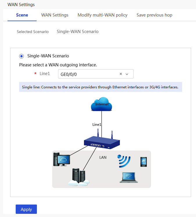
1. From the navigation pane, select Network > WAN Settings.
2. On the Scene tab, select the single-WAN scenario.
3. From the Line1 list, select WAN0 (GE0/0/0).
4. Click Apply.
Figure 2 Scene
5. Click the WAN Settings tab.
6. Click the Edit icon in the Actions column for interface WAN0.
7. From the Connection Mode list, select Fixed IP.
8. In the IP Address field, enter 20.1.1.2.
9. In the Subnet Mask field, enter 255.255.255.0.
10. In the Gateway field, enter 20.1.1.254.
11. In the DNS1 and DNS2 fields, enter the IP addresses of the primary and secondary DNS servers (114.114.114.114 and 8.8.8.8).
12. From the NAT list, select Enable.
13. Use the default settings for the other parameters, and then click Apply.
Figure 3 Connecting interface WAN0 to the Internet

Configuring the virtual server (port mapping)
|
|
NOTE: In this example, only the server's Web service port is mapped. Select the user-defined ports option for the global port number field, and configure the start and end port numbers to be consistent. As a best practice, enter a port number of 10000 or higher. |
1. From the navigation pane, select Network > NAT.
2. Click Add.
3. From the Interface list, select WAN0 (GE0/0/0).
4. In the Protocol Type field, select TCP.
5. In the Global IP address field, select Current IP address.
6. From the Global port number list, select User-defined ports, and enter 8080 in both the Start port number and End port number fields.
7. In the Local IP address field, enter 192.168. 1.2.
8. In the Local port number field, enter 80.
9. Click Apply.
Figure 4 Adding a NAT port mapping

Verifying the configuration
On the PC of a traveling employee, enter http://20.1.1.2:8080 in the browser to access the Web page of the internal OA server in the company. Verify that the configuration succeeds.
