- Released At: 08-05-2025
- Page Views:
- Downloads:
- Table of Contents
- Related Documents
-
WAAS Technology White Paper
Copyright © 2024 New H3C Technologies Co., Ltd. All rights reserved.
No part of this manual may be reproduced or transmitted in any form or by any means without prior written consent of New H3C Technologies Co., Ltd.
Except for the trademarks of New H3C Technologies Co., Ltd., any trademarks that may be mentioned in this document are the property of their respective owners.
The content in this article is general technical information. Some information may not be applicable to the product you purchased.
Contents
Congestion algorithm optimization
Packet duplication implementation
Introduction to packet duplication
Basic principle of packet duplication
Packet duplication processing flow
Unidirectional LZ compression for TCP/UDP
Scenario of packet duplication
Overview
Technical background
With the rapid integration of IT infrastructure leading to relatively centralized data and the trend of employees working remotely on a global scale, more and more company application systems need to be accessed via wide area network (WAN) transmission. A good communication environment between the WAN branches and the headquarters' data center, along with user experience, cannot only effectively enhance the work efficiency of the office but also provide assurance for diversified customer services at the WAN branches.
Currently, the types and characteristics of services carried by the wide area network (WAN) are shown in Table 1.
Table 1 Types and characteristics of WAN services
|
Business type |
Business characteristics |
|
The business operations of the enterprise production application. |
Core applications that support the normal operation of enterprise branches, such as enterprise group OA office systems, the company's financial systems, order management systems, ERP enterprise resource systems, CRM customer relations management (CRM) systems, etc., often transmit their data in small datagram packets. A single application often requires multiple interactions between the branch client and the headquarters server, to perform behaviors such as querying application databases and submitting data inputs. The network delay has the most direct impact on the experience of such types of applications. |
|
Application for data transmission of large files. |
Data transmission is primarily unidirectional, mainly transmitting from the corporate headquarters data center to remote branches. The content of the transmission in the link is predominately large data packets, with a single transmission capacity reaching tens of megabytes or even several gigabytes. In this scenario, the bandwidth of the wide area network (WAN) link directly affects the result of file transmission. Moreover, large-capacity, long-term, and multifrequency data downloading will severely impact the bandwidth utilization of the WAN. |
|
Unified communication services primarily based on instant messages such as voice, video frequency (VF), QQ, and WeChat for Business. |
Common service types include VoIP conference calls, video conferences, instant messaging tools like QQ/MSN, and network conferences. This class of data transmission is predominantly interactive, with packet length being uncertain and a mix of large and small packets present. It places high demands on network bandwidth and Round-Trip Time (RTT) delay. |
|
Internet class business applications. |
The priority level of this type of business is relatively low, and it is acceptable even if the bandwidth is insufficient OR the link delay is relatively large. The most important thing for this type of business is to prevent a large amount of unrelated work from abusing the bandwidth. |
Due to the issues like high application latency leading to poor user experience, insufficient bandwidth utilization resulting in high deployment and maintenance costs, and inability to guarantee the quality of bandwidth for critical services, wide area network (WAN) optimization technology emerged.
WAAS tech system
WAAS (Wide Area Application Services) is a technology that provides optimization for wide area network (WAN) link traffic. Devices supporting WAAS technology can improve the drawbacks of high latency and low bandwidth in WAN links through the configuration of optimization actions.
WAAS includes TCP optimization and UDP optimization.
TCP optimization
TCP optimization can accelerate file transmission, reduce network latency, minimize the packet loss rate, and enhance the performance of TCP-based applications on the wide area network (WAN).
The TCP optimization supports the following optimization techniques:
· TFO (Transport Flow Optimization) is the optimization of the transport layer stream.
· DRE (Data Redundancy Elimination)
· LZ (Lempel-Ziv compression, also known as LZ compression)
· Packet duplication.
UDP optimization
UDP optimization can reduce packet loss rate and decrease the usage of network bandwidth.
The UDP optimization supports the following technical optimization methods:
· FEC (Forward Error Correction).
· LZ compression.
· Packet duplication (supported only when the application layer protocol is RTP).
WAAS optimization process
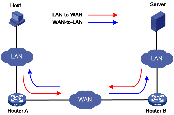
As shown in Figure 1, WAAS optimization involves traffic in two directions: from LAN to WAN and from WAN to LAN. Taking TCP optimization as an example, the overall optimization process is as follows:
1. During the handshake process to establish a TCP connection, Router A and Router B negotiate the intersection of their TFO optimization capabilities. They then use the optimization capabilities supported by both parties to perform TFO optimization processing on the data flow.
2. For traffic in the LAN-to-WAN direction, the device compresses packets and then transmits the compressed packets to the WAN network. The currently supported compression methods are DRE and LZ.
3. For traffic in the WAN-to-LAN direction, the device performs decompression processing on the packets, and transmits the decompressed packets to the LAN network.
Figure 1 WAAS application scenario
WAAS implementation
TFO implementation
Introduction to TFO
TFO refers to Transport Layer Flow Optimization technology. Without changing the source, destination IP address and port number of the TCP traffic, it transparently proxies the TCP connection at both ends of the Wide Area Network (WAN) link, and optimizes the TCP traffic on the WAN link.
The optimization methods for TFO include:
· Slow start optimization.
· Increased buffering.
· Congestion algorithm optimization.
· Selective acknowledgement.
Slow start optimization
The initial congestion window size for TCP slow start is one TCP segment. During slow start, TCP doubles the congestion window size for each received ACK that acknowledges new data. In this manner, the congestion window will reach an appropriate value by examining the congestion status. In a WAN environment, the congestion window takes a long time to reach an appropriate size because of high delay.
Slow start optimization shortens the slow start process by increasing the initial congestion window size.
Increased buffering
TCP has a maximum buffer size of 64 KB. After the sender sends 64 KB data, it must wait for an ACK from the receiver before continuing to send data. This mechanism wastes bandwidth on a WAN link.
Increased buffering increases the TCP buffer size to a maximum of 16384 KB. This improves link efficiency.
Congestion algorithm optimization
TCP uses the congestion window to control congestion. The window size indicates the size of data that can be sent out before an ACK is received. The window size changes with the congestion status. The greater the window size, the faster the data rate. A higher data rate more likely causes congestion. The smaller the window size, the lower the data rate. A lower data rate causes low link efficiency.
Congestion algorithm optimization achieves a trade-off between the data rate and congestion by selecting the optimum window size.
Comware supports several mainstream TCP congestion control algorithms: Reno, BIC, BBRv1, and BBRv2. The key technologies and recommended scenarios for each algorithm are shown in Table 2. For a detailed introduction to congestion control algorithms, please refer to the "Technology White Paper on TCP Congestion Control Algorithm Optimization in Wide Area Network (WAN)".
Table 2 A comparison of Reno, BIC, and BBR congestion control algorithms
|
Algorithm |
Critical Technology |
Scenarios |
|
Reno |
· Triggering congestion control based on packet loss can easily lead to misjudgments as it does not distinguish between whether the packet loss is due to errors or actual network congestion. · When packet loss is detected, the congestion window (CWND) is halved. · The congestion window (CWND) undergoes linear growth through sniffering. Each time an RTT passes, the CWND is increased by 1. |
In scenarios requiring low packet loss rate, low bandwidth and low latency requirements. |
|
BIC |
· Using packet loss as a trigger condition for congestion control, without distinguishing whether the reason for the packet loss is error or real network congestion, can easily lead to misjudgment. · When packet loss is detected, the congestion window (CWND) is halved. · The congestion window (CWND) is probed using the binary search method and the multiplicative increase method. |
In scenarios requiring low packet loss rate, high bandwidth, and low latency demands. |
|
BBRv1 |
Do not use packet loss as the trigger condition for congestion control. Based on the periodical sniffer of latency and bandwidth, calculate the congestion window (CWND) and transmit rate. Transmit the packets steadily. |
There exists a scenario with a certain packet loss rate, high bandwidth, high demands for time delay, where the BBR algorithm is used alone. |
|
BBRv2 |
Compared to BBRv1: · In the Startup state, BBRv2 will exit this state once packet loss is detected, in order to avoid more severe packet loss. · The trigger condition for BBRv2 to enter the RTprop state has been reduced from 10 seconds to 2.5 seconds (if RTprop is not updated for a continuous 2.5 seconds, then BBRv2 immediately enters the ProbeRTT state to sniff out the new RTprop), allowing timely adjustment of the congestion window CWND, in order to quickly respond to network changes. · After entering the ProbeRTT state, BBRv2 reduces the congestion window (CWND) to 0.5*BtlBw*RTprop (BBRv1 reduces the CWND to 4), in order to minimize the bandwidth fluctuations caused by entering the ProbeRTT state. |
There exists a scenario with a certain packet loss rate, high bandwidth, high latency requirements, and various algorithms coexisting. |
Selective acknowledgement
TCP uses a cumulative acknowledgement scheme. This scheme forces the sender to either wait a roundtrip time to know each lost packet, or to unnecessarily retransmit segments that have been correctly received. When multiple nonconsecutive segments are lost, this scheme reduces overall TCP throughput.
Selective acknowledgement (SACK) allows the receiver to inform the sender of all segments that have arrived successfully. The sender retransmits only the segments that have been lost.
DRE implementation
DRE Introduction
DRE is a data redundancy elimination technology that improves data transmission speed by reducing the amount of data transmitted over wide area network (WAN) links. It achieves this by using a bidirectional database to save previously detected TCP traffic and replacing duplicate data blocks with minimal-bandwidth indexes.
|
|
NOTE: In the compression mechanism, data blocks are non-overlapping MAC protocol data units (MPDU) allocated by WAAS for transmitting compressed data, used for detecting whether the content to be transmitted is duplicated. For duplicate data blocks, WAAS replaces them with dictionary indexes for transmission. |
Basic principles of DRE
The basic principle of DRE is as follows:
1. Before transmitting a data block, the sender first searches the DRE dictionary. If the dictionary entry for this data block is found, it is assumed that this data block has been previously transmitted, and it is referred to as a duplicate data block.
2. The transmitter replaces repeated data blocks with dictionary index for transmission on the wide area network (WAN) link, a process known as DRE compression.
3. The receiving end restores it to repeated data blocks by identifying the dictionary index, a process known as DRE decompression.
DRE processing workflow
Figure 2 Principle of DRE Compaction Diagram
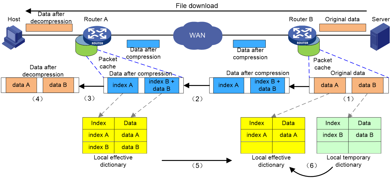
As illustrated in Figure 2, using the example of a host downloading a file from a server, the process of data transmission optimized with DRE is as follows:
1. The transparency proxy module of Router B receives and caches the original TCP data blocks, and then transmits them to the DRE module. The DRE module uses a slider detection technique to chunk and inspect the data, first dividing the data to be transmitted into non-overlapping data blocks, such as data A and data B, then checks whether they are repeated data blocks.
¡ If it is a duplicate data block, such as data A, replace the block with its corresponding dictionary index A and generate an MD5 digest based on the block. Then, transmit the dictionary index and MD5 digest information.
¡ If it's not a duplicate data block, such as data B, generate a corresponding dictionary index, index B, for it. Add this index and data block to the local temporary dictionary. Then, create an MD5 digest based on this data block, and transfer the data block, its corresponding dictionary index, and MD5 digest information.
2. Router B transmits the compacted data to Router A.
3. Router A restores the raw data based on the received data to obtain the corresponding original data.
¡ If the received data is a dictionary index, query the data dictionary based on this index to retrieve the corresponding repeated data block.
¡ If the received data is an index and data block, create a new dictionary entry based on the received data and add it to the local data dictionary.
4. Router A transmits the uncompressed data to the LAN side host.
5. Router A sends ACK/SACK information to Router B to validate the received data.
6. After receiving the validation information, Router B adds the non-duplicate data it confirms receipt of to its local active dictionary, and retransmits the data that was not received.
Router A and Router B have synchronous local effective dictionaries. Both devices pass through caching the local effective dictionaries, thus compressing and decompressing the packets, reducing the consumption of bandwidth.
LZ implementation
Introduction to LZ
LZ compression is a type of lossless data compression technology, including a series of compression algorithms. Currently, H3C employs LZ compression algorithm prioritizing processing speed while ensuring compression rate, so that LZ compression can meet the performance requirement of message forwarding.
The difference between LZ and DRE compression is that LZ doesn't require both compression and decompression to synchronously save the data dictionary. Instead, it uses a self-built dictionary method for compression replacement, with its compression dictionary embedded in the compression result. For instance, when the raw data 'data1' is compressed into 'sequence1', there's no need to look up the local dictionary. The raw data is divided into different subsequences. When encountering a repeated subsequence like 'bcde', it uses sequence offset and match length [5 ,4] for replacement to achieve the purpose of compression.
Basic principle of LZ
The basic principle of LZ compression is to represent sequences of strings that have appeared in historical data with a special format or special small sequence. Because these special formats or sequences are usually smaller than the original string sequence, LZ can achieve a compression effect.
LZ processing process
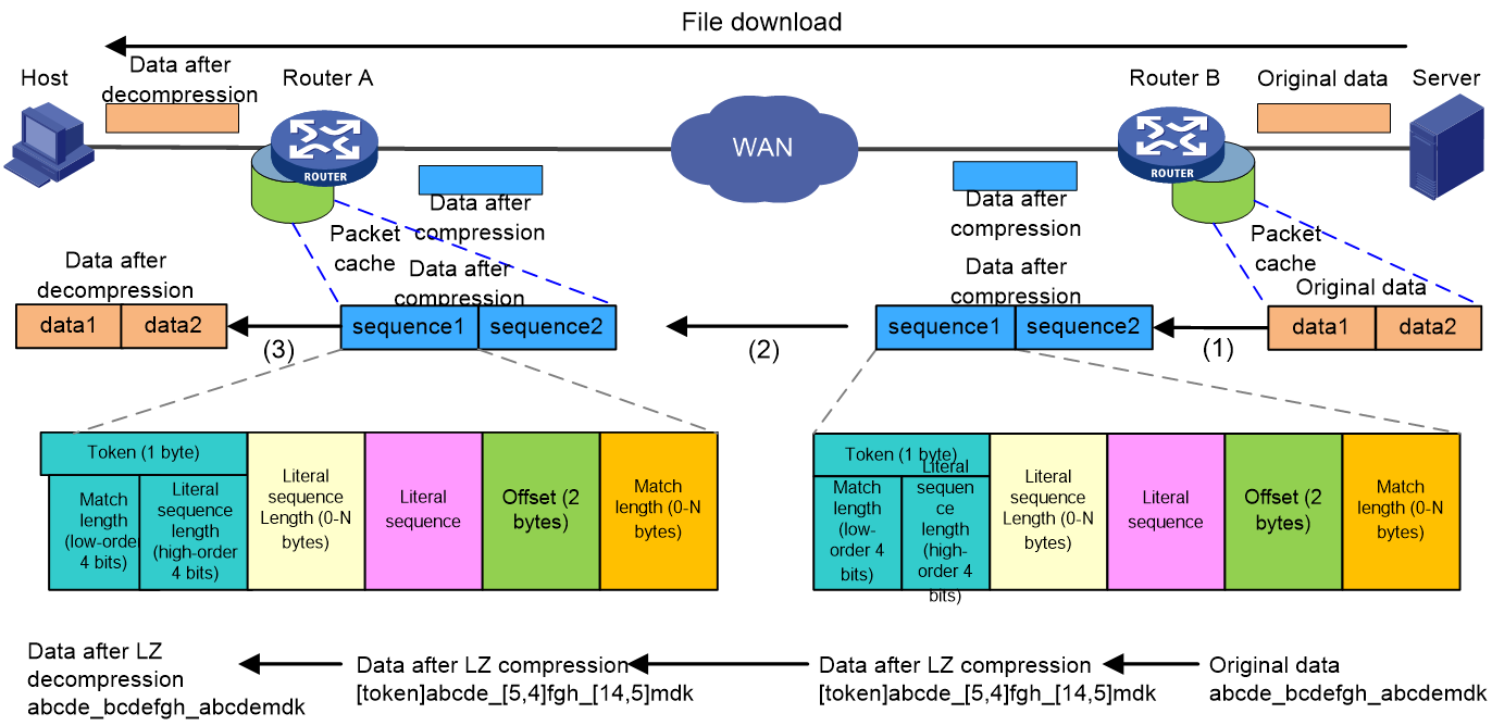
As shown in Figure 3, using the example of a host downloading a file from a server, the data transmission process is as follows when LZ optimization is used:
1. After receiving and caching the raw datagram, Router B applies LZ compression to it. For example, the raw data for data1 is abcde_bcdefgh_abcdemdk, which after compression, is converted into sequence1 data as [token]abcde_[5,4]fgh_[14,5]mdk. This includes:
¡ The token, which marks the beginning of each sequence, comprises one byte. This token is divided into two 4-bit fields: the match length field indicates the number of characters in the match sequence, while the literal sequence length field denotes the number of characters in the literal sequence.
¡ Literal sequence length: 0 to N bytes, representing the number of characters in the literal sequence, stored in two scenarios. If the character count is less than or equal to 15, simply store the value in the high 4 bits of the token; if the value is greater than 15, store 15 in the high 4 bits of the token, and the difference between the value and 15 in the following bytes of the token.
¡ Literal sequence: This refers to sequences and their sub-sequences that are believed to have not appeared in previous historical data. They are saved in their original form, and they will be completely copied when decompressed.
¡ Matched sequence: A previously appeared sequence represented by an offset and match length.
¡ Offset: 2 bytes, indicating the difference in character count between the starting character of the sequence to be decompressed and the starting character of the already appeared literal sequence.
¡ Match Length: 0 to N bytes, which indicates the number of characters in the match sequence, similar to the literal sequence length, it is also stored in two parts. If the number of characters is less than or equal to 15, only need to store the value in the lower 4 bits of the token; if the value is greater than 15, then store 15 in the lower 4 bits of the token and store the difference between the value and 15 in the bytes following the offset.
2. Router B transmits the compacted sequence messages to the receiving end, Router A.
3. Router A receives the compressed message, decompresses it using the LZ algorithm to obtain the raw data, and transmits this raw data to the host on the LAN side.
FEC implementation
Introduction to the concepts
Redundancy packets
The FEC sender encodes original packets and generates redundant packets. The header information of a redundant packet includes the number of original packets, the number of redundant packets, and sequence numbers. The FEC receiver decodes received data and recovers lost packets according to the received original packets and redundant packets.
FEC average ratio
The FEC average ratio is the packet loss ratio that can be toleranted without affecting normal communication. It determines the number of redundant packets generated for a group of original packets. The greater the FEC average ratio, the more the redundant packets generated. FEC average ratio must be greater than the actual packet loss ratio. As a best pratice, the configured FEC average ratio is larger than the actual packet loss ratio.
Block size
The block size is the maximum number of original packets that can be encoded at a time during FEC coding. During FEC optimization, when the number of original packets stored in the device's cache reaches the block size, the WAAS device begins to generate redundant packets, and transmits both the original packets and redundant packets.
Basic principle of FEC
The real-time packets (audio and video packets) transported over RTP on the Internet can experience common problems such as out-of-order packets, packet loss, and packet duplication.
FEC is a forward error correction technology.
1. The transmission end prepares the original packets for transmission, generates redundant packets based on the configured block size and FEC average ratio, and then sends the redundant packets appended behind the original packets to the receiving end. Redundant packets are not simply copies of the original packet. The info in the headers of redundant packets includes the number and sequence numbers of the original packets and redundant packets within the group.
2. Upon receiving the data packet, the receiver first checks for any lost packets. If any are found, it decodes the information using the redundant packet, restores the original data packet, and then transmits it to the intended destination.
FEC workflow
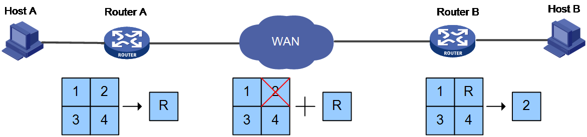
As shown in Figure 4, the workflow for FEC on packets is as follows:
1. Audio and video frequency (VF) data packet identification.
a. Call message processing: After Router A receives audio and video frequency call messages, it generates a session for the messages and sets up an Application Level Gateway (ALG) service tag for datagram identification.
b. Datagram Processing: Upon receiving a datagram, Router A carries out a match with the RTP class WAAS policy. If a policy match is found, it creates a fast forwarding entry for FEC and sets a fast forwarding service tag. If no policy is matched, it proceeds with normal forwarding.
2. The process of FEC coding.
a. Data Caching: Router A caches the RTP original packet.
b. FEC Coding Processing: When the original packet cached by Router A reaches the number of coding block packets OR the coding cache time reaches the timeout period, the device splits the cached original packets with serial numbers 1, 2, 3, 4 into a group. It then proceeds to perform FEC coding on them, generating one or more redundant packets R. Subsequently, it transmits both the cached original packets and the generated redundant packets.
3. The process of FEC decoding.
a. Data caching: Router B caches the received original packets 1, 3, 4 and the redundant packet R.
b. FEC decoding process: Within the decoding timeout period, if the sum of cached original packets and redundant packets is equal to or greater than the number of original packets in the group, the device will perform FEC decoding process on cached data packets 1, 3, 4, R, and restore the lost data packet 2. Then, data packets 1, 2, 3, 4 are transmitted, and the redundant packet R is discarded. If the caching period reaches the decoding timeout, the device will not perform FEC decoding on the cached data packets, but will transmit the original packets directly and discard the redundant packets.
FEC is categorized into two types based on the configuration of the average loss packet rate: A-FEC (Adaptive-FEC, autosensing FEC) and D-FEC (Determined-FEC, fixed FEC).
· A-FEC adjusts the average packet loss resistance according to real-time packet loss rate: The transmitting device includes the device address information in the redundant packet and announces it to the receiving end. The receiving end samples the packet loss rate of real-time data and periodically provides feedback to the transmitting end, thereby enabling the transmitting end to adjust the production of redundant packets, reduce the amount of data transmission in the wide area network (WAN) link, and increase data transmission speed.
· D-FEC employs a configured fixed average packet loss resistance rate. In environments with significant network fluctuations, D-FEC has more advantages.
Packet duplication implementation
Introduction to packet duplication
In wide area network (WAN) optimization scenarios, for services such as payment and emergency calls that require high reliability and have low traffic, if packet loss and significant delay occur during transmission, it could greatly impact the service, even leading to it going out of service.
At present, most local area networks (LAN) commonly use multiple WAN links to connect to the wide area network (WAN), and carry out load sharing among these multiple WAN links.
Package duplication is a redundancy correction technology that utilizes the advantage of multiple links to transmit the same message through two links. As long as the two links do not discard the message at the same time, the receiving end can integrate the same message information received on the two links into a complete stream. This effectively reduces, or even solves, issues such as out of service caused by packet loss on a single link.
|
|
NOTE: Currently, the packet duplication technology is only supported in a VXLAN networking environment. |
Basic principle of packet duplication
The basic principle of packet copying is as follows:
1. The transmitting end, for messages that match the packet duplication policy conditions, first queries whether an equivalent link exists on its WAN egress interface.
¡ If an equivalent link exists, the message will be duplicated onto the first equivalent link found, and then the message will be forwarded simultaneously from the WAN egress interface and that equivalent link found.
¡ If there is no equivalent link, there is no need to replicate. The packet can be directly forwarded from the route egress interface.
2. After the receiver receives the message, it integrates the messages received from two links through the message signature, namely, the received messages are processed for redundancy elimination and sequence preservation. The original business stream is reconstructed by synthesizing the messages from the two links, and then the original business stream is transmitted to the destination terminal.
Packet duplication processing flow
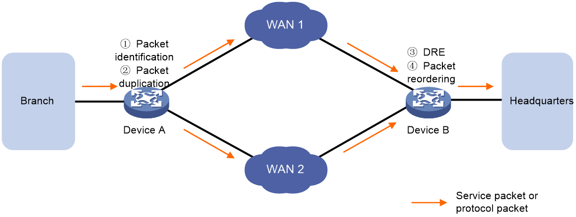
As shown in Figure 5, the processing flow of packet copying involves the following four steps:
1. Packet identification.
2. Packet duplication.
3. Packet redundancy elimination.
4. Maintaining packet order.
Figure 5 Packet duplication principle
Packet identification
· TCP packet processing: Device A analyzes the received packets. If all the following conditions are met, the packet is duplicated and forwarded. If any of these conditions are not met, it is forwarded normally.
¡ The packet type is TCP.
¡ Can match with the TCP optimization policy.
¡ The egress interface on WAN has an equivalent forwarding link.
· RTP packet processing: Device A analyzes the received packets. If the packet is a UDP packet, it determines whether it is a signaling packet.
¡ If it's a signaling message, then it's normally forwarded.
¡ If it isn't a signaling message and all the following conditions are met, then proceed with packet duplication and forwarding. If it isn't a signaling message and any of the following conditions are not met, then forward as usual.
- The session information corresponding to the message can be successfully obtained.
- The packet type is RTP.
- It can match the TCP optimization policy.
- There is an equivalent forwarding link present on the WAN egress interface.
Packet duplication
As shown in Figure 5, there are two equal cost links between Device A and Device B, namely Device A->WAN 1->Device B and Device A->WAN 2->Device B. Upon receiving the original packet, Device A identifies the packet and duplicates those that meet certain conditions. Following the rule of equal cost route selection, Device A identifies the egress interface for the original packet and transmits it. Afterwards, it selects the first equal cost link found in the routing table (excluding the link of the original packet's egress interface) to transmit the duplicate packet.
|
|
NOTE: The device will not perform packet duplication under the following circumstances: · The device memory is insufficient and has reached the memory alarm threshold. · The packet length exceeds the MTU of the transmission link. |
Packet redundancy elimination
After receiving packets from two links, Device B needs to process the received duplicate packets to ensure redundancy removal, retaining only one of each original and copied packet. The process of packet redundancy removal is as follows:
Device B receives messages from two links and searches for the message information in the redundancy link.
· If the same message information record does not exist in the redundancy chain, it is considered that the message is received for the first time. Add this message information to the redundancy chain and continue processing the message.
· If the same message info is found in the redundancy chain, determine whether the message is a retransmission or redundancy. Continue processing for retransmitted messages. For redundant messages, delete the corresponding message info from the redundancy chain and discard the redundant message.
|
|
NOTE: A redundancy chain is a buffer used to store packet information. If the device receives a packet whose information matches the packet information saved in the redundancy chain, it indicates that the received packet is a duplicate, and redundancy removal processing is required. |
Packet sequencing
The packet arrives at Device B via two links. Due to the different delays of the two links, the order of packet arrival may not coincide with the sequence number of the packet itself. Therefore, after Device B performs redundancy removal on the packet, it also needs to carry out sequence maintenance to ensure that the packets are transmitted in ascending order of sequence numbers as much as possible.
· If the packet is a fragmented packet, cache each arriving fragment until all fragments of the entire packet have arrived, then transmit (Tx). If the entire packet has not arrived when the fragmentation age timeout is reached, then transmit (Tx) the cached fragmented packets.
· If the packet is a non-fragmented packet, it is necessary to determine whether the sequence number of the current packet is the expected sequence number for the local interface to receive.
¡ If the sequence number of this message is the expected number or less, transmit it and update the expected number, then traverse through the sequence-keeping buffer chain. If there is a message in the sequence-keeping buffer chain with the expected sequence number, transmit that message and update the expected number again. Continue in this manner until all messages with the expected sequence number stored in the sequence-keeping buffer chain have been transmitted.
¡ If the sequence number of this packet is greater than the expected sequence number, then add this packet to the order-preserving caching chain.
· Regardless of whether the interface receives a message or not, it will monitor the sequence preservation cache chain, transmit the messages that have aged beyond the timeout in this chain, and update the expected sequence number.
|
|
NOTE: The ordered caching chain is a buffer that stores packets, aiming to ensure that packets are transmitted to the next hop in order of sequence number as much as possible. If the sequence number of the received packet is greater than that of the expected packet, meaning the packet arrives early, the interface temporarily stores this packet in the ordered caching chain. This allows for these packets to be transmitted after the expected packet is sent. In order to prevent prolonged wait times for anticipated messages leading to a decline in communication, an in-order cache chain supports an aging mechanism that times out. This means that regardless of whether the anticipated message arrives or not, each message in the in-order cache chain will be transmitted after a fixed age. In order to address sudden packet bursts and excessive memory usage by multiple packets in a sequence-preserving cache chain, a capacity limit is set. When the number of packets in the sequence-preserving cache chain reaches the maximum capacity, even the oldest packet that has not aged is transmitted to allow new packets to enter the sequence-preserving cache chain. For instance, if the interface expects to receive a message with a sequence number of 3 but actually receives a message with a sequence number of 4, the message with sequence number 4 will be placed in the sequence-reserving cache chain, waiting for the message with sequence number 3. · If the sequence number of the next incoming packet is 3, transmit the packet with the sequence number 3 and update the expected sequence number to 4. Then, traverse the order-preserving buffer chain, transmit the packet with sequence number 4 and update the expected sequence number to 5. · If the next arriving message has a sequence number of 5, it's placed into the sequence-preserving cache chain, with the expected sequence number remaining at 3. If the following message has a sequence number of 3, transmit the message with sequence number 3 and update the expected sequence number to 4. Then, traverse the sequence-preserving cache chain, transmit the message with sequence number 4, and update the expected sequence number to 5. Continue to traverse the chain, transmit the message with sequence number 5, and update the expected sequence number to 6. This way, the messages with sequence numbers 3, 4, and 5 can be transmitted in order. · If the packet with sequence number 4 in the cache chain has reached its age timeout, but the packet with the expected sequence number 3 has not been received, then transmit the packet with sequence number 4 and update the expected sequence number to 5. |
Typical applications
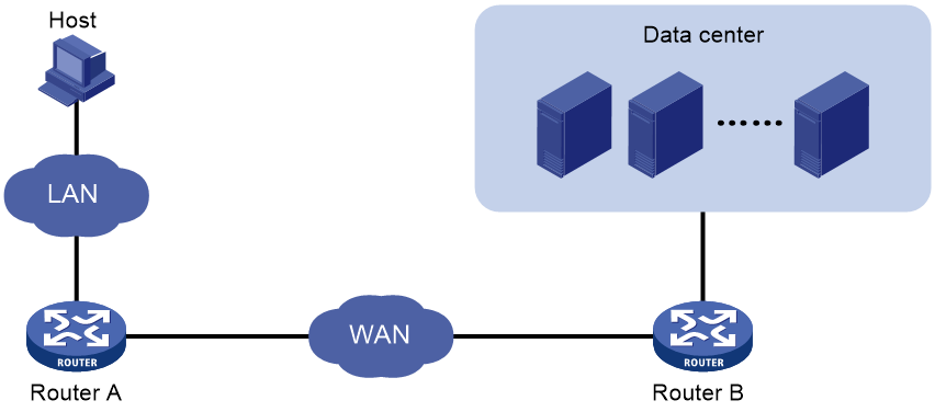
TFO+DRE optimization scenario
As shown in Figure 6, the data center provides video and game services, with users accessing the data center via the wide area network (WAN), resulting in high access and data volumes. By deploying the TCP optimization techniques TFO+DRE on WAN access devices, Router A and Router B, it is possible to effectively reduce the packet loss rate of the WAN and improve the drawbacks of high latency and low bandwidth on WAN links.
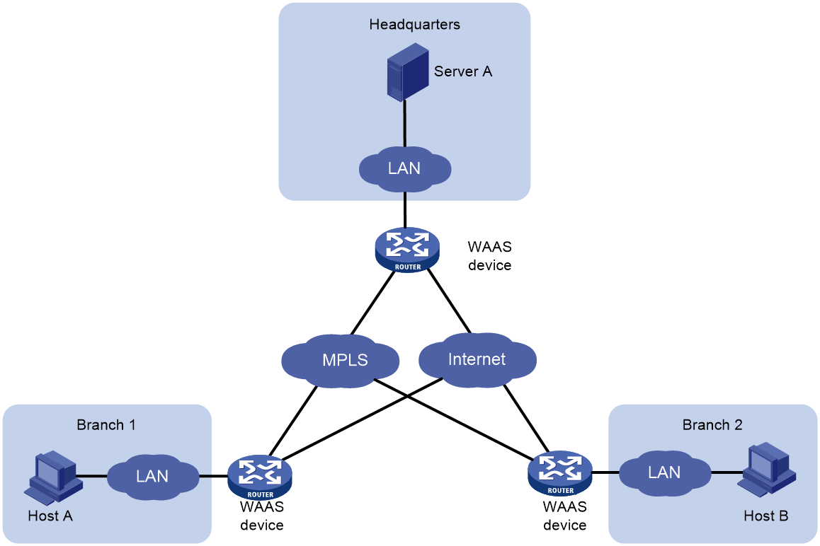
Unidirectional LZ compression for TCP/UDP
Data transmission between the corporate headquarters' data center and remote branches, in most cases, is one-directional from the data center to remote branches, predominantly with large data packets. The single transmission capacity can reach tens of megabytes or even multiple gigabytes. For instance, remote branches often review files, download software, access company websites/databases at the corporate headquarters' data center. Under such circumstances, the bandwidth of the wide area network (WAN) link will directly affect the users' transmission results. Heavy capacity, long duration, and multifrequency data downloading will significantly impact the bandwidth utilization of the WAN. WAAS devices can save bandwidth by configuring TCP/UDP single-direction LZ compression function.
As shown in Figure 7, after enabling the TCP/UDP unidirectional LZ compression function on the WAAS device at the transmitting end, it will reduce the bandwidth used for synchronous data transmission between the headquarters' data center and remote branches.
Figure 7 TCP/UDP unidirectional LZ compaction
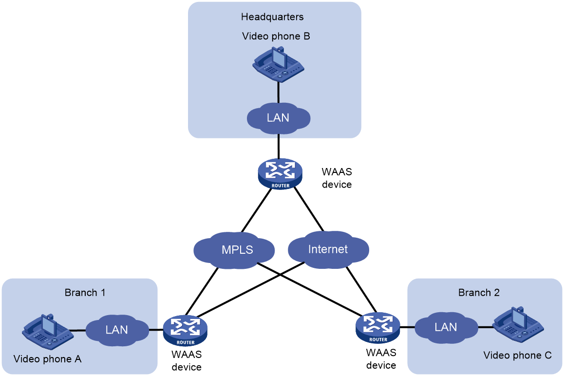
FEC optimization scenario
The data flow of voice and video frequency (VF) imposes higher demands on the network's bandwidth and Round Trip Time (RTT).
As shown in Figure 8, enabling the Forward Error Correction (FEC) optimization function on the WAAS device ensures smooth, glitch-free operation of crucial video applications even when there is a 20% packet loss. It provides strong support for the smooth conduct of audio and video conferences.
Figure 8 Forward Error Correction (FEC)
Scenario of packet duplication
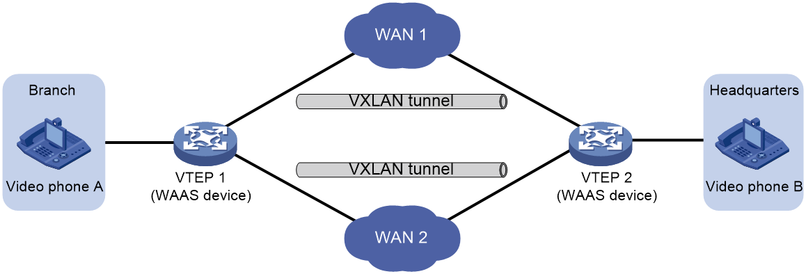
As shown in Figure 9, a company's branch office is connected to the headquarters through dual WAN link across VXLAN network. For business messages with high reliability requirements and small traffic (such as payment, emergency call, etc.), the dual WAN link networking feature is utilized. By deploying the packet duplication function of WAAS, it effectively reduces and even solves the packet loss and disorder problems in single links during WAN link transmission, ensuring high availability for the business operations.
Related documentation
· RFC 1323: TCP Extensions for High Performance
· RFC 2582: The NewReno Modification to TCP's Fast Recovery Algorithm
· RFC 2733: An RTP Payload Format for Generic Forward Error Correction
