- Released At: 18-12-2024
- Page Views:
- Downloads:
- Table of Contents
- Related Documents
-
SRv6 OAM Technology White Paper
Copyright © 2024 New H3C Technologies Co., Ltd. All rights reserved.
No part of this manual may be reproduced or transmitted in any form or by any means without prior written consent of New H3C Technologies Co., Ltd.
Except for the trademarks of New H3C Technologies Co., Ltd., any trademarks that may be mentioned in this document are the property of their respective owners.
The content in this article consists of generic technical information, some of which may not be applicable to the product that you purchased.
Contents
SRv6 OAM
Background
SRv6 and SRv6 TE policies are used as tunneling technologies for service traffic. Only the controller or source node can sense the data forwarding paths. Intermediate nodes neither maintain nor sense these forwarding paths. When data fails to pass through SRv6 BE or SRv6 TE policy due to an anomaly on some intermediate node, the controller or source node cannot detect and locate the fault. Therefore, we need a maintenance method for detecting and locating faults along the forwarding path. SRv6 Operations, Administration, and Maintenance (OAM) can meet this requirement.
SRv6 OAM supports the following detection methods:
· SRv6 SID-based ping and SRv6 TE policy-based ping—Detect the network connectivity and host reachability.
· SRv6 SID-based tracert and SRv6 TE policy-based tracert—Detect network connectivity and locates network problems.
SRv6 OAM protocol extensions
OAM O-flag
Figure 1 O-flag in SRH Flags field
![]()
As shown in Figure 1, the O-flag is located in the Flags field of the SRH, indicating that an SRv6 node need to execute OAM processing. If the O-flag is set in the packet, every endpoint in the SRv6 network needs to duplicate the packet, add a timestamp, and submit the packet with the timestamp to the control plane for processing. In SRv6 OAM, to request all SRv6 nodes on the path to respond to OAM packets, make sure the O-flag is set for the OAM packets at the source node.
Based on the O-flag setting, segment-by-segment OAM detection can be achieved. For example, segment-by-segment SRv6 SID-based ping and overlay SRv6 SID-based tracert can be implemented by setting the O-flag.
End.OP SID
|
|
NOTE: In the ping/tracert scenario of SRv6 SID and SRv6 TE policy, the connectivity of the SRv6 path can be checked through the packet, regardless of whether the End.OP SID is carried in the packet or not. |
An End.OP SID is an SRv6 SID of OAM type used in SRv6 SID/SRv6 TE policy-based ping/tracert operations.
The End.OP SID is used to identify OAM detection packets, allowing the destination node to identify the packets and carry out processing. Based on the End.OP SID, end-to-end OAM detection can be achieved. For example, end-to-end SRv6 SID-based ping and hop-by-hop SRv6 SID-based tracert can be realized through the use of End.OP SID.
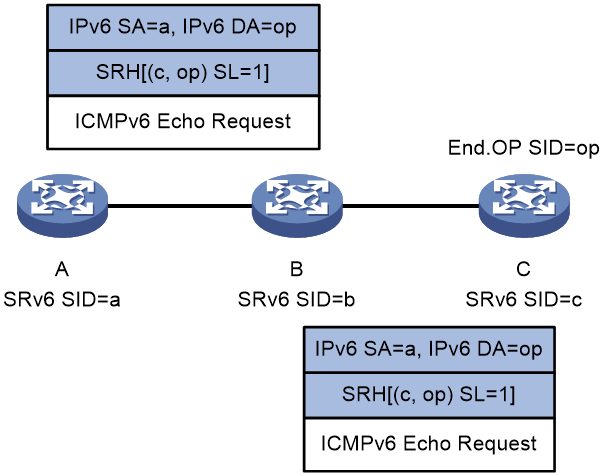
The forwarding action corresponding to End.OP SID is as follows: If the device receives a packet with the destination address as End.OP SID, it checks the next SRv6 SID. If the next SRv6 SID is the local SRv6 SID, it replies with a response packet. If not, it discards the packet. Take SRv6 SID-based ping as an example. As shown in Figure 2, in order to ping Device C, Device A constructs an ICMPv6 echo request by adding the End.OP SID of Device C to the SRH header in the request. Upon receiving the request and finding that request is destined for the local End.OP SID, Device C further checks whether SRv6 SID c is the local SRv6 SID. If it is the local SRv6 SID, Device C sends an ICMPv6 echo reply; if not, Device C discards the ICMPv6 echo request.
Figure 2 End.OP SID application
SRv6 SID-based ping
SRv6 OAM supports segment-by-segment ping and end-to-end ping.
Segment-by-segment ping
Use segment-by-segment ping to detect connectivity of all SRv6 nodes in the SRv6 path. All SRv6 nodes will send an ICMPv6 echo reply to the source node.
Figure 3 Segment-by-segment ping

Figure 3 shows the segment-by-segment ping process as follows:
1. Device A initiates a ping to Device D, with the SRv6 SIDs of Device B and Device D specified. It constructs an ICMPv6 echo request encapsulated with an SRH and then sends the request.
2. Upon receiving the ICMPv6 echo request, the intermediate node performs relevant operations depending on whether it is SRv6 capable:
¡ On an SRv6 capable node (such as Device B):
The node sends an ICMPv6 echo reply to Device A, and forwards the ICMPv6 echo request based on the SRH if the following conditions exist:
- The packet destination IPv6 address is the local SRv6 SID.
- The O-flag is set in the packet SRH Flags field.
¡ On an SRv6 incapable node (such as Device C):
The node forwards the ICMPv6 echo request according to routing table lookup without returning an ICMPv6 echo reply to Device A.
3. Upon receiving the ICMPv6 echo request with O-flag set and SL=0 in the SRH, Device D verifies the packet destination IPv6 address.
¡ If the IPv6 address is the local SRv6 SID, the verification succeeds, and Device D sends an ICMPv6 echo reply to Device A.
¡ If the IPv6 address is not the local SRv6 SID, the verification fails, and Device D discards the ICMPv6 echo request.
4. Device A determines whether the destination node is reachable based on reception of the ICMPv6 echo reply:
¡ If the ICMPv6 echo reply is received before the specified timeout timer expires, the destination node is reachable.
¡ If no ICMPv6 echo reply is received when the specified timeout timer expires, the destination node is unreachable.
End-to-end ping
Use end-to-end ping to detect connectivity of the destination node in the SRv6 path. Only the destination node sends an ICMPv6 echo reply to the source node.
An SRv6 SID-based end-to-end ping can be performed regardless of whether the End.OP SID is specified. This section describes such a ping operation without the End.OP SID specified.

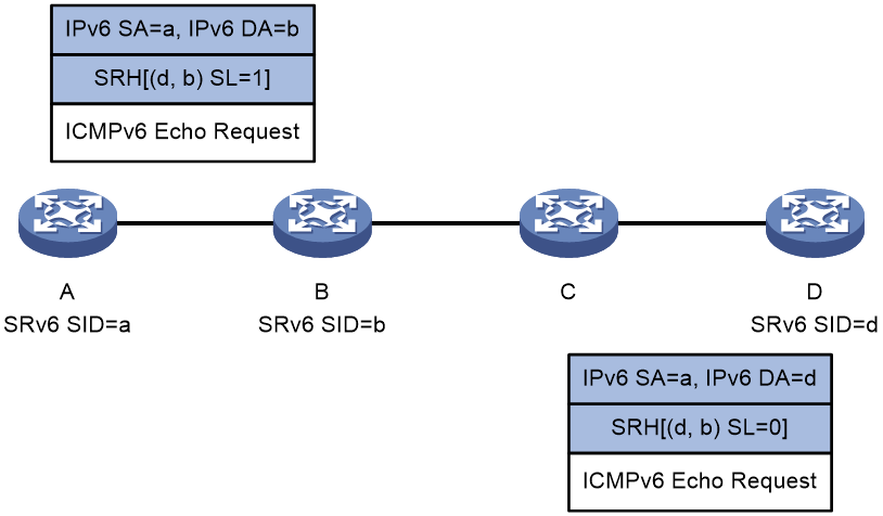
Figure 4 shows the end-to-end ping process as follows:
1. Device A initiates a ping to Device D, with the SRv6 SIDs of Device B and Device D specified. It constructs an ICMPv6 echo request encapsulated with an SRH and then sends the request.
2. Upon receiving the ICMPv6 echo request, the intermediate node performs relevant operations depending on whether it is SRv6 capable:
¡ On an SRv6 capable node (such as Device B):
The node forwards the ICMPv6 echo request based on the SRH if the packet destination IPv6 address is the local SRv6 SID.
¡ On an SRv6 incapable node (such as Device C):
The node forwards the ICMPv6 echo request according to routing table lookup.
3. Upon receiving the ICMPv6 echo request with SL=0 in the SRH, Device D verifies the packet destination IPv6 address.
¡ If the IPv6 address is the local SRv6 SID, the verification succeeds, and Device D sends an ICMPv6 echo reply to Device A.
¡ If the IPv6 address is not the local SRv6 SID, the verification fails, and Device D discards the ICMPv6 echo request.
4. Device A determines whether the destination node is reachable based on reception of the ICMPv6 echo reply:
¡ If the ICMPv6 echo reply is received before the specified timeout timer expires, the destination node is reachable.
¡ If no ICMPv6 echo reply is received when the specified timeout timer expires, the destination node is unreachable..
SRv6 SID-based tracert
SRv6 OAM supports overlay tracert and hop-by-hop tracert.
Overlay tracert
Use overlay tracert to display information about only SRv6 nodes in the SRv6 path.
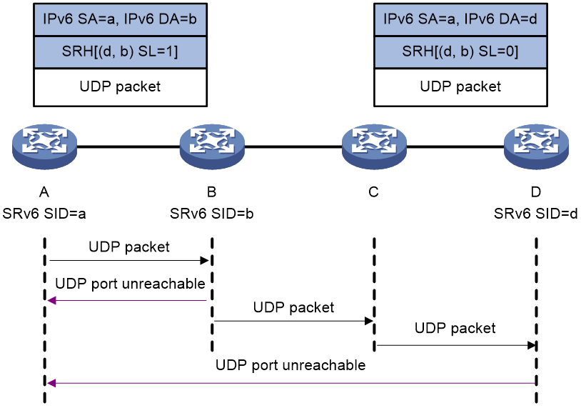
Figure 5 shows the overlay tracert process as follows:
1. Device A initiates a tracert to Device D, with the SRv6 SIDs of Device B and Device D specified. It constructs a UDP packet encapsulated with an SRH and then sends the UDP packet (the Hop Limit value is 64 in the IPv6 packet header).
Make sure you specify a destination UDP port that is not used by any applications on the destination node.
2. Upon receiving the UDP packet, the intermediate node performs relevant operations depending on whether it is SRv6 capable:
¡ On an SRv6 capable node (such as Device B):
The node sends an ICMPv6 port unreachable message to Device A, and then forwards the UDP packet based on the SRH if the following conditions exist:
- The packet destination IPv6 address is the local SRv6 SID.
- The O-flag is set in the packet SRH Flags field.
¡ On an SRv6 incapable node (such as Device C):
The node forwards the UDP packet according to routing table lookup without returning an ICMPv6 port unreachable message.
3. Upon receiving the UDP packet with O-flag set and SL=0 in the SRH, Device D verifies the packet destination IPv6 address.
¡ If the IPv6 address is the local SRv6 SID, the verification succeeds, and Device D sends an ICMPv6 port unreachable message to Device A.
¡ If the IPv6 address is not the local SRv6 SID, the verification fails, and Device D discards the UDP packet.
4. Device A determines whether the destination node is reachable based on reception of the ICMPv6 port unreachable message:
¡ If the ICMPv6 port unreachable message is received before the specified timeout timer expires, the destination node is reachable. The tracert result displays the SRv6 path from the source node to the destination node.
¡ If no ICMPv6 port unreachable message is received when the specified timeout timer expires, the destination node is unreachable. You can locate the faulty node based on the tracert result.
Hop-by-hop tracert
Use hop-by-hop tracert to display information about all nodes (whether they are SRv6 capable or not) in the SRv6 path.
An SRv6 SID-based hop-by-hop tracert can be performed regardless of whether the End.OP SID is specified. This section describes such a tracert operation without the End.OP SID specified.
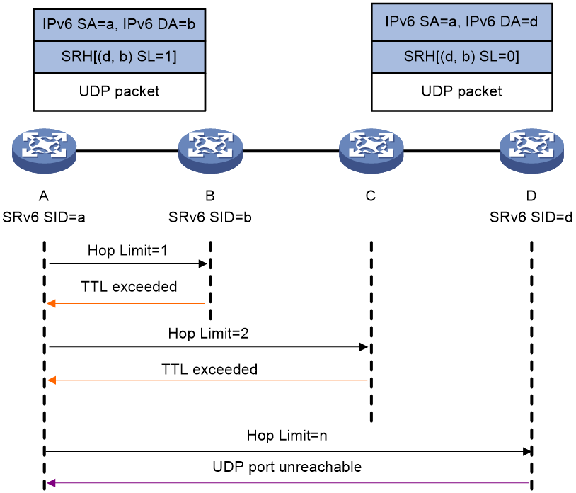
Figure 6 shows the hop-by-hop tracert process as follows:
1. Device A initiates a tracert to Device D, with the SRv6 SIDs of Device B and Device D specified. It constructs a UDP packet encapsulated with an SRH and then sends the UDP packet (the Hop Limit value is 1 in the IPv6 packet header).
Make sure you specify a destination UDP port that is not used by any applications on the destination node.
2. Upon receiving the UDP packet with the Hop Limit value in the IPv6 packet header being 0, the intermediate node sends an ICMPv6 timeout message to Device A.
3. Upon receiving the ICMPv6 timeout message, Device A sends another UDP packet by adding the Hop limit value by 1.
4. Upon receiving the UDP packet with the Hop Limit value in the IPv6 packet header not being 0, the intermediate node forwards the UDP packet as follows:
¡ On an SRv6 capable node (such as Device B):
The node forwards the UDP packet based on the SRH if the packet destination IPv6 address is the local SRv6 SID.
¡ On an SRv6 incapable node (such as Device C):
The node forwards the UDP packet according to routing table lookup.
5. Upon receiving the UDP packet (with Hop Limit 0 in the IPv6 packet header and SL=0 in the SRH), Device D verifies the packet destination IPv6 address.
¡ If the IPv6 address is the local SRv6 SID, the verification succeeds, and Device D sends an ICMPv6 port unreachable message to Device A.
¡ If the IPv6 address is not the local SRv6 SID, the verification fails, and Device D discards the UDP packet.
6. Device A determines whether the destination node is reachable based on reception of the ICMPv6 port unreachable message:
¡ If the ICMPv6 port unreachable message is received before the specified timeout timer expires, the destination node is reachable. The tracert result displays the SRv6 path from the source node to the destination node.
7. If no ICMPv6 port unreachable message is received when the specified timeout timer expires, the destination node is unreachable. You can locate the faulty node based on the tracert result.
SRv6 TE policy-based ping
Use SRv6 TE policy-based ping to detect reachability of each node in an SRv6 TE policy.
Figure 7 SRv6 TE policy-based ping
In Figure 7, the SID list of the SRv6 TE policy contains {b, d}. The SRv6 TE policy-based ping process is as follows:
1. Device A initiates a ping to Device D. It constructs an ICMPv6 echo request encapsulated with an SRH (that contains the SID list of the SRv6 TE policy) and then sends the request.
2. Upon receiving the ICMPv6 echo request, the intermediate node performs relevant operations depending on whether it is SRv6 capable:
¡ On an SRv6 capable node (such as Device B):
The node sends an ICMPv6 echo reply to Device A, and forwards the ICMPv6 echo request based on the SRH to Device C.
¡ On an SRv6 incapable node (such as Device C):
The node forwards the ICMPv6 echo request according to routing table lookup without returning an ICMPv6 echo reply to Device A.
3. Upon receiving the ICMPv6 echo request with SL=0 in the SRH, Device D verifies the packet destination IPv6 address.
¡ If the IPv6 address is the local SRv6 SID, the verification succeeds, and Device D sends an ICMPv6 echo reply to Device A.
¡ If the IPv6 address is not the local SRv6 SID, the verification fails, and Device D discards the ICMPv6 echo request.
4. Device A determines node reachability in the SRv6 TE policy based on reception of the ICMPv6 echo reply:
¡ If Device A receives the ICMPv6 echo reply from Device D before the specified timeout timer expires, all nodes in the SRv6 TE policy are reachable.
¡ If Device A does not receive the ICMPv6 echo reply from Device D when the specified timeout timer expires, the SRv6 TE policy contains unreachable nodes.
SRv6 TE policy-based tracert
Figure 8 SRv6 TE policy-based tracert

As shown in Figure 8, the SID list of the SRv6 TE policy contains {b, d}. The SRv6 TE policy-based tracert process is as follows:
1. Device A initiates a tracert to Device C. It constructs a UDP packet encapsulated with an SRH (that contains the SID list of the SRv6 TE policy) and then sends the UDP packet (the Hop Limit value is 1 in the IPv6 packet header).
Make sure you specify a destination UDP port that is not used by any applications on the destination node.
2. Upon receiving the UDP packet with the Hop Limit value in the IPv6 packet header being 0, the intermediate node sends an ICMPv6 timeout message to Device A.
3. Upon receiving the ICMPv6 timeout message, Device A sends another UDP packet by adding the Hop Limit value by 1.
4. Upon receiving the UDP packet with the Hop Limit value in the IPv6 packet header not being 0, the intermediate node forwards the UDP packet as follows:
¡ On an SRv6 capable node (such as Device B):
The node forwards the UDP packet based on the SRH if the packet destination IPv6 address is the local SRv6 SID.
¡ On an SRv6 incapable node (such as Device C):
The node forwards the UDP packet according to routing table lookup.
5. Upon receiving the UDP packet (with Hop Limit 0 in the IPv6 packet header and SL=0 in the SRH), Device D verifies the packet destination IPv6 address.
¡ If the IPv6 address is the local SRv6 SID, the verification succeeds, and Device D sends an ICMPv6 port unreachable message to Device A.
¡ If the IPv6 address is not the local SRv6 SID, the verification fails, and Device D discards the UDP packet.
6. Device A determines node reachability in the SRv6 TE policy based on reception of the ICMPv6 port unreachable message:
¡ If Device A receives the ICMPv6 port unreachable message from the destination node before the specified timeout timer expires, all nodes in the SRv6 TE policy are reachable. No faulty nodes exist.
¡ If Device A does not receive the ICMPv6 port unreachable message from the destination node when the specified timeout timer expires, the SRv6 TE policy contains unreachable nodes. You can locate the faulty node based on the tracert result.
Related documentation
draft-ietf-6man-spring-srv6-oam-05
