| Title | Size | Downloads |
|---|---|---|
| IPv6 Technology White Paper-6W100-book.pdf | 2.28 MB |
- Table of Contents
- Related Documents
-
| Title | Size | Download |
|---|---|---|
| book | 2.28 MB |
IPv6 Technology White Paper
Copyright © 2024 New H3C Technologies Co., Ltd. All rights reserved.
No part of this manual may be reproduced or transmitted in any form or by any means without prior written consent of New H3C Technologies Co., Ltd.
Except for the trademarks of New H3C Technologies Co., Ltd., any trademarks that may be mentioned in this document are the property of their respective owners.
This document provides generic technical information, some of which might not be applicable to your products.
The information in this document is subject to change without notice.
Contents
Hierarchical address structure
Format of IPv6 packets with extension headers
Enhanced neighbor discovery mechanism
Configuring IPv6 global unicast addresses
Stateless address autoconfiguration
Stateful address autoconfiguration (DHCPv6)
IPv6 upgrade and transformation plan
Deploying dual-stack on specific devices
Performing address translation at network boundaries
Comparison of upgrade and transformation plans
Comprehensive IPv6 deployment plan for campus networks
IPv6 transformation plan for financial networks
E-government external network IPv6+ applications
External link access failure prevention
Similarities and differences between IPv4 and IPv6 routing protocols
IPv6-based VXLAN and EVPN VXLAN
Overview
Internet Protocol Version 6 (IPv6) is the second generation of the standard network layer protocol, also known as IP Next Generation (IPng). IPv6 not only solves the problem of insufficient IPv4 address space, but also makes some improvements based on IPv4, such as introducing extension headers to increase the protocol scalability and providing built-in security to address network security issues.
IPv6 can provide wider connectivity for the Internet and IoT to realize the Internet of Everything, create digital infrastructure, and promote innovation in new applications and fields such as IoT, industrial Internet, and artificial intelligence. With the rapid development of emerging fields such as 5G and IoT, IPv6 has gained a broader space for development.
This document describes IPv6 advantages, extension of IPv6-based application protocols, and direction of IPv6 development (IPv6+), and provides common IPv6 deployment solutions to help users understand and deploy IPv6.
Benefits
Larger address space
IPv6 increases the IP address size from 32 bits to 128 bits. It can provide 3.4 x 1038 addresses to meet the requirements of hierarchical address assignment for both public and private networks.
Hierarchical address structure
IPv6 uses a hierarchical address structure to speed up route lookup, simplify address management, and reduce the IPv6 routing table size through route aggregation.
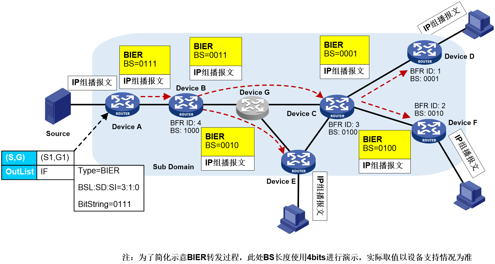
IPv6 addresses use a multi-layer hierarchy. After the address registry assigns an IPv6 address range, service providers and organizations can divide the address range in a hierarchical and more granular manner to control address distribution within their scope of management. As shown in Figure 1, an IPv6 address contains the following parts:
· Network prefix—Assigned by the China Internet Network Information Center (CNNIC) and ISP.
· Subnet ID—Organizations divide address ranges in a hierarchical manner as needed. For example, address ranges are first assigned to provinces and cities respectively based on geography, and then by serivce type.
· Interface ID—Host identified in the network.
Figure 1 IPv6 address structure
Simplified header format
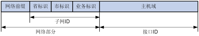
IPv6 removes several IPv4 header fields or moves them to the IPv6 extension headers to reduce the length of the basic IPv6 packet header. The basic IPv6 packet header has a fixed length of 40 bytes to simplify IPv6 packet handling and improve forwarding efficiency. Although the IPv6 address size is four times the IPv4 address size, the basic IPv6 packet header size is only twice the size of the option-less IPv4 packet header.
Figure 2 IPv4 packet header format and basic IPv6 packet header format
Flexible extension headers
IPv6 eliminates the Options field in the header and introduces optional extension headers to provide scalability and improve efficiency. The Options field in the IPv4 packet header contains a maximum of 40 bytes, whereas the IPv6 extension headers are restricted to the maximum size of IPv6 packets.
IPv6 extension header types
Table 1 displays extension headers supported by IPv6. Extension headers allow IPv6 to provide good scalability. According to service needs, you can define new IPv6 extension headers, or define new sub-extension headers for existing extension headers.
Table 1 IPv6 extension headers
|
Extension header name |
Type value |
Node for header processing |
Description |
|
Hop-by-Hop Options Header |
0 |
All nodes along the packet forwarding path |
Used for jumbo load alerts, router alerts, and Resource Reservation Protocol (RSVP). |
|
Routing Header |
43 |
Destination node and intermediate nodes through which packets must pass |
Used to specify intermediate nodes through which packets must pass. |
|
Fragment Header |
44 |
Destionation node |
When the length of an IPv6 packet exceeds the Path MTU (PMTU) of the packet forwarding path, the source node fragments the IPv6 packet and fills in fragment information in the fragment header. In an IPv6 network, only the source node can fragment packets. The intermediate nodes cannot perform packet fragmentation. NOTE: The PMTU is the minimum MTU on the packet forwarding path from the source node to the destination node. |
|
Encapsulating Security Payload Header (ESP Header) |
50 |
Destionation node |
Used to provide data encryption, data source authentication, data integrity verification, and anti-replay. |
|
Authentication Header |
51 |
Destionation node |
Used to provide data source authentication, data integrity verification, and anti-replay. It can protect packets from tampering but cannot prevent packet eavesdropping. It is suitable for transmitting non-confidential data. AH provides better authentication service than ESP. |
|
Destination Options Header |
60 |
Destination node and intermediate nodes specified in the routing header |
Used to carry information sent to the destination node and intermediate nodes specified in the routing header. For example, in mobility IPv6, the destination options header can be used to exchange registration information between mobile node and home agent. |
Format of IPv6 packets with extension headers
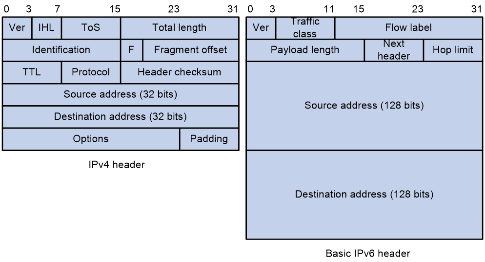
An IPv6 packet can carry zero, one or more extension headers. As shown in Figure 3, IPv6 uses the Next header field to identify the type of the next extension header. For example, a field value of 43 in the IPv6 basic packet header indicates that the next extension header is the routing header. A field value of 44 in the routing header indicates that the next extension header is the fragment header.
|
|
NOTE: The Next header field in the last extension header is used to identify the payload type. For example, a field value of 6 indicates that the payload is a TCP packet, and a field value of 17 indicates that the payload is a UDP packet. |
Figure 3 Format of IPv6 packets with extension headers
Enhanced neighbor discovery mechanism
The IPv6 neighbor discovery protocol uses a group of Internet Control Message Protocol for IPv6 (ICMPv6) messages to manage information exchange among neighboring nodes on the same link. The group of ICMPv6 messages replaces ARP messages, ICMPv4 router discovery messages, and ICMPv4 redirect messages and provides a series of other functions:
· Address resolution—Obtains the link layer addresses of neighbor nodes on the same link. It provides the same functions as IPv4 ARP.
· Neighbor reachability detection—Detects the state of a neighbor node after obtaining the neighbor's link layer address to verify if the neighbor is reachable.
· Duplicate address detection—Verifies if an IPv6 address has been used by another node after obtaining an IPv6 address. It provides similar functions to IPv4 gratutious ARP.
Built-in security
IPv4 itself does not provide security functions such as encryption and authentication, and must be used with security protocols (such as IPsec) or application protocols to provide security, which increases the complexity of application protocol design. IPv6 is designed with built-in security, which defines an ESP header and an authentication header to provide end-to-end security.
IPv6-based applications can directly inherit the security functions of the IPv6 protocol, providing a standard for solving network security issues and enhancing interoperability among different IPv6 applications.
IPv6-based protocol extension
Protocols (such as Telnet, SSH, and SNMP) used for device management, high reliability mechanisms (such as VRRP and M-LAG), and security protocols (such as 802.1X and port security) can support IPv6 without modification or with minor modifications. However, some application layer protocols, routing protocols, multicast protocols, and security protocols running in IPv4 networks require extensions to adapt to the IPv6 protocol. This section describes the extension methods of these protocols in the IPv6 network.
Configuring IPv6 global unicast addresses
Nodes can obtain global unicast IPv6 addresses through the following ways:
· Manual configuration.
· Stateless autoconfiguration: After obtaining the network prefix through the neighbor discovery protocol, nodes generate IPv6 unicast addresses automatically based on the obtained prefix.
· Stateful autoconfiguration: Nodes obtain IPv6 unicast addresses from DHCPv6 servers through the DHCPv6 protocol.
Table 2 displays scenarios suitable for different configuration methods of IPv6 global unicast addresses.
Table 2 Scenarios suitable for different configuration methods of IPv6 global unicast addresses
|
Address configuration method |
Advantages and disadvantages |
Applicable scenarios |
Prefix length requirement |
|
Manual configuration |
Advantages: Does not require protocol packet exchanges Disadvantages: Requires manual configuration and does not support dynamic adjustment |
Link local address or Loopback interface address |
No requirement (Custom supported) |
|
Stateless autoconfiguration |
Advantages: Extra server deployment is not required. Deployment is simple Disadvantages: Does not support precise control over IPv6 address allocation to nodes |
Strict control over terminal access behavior is not required, for example, IoT devices (video surveillance cameras or streetlights) |
Fixed to 64 bits |
|
Stateful autoconfiguration |
Advantages: Can perform precise control over IPv6 address allocation to nodes and record address allocation information Disadvantages: A DHCPv6 server must be deployed in the network, which is complicated |
Strict control over terminal access behavior is required, such as campus networks or office area networks |
No requirement (Custom supported) |
Stateless address autoconfiguration and stateful address autoconfiguration can be used together. For example, after a device obtains an IPv6 address through stateless autoconfiguration, it can use stateful autoconfiguration to obtain other network configuration parameters, such as DNS server address.
Stateless address autoconfiguration
Work mechanism of stateless address autoconfiguration
Stateless address autoconfiguration is achieved through the Neighbor Discovery Protocol (NDP) of IPv6. Its working process is as follows:
1. The router announces prefix information in the following ways:
¡ The router periodically sends Router Advertisement (RA) messages to the multicast address (FF02::1) of all nodes. These messages contain information such as the IPv6 prefix, prefix lifetime, and hop limit.
¡ When a node starts, it sends Router Solicitation (RS) messages to the multicast address (FF02::2) of all routers. Upon receiving the RS message, the router responds with RA messages to the multicast address (FF02::1) of all nodes.
|
|
NOTE: The prefix lifetime includes the following types: · Valid lifetime: Indicates the duration for which the prefix is considered valid. During the valid lifetime, addresses generated using this prefix can be used normally. Once the valid lifetime expires, the addresses generated using this prefix become invalid and will be removed. · Preferred lifetime: Represents the duration during which the addresses generated using this prefix are preferred for stateless address autoconfiguration. Once the preferred lifetime expires, the addresses generated using this prefix will be deprecated. Nodes cannot establish new connections using deprecated addresses but can still receive packets with deprecated addresses as the destination. The preferred lifetime must be smaller than or equal to the valid lifetime. |
2. The node combines the address prefix received from the router's RA message with its local interface ID to generate an IPv6 unicast address. The node also automatically configures itself based on the configuration information provided in the RA message. For example, the hop limit in the RA message is set as the maximum hop limit for locally sent IPv6 packets.
3. The node performs duplicate address detection (DAD) on the generated IPv6 unicast address. The DAD process involves the node sending a Neighbor Solicitation (NS) message on the local link, with the destination address being the multicast address of the requested node derived from the automatically generated IPv6 unicast address. If the node does not receive a Neighbor Advertisement (NA) message in response, it considers the address to be available and not conflicting, and hence can be used. If a NA message is received in response, the node considers the address to be conflicting and does not use it.
|
|
NOTE: The solicited-node multicast address is primarily used to obtain the link-layer addresses of neighboring nodes on the same link and to perform duplicate address detection. Each unicast or anycast IPv6 address has a corresponding solicited-node multicast address. Its format is as follows: FF02:0:0:0:0:1:FFXX:XXXX Where, · FF02:0:0:0:0:1:FF is a fixed format of 104 bits. · XX:XXXX represents the last 24 bits of the unicast or anycast IPv6 address. |
IEEE EUI-64 format interface ID
The node automatically generates an interface ID based on local information, and the method used to generate the IEEE EUI-64 format interface ID varies by interface type:
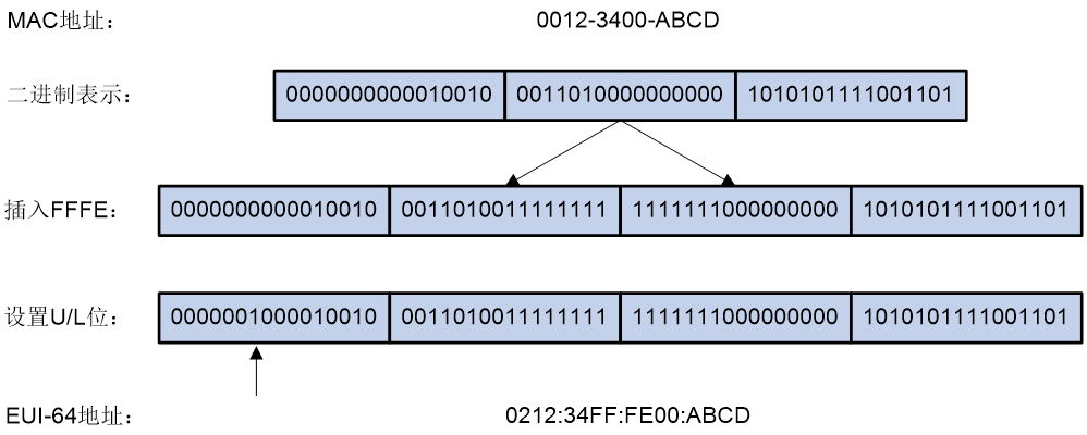
· For all IEEE 802 interface types (for example, Ethernet interfaces and VLAN interfaces): The IEEE EUI-64 format interface ID is derived from the interface's link-layer address (MAC address). The interface ID in an IPv6 address is 64-bit long, while the MAC address is 48-bit long. To create the interface ID, the hexadecimal value FFFE (1111111111111110) is inserted in the middle of the MAC address, starting from the 24th bit (counting from the highest bit). For the interface ID to have the same scope as the original MAC address, the Universal/Local (U/L) bit, which is the 7th bit counting from the highest bit, is inverted. The resulting value is then used as the EUI-64 format interface ID.
Figure 4 Process of converting a MAC address to a EUI-64 format interface ID
· Tunnel interfaces: The low 32 bits of the IEEE EUI-64 format interface ID are the source IPv4 address of the tunnel interface. For ISATAP tunnels, the high 32 bits of the interface ID are set to 0000:5EFE. For other tunnel interfaces, the high 32 bits of the interface ID are set to all zeros.
· Other interface types (such as serial interfaces): The IEEE EUI-64 format interface ID for these interfaces is randomly generated by the device.
Auto generation of IPv6 addresses with constantly changing interface IDs
When an interface of an IEEE 802 type (Ethernet or VLAN) generates an IPv6 global unicast address based on stateless address autoconfiguration, the interface ID is generated from the interface MAC address following certain rules. This interface ID is globally unique. However, the interface ID portion remains unchanged for different prefixes. Attackers can easily identify the device responsible for generating the communication traffic by analyzing the interface ID and its patterns. This can potentially create security vulnerabilities.
In stateless address autoconfiguration, to enhance the difficulty of attacks and protect the network, devices offer a temporary address feature. With this feature, devices can generate IPv6 addresses with constantly changing interface IDs. For IEEE 802 type interfaces, the following types of addresses can be simultaneously generated:
· Public address: The address prefix is obtained from the prefix carried in RA messages, and the interface ID is derived from the MAC address. The interface ID remains unchanged.
· Temporary address: The address prefix is obtained from the prefix carried in RA messages, and the interface ID is calculated by the system using the MD5 algorithm. The interface ID changes constantly.
After you specify the preference for temporary addresses, the system prioritizes selecting a temporary address as the source address for packets. When the valid lifetime of a temporary address expires, that temporary address is removed, and the system generates a new temporary address with a different interface ID using the MD5 algorithm. As a result, the interface ID of the source address for packets sent from that interface consistently changes. If a generated temporary address is unavailable due to a DAD conflict, the public address is used as the source address for the packets.
Prefix readdressing
Stateless address autoconfiguration allows users to easily and transparently switch to a new network prefix to achieve prefix readdressing. The steps for prefix readdressing are:
1. The router publishes the old IPv6 prefix on the local link through RA messages and sets the valid lifetime and preferred lifetime of the old prefix to near-zero values.
2. The router publishes the new IPv6 prefix on the local link through RA messages.
3. The node generates two IPv6 addresses based on both the old and new prefixes, and both the old and new IPv6 addresses exist simultaneously. Connections using the old IPv6 address can still be processed, while new connections use the new IPv6 address. After the valid lifetime of the old IPv6 address ends, the address is no longer used, and the node only uses the new IPv6 address to communicate.
Stateful address autoconfiguration (DHCPv6)
Dynamic Host Configuration Protocol for IPv6 (DHCPv6) is a protocol designed for IPv6 addressing scheme. It is used to allocate IPv6 prefixes, IPv6 addresses, and other network configuration parameters to hosts.
DHCPv6 advantages
Compared to other IPv6 address allocation methods such as manual configuration and stateless address autoconfiguration, DHCPv6 offers the following advantages:
· Better control over address allocation: DHCPv6 allows for recording and management of assigned addresses, including the ability to assign specific addresses to specific hosts, enhancing network management capabilities.
· Prefix delegation to DHCPv6 clients: DHCPv6 clients can be assigned a prefix, which they can then advertise to hosts, enabling stateless autoconfiguration of IPv6 addresses. This approach reduces the number of IPv6 addresses managed by the DHCPv6 server and enables automatic configuration and management across the entire network.
· In addition to IPv6 prefixes and addresses, DHCPv6 can also allocate network configuration parameters such as DNS servers and domain suffixes to hosts.
DHCPv6 address/prefix allocation process
The process of DHCPv6 server allocating addresses/prefixes to clients can be divided into the following categories:
· Rapid allocation process: This process involves the exchange of two messages to quickly allocate addresses/prefixes to clients.
Figure 5 Rapid allocation of addresses/prefixes

As shown in Figure 5, the rapid allocation process for addresses/prefixes is as follows:
a. The DHCPv6 client includes the Rapid Commit option in the Solicit message sent to the DHCPv6 server, indicating that the client wants the server to quickly allocate addresses/prefixes and other network configuration parameters.
b. If the DHCPv6 server supports the rapid allocation process, it directly responds with a Reply message, allocating IPv6 addresses/prefixes and other network configuration parameters to the client. If the DHCPv6 server does not support the rapid allocation process, it uses the normal allocation process involving four message exchanges to allocate IPv6 addresses/prefixes and other network configuration parameters to the client.
· Normal allocation process: This process involves the exchange of four messages to allocate addresses/prefixes to clients.
Figure 6 Normal allocation of addresses/prefixes

The four-message exchange process is described in Table 3.
Table 3 Normal allocation of addresses/prefixes
|
Step |
Sent message |
Description |
|
1 |
Solicit |
The DHCPv6 client sends this message to request the DHCPv6 server to assign an IPv6 address/prefix and network configuration parameters to it. |
|
2 |
Advertise |
If the Solicit message does not include the Rapid Commit option, or if the server does not support rapid allocation, the DHCPv6 server responds to notify the client of the allocable addresses/prefixes and network configuration parameters. |
|
3 |
Request |
If the DHCPv6 client receives multiple Advertise messages from servers, it selects one server based on factors such as the order of message reception and server priority. The client then sends a Request message to that server, requesting confirmation for the allocation of addresses/prefixes and network configuration parameters. |
|
4 |
Reply |
The DHCPv6 server responds to the message by confirming that it will allocate the addresses/prefixes and network configuration parameters to the client for use. |
Address/prefix lease renewal process
The IPv6 address/prefix assigned to the client by the DHCPv6 server has a lease, which is a specific time period for usage. The lease term is determined by the effective service life. After the lease time of the address/prefix reaches its valid lifetime, the DHCPv6 client can no longer use that address/prefix. Before the valid lifetime expires, if the DHCPv6 client intends to continue using the address/prefix, you must request an extension of the address/prefix lease.
Figure 7 Updating the address/prefix lease through Renew

As shown in Figure 7, when the address/prefix lease time reaches time T1 (recommended value is half of the preferred lifetime), the DHCPv6 client sends a Renew message to the DHCPv6 server that assigned the address/prefix for lease renewal. If the client can continue to use the address/prefix, the DHCPv6 server responds with a Renewal Reply message to notify the client that the address/prefix lease has been successfully updated. If the address/prefix cannot be reassigned to the client, the DHCPv6 server responds with a Renewal Failure Reply message to inform the client that it cannot obtain a new lease.
Figure 8 Updating the address/prefix lease through Rebind

As shown in Figure 8, if a Renew request to update the lease is sent at T1, but no response message is received from the DHCPv6 server, the DHCPv6 client sends a Rebind message to all DHCPv6 servers via multicast at T2 (recommended value is 0.8 times the preferred lifetime) to request updating the lease. If the client can continue to use the address/prefix, the DHCPv6 server responds with a Renew Success Reply message, notifying the DHCPv6 client that the address/prefix lease has been successfully updated. If the address/prefix cannot be reassigned to the client, the DHCPv6 server responds with a Renew Failure Reply message, notifying the client that it cannot obtain a new lease. If the DHCPv6 client does not receive a response from the server, it stops using the address/prefix after the valid lifetime expires.
DHCPv6 option introduction
Option 17 is called Vendor-specific Information, a reserved option specified in RFC.
When the device acts as a DHCPv6 server, it can use this option to carry additional network parameters (such as TFTP server name, address, or device configuration file name) and send them to DHCPv6 clients in order to provide corresponding services to the clients.
To provide scalability and allocate more information to clients through Option 17, Option 17 uses sub-options to assign different network configuration parameters to users. Currently, users can configure up to 16 sub-options under each vendor custom option.
· Option 18
Option 18 is called Interface ID option. After receiving a DHCPv6 request message from a DHCPv6 client, the device adds Option 18 (DHCPv6 relay will add Option 18 in the Relay-forward message) in the message and forwards it to the DHCPv6 server. The server can assign IPv6 addresses to DHCPv6 clients from the appropriate address pool based on client information in Option 18. Figure 9 shows the Option 18 format.
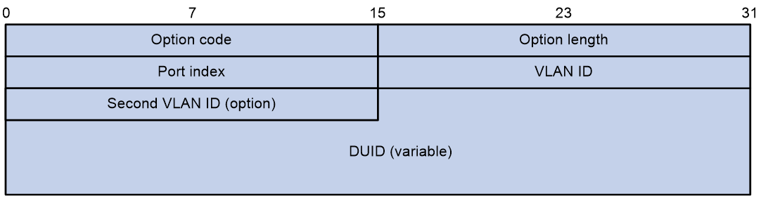
The fields are described as follows:
¡ Option code: Option number, with a value of 18.
¡ Option length: Length of the Option field.
¡ Port index: Port index where the DHCPv6 device receives the client request message.
¡ VLAN ID: First layer VLAN information.
¡ Second VLAN ID: Layer 2 VLAN information. The Second VLAN ID field in the option format is optional. If the DHCPv6 message does not contain a Second VLAN, the Option 18 also does not include the Second VLAN ID content.
¡ DUID: By default, it is the DUID information of the device itself. It can be configured as other DUID information through the CLI.
Option 37 is known as the Remote ID option. After receiving a DHCPv6 request message from a DHCPv6 client, the device adds the Option 37 option to the message (the DHCPv6 relay will add the Option 37 option to the Relay-forward message) and forwards it to the DHCPv6 server. The server can locate DHCPv6 clients and assist in assigning IPv6 addresses based on the information in Option 37. Figure 10 shows the Option 37 format.
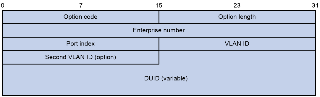
The fields are described as follows:
¡ Option code: Option number, with a value of 37.
¡ Option length: Length of the Option field.
¡ Enterprise number: Enterprise identifier.
¡ Port index: Port index where the DHCPv6 device receives the client request message.
¡ VLAN ID: First layer VLAN information.
¡ Second VLAN ID: Layer 2 VLAN information. The Second VLAN ID field in the option format is optional. If the DHCPv6 message does not contain a Second VLAN, the Option 37 also does not include the Second VLAN ID content.
¡ DUID: By default, it is the DUID information of the device itself. It can be configured as other DUID information through the CLI.
Option 79 is called the Client Link Layer Address option. When the DHCPv6 request message passes through the first DHCPv6 relay, the relay learns the source MAC address of the message, which is the MAC address of the DHCPv6 client. When the DHCPv6 relay generates a Relay-Forward message corresponding to the request, it adds the learned MAC address to Option 79 and then forwards the message to the DHCPv6 server. The DHCPv6 server can learn the MAC address of the DHCPv6 client based on the information in Option 79, which helps with IPv6 address/prefix allocation or client legitimacy authentication. Figure 11 shows the Option 79 format.
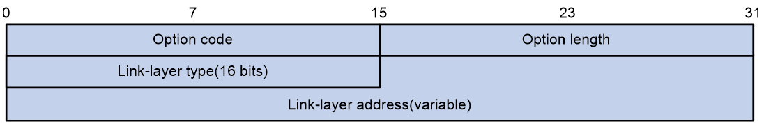
The fields are described as follows:
¡ Option code: Option number, with a value of 79.
¡ Option length: Length of the Option field.
¡ Link-layer type: Client link layer address type.
¡ Link-layer address: Client Link-layer address.
IPv6 deployment plan
IPv6 upgrade and transformation plan
IPv6 upgrade and transformation plan includes the following options:
· Create an IPv6 network.
· Deploy dual-stack for specific devices
· Perform address translation at network boundaries.
Creating an IPv6 network
IPv6 network creation refers to the formation of a completely new IPv6 network according to the existing network construction model. All devices in the network support IPv4 and IPv6 dual-stack, and this network is only used to handle IPv6 traffic. In a brand new IPv6 network, new services can be deployed to achieve service innovation.
Figure 12 IPv6 network creation
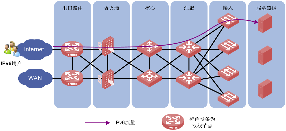
Deploying dual-stack on specific devices
Deploying dual-stack on specific devices refers to the support of dual stack in only the network egress, firewall, core devices, and some aggregation/access devices. IPv6 users communicate through these dual stack nodes.
Figure 13 Deploying dual-stack on specific devices
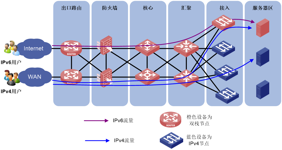
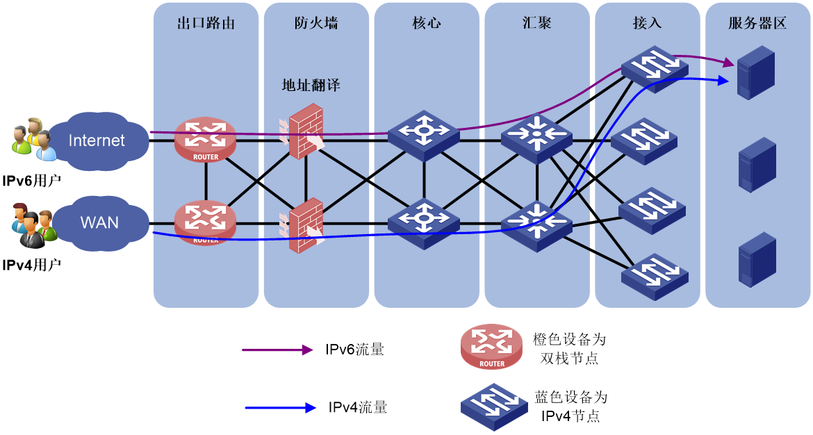
Performing address translation at network boundaries
Address translation for network boundaries refers to enabling address translation protocols such as AFT on firewalls located at the boundary between IPv4 and IPv6 networks to convert IPv4 and IPv6 addresses to each other. This enables IPv6 users to access IPv4 networks.
Figure 14 Performing address translation at network boundaries
Comparison of upgrade and transformation plans
The comparison of the three plans for upgrading and transforming IPv6 networks are as shown in the following table.
Table 4 Comparison of upgrade and transformation plans
|
Upgrade and transformation plan |
Create an IPv6 network |
Deploy dual-stack on specific devices |
Perform address translation at network boundaries |
|
Transformation cost |
High |
Medium |
Low |
|
Difficulty of transformation |
Low |
High |
Low |
|
Transformation workload |
Medium |
Medium |
Low |
|
Transformation risks |
Low |
High |
Medium |
|
Impact on existing services |
No impact. This plan redeploys IPv6 services completely. |
IPv4 and IPv6 applications reuse dual-stack networks. |
No impact. The original IPv4 services do not require address translation. |
|
Single device pressure |
Low IPv4 and IPv6 networks are handled by different devices for IPv4 and IPv6 traffic. |
Medium Network, firewall, and other nodes must be deployed with dual-stack protocols and share device resource table entries. |
High The node of address translation becomes a network bottleneck. |
|
Operation complexity |
Separated operation and maintenance interfaces for IPv4 and IPv6 to provide simplified operation and maintenance. |
Mixed operation and maintenance interface for IPv4 and Ipv6 with complex operation and maintenance. |
Continue with IPv4 operation and maintenance, which is simple to operate. |
|
Application scenarios |
Important service systems with complex architectures and high remodeling difficulties, such as financial online banking services Networks with service innovation requirements. |
Clear and simple network structure. |
Tight budget or desire to minimize the impact of IPv6 on the existing network. |
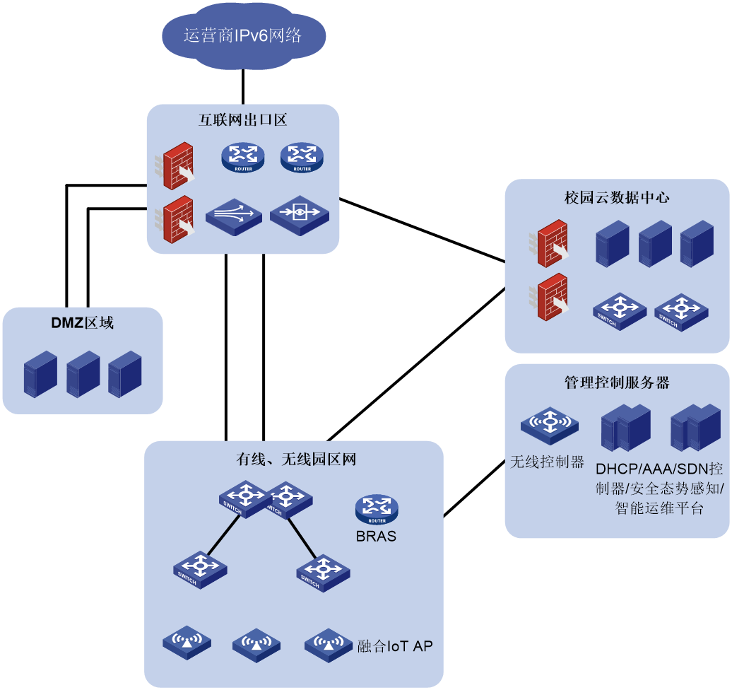
Comprehensive IPv6 deployment plan for campus networks
The typical deployment scheme for the full IPv6 transformation of the campus network is shown in Figure 15. The specific deployment method is:
· Internet egress zone:
¡ Firewalls, IPS, LB, application control, and traffic analysis devices fully support IPv6.
¡ Fully support address translation protocols such as AFT.
· Campus cloud data center:
¡ Underlay and Overlay networks support IPv6.
¡ Virtualization and cloud platform fully support IPv6.
¡ Deploy AFT and other address translation protocols.
· Management control server zone:
¡ Security situation awareness supports IPv6.
¡ Authentication, authorization, and network management servers support IPv6.
· Wired and wireless campus networks:
¡ Support IPv6 address allocation and IPv6 routing protocols.
¡ Support IPv6 access (BRAS or ADCampus).
¡ Support wired and wireless access for SAVA and intra-domain SAVA to prevent source address spoofing attacks.
· DMZ zone: Set up DNS64, and make external websites IPv6-enabled.
Figure 15 Comprehensive IPv6 deployment for campus networks
IPv6 transformation plan for financial networks
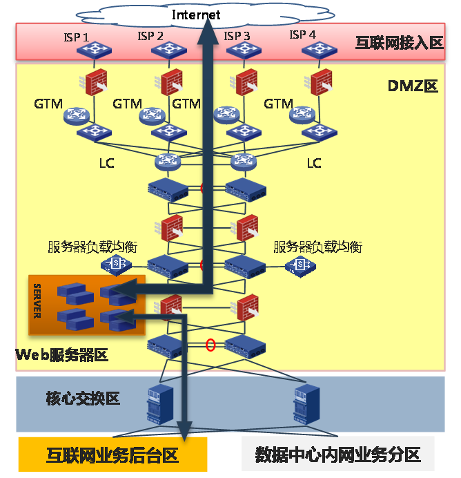
As shown in Figure 16, a financial network contains the following components:
· Internet access zone: User network access is completed through the ISP's Internet line. WAN access routers are deployed in this zone to achieve multiple ISP's access to multiple Internet lines.
· Demilitarized Zone (DMZ): The server that provides web services for users is located in the DMZ zone. Use firewalls and IPS to achieve Internet and DMZ isolation, deploy routers and switches within the DMZ to achieve interconnectivity of all devices in this zone, and use load balancing devices to optimize the service response speed and ensure high availability of web services.
· Core switch zone: Connect DMZ zone and Internet service backend zone, as well as the data center intranet server zone.
· Internet service backend zone: Mainly provides application processing for portals, online banking, and Internet financial services.
· Data center intranet server zone: Includes multiple service zones, mainly providing data services for APP servers or DB.
Figure 16 Financial network architecture
Financial networks can be upgraded from IPv4 to IPv6 using the following solutions:
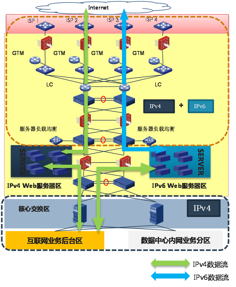
· Create a new pure IPv6 zone: Establish a pure IPv6 Internet access zone and DMZ zone. The Internet access zone and DMZ zone provide Web services externally through IPv6 and connect data via IPv4 to the backend service backend zone and internal service zone.
Figure 17 Completely newly built pure IPv6 zone
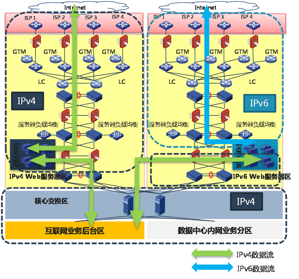
· Build an IPv6 web server cluster: Upgrade the Internet access zone and DMZ zone to support dual stack. The existing IPv4 web server cluster and the newly built IPv6 web server cluster share the dual stack network.
Figure 18 Creating an IPv6 web server cluster
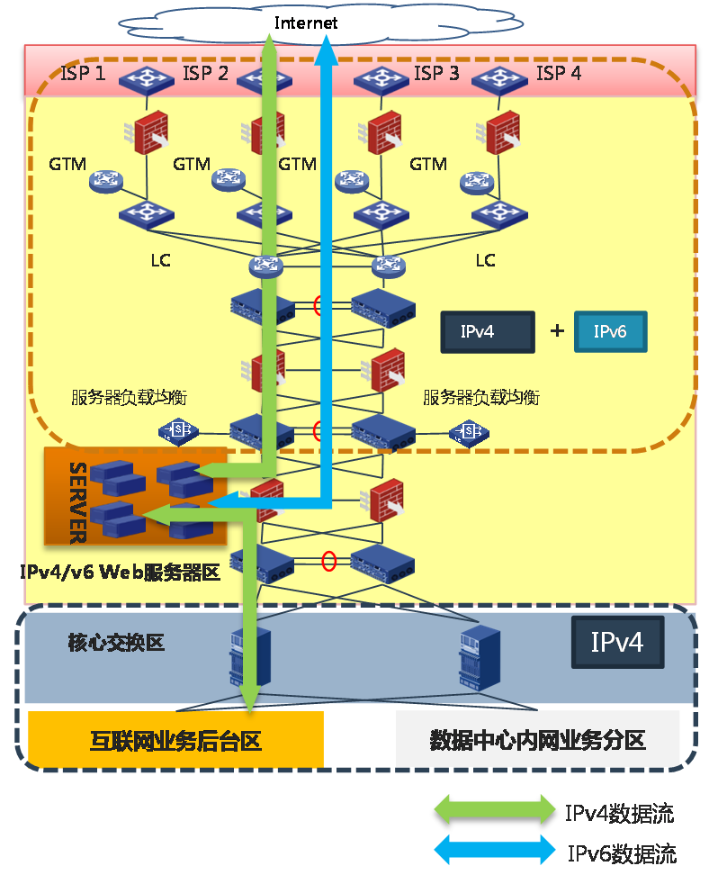
· Upgrade the original web server cluster network to a dual-stack network: Modify the Internet access zone, DMZ zone, and web server cluster network to support dual-stack.
Figure 19 Upgrading the original web server cluster network to a dual-stack network
E-government external network IPv6+ applications
SRv6 application
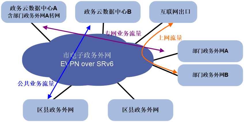
The deployment scheme for SRv6 in the external e-government network is shown as Figure 20.
· Internet access traffic is carried through EVPN over SRv6, assigning corresponding VPN permissions to Internet users, and carrying traffic through SRv6 tunnels.
· Public service traffic can use public addresses and be carried directly through SRv6.
· Special network traffic is divided into corresponding EVPN to ensure the network is dedicated and service logic is isolated.
· All paths can be dynamically adjusted by the SDN controller to ensure optimal resource usage.
Figure 20 SRv6 application in the external network of e-government
Network slicing application
The deployment scheme for network slicing in the e-government extranet is shown in Figure 21.
· By using various network slicing technologies, the backbone network bandwidth is refined to form multiple channels.
· According to different service needs (latency/jitter/packet loss), different strategies are distributed through the controller to achieve diversified utilization of channels.
· Different bandwidths can be allocated to different private networks (such as emergency command networks, video conference networks, document downloading networks) according to their requirements, ensuring that the traffic of one network will not be dropped due to congestion from another network in the same topology.
· According to customer's service requirements, the SRv6 forwarding path can be flexibly arranged to enhance network intelligence.
Figure 21 Network slicing application of the e-government external network

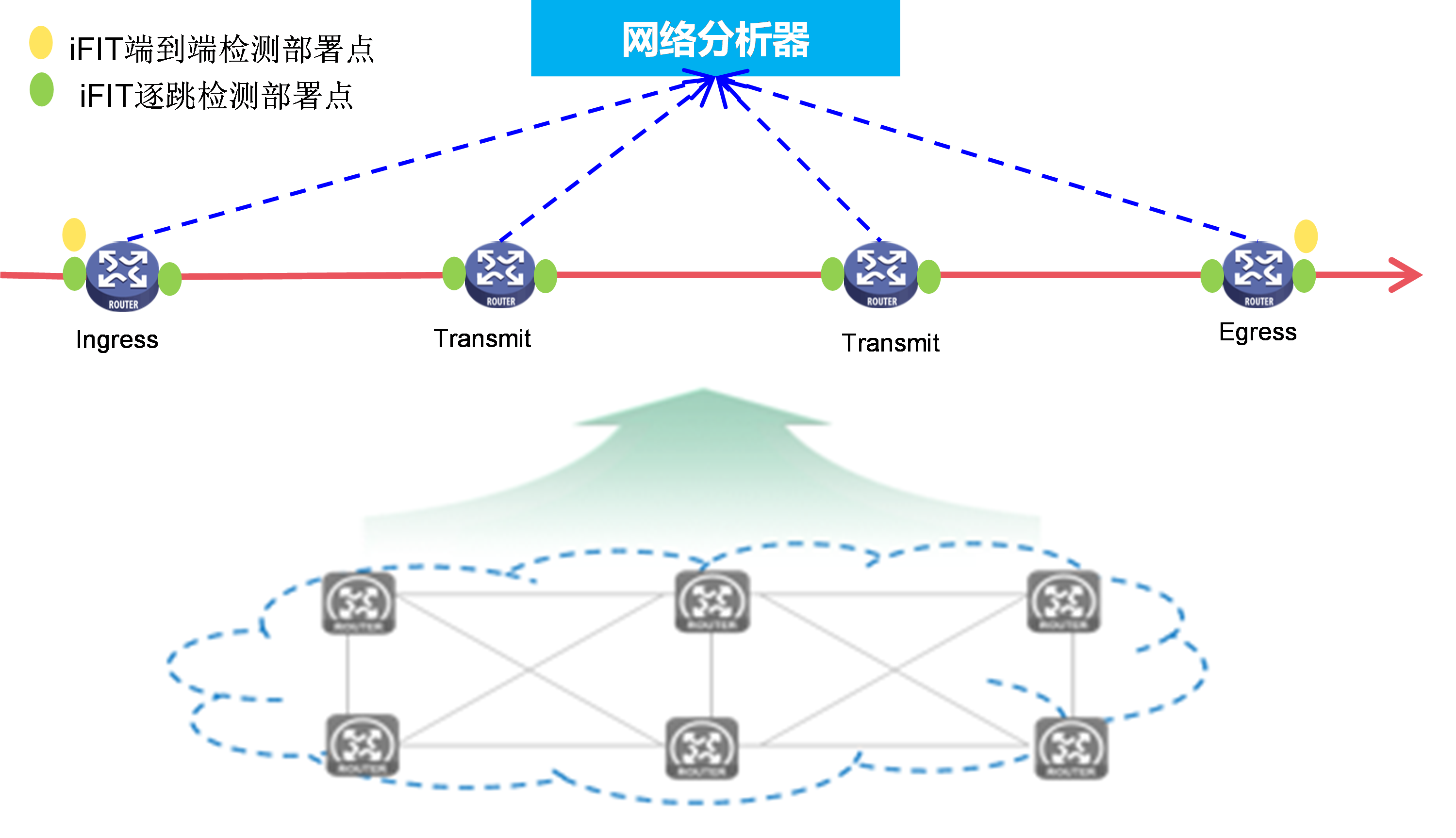
Visualization application
The deployment plan for the visualized e-government extranet is shown as follows in Figure 22. The visualization solution based on iFIT and Telemetry technology enables the following:
· Quality visibility and planning support: Periodic data collection generates real-time report data, providing data support for capacity expansion and subsequent planning.
· Move with demand and intelligent O&M: Achieve intelligent optimization of network paths based on current network service status, ensuring the quality of critical service operations.
· Accurate positioning and fast troubleshooting: When service issues occur, problems can be quickly identified and resolved through the graphical display on the network analyzer.
|
|
NOTE: For more information about Telemetry, see Telemetry Technology White Paper. |
Figure 22 Visualization application of e-government external network
IPv6 DNS
About IPv6 DNS
A domain name system (DNS) is a distributed database system that provides domain name-to-IP address mappings for TCP/IP applications. With DNS, users using IP applications can directly use meaningful easy-to-remember domain names, which will be resolved and mapped to corresponding IP addresses by DNS servers.
On an IPv6 network, DNS uses AAAA and PTR records to realize translation between domain names and IPv6 addresses.
· AAAA record—Maps a domain name to an IPv6 address, which is used for forward resolution.
· PTR record—Maps an IPv6 address to a domain name, which is used for reverse resolution.
External link access failure prevention
During IPv4-to-IPv6 network transition, both kinds of networks will coexist for a period of time. When a user accesses an IPv6 website containing links to other websites (external links) that do not support IPv6, the user might experience such issues as slow response, incomplete contents, and feature usage failure.
External link access failure prevention for a dual-stack endpoint
As shown in Figure 23, the dual-stack endpoint regards the IPv4 website link as an IPv6 website link when it accesses the IPv6 website. The endpoint requests the AAAA record from the DNS server, but the DNS server does not have a corresponding AAAA record for the IPv4 website. As a result, domain name resolution fails.
Figure 23 External link access failure
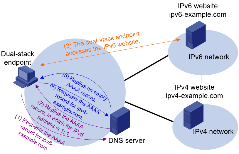
To solve such an issue:
1. The dual-stack endpoint sends an IPv6 DNS request to the DNS server for the AAAA record of the external link domain name.
2. The dual-stack endpoint sends an IPv4 DNS request to the DNS server for the A record of the external link domain name.
3. If the dual-stack endpoint receives the AAAA record, it sends a connection request to the IPv6 address in the AAAA record and establishes an IPv6 connection.
4. If the dual-stack endpoint fails to receive the AAAA record or establish an IPv6 connection, it sends a connection request to the IPv4 address in the A record and establishes an IPv4 connection.
External link access failure prevention for an IPv6-only client
To access a website containing an IPv4 external link, an IPv6-only client sends a DNS request to the local DNS server for resolving the associated domain name. Without external link proxy configured, the domain name resolution will fail, and the IPv6 client cannot access the resource associated with the external link.
With external link proxy configured, the LB device returns an external link rewrite script file when responding to the access request from the IPv6 client. The client executes the script file, modifies the external link domain name, and then sends another DNS request containing the modified domain name. The local DNS server queries the modified domain name and redirects the request to the LB device. The LB device will request the external link resource on behalf of the IPv6 client and return the resource to the client.
Figure 24 External link proxy working mechanism
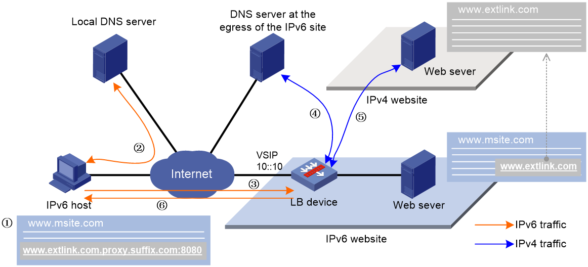
As shown in Figure 24, the working mechanism of external link proxy is as follows:
1. The IPv6 host executes the script file, and modifies the external link domain name as http://www.extlink.com.proxy.suffix.com.
2. The IPv6 host sends a DNS request to the local DNS server to query the domain name http://www.extlink.com.proxy.suffix.com. Based on the query result, the local DNS server notifies the IPv6 host of the LB device as the authoritative DNS server.
3. The IPv6 host sends a DNS request to the LB device to query domain name http://www.extlink.com.proxy.suffix.com.
4. Upon receiving the DNS request, the LB device sends a DNS request to the DNS server to query the IPv4 address associated with the original domain name http://www.extlink.com.
5. The LB device obtains the resource associated with the external link based on the IPv4 address.
6. The LB device sends the obtained resource to the IPv6 host.
7. The IPv6 host resolves the resource and displays a normal website.
IPv6 routing
RIP, OSPF, IS-IS, and BGP are important routing protocols for IPv4 networks. These routing protocols must be extended and upgraded for compatibility with IPv6 networks. Their extended versions are called RIPng, OSPFv3, IPv6 IS-IS, and IPv6 BGP, respectively. Unlike IPv4 routing protocols, IPv6 routing protocols must adjust their routing processes to accommodate to IPv6 addresses and IPv6 networks. Despite this difference, there is no essential difference between IPv4 routing protocols and IPv6 routing protocols in terms of application scenarios, routing mechanisms, pros and cons.
RIPng
RIP has two versions: RIPv1 and RIPv2.
· RIPv1 is a classful routing protocol. It advertises messages only through broadcast. Because RIPv1 messages do not carry mask information, RIPv1 can only recognize natural networks such as Classes A, B, and C, and it does not support non-contiguous subnets.
· RIPv2 is a classless routing protocol. It has the following advantages over RIPv1:
¡ Supports route tags for flexible route control through routing policies.
¡ Supports masks, route summarization, and Classless Inter-Domain Routing (CIDR).
¡ Supports designated next hops on broadcast networks.
¡ Supports multicasting route updates to reduce resource consumption.
¡ Supports plaintext authentication and MD5 authentication by adding an authentication route entry (RTE) into updates to enhance data security.
RIPng operates in the same way as RIPv2 except that RIPng contains some modifications to support IPv6. RIPng is different from RIPv2 in terms of the following aspects:
IP address length
RIPng routes use 128-bit IPv6 addresses. RIPv2 routes use 32-bit IPv4 addresses.
Packet length
A RIPv2 packet can carry a maximum of 25 RTEs. The maximum number of RTEs in a RIPng packet depends on the IPv6 MTU of the sending interface.
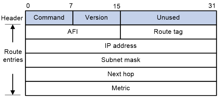
Packet format
As shown in 0, a RIPv2 packet contains a header and multiple RTEs.
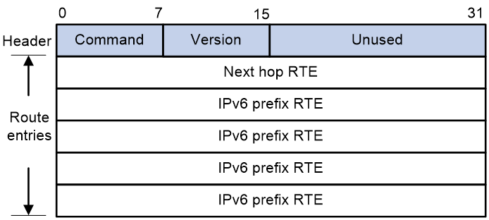
As shown in 0, a RIPng packet contains a header and the following types of RTEs:
· Next hop RTE—Defines the IPv6 address of a next hop.
· IPv6 prefix RTE—A next hop RTE can be followed by multiple IPv6 prefix RTEs. An IPv6 prefix RTE describes the destination IPv6 address, route tag, prefix length, and metric in a RIPng route entry.
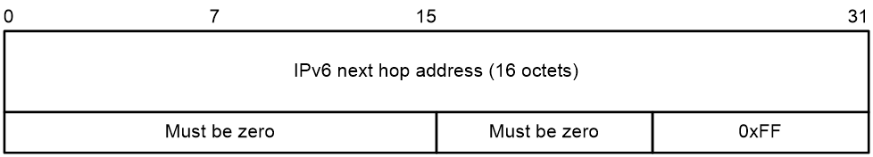
0 shows the format of a next hop RTE.
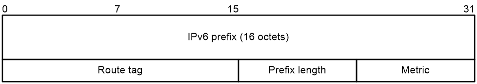
0 shows the format of an IPv6 prefix RTE:
· IPv6 prefix—Destination IPv6 address prefix.
· Route tag—Route tag.
· Prefix length—Length of the IPv6 address prefix.
· Metric—Cost of the route.
Packet sending mode
RIPv2 can periodically send routing information through broadcast or multicast as configured. RIPng periodically sends routing information only through multicast.
Packet authentication
RIPv2 uses authentication RTEs for packet authentication. RIPng uses the authentication mechanism of IPv6 for packet authentication.
Compatibility with network layer protocols
RIP can run in IP networks and IPX networks. RIPng can run in IPv6 networks only.
OSPFv3
OSPFv3 works basically in the same way as OSPFv2 but has some differences from OSPFv2 to support IPv6 address format.
Similarities between OSPFv3 and OSPFv2
OSPFv3 and OSPFv2 are similar in terms of the following aspects:
· Packet types: hello, DD, LSR, LSU, and LSAck.
· Area partition.
· LSA flooding and synchronization mechanisms: Both OSPFv3 and OSPFv2 use reliable flooding and synchronization to ensure correct LSDB contents.
· Routing calculation method: SPF algorithm
· Network types: broadcast, NBMA, P2MP, and P2P.
· Neighbor discovery and adjacency establishment mechanisms: When a router starts, it sends a hello packet via an OSPF interface, and the peer that receives the hello packet checks parameters carried in the packet. If parameters of the two routers match, they become neighbors. Not every pair of neighboring routers become adjacent, which depends on network types. Two OSPF neighbors can form an adjacency only after they successfully exchange DD packets and LSAs and complete LSDB synchronization.
· DR election: It is required to elect the DR and BDR on NBMA and broadcast networks.
Differences between OSPFv3 and OSPFv2
Some necessary modifications are made to OSPFv2 so that OSPFv3 can support IPv6. This makes OSPFv3 independent of network layer protocols and compatible with different protocols.
OSPFv3 is different from OSPFv2 as follows:
· Protocol running per-link, not per-subnet
OSPFv2 runs on a per-IP subnet basis. With OSPFv2 enabled, two routers can establish a neighbor relationship only when they run on the same subnet.
OSPFv3 runs on a per-link basis. A single link can have multiple IPv6 subnets (IPv6 prefixes). Two nodes can directly communicate with each other over a single link, even if their IPv6 prefixes are different.
· Use of link-local addresses
When an OSPFv3 router sends packets on an interface, the source address of these packets is the link-local address of that interface. The router learns the link-local addresses of other routers that are attached to the same link as the router, and uses these addresses as next hops for packet forwarding. For virtual links, the source IP addresses of OSPFv3 packets must be IPv6 global unicast addresses.
Link-local addresses are meaningful only for local links and can be flooded on the local links only. Therefore, Link-LSAs can carry link-local addresses.
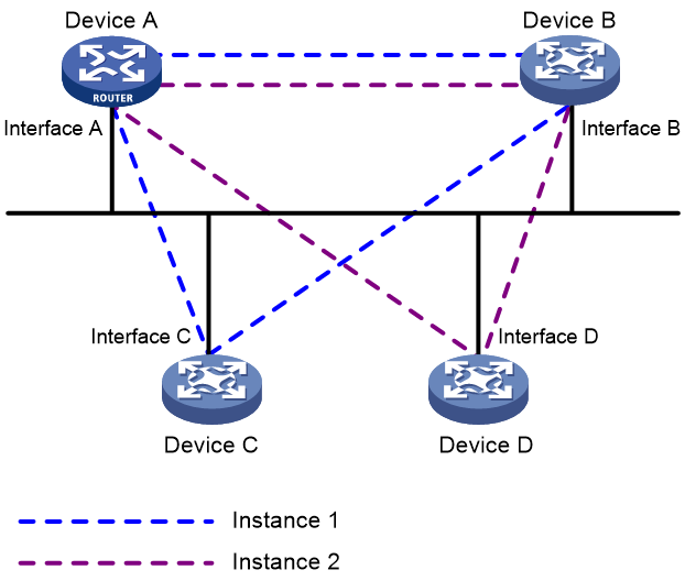
· Support for multiple instances per link
As shown in Figure 25, multiple OSPFv3 instances can run on a single link, which reduces network deployment costs.
Device A, Device B, Device C, and Device D are attached to the same broadcast network and share the same link. OSPFv3 instance 1 is enabled on Interface A, Interface B, and Interface C, so that Device A, Device B, and Device C can establish neighbor relationships with each other. OSPFv3 instance 2 is enabled on Interface A, Interface B, and Interface D, so that Device A, Device B, and Device D can establish neighbor relationships with each other.
For a link to support multiple OSPFv3 instances, OSPFv3 adds the Instance ID field into packets headers. On receipt of an OSPFv3 packet, an interface must match the instance ID carried by the packet against its own instance ID. If the two instance IDs are different, the interface discards the packet and does not establish a neighbor relationship with the source address of the packet.
Figure 25 Running of multiple instances on a link
· Identifying neighbors by router ID
Unlike OSPFv2, OSPFv3 identifies neighbors only by router ID.
· Authentication changes
OSPFv3 supports packet authentication and can use the security mechanism of IPv6 to ensure packet validity.
· Stub area support for unknown LSAs
OSPFv3 supports flooding unknown LSAs. To control the number of unknown LSAs in the stub area, OSPFv3 floods an unknown LSA to the stub area only when the LSA meets the following requirements:
¡ The LSA is flooded within a link or area.
¡ The U bit of the LSA is not set.
· Packet formats
OSPFv3 packets are encapsulated into IPv6 packets. Each OSPFv3 packet begins with a 16-byte header. The header format varies by OSPFv3 packet type.
OSPFv3 and OSPFv2 use the same LSU and LSAck packet formats, but their packet header formats and hello packet formats are different:
¡ The version number is 2 for OSPFv2 and is 3 for OSPFv3.
¡ Compared with OSPFv2 packet headers, the length of OSPFv3 packet headers is 16 bytes with the Authentication field eliminated and the Instance ID field added. The Instance ID field enables a link to support multiple OSPFv3 instances and takes effect on only local links.
¡ Compared with OSPFv2 hello packets, OSPFv3 hello packets do not carry the Network Mask field. The Interface ID field is added to OSPFv3 hello packets to identify source interfaces.
· Options field
The Options field is supported only by OSPFv2 hello packets, DD packets, and LSAs.
The Options field is supported only by OSPFv3 hello packets, DD packets, Router LSAs, Network LSAs, Inter-Area-Router LSAs, and Link LSAs.
Figure 26 shows the Options field format of OSPFv2 and Figure 27 shows the Options field format of OSPFv3.
Figure 26 OSPFv2 Options field format
![]()
Figure 27 OSPFv3 Options field format
![]()
OSPFv3 adds the R and V bits into the Options field:
¡ R bit—This bit indicates whether the originator is an active router. If the R bit is clear, the originator's routes do not participate in route calculation. Clearing the R bit would be appropriate for a device that wants to participate in routing, but does not want to forward non-locally addressed packets.
¡ V bit—If this bit is clear, the router/link should be excluded from IPv6 routing calculation.
OSPFv3 uses seven types of LSAs. The following table compares OSPFv3 LSAs and OSPFv2 LSAs.
Table 5 Comparisons between OSPFv3 and OSPFv2 LSAs
|
OSPFv2 LSA |
OSPFv3 LSA |
Comparison |
|
Router LSA |
Router LSA |
OSPFv3 Router LSAs and Network LSAs describe routing domain topology information only. |
|
Network LSA |
Network LSA |
|
|
Network Summary LSA |
Inter Area Prefix LSA |
They function similarly. |
|
ASBR Summary LSA |
Inter Area Router LSA |
|
|
AS External LSA |
AS External LSA |
Exactly the same. |
|
N/A |
Link LSA |
Available in OSPFv3 only |
|
Intra Area Prefix LSA |
Available in OSPFv3 only |
OSPFv3 has two new LSA types: Link LSA and Intra Area Prefix LSA.
¡ OSPFv3 Router LSAs does not contain address information. An OSPFv3 router originates a separate Link LSA for each attached link. A Link LSA advertises the router's link-local address and a list of IPv6 prefixes to all other routers attached to the link.
¡ Router LSAs and Network LSAs do not carry route information, which is carried by Intra-Area-Prefix LSAs. An Intra-Area-Prefix LSA can advertise one or more IPv6 address prefixes.
· Expansion of LSA flooding scopes
OSPFv3 has expanded LSA flooding scopes. The flooding scope of an LSA is defined in its LS Type field. OSPFv3 LSAs support the following flooding scopes:
¡ Link-local scope—The LSA is flooded only on the local link. It is used for new Link LSAs.
¡ Area scope—The LSA is flooded throughout the single OSPF area only. It is used for Router LSAs, Network LSAs, Inter-Area-Prefix LSAs, Inter-Area-Router LSAs, and Intra-Area-Prefix LSAs.
¡ AS scope—The LSA is flooded throughout the routing domain. It is used for AS-external LSAs.
When an OSPFv2 interface receives an unknown LSA, it directly discards the LSA.
OSPFv3 uses the U bit in the LS Type field of LSAs to indicate the mode of processing an unknown LSA:
¡ If the U bit is set to 1, OSPFv3 will flood the unknown LSA within the flooding scope defined in the LS Type field.
¡ If the U bit is set to 0, OSPFv3 will flood the unknown LSA on the link.
To accommodate to IPv6 addresses, OSPFv3 has adjusted the LSA header format and LSA formats. For more information, see OSPFv3 Technology White Paper.
IPv6 IS-IS
To route packets in IPv6 networks, IS-IS was extended to IPv6 IS-IS.
New TLVs for IPv6 IS-IS
Type-Length-Value (TLV) is a variable part of LSPs and allows LSPs to carry different information.
IPv6 IS-IS uses two new TLVs and a Network Layer Protocol Identifier (NLPID) field with a value of 0x8E for IPv6 packet forwarding.
The type value for IPv6 Reachability TLV is 236 (0xEC). This TLV corresponds directly to Common Reachability TLV and Extended Reachability TLV in IPv4 IS-IS. Figure 28 shows the format of IPv6 Reachability TLV.
Figure 28 IPv6 Reachability TLV format
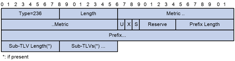
IPv6 Reachability TLV contains the following fields:
¡ Type—A value of 236 indicates that this TLV is an IPv6 reachability TLV.
¡ Length—TLV length.
¡ Metric—Extended metric, in the range 0 to 4261412864. If the metric value is greater than 4261412864, the IPv6 reachability information will be ignored.
¡ U—Up/Down bit. This bit prevents routing loops. When a route is advertised from a Level-2 router to a Level-1 router, this field is set to 1 to prevent the route from being looped back.
¡ X—Route redistribution bit. A value of 1 means the route is redistributed from another protocol.
¡ S—If a TLV does not carry any sub-TLVs, this field is set to 0. When the TLV carries sub-TLV information, this field is set to 1.
¡ Reserve—This field is reserved.
¡ Prefix Length—IPv6 route prefix length.
¡ Prefix—IPv6 prefix that the originator can reach.
¡ Sub-TLV/Sub-TLV Length—Sub-TLV and its length. These fields are optional.
The type value for IPv6 Interface Address TLV is 232 (0xE8). This TLV is similar to IPv4 Interface Address TLV except that the IPv6 TLV uses 128-bit IPv6 addresses. Figure 29 shows the format of IPv6 Interface Address TLV:
Figure 29 Format of IPv6 Interface Address TLV
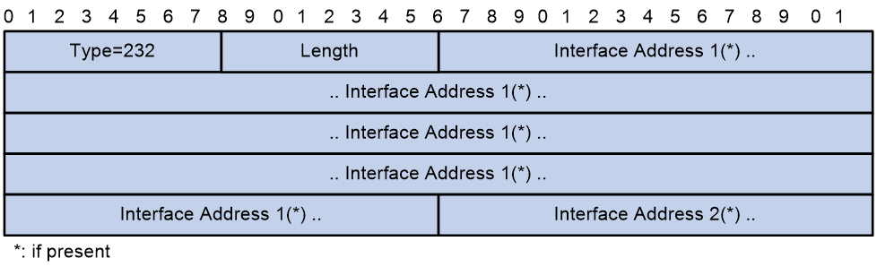
IPv6 Interface Address TLV contains the following fields:
¡ Type—A value of 236 indicates that this TLV is an IPv6 interface address TLV.
¡ Length—TLV length.
¡ Interface Address: IPv6 address of the interface enabled with IPv6 IS-IS. The interface address TLV of a hello packet carries the IPv6 link-local addresses of the interface that sent the packet. The interface address TLV of an LSP carries the IPv6 global unicast addresses assigned to the interface that sent the LSP.
If a field is asterisked, it is optional.
IS-ISv6 Adjacency
IS-IS uses hello packets to discover neighbor routers on the same link and establish adjacencies with them. After two routers become adjacent, they periodically send hello packets to each other to maintain the adjacency. To support IPv6, IPv6 IS-IS added the NLPID field and IPv6 Interface Address TLV to hello packets:
· NLPID is an 8-bit field that identifies the network protocol supported by IS-IS. For IPv6 IS-IS, the value for this field is 142 (0x8E). If a device supports IPv6 IS-IS, its neighbors can obtain this support information by reading the NLPID field in the hello packets received from the device.
· When a device receives a hello packet from a neighbor, it can obtain the IPv6 link-local addresses of the interface that sent the hello packet by reading the Interface Address field of IPv6 Interface Address TLV.
IPv6 BGP (also called BGP4+)
To support multiple network layer protocols, IETF upgraded BGP-4 to Multiprotocol BGP (MP-BGP). IPv6 BGP implements inter-AS IPv6 route transmission based on MP-BGP.
BGP-4 carries IPv4 route information in UPDATE messages, including the NLRI attribute and the NEXT_HOP attribute. To support IPv6, MP-BGP extended the NLRI and NEXT_HOP attributes:
· Two new route attributes, MP_REACH_NLRI and MP_UNREACH_NLRI, are introduced to replace the NLRI field of BGP-4 and provide IPv6 support.
¡ MP_REACH_NLRI—Carries feasible route prefixes and next hops for multiple network layer protocols.
¡ MP_UNREACH_NLRI—Carries unfeasible route prefixes for multiple network layer protocols.
· BGP next hop information supports IPv6 addresses. It can be IPv6 unicast addresses or IPv6 local link addresses. This information is carried by the MP_REACH_NLRI attribute instead of the NEXT_HOP attribute.
On a developing IPv4/IPv6 hybrid network, IPv4 peers can exchange IPv6 BGP routes over IPv4 BGP sessions to support IPv6 traffic forwarding. Likewise, IPv6 peers can exchange IPv4 BGP routes over IPv6 BGP sessions to support IPv4 traffic forwarding.
Similarities and differences between IPv4 and IPv6 routing protocols
Table 6 Comparisons between IPv4 and IPv6 routing protocols
|
Routing protocols |
Similarities |
Differences |
|
Route calculation and basic operation mechanism |
· RIP and RIPng use different packet formats in terms of multicast address, UDP port, and packet content. · RIP and RIPng process next hop information differently. · RIPng ensures data security by using IPv6 headers. |
|
|
OSPFv2/OSPFv3 |
Route calculation and basic operation mechanism |
· OSPFv3 added new LSA types and adjusted LSA formats to support IPv6 route advertisement. · OSPFv3 has greater extensibility than OSPF because it is independent of network protocols. · OSPFv3 supports processing unknown LSAs. |
|
IS-IS/IPv6 IS-IS |
· IPv6 IS-IS added the NLPID field to hello packets for IPv6 support. · IPv6 IS-IS introduced IPv6 Reachability TLV and IPv6 Interface Address TLV. |
|
|
BGP-4/IPv6 BGP |
Protocol architecture |
· IPv6 BGP upgraded the format of OPEN messages for IPv6 support. · IPv6 BGP introduced the MP_REACH_NLRI and MP_UNREACH_NLRI attributes and extended the NEXT_HOP attribute. |
Dual-stack PBR
Dual-stack policy-based routing (dual-stack PBR) uses user-defined policies to route packets. A policy can specify parameters for IPv4 or IPv6 packets that match specific criteria such as ACLs. The parameters include the next hop, output interface, default next hop, and default output interface.
Dual-stack PBR routes packets in the same way as IPv4 PBR and IPv6 PBR. However, dual-stack PBR can process both IPv4 packets and IPv6 packets.
To simplify routing configuration and save drive resources, configure dual-stack PBR on IPv4/IPv6 dual-stack nodes.
IPv6 multicast
About IPv6 multicast
Multicast enables a host to send packets to a group of hosts (a multicast group) in an IP network. The destination address in the packet is a multicast group address, and all the hosts in the multicast group can receive the packet.
As a technique that coexists with unicast and broadcast, the multicast technique effectively addresses the issue of point-to-multipoint data transmission. By enabling high-efficiency point-to-multipoint data transmission over a network, multicast greatly saves network bandwidth and reduces network load.
By using multicast technology, a network operator can easily provide bandwidth-critical and time-critical information services. These services include live webcasting, Web TV, distance learning, telemedicine, Web radio, and real-time video conferencing.
The most significant advantage of IPv6 multicast over IPv4 multicast is the greatly expanded addressing capability. Other techniques in IPv6 multicast, such as the group membership management, multicast packet forwarding, and multicast route establishment, are more or less that same as in IPv4 multicast. This document mainly describes IPv6 multicast addresses, and gives a general introduction to the differences between IPv4 multicast protocols and IPv6 multicast protocols.
IPv6 multicast address
IPv6 addresses are 128 bits long. An IPv6 address is divided into eight groups, and each 16-bit group is represented by four hexadecimal numbers, for example, FEDC:BA98:7654:3210:FEDC:BA98:7654:3210.
IPv6 multicast address format
An IPv6 multicast address identifies a group of interfaces that typically belong to different nodes. A packet sent to a multicast address will be received by all interfaces identified by the multicast address. A node can belong to one or more multicast groups.
Figure 30 shows the format of an IPv6 multicast address.
Figure 30 IPv6 multicast address format
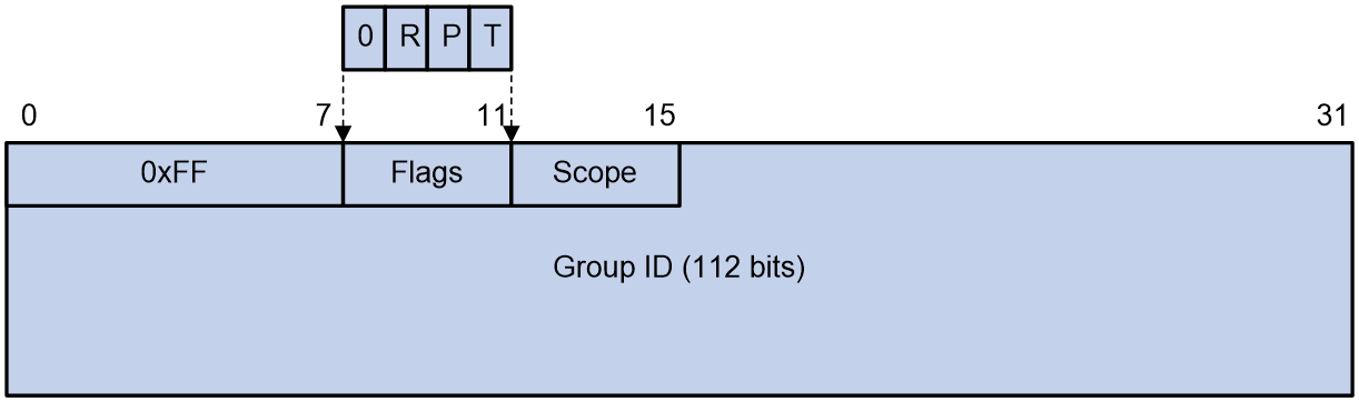
The following describes the fields of an IPv6 multicast address:
· 0xFF—Identifies an IPv6 multicast address. The most significant eight bits are 11111111.
· Flags—The Flags field contains four bits.
Table 7 Flags field description
|
Bit |
Value and meaning |
|
0 |
Reserved, must be set to 0. |
|
R |
· When set to 0, this address is an IPv6 multicast address without an embedded RP address. · When set to 1, this address is an IPv6 multicast address with an embedded RP address. (The P and T bits must also be set to 1.) |
|
P |
· When set to 0, this address is an IPv6 multicast address not based on a unicast prefix. · When set to 1, this address is an IPv6 multicast address based on a unicast prefix. (The T bit must also be set to 1.) |
|
T |
· When set to 0, this address is an IPv6 multicast address permanently-assigned by IANA. · When set to 1, this address is a transient or dynamically assigned IPv6 multicast address. |
· Scope—The Scope field contains four bits, which represent the scope of the IPv6 internetwork for which the multicast traffic is intended.
Table 8 Values of the Scope field
|
Meaning |
|
|
0, F |
Reserved. |
|
1 |
Interface-local scope. |
|
2 |
Link-local scope. |
|
3 |
Subnet-local scope. |
|
4 |
Admin-local scope. |
|
5 |
Site-local scope. |
|
6, 7, 9 through D |
Unassigned. |
|
8 |
Organization-local scope. |
|
E |
Global scope. |
· Group ID—The Group ID field contains 112 bits. It uniquely identifies an IPv6 multicast group in the scope that the Scope field defines. This group ID is permanent or dynamic, depending on the P bit setting.
Predefined IPv6 multicast addresses
_Ref112419362 shows the predefined IPv6 multicast addresses as stated in RFC 4291.
Table 9 Predefined IPv6 multicast addresses
|
Type |
Address |
Description |
|
Reserved Multicast Addresses |
FF0X:: |
These multicast addresses cannot be assigned to any multicast group. |
|
All Nodes Addresses |
FF01::1 (link-local) FF02::1 (node-local) |
N/A |
|
All Routers Addresses |
FF01::2 (node-local) FF02::2 (link-local) FF05::2 (site-local) |
N/A |
|
Solicited-Node Addresses |
FF02::1:FFXX:XXXX |
A Solicited-Node multicast address is formed by taking the low-order 24 bits of an address (unicast or anycast) and appending those bits to the prefix FF02::1:FF00::/104. For example, the Solicited-Node multicast address corresponding to the IPv6 address 4037::01:800:200E:8C6C is FF02::1:FF0E:8C6C. |
|
|
NOTE: X in _Ref112419362 represents any hexadecimal number in the range of 0 to F. |
Unicast-prefix-based IPv6 multicast addresses
RFC 3306 allows for dynamic, unicast-prefix-based allocation of IPv6 multicast addresses. Such a IPv6 multicast address contains the unicast network prefix.
Figure 31 Format of a unicast-prefix-based IPv6 multicast address

The following describes the fields of a unicast-prefix-based IPv6 multicast address:
· Flags—Identifies a unicast-prefix-based IPv6 multicast address. The R bit is set to 0, and both the P and T bits are set to 1.
· Scope—See Table 8.
· Reserved—This field is 8 bits long and must be 0.
· Plen—Indicates the actual number of bits in the network prefix field.
· Network prefix—Identifies the network prefix of the unicast subnet owning the multicast address. The valid length of the prefix is determined by the Plen field.
· Group ID—Identifies the multicast group.
For example, a network with a unicast prefix of 3FFE:FFFF:1::/48 will have a unicast prefix-based multicast prefix of FF3x:0030:3FFE:FFFF:0001::/96 (where x is any valid scope).
IPv6 multicast addresses embedded with an RP address
· Address format
The embedded RP mechanism enables a device to resolve the RP address from an IPv6 multicast group address to map the IPv6 multicast group to an RP.
Figure 32 shows the format of an IPv6 multicast address with an embedded RP address.
Figure 32 IPv6 multicast address with an embedded RP address

The following describes the fields of an IPv6 multicast address with an embedded RP address:
¡ Flags—The R, P, and, T bits must be set to 1.
¡ Reserved—Contains 4 bits and must be set to 0.
¡ RIID—Contains 4 bits and indicates the RP interface ID.
¡ Plen—Contains 8 bits and indicates the valid length (in bits) of the RP address prefix.
¡ Network prefix—Contains 64 bits and indicates the prefix of the RP address. The valid length of the prefix is determined by the Plen field.
¡ Group ID—Contains 32 bits and indicates the ID of the IPv6 multicast group.
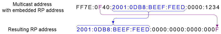
· Calculating the RP address
You can obtain the RP address from a multicast address by performing the following steps:
a. Copy the first "plen" bits of the "network prefix" to a zeroed 128-bit address structure.
b. Replace the last 4 bits with the contents of "RIID".
c. Set all other bits to 0.
Figure 33 shows an example for calculating the RP address. In this example, the RP address is embedded in FF7E:F40:2001:DB8:BEEF:FEED::1234.
Figure 33 Calculating the RP address
· Example
The network administrator wants to set up an RP on subnet 2001:DB8:BEEF:FEED::/64. The group addresses would be something like FF7x:y40:2001:DB8:BEEF:FEED::/96, and then their RP address would be 2001:DB8:BEEF:FEED::y. There are still 32 bits of multicast group IDs to assign.
If the network administrator wants to have more multicast group IDs that can be assigned, he can select a shorter unicast prefix, for example, Plen = 0x20 = 32 bits. In this case, the group addresses will be FF7X:Y20:2001:DB8::/64, and there are 64 bits for group IDs to be assigned. The RP address embedded is 2001:DB8::Y/32.
|
|
NOTE: X is any valid scope, and Y is any number from 1 to F. |
IPv6 SSM addresses
IPv6 Source-Specific Multicast (SSM) addresses use the format of Unicast-prefix-based IPv6 multicast addresses. The Plen and Network prefix fields are both set to 0. The IPv6 SSM address range is FF3X::/32 (X is any valid scope value).
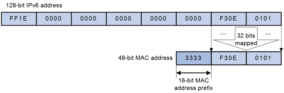
IPv6 multicast MAC addresses
The most significant 16 bits of an IPv6 multicast MAC address are 0x3333. The least significant 32 bits are mapped from the least significant 32 bits of an IPv6 multicast address. As shown in Figure 34, FF1E::F30E:101 is mapped to 33-33-F3-0E-01-01.
Figure 34 IPv6-to-MAC address mapping
IPv6 multicast protocols
IPv6 supports the following multicast protocols:
· Multicast Listener Discovery (MLD)
· MLD snooping.
· IPv6 Protocol Independent Multicast (IPv6 PIM)
· IPv6 Multicast BGP (IPv6 MBGP)
Multicast group management protocol
MLD is based on the Internet Group Management Protocol (IGMP). MLD has two versions: MLDv1 (derived from IGMPv2) and MLDv2 (derived from IGMPv3).
IGMP uses messages with the IP protocol number as 2. MLD uses the following ICMPv6 messages with the IP protocol number as 58:
· MLD query messages (type 130)
· MLDv1 listener report messages (type 131)
· MLDv1 done messages(type 132)
· MLDv2 listener report messages (type 143)
MLD behaves exactly the same as IGMP except that it uses different message formats.
Multicast routing protocols
IPv6 PIM supports the following modes:
· IPv6 Protocol Independent Multicast-Dense Mode (IPv6 PIM-DM)
· IPv6 Protocol Independent Multicast-Sparse Mode (IPv6 PIM-SM)
· IPv6 Protocol Independent Multicast Source-Specific Multicast (IPv6 PIM-SSM)
· IPv6 Bidirectional Protocol Independent Multicast (IPv6 BIDIR-PIM)
When sending the following protocol messages, IPv6 PIM uses the link local address of the sending interface as the source IPv6 address:
· Hello messages
· Join or prune messages
· Graft-ack messages
· State refresh messages
· Assert messages
· Bootstrap messages
· Graft messages
When sending the following protocol messages, IPv6 PIM uses the global unicast address of the sending interface as the source IPv6 address:
· Register messages
· Register-stop messages
· C-RP advertisement messages
IPv6 multicast does not support MSDP. To receive multicast packets from other IPv6 PIM domains, use either of the following methods:
· Obtain multicast source addresses of other IPv6 PIM domains by using other methods (such as advertisements) and use IPv6 PIM-SSM join the related multicast groups.
· Use the embedded RP mechanism to obtain multicast source addresses of other IPv6 PIM domains and join the RPs of other IPv6 PIM domains.
To deliver IPv6 multicast information between two ASs, use MBGP.
Layer 2 multicast protocols
· MLD snooping
MLD snooping is similar to IGMP snooping.
· IPv6 PIM snooping
IPv6 PIM snooping is similar to PIM snooping.
· Multicast VLAN
Multicast VLAN for IPv4 is the same as that for IPv6.
Network security
Dual-Stack authentication
Overview
Dual-stack users exist before the network completely transits from IPv4 to IPv6. If the network is configured with IPoE Web or portal authentication only for one IP stack, dual-stack users can access network resources only of this IP stack, which fails to satisfy the needs of the users. If the network is configured with IPoE Web or portal authentication for both the IP stacks, dual-stack users must pass IPoE Web or portal authentication of both IP stacks before they can access the network resources, which complicates the login process of the users.
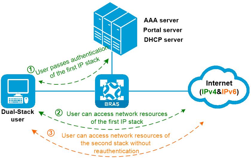
To resolve this issue, IPoE Web and portal dual-stack authentication are introduced. With the IPoE Web or portal dual-stack feature enabled, dual-stack portal users can access both IPv4 and IPv6 network resources after they pass IPv4 or IPv6 IPoE Web or portal authentication and come online.
Figure 35 Dual-Stack authentication
Benefits of IPoE Web or portal dual-stack authentication for IPv6 networks:
· Enhancing the user experience for dual-stack users
· Reducing the authentication pressure of the AAA server and Portal server.
· Simplifying network management and maintenance for the administrator.
Support of IPoE Web authentication for dual stack
The following describes the mechanism of IPoE Web dual-stack authentication:
1. After an IPoE Web user passes portal authentication of one IP stack (the first stack, for example, IPv4) after entering the username and password on the authentication page, the user can access network resources of this IP stack.
2. The device records the user's MAC address, username, authentication state, and other information.
3. Upon receiving a packet of the other IP stack (the second stack, for example, IPv6) from the user, the device compares the source MAC address with that for the user recorded by the device.
¡ If the MAC addresses are the same, the device allows the user to access network resources of the second stack without reauthentication.
¡ If the MAC addresses are different, the user needs to perform IPoE Web authentication of the second stack.
IPoE Web dual-stack authentication can be applied to the following scenarios:
· Dynamic dual-stack user authentication—Dual-stack users can come online after they pass authentication dynamically initiated by unclassified-IPv4 packets, unclassified-IPv6 packets, DHCPv4 packets, DHCPv6 packets, or ND RS packets. This type of authentication can be applied to mobile terminals with non-fixed IP addresses. For example, students access the campus network from mobile smart terminals.
· Static dual-stack user authentication—Dual-stack users can come online after they pass authentication statically initiated by IPv4 packets, IPv6 packets, ARP packets, NS packets, or NA packets. This type of authentication can be applied to terminals with static IP addresses. For example, students access the campus network from fixed network ports in the dormitory.
· Hybrid dual-stack user authentication—Dual-stack users can come online as both static users of one protocol stack and dynamic users of the other protocol stack. This type of authentication can be applied to the scenario when both terminals with fixed IP addresses and terminals with non-fixed IP addresses exist in the network. For example, if a campus is upgrading the campus network from IPv4 to IPv6, the static IPv4 and DHCPv6 address assignment method can be used, so that the IPv4 users can still access the network with static addresses and the IPv6 users can obtain dynamically assigned IPv6 addresses to access the network.
Support of portal authentication for dual stack
In a portal dual-stack authentication network, you can enable the portal dual-stack feature on an interface with portal authentication enabled as needed. Portal users on the interface can access both IPv4 and IPv6 network resources after passing one type (IPv4 or IPv6) of portal authentication
The following describes the mechanism of portal dual-stack authentication:
1. After a portal user passes portal authentication of one IP stack (the first stack, IPv4 or IPv6) after entering the username and password on the authentication page, the user can access network resources of this IP stack.
2. The device records the user's MAC address and IP address in the portal user entry for the user.
3. Upon receiving a packet of the other IP stack (the second stack, IPv6 or IPv4) from the user, the device compares the source MAC address with that in the portal user entry for the user.
¡ If the MAC addresses are the same, the device allows the user to access network resources of the second stack without reauthentication.
¡ If the MAC addresses are different, the user needs to perform portal authentication of the second stack.
|
|
IMPORTANT: The portal dual-stack feature takes effect on an interface only when both direct IPv4 portal authentication and direct IPv6 portal authentication are enabled on the interface. |
SAVI, SAVA, and SMA
Overview
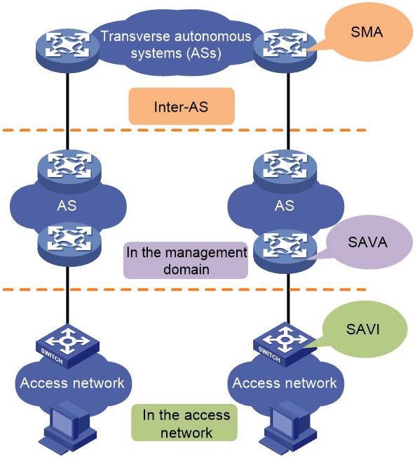
Source Address Validation checks the validity of the source IPv6 address of packets and discards packets with spoofed source IP addresses, thus improving the security of IPv6 networks. Source Address Validation Improvement (SAVI), Source Address Validation Architecture (SAVA), and State Machine Based Anti-Spoofing (SMA) are all technologies for source address validation. They can be deployed in specific network locations to meet different granularity of security needs.
· SAVI—Deployed in the access network. SAVI performs source address validation at the access level and provides host granularity source address validation, ensuring that hosts use only assigned valid IPv6 addresses.
· SAVA—Deployed on the border devices of the backbone network connecting to an access network. SAVA provides IPv6 prefix granularity protection in the management domain, so as to prevent core devices from source IPv6 address spoofing attacks initiated by illegal hosts.
· SMA—Deployed at the inter-AS level. SMA provides inter-AS granularity source address validation to prevent hosts and servers in the AS from source IPv6 address spoofing attacks initiated by illegal hosts.
Figure 36 Deployment locations of SAVI, SAVA, and SMA in networks
SAVI
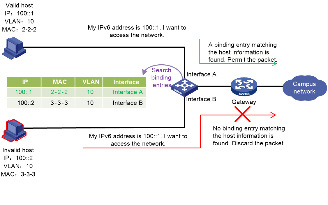
To prevent illegal attacks from DHCPv6 messages, ND messages, or IPv6 data packets with spoofed source addresses, you can enable SAVI on the device. The device creates binding entries that bind IP addresses and other information, and performs IPv6 source address validity check on packets based on the binding entries. Packets passing the validity check are forwarded. Packets sourced from an invalid address are dropped.
SAVI implements the validity check in combination with the DHCPv6 snooping, ND snooping, and IP source guard features.
Figure 37 SAVI mechanism
SAVA
SAVA checks the validity of the source IPv6 address of packets based on routing information to prevent source IPv6 address spoofing attacks. SAVA is typically deployed on the border devices of the backbone network connecting to an access network. With SAVA enabled on an interface connecting to the access network, the device creates SAVA entries for all user prefixes in the access network. Upon receiving an IPv6 packet on the interface, the device searches for a SAVA entry that contains the source IPv6 address and the receiving interface. If a match is found, the device considers the source IPv6 address as valid and forwards the packet. If no match is found, the device considers the source IPv6 address as invalid and discards the packet.
As shown in Figure 38, the creation process of SAVA entries (for example, on Border Device B) are as follows:
1. Border Devices A and B obtain user prefix information from locally learned routes reaching the access network, including direct routes, static routes, and dynamic routes for the interfaces connecting to the access network. (Static routes are used in this example.)
2. Device A adds a specified tag to the locally learned route reaching the access network, and redistributes the route to other border devices in the backbone network through a dynamic routing protocol.
3. Device B learns the route with the tag distributed by Device A through the dynamic routing protocol. If the tag in the route is the same as the tag configured for synchronizing remote routes, Device B obtains the valid user prefix information learned by Device A from the route for SAVA entry creation.
4. Device B creates SAVA entries bound to the SAVA-enabled interface based on valid user prefix information obtained from the local route and the synchronized remote route. A SAVA entry includes a prefix, prefix length, and binding interface.
Figure 38 SAVA entry creation process
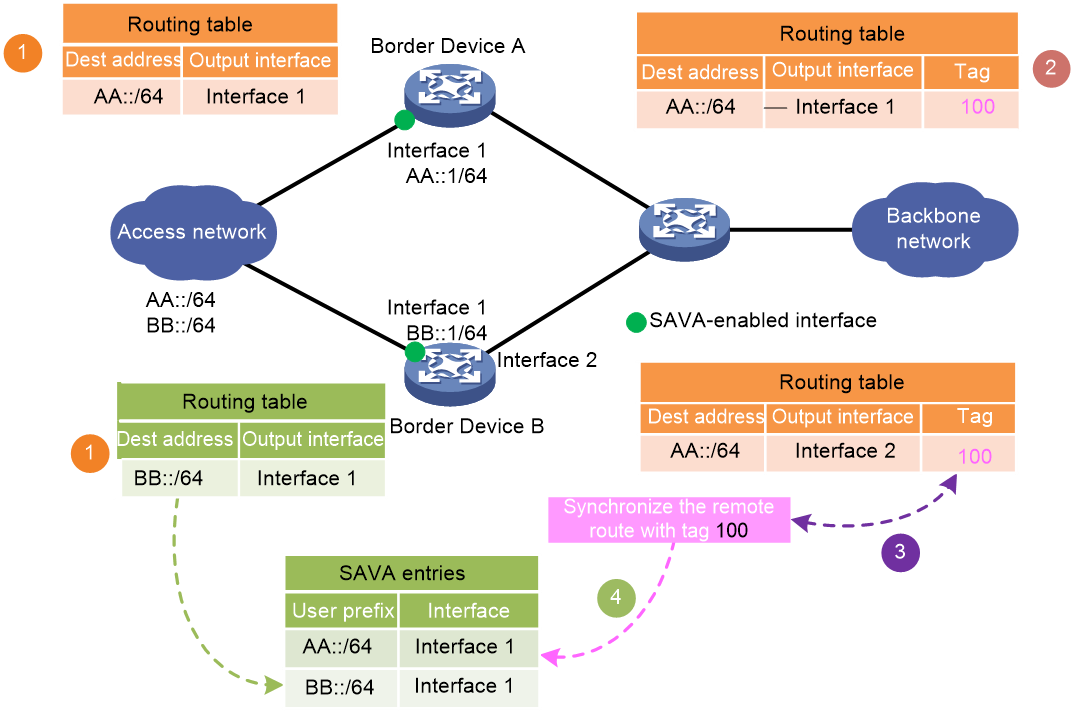
SMA
SMA prevents IPv6 spoofing attacks between autonomous systems by verifying source IPv6 addresses.
SMA network
As shown in Figure 39, an SMA network mainly contains the following components: AS Control Server (ACS) and AS Edge Router (AER).
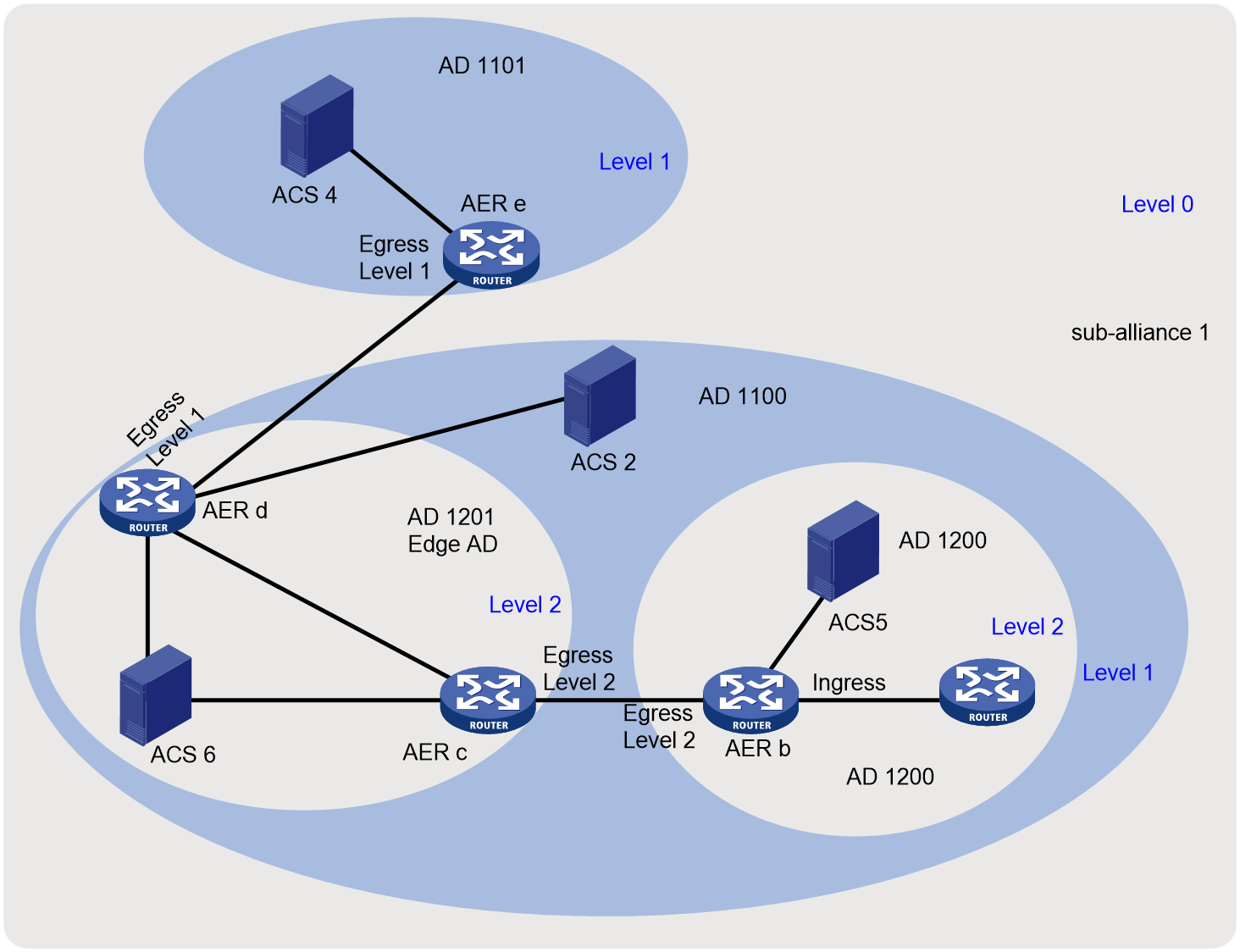
· Sub-trust alliance (hereinafter referred to as sub-alliance)—A group of ADs that trust each other. It is identified by a sub-alliance ID.
· Trust alliance (hereinafter referred to as alliance)—Collection of all ADs in the SMA system.
· Address domain (AD)—A group of IP address ranges managed by the same organization. It is the management object of a sub-alliance and is identified by an AD ID (AD 11.1, AD 1200, and AD 1201 for example). You can divide ADs in the same sub-alliance into a maximum of four levels to form a hierarchy structure. Smaller the level number, higher the level. For example, create level 0 for a city, create level 1 for an institution in the city, and create level 2 for a building or department of the institution. ADs contain the following types:
¡ Edge AD—An AD that connects the local level to another level, for example, AD 1201 in the figure.
¡ Non-edge AD.
If you create ADs of a lower level in an AD, for example, a level-1 AD in the level-0 AD, all devices (except for ACSs) in the original AD must be added to an AD of the lower level. As shown in Figure 39, all devices in the level-0 AD are in a level-1 AD.
· AS Control Server (ACS)—Required in each AD at every level. An ACS performs the following tasks:
¡ Exchanges IPv6 prefix and state machine information with ACSs of other sub-alliances in the same alliance.
¡ Sends alliance mapping, IPv6 prefix, and tag information to AERs of the local AD.
· AS Edge Router (AER)—Receives IPv6 prefix and tag information notified by ACSs and forwards packets between ADs. An AER can provide services for multiple ACSs at different levels. An AER has the following types of interfaces:
¡ Ingress interface—Connected to an SMA-disabled router in the local AD.
¡ Egress interface—Connected to an AER in another AD.
|
|
NOTE: · For security purposes, you can configure the ACSs to establish SSL links with each other and AERs. · The device can operate only as an AER. |
SMA processes for packets
SMA provides inter-AD IPv6 source address validation. It enforces source address validity on AERs. An AER validates source IPv6 addresses of packets between the local AD and other ADs in the same trust alliance.
An AER processes a received packet as follows:
1. Examine the interface type.
¡ If the interface is the ingress interface, the AER proceeds to step 2.
¡ If the interface is the egress interface, the AER proceeds to step 3.
2. Examine whether the source IPv6 prefix is a valid IPv6 prefix of the local AD.
¡ If yes, the AER forwards the packet based on the IPv6 routing table.
¡ If no, the AER discards the packet.
3. Examine whether the destination IPv6 prefix is a valid IPv6 prefix of the sub-alliance.
¡ If yes, the AER proceeds to the next step.
¡ If no, the AER forwards the packet based on the IPv6 routing table.
4. Examine whether the destination IPv6 address is a valid address of the local AD or an AD at a lower level in the local AD.
¡ If yes, the AER proceeds to the next step.
¡ If no, the AER forwards the packet based on the IPv6 routing table.
5. Examine the validity of the sub-alliance tag.
¡ If the tag is valid, the AER proceeds to the next step.
¡ If the tag is invalid, the AER discards the packet.
6. Examine whether the packet is destined to an AD at a lower level in the local AD.
¡ If yes, the AER replaces the packet tag with the tag of the lower-level AD, and then forwards the packet based on the IPv6 routing table.
The lower-level AER processes the packet in the same way.
¡ If no, the AER removes the packet tag, and then forwards the packet based on the IPv6 routing table.
Figure 40 Incoming packet processing workflow
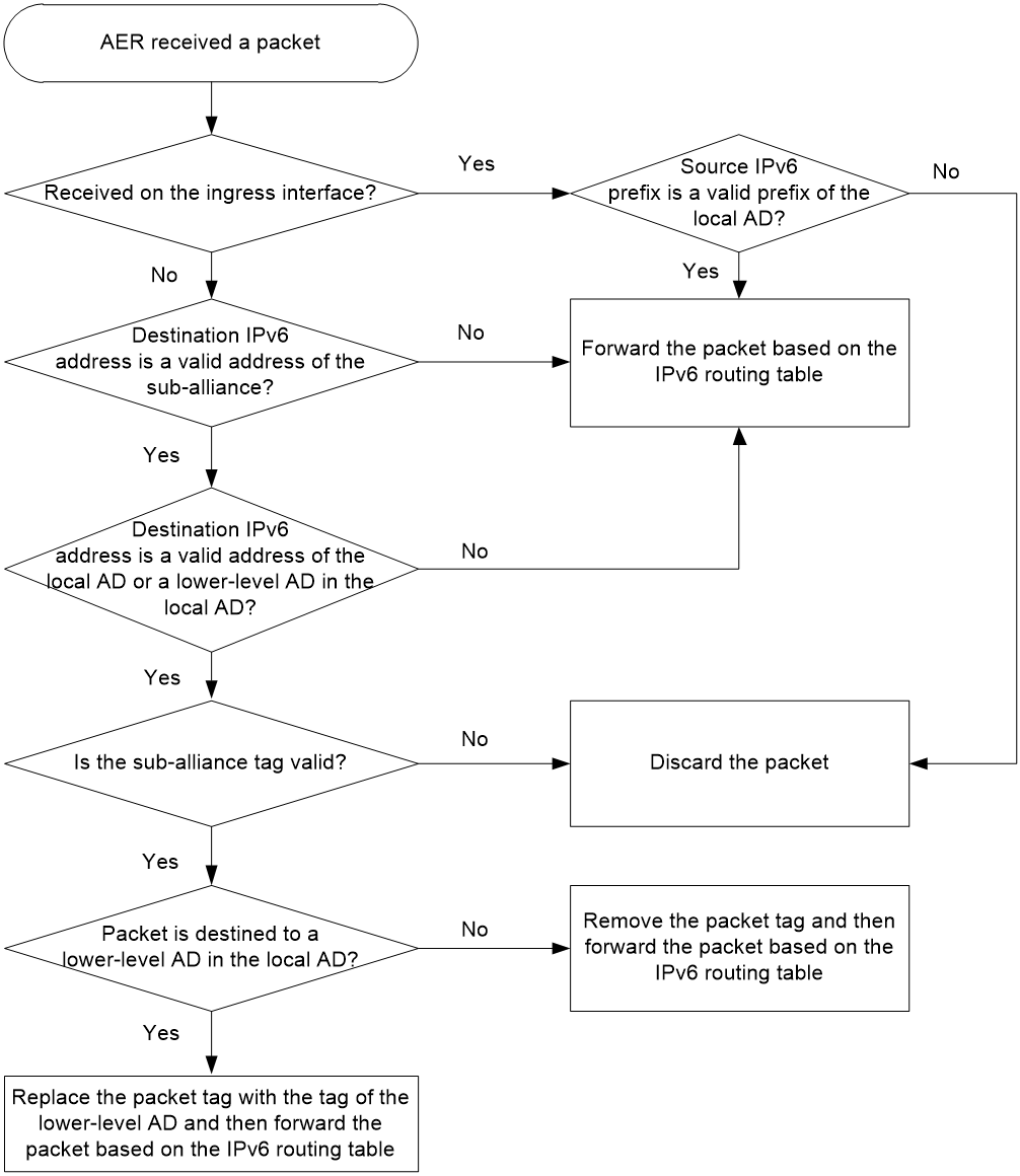
An AER processes an outgoing packet as follows:
1. Examine whether the source IPv6 prefix is a valid prefix of the local AD.
¡ If yes, the AER adds a tag to the packet and then forwards the packet based on the IPv6 routing table.
¡ If no, the AER proceeds to the next step.
2. Examine whether the packet is destined to a higher-level AD of the local AD.
¡ If yes, the AER proceeds to the next step.
¡ If no, the AER forwards the packet based on the IPv6 routing table.
3. Examine the validity of the sub-alliance tag.
¡ If yes, the AER replaces the tag with the higher-level AD tag and then forwards the packet based on the IPv6 routing table.
¡ If no, the AER discards the packet.
Figure 41 Outgoing packet processing workflow
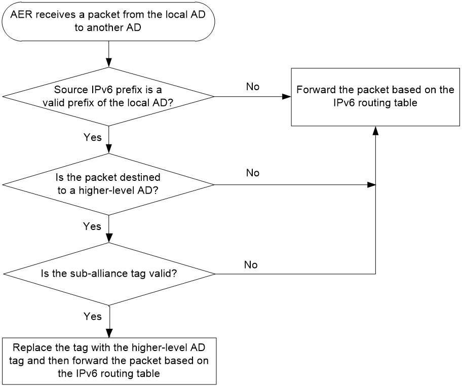
Microsegmentation
About microsegmentation
With the growth of data centers, east-west traffic within a data center keeps increasing and becomes the majority of traffic in data centers. Network administrators need to perform security protection on east-west traffic. If all the east-west traffic in a data center bypasses the traditional centralized firewall, the firewall will become a bottleneck to performance increase and flexible scaling for the data center.
Microsegmentation groups network endpoints such as servers and virtual machines in a data center network and various user endpoints in a campus network. With inter-group policies, you can secure and control the communication between network endpoints belonging to different groups. This mechanism provides fine control granularity and conserves ACL resources.
Benefits
Microsegmentation offers the following benefits:
· Distributed security implementation—East-west traffic is not forwarded centrally to the firewall for security isolation, which saves bandwidth and prevents the firewall from becoming a bottleneck in forwarding.
· Fine and flexible isolation—Microsegmentation can implement isolation within a subnet based on disperse IP addresses or IP address ranges.
· ACL resource conservation—Microsegmentation uses fewer AC resources than typical ACL-based security control.
As shown in Figure 1, to isolate Host A and Host B from each other, you can use the following methods:
¡ ACL—Configure two ACLs, each of which uses a 256-bit ACL resource.
¡ Microsegmentation—Configure two microsegments that match traffic by the 16-bit microsegment ID. The microsegments each use a 32-bit ACL resource.
Figure 42 ACL resource conservation
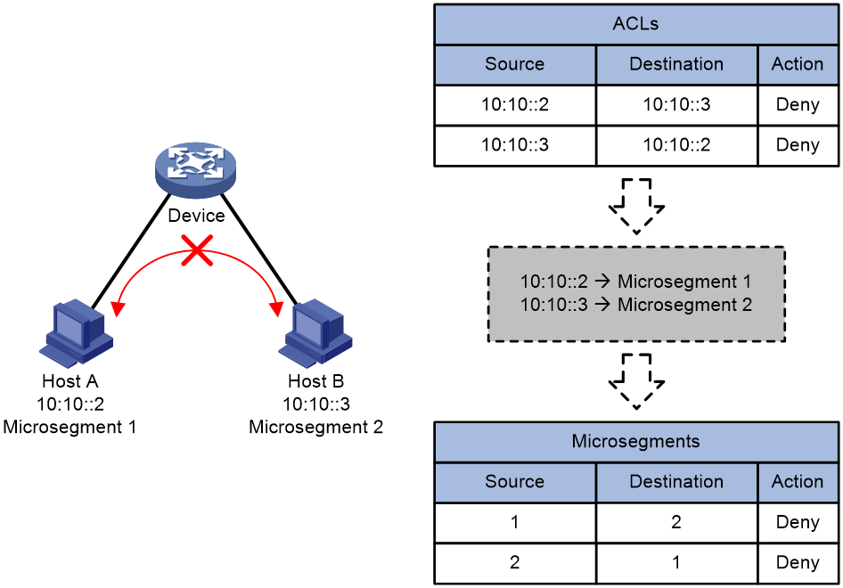
Mechanisms
Microsegmentation uses the following concepts:
· Microsegment—A group of network endpoints. Each microsegment has a globally unique ID. You can assign endpoints to microsegments based on IP addresses, IP ranges, or MAC addresses. Endpoints in the same microsegment can communicate with one another.
· Group-based policy (GBP)—A microsegment-based traffic control policy. GBPs control communication between microsegments. GBPs can be implemented by using packet filtering, QoS policies using the MQC approach, or PBR.
Microsegmentation limits communication on the source-side device. To configure microsegmentation, perform the following tasks on the source-side device:
1. Assign network endpoints to microsegments based on the application scenario and deployment method. Microsegment types are static IP microsegment, static AC microsegment, authentication and authorization microsegment, and route advertisement microsegment.
2. Create ACLs based on microsegment IDs.
3. Configure GBPs to control communication between microsegments by using the created ACLs.
When the source-side device receives packets, it checks the ACLs for a match based on the microsegment ID and applies the GBP associated with the matching ACL to the packets. The bandwidth of the transport network is saved if the packets are dropped according to the GBP.
Figure 43 Source-side traffic control

Typical applications
Microsegmentation can be applied to an EVPN VXLAN network in a data center through manual configuration or SDN controller deployment.
As shown in Figure 3, microsegmentation is configured as follows:
· For east-west traffic, configure the following static IP microsegments on Leaf 1 and Leaf 2:
¡ Assign 192:168:1::0/120 to microsegment 1.
¡ Assign 192:168:2::0/120 to microsegment 2.
¡ Assign 192:168:3::0/120 to microsegment 3.
· For north-south traffic, configure the following static IP microsegments on Leaf 1 and Leaf 2:
¡ Assign 0::0/0 to microsegment 4 for the border device to advertise default routes destined for the Internet and firewall through BGP.
¡ Assign 192:168:20::0/120 to microsegment 5 for the border device to advertise network routes destined for the OA network through BGP.
· Configure ACLs and GBPs as needed to control communication between segments.
Figure 44 Microsegments in an EVPN VXLAN network
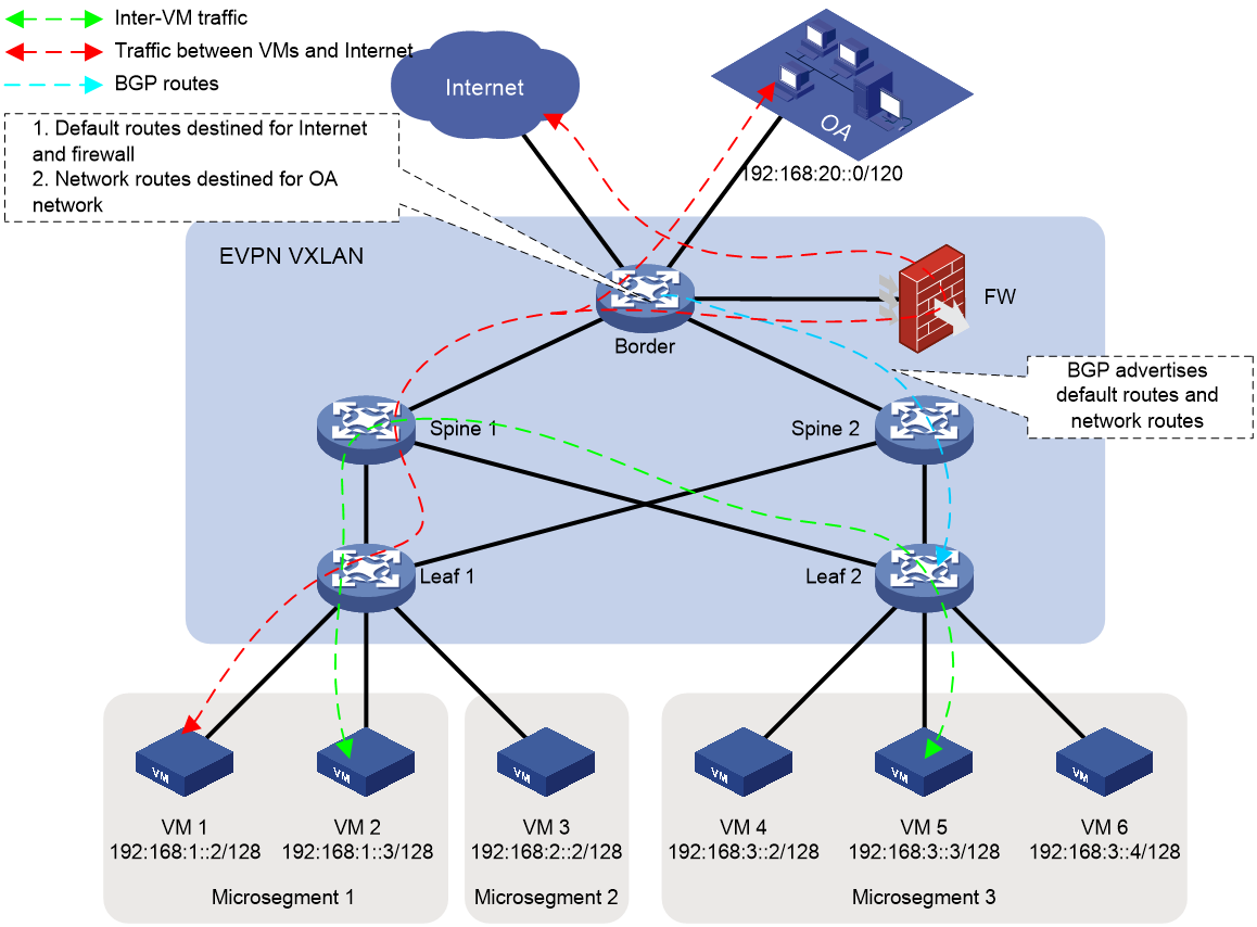
IPv6-based VXLAN and EVPN VXLAN
Virtual eXtensible LAN (VXLAN) is a MAC-in-UDP technology that provides Layer 2 and Layer 3 connectivity between distant network sites across an IP network. VXLANs use manually established VXLAN tunnels.
Ethernet Virtual Private Network (EVPN) is a Layer 2 VPN technology that provides both Layer 2 and Layer 3 connectivity between distant network sites across an IP network. EVPN uses MP-BGP to advertise EVPN routes in the control plane and VXLAN to forward traffic in the data plane. EVPN VXLAN sets up VXLAN tunnels automatically based on EVPN routes.
A VXLAN is a virtual Layer 2 network (known as the overlay network) built on top of an existing physical Layer 3 network (known as the underlay network). The overlay network encapsulates inter-site Layer 2 frames into VXLAN packets and forwards the packets to the destination along the Layer 3 forwarding paths provided by the underlay network. The underlay network is transparent to tenants, and geographically dispersed sites of a tenant are merged into one Layer 2 network.
The site networks and the undelay network can be IPv6 networks.
Figure 45 VXLAN and EVPN VXLAN network model
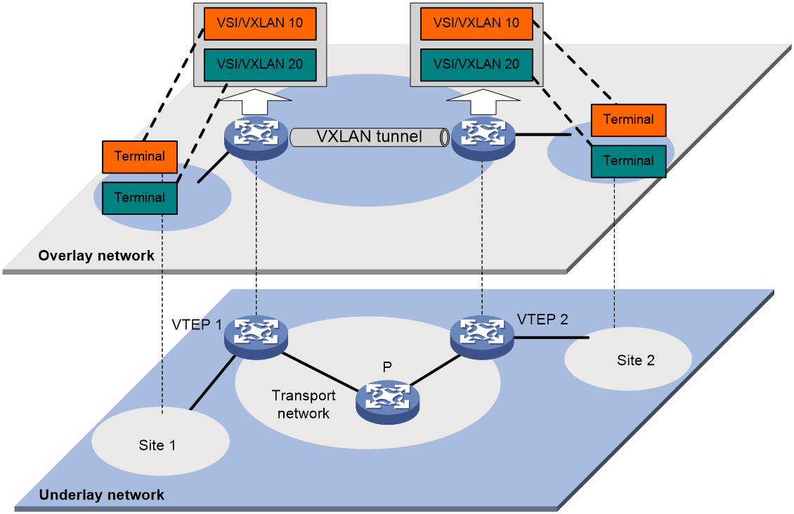
The transport edge devices assign user endpoints to isolated VXLANs uniquely identified by 24-bit VXLAN IDs, and then forward traffic between sites for user endpoints by using VXLAN tunnels. Supported user endpoints include PCs, wireless terminals, and VMs on servers.
The transport edge devices are VXLAN tunnel endpoints (VTEP). The VTEP implementation of the device uses ACs, VSIs, and VXLAN tunnels to provide VXLAN services.
· VSI—A virtual switch instance is a virtual Layer 2 switched domain. Each VSI provides switching services only for one VXLAN. VSIs learn MAC addresses and forward frames independently of one another. VMs in different sites have Layer 2 connectivity if they are in the same VXLAN.
· Attachment circuit (AC)—An AC is a physical or virtual link that connects a VTEP to a local site. Typically, ACs are site-facing Layer 3 interfaces or Ethernet service instances that are associated with the VSI of a VXLAN. Traffic received from an AC is assigned to the VSI associated with the AC. Ethernet service instances are created on site-facing Layer 2 interfaces. An Ethernet service instance matches a list of custom VLANs by using a frame match criterion.
· VXLAN tunnel—Logical point-to-point tunnels between VTEPs over the transport network. Each VXLAN tunnel can trunk multiple VXLANs.
VTEPs encapsulate VXLAN traffic in the VXLAN, outer UDP, and outer IP headers. The devices in the transport network forward VXLAN traffic only based on the outer IP header.
IPv6 transition technologies
IPv6 transition technologies enable communication between IPv4 and IPv6 networks. Commonly used IPv6 transition technologies include dual stack, tunneling, AFT, and 6PE.
Dual stack
Dual stack is the most direct transition approach. A network node that supports both IPv4 and IPv6 is a dual-stack node. A dual-stack node configured with an IPv4 address and an IPv6 address can forward both IPv4 and IPv6 packets. An application that supports both IPv4 and IPv6 prefers IPv6 at the network layer.
Dual stack is the basis of all transition technologies. This technology provides the following benefits:
· The technology is mature. You do not need to separately deploy network settings to different types of users.
· The cost is relatively low, which protects user investment.
· Transition from IPv4 to IPv6 is transparent by preferentially using the IPv6 network to gradually increase the volume of IPv6 traffic.
· This technology provides inter-service fast visits with good interoperability and reduces address translation loss caused by inter-protocol access.
However, dual stack has the following limitations:
· The transformation workload is heavy. You need to complete IPv4 and IPv6 deployment for the whole network. Configuration management is also complex.
· The requirements for device performance are high. It is necessary to consider the issue of hardware resource entry sharing.
· Dual stack does not solve the IPv4 address depletion issue because each dual-stack node must have a globally unique IPv4 address and IPv6 address.
Tunneling
Tunneling uses one network protocol to encapsulate the packets of another network protocol and transfers them over the network.
IPv6 over IPv4 tunneling and IPv4 over IPv6 tunneling are used to connect isolated IPv6 or IPv4 sites and solve the intercommunication issues of IPv4 and IPv6 networks.
· IPv6 over IPv4 tunneling—As shown in Figure 42, this technology encapsulates an IPv6 packet into an IPv4 packet so that the IPv6 hosts can communicate with each other over the IPv4 network. IPv6 over IPv4 tunnels include IPv6 over IPv4 manual tunnels, automatic IPv4-compatible IPv6 tunnels, 6to4 tunnels, ISATAP tunnels, and 6RD tunnels.
Figure 46 IPv6 over IPv4 tunnel
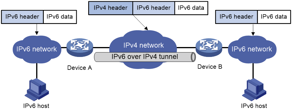
· IPv4 over IPv6 tunneling—As shown in Figure 43, this technology encapsulates an IPv4 packet into an IPv6 packet so that the IPv4 hosts can communicate with each other over the IPv6 network.
Figure 47 IPv4 over IPv6 tunnel

Tunneling technologies provide intercommunication for multiple data center networks and site networks over the backbone network. The intercommunication is transparent to the backbone network. Typically, the technologies are used in a WAN.
Tunneling technologies provide the following benefits:
· You hardly need to adjust the original network topology and routes to provide service access for a small number of IPv6 sites in a short time.
· You only need to upgrade the devices at the edge of the IPv4 and IPv6 networks. The transformation scope is small, the cost is low, and the tunneling technologies are mature.
However, tunneling technologies have the following limitations:
· The technologies cannot provide inter-application access across protocols. For inter-application access across protocols, the technologies must be used in conjunction with protocol translation technologies.
· Tunneling technologies are implemented on software. In a large-scale network, these technologies consume a large amount of device CPU and memory resources. Device performance becomes a bottleneck to limit the network scale.
· O&M workload is heavy and interfaces are ambiguous. Large scale deployment is not recommended.
AFT
About AFT
Address Family Translation (AFT) translates an IP address of one address family into an IP address of the other address family. It enables an IPv4 network and an IPv6 network to communicate with each other.
AFT is configured on a device deployed at the boundary of an IPv4 network and IPv6 network. All address family translation operations are performed on that device. The operations are transparent to users in the IPv4 and IPv6 networks. An IPv4 host and an IPv6 host can communicate with each other without changing the existing configuration.
When nodes cannot be upgraded to have IPv6 capabilities, deploy an AFT device at the boundary of the IPv4 and IPv6 networks.
Prefix translation
NAT64 prefix translation
NAT64 prefix is an IPv6 address prefix used to construct an IPv6 address representing an IPv4 node in an IPv6 network. The IPv6 hosts do not use a constructed IPv6 address as their real IP address. The length of a NAT64 prefix can be 32, 40, 48, 56, 64, or 96.
As shown in Figure 44, the construction methods vary depending on the NAT64 prefix length. Bits 64 through 71 in the constructed IPv6 address are reserved bits.
· If the prefix length is 32, 64, or 96 bits, the IPv4 address contained in the IPv6 address will be intact.
· If the prefix length is 40, 48, or 56 bits, the IPv4 address contained in the IPv6 address will be divided into two parts by bits 64 through 71.
Figure 48 IPv6 address construction with NAT64 prefix and IPv4 address

AFT constructs addresses for IPv4 nodes in an IPv6 network, as shown in Table 10.
Table 10 Example for IPv6 address construction with NAT64 prefix and IPv4 address
|
IPv6 prefix |
IPv4 address |
IPv6 address that includes an IPv4 address |
|
2001:db8::/32 |
192.0.2.33 |
2001:db8:c000:221:: |
|
2001:db8:100::/40 |
192.0.2.33 |
2001:db8:1c0:2:21:: |
|
2001:db8:122::/48 |
192.0.2.33 |
2001:db8:122:c000:2:2100:: |
|
2001:db8:122:300::/56 |
192.0.2.33 |
2001:db8:122:3c0:0:221:: |
|
2001:db8:122:344::/64 |
192.0.2.33 |
2001:db8:122:344:c0:2:2100:: |
|
2001:db8:122:344::/96 |
192.0.2.33 |
2001:db8:122:344::192.0.2.33 |
IVI prefix translation
An IVI prefix is a 32-bit IPv6 address prefix. An IVI address is the IPv6 address that an IPv6 node uses. As shown in Figure 45, the IVI address includes an IVI prefix and an IPv4 address.
![]()
AFT uses an IVI prefix for IPv6-to-IPv4 source address translation. If a source IPv6 address matches the IVI prefix, AFT translates it to the embedded IPv4 address.
General prefix translation
A general prefix is an IPv6 address prefix used to construct an IPv6 address representing an IPv4 node in an IPv6 network. The length of a general prefix can be 32, 40, 48, 56, 64, or 96.
As shown in Figure 46, a general prefix based IPv6 address does not have bits 64 through 71 reserved as a NAT64 prefix based IPv6 address does. An IPv4 address is embedded as a whole into an IPv6 address.
Figure 50 General prefix based IPv6 address format
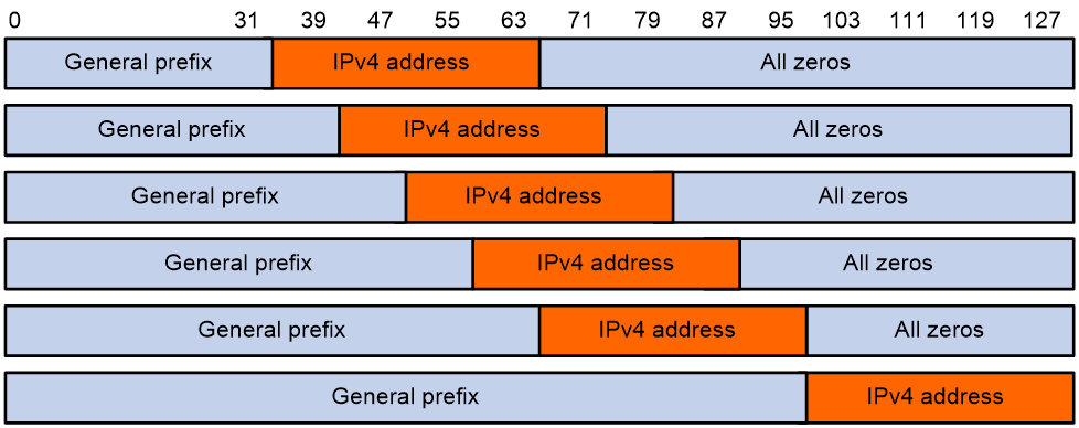
Benefits and limitations
AFT provides the following benefits:
· You only need to upgrade the devices at the edge of the IPv4 and IPv6 networks. The network transformation scope is small. You can upgrade IPv4 to IPv6 in a short time.
· IPv6 transformation and upgrade is not required for service systems.
AFT has the following limitations:
· AFT is strongly coupled with services. For some protocols, AFT not only translates the source and destination addresses in the packet header, but also needs to cooperate with an Application Level Gateway (ALG) to inspect the address information in the data payload at the application layer and translate the addresses. These operations increase the processing complexity. In addition, protocol information loss might occur.
· Equivalence of Internet nodes is broken.
· Source tracing is difficult.
6PE
IPv6 provider edge (6PE) is a transition technology that uses MPLS to connect sparsely populated IPv6 networks through an existing IPv4 backbone network. It is an efficient solution for ISP IPv4/MPLS networks to provide IPv6 traffic switching capability.
Figure 51 Network diagram for 6PE
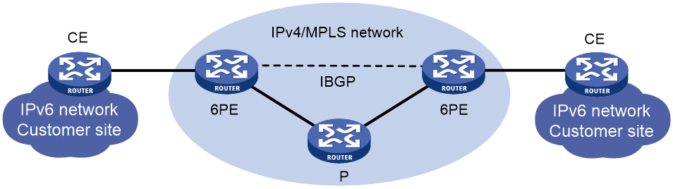
6PE mainly performs the following operations:
· 6PE assigns a label to IPv6 routing information received from a CE router, and sends the labeled IPv6 routing information to the peer 6PE device through an MP-BGP session. The peer 6PE device then forwards the IPv6 routing information to the attached customer site.
· 6PE provides tunnels over the IPv4 backbone so the IPv4 backbone can forward packets for IPv6 networks. The tunnels can be GRE tunnels, MPLS LSPs, or MPLS TE tunnels.
· Upon receiving an IPv6 packet, 6PE adds an inner tag (corresponding to the IPv6 packet) and then an outer tag (corresponding to the public network tunnel) to the IPv6 packet. Devices in the IPv4 backbone network forwards the packet based on the outer tag. When the peer 6PE device receives the packet, it removes the outer and inner tags and forwards the original IPv6 packet to the attached customer site.
With the help of 6PE, an IPv4 network service provider only needs to upgrade the devices deployed at the edge of the IPv4 and IPv6 networks for the devices to support both IPv4 and IPv6 stacks. In this way, the service provider can use the existing IPv4 or MPLS network to provide access services for isolated IPv6 users that are geographically dispersed.
6PE deployment requires less network transformation, but the deployment configuration is complex. It is not easy to maintain a 6PE network.
6vPE
6vPE is also called IPv6 MPLS L3VPN. Figure 48 shows a typical IPv6 MPLS L3VPN model. The service provider backbone in the IPv6 MPLS L3VPN model is an IPv4 network. IPv6 runs inside the VPNs and between CE and PE. IPv4 runs between PE and P. In this model, PEs must support both IPv4 and IPv6. The PE-CE interfaces of a PE run IPv6, and the PE-P interface of a PE runs IPv4.
When a PE receives an IPv6 route from a CE, it assigns a private network label to the route and uses a VPNv6 route to advertise the private network label and the IPv6 route to remote PEs. When the PE forwards IPv6 packets over the IPv4 backbone network, it adds the private network label to the IPv6 packets for the IPv4 network to transparently forward the IPv6 packets.
Figure 52 Network diagram for the IPv6 MPLS L3VPN model
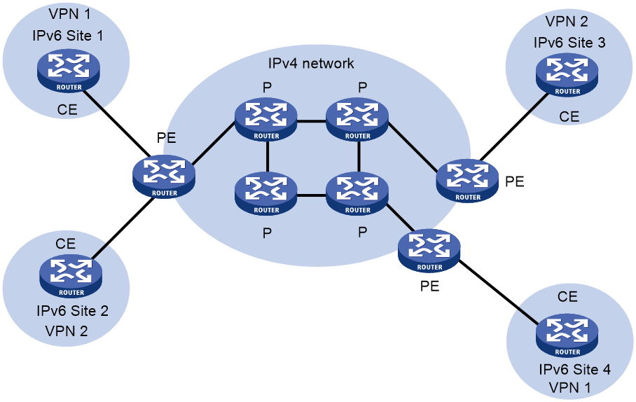
As shown in Figure 49, the IPv6 MPLS L3VPN packet forwarding procedure is as follows:
1. The PC at Site 1 sends an IPv6 packet destined for 2001:2::1, the PC at Site 2. CE 1 transmits the packet to PE 1.
2. Based on the inbound interface and destination address of the packet, PE 1 finds a matching entry from the routing table of the VPN instance, labels the packet with both a private network label (inner label) and a public network label (outer label), and forwards the packet out.
3. The MPLS backbone transmits the packet to PE 2 by outer label. The outer label is removed from the packet at the penultimate hop.
4. According to the inner label and destination address of the packet, PE 2 searches the routing table of the VPN instance to determine the outbound interface, and then forwards the packet out of the interface to CE 2.
5. CE 2 forwards the packet to the destination by IPv6 forwarding.
6vPE is used to connect isolated IPv6 sites over an IPv4 backbone network. This technology requires that the backbone network must support MPLS L3VPN. 6vPE network deployment is complex. In addition, it is hard to maintain a 6vPE network.
Figure 53 Network diagram for IPv6 MPLS L3VPN packet forwarding
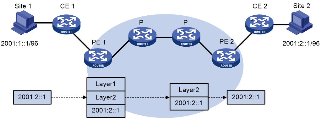
Enhanced IPv6: IPv6+
About IPv6+
IPv6+ is an intelligent IP technology for the 5G and cloud era. This technology enhances the IPv6 protocol by adding intelligent identification and control and gaining the characteristics of path programmability, rapid service delivery, automated O&M, quality visualization, SLA assurance, and application awareness.
IPv6+ is developed as follows:
· IPv6+1.0—Mainly SRv6 basic features, including TE, VPN, and FRR. These features are widely used.
· IPv6+2.0—Technological innovations that meet the new service and feature requirements in the 5G and cloud era, including but not limited to iFIT, BIER, network slicing, G-SRv6, service function chaining (SFC), and deterministic network (DetNet).
· IPv6+3.0—The focus is application-aware IPv6 networking (APN6). APN6 further enhances the seamless combination of network capabilities and service requirements on the basis of IPv6+2.0. Benefited from the path programmability characteristics of SRv6, APN6 adds application information such as application ID and network performance requirements to SRv6 packets. With the application information, the network can perceive applications and their requirements, so that it can provide the corresponding SLA assurance for the applications.
Currently, H3C supports the following IPv6+ technologies:
· IPv6 Segment Routing (SRv6) —Carrier technology for the next generation network. SRv6 is a key IPv6+ technology. This technology supports flexible path orchestration based on an IPv6 extension header. Currently, H3C supports SRv6 basic features, G-SRv6, and SFC.
· Network slicing—This technology divides a physical network into multiple logical networks for multiple services to share one network and service isolation.
· in-situ Flow Information Telemetry (iFIT)—Detection technology that directly measures network performance indexes. This technology uses gRPC to report detection results for network visualization.
· Bit Index Explicit Replication (BIER)—New technical architecture for multicast forwarding. This architecture supports IPv6 multicast forwarding, simplifies the network protocol, and provides excellent multicast service expansibility.
SRv6
SRv6 is a carrier technology for the next generation network. Based on IPv6 and source routing, this technology simplifies the traditional complex network protocol and provides application-level SLA assurance.
SRv6 has strong network programmability, and it is the basis of network automation. This technology can unify the data plane of network slices, which not only has the flexibility and strong programmability of IPv6, but also provides strong support for intelligent IP network slicing, DetNet, and SFC.
Basic concepts
SRv6 applies Segment Routing to an IPv6 network and uses IPv6 addresses as SIDs. SRv6 nodes forward packets according to the SID list encapsulated in the Segment Routing Header (SRH) of IPv6 packets. The SID list controls the packet forwarding path.
Benefits
SRv6 provides the following benefits:
· Simplified maintenance—You only need to control and maintain path information on the source node. Path maintenance is not required on other nodes.
· Intelligent control—Designed based on SDN architecture, SRv6 perfectly integrates applications and networks, which is a superb application driven network solution. All SRv6 forwarding paths, forwarding behaviors, and service types are controllable.
· Simple deployment—By extending IGP and BGP, SRv6 does not require MPLS labels. You do not need to deploy label distribution protocols. The SRv6 configuration is simple.
In an SRv6 network, you do not need to upgrade network devices in a large scale to deploy new services. In a data center or WAN, you only need to ensure that the network edge devices and specific network nodes support SRv6 and other devices support IPv6.
· Adaptable to 5G service requirements—With the development of 5G services, IPv4 addresses can no longer meet the network requirements of operators. To meet 5G service requirements, deploy SRv6 in the operator networks to configure all devices to forward traffic based on IPv6 addresses.
· Good scalability—SRv6 defines multiple types of SIDs. They have different functions and instruct different forwarding actions. You can use different types of SIDs to implement different VPN services. In addition, new types of SIDs can be defined as needed to meet new service requirements.
Basic forwarding mechanism
Figure 50 shows the simplified format of an SRv6 packet.
· IPv6 Destination Address—IPv6 packet destination address, also referred to as IPv6 DA. In a common IPv6 packet, the IPv6 DA is fixed. In an SRv6 packet, the IPv6 DA only identifies the next node of the current packet. When the SRv6 packet is forwarded to the next node, the IPv6 DA is changed.
· SRH(SL=n-1)<Segment List [0]=a, Segment List [1]=b, …, Segment List [n-1]=x>—SID list in the SRv6 packet. The values of the SL and Segment List fields determine the value of the IPv6 DA.
Figure 54 SRv6 packet simplified format
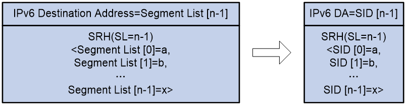
As shown in Figure 51, each time an SRv6 packet passes through an SRv6 node, the value for the SL field decreases by 1 and the IPv6 DA is changed.
· When the value for the SL field is n-1, the IPv6 DA is x (corresponding to SID [n-1]). The n parameter represents the number of segments in the forwarding path.
· When the value for the SL field becomes 1, the IPv6 DA is b (corresponding to SID [1]).
· When the value for the SL field becomes 0, the IPv6 DA is a (corresponding to SID [0]).
Figure 55 SRH processing procedure
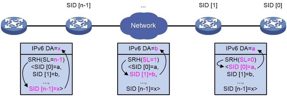
SRv6 packet forwarding modes
SRv6 supports the following forwarding modes:
· SRv6 BE—In this mode, an SRv6 node uses an IGP to advertise a locator segment. The nodes in the SRv6 network calculate the optimal route to the locator segment according to the shortest path first algorithm. The path of the optimal route is called an SRv6 BE path. When the BGP routes in the public network or a VPN instance are recursed to the SRv6 BE path on an SRv6 node, the SRv6 node can steer the public network traffic or VPN traffic to the SRv6 BE path.
· SRv6 TE—In this mode, the ingress node uses different methods to steer public network traffic or VPN traffic to the forwarding path of an SRv6 TE policy. The forwarding path of the SRv6 TE policy is called an SRv6 TE path.
G-SRv6
Background
In an SRv6 TE policy scenario, the administrator needs to add the 128-bit SRv6 SIDs of SRv6 nodes on the packet forwarding path into the SID list of the SRv6 TE policy. If the packet forwarding path is long, a large number of SRv6 SIDs will be added to the SID list of the SRv6 TE policy. This greatly increases the size of the SRv6 packet header, resulting in low device forwarding efficiency and reduced chip processing speed. The situation might be worse in a scenario that spans across multiple ASs where a much greater number of end-to-end SRv6 SIDs exist.
Generalized SRv6 (G-SRv6) encapsulates shorter SRv6 SIDs (G-SIDs) in the segment list of SRH by compressing the 128-bit SRv6 SIDs. This reduces the size of the SRv6 packet header and improves the efficiency for forwarding SRv6 packets. In addition, G-SRv6 supports both 128-bit SRv6 SIDs and G-SIDs in a segment list.
About G-SRv6
Typically, an address space is reserved for SRv6 SID allocation in an SRv6 subnet. This address space is called an SID space. In the SRv6 subnet, all SIDs are allocated from the SID space. The SIDs have the same prefix (common prefix). The SID common prefix is redundant information in the SRH.
G-SRv6 removes the common prefix and carries only the variable portion of SRv6 SIDs (G-SIDs) in the segment list, effectively reducing the SRv6 packet header size. To forward a packet according to routing table lookup, SRv6 replaces the destination IP address of the packet with the combination of the G-SID and common prefix in the segment list of the SRH.
With the compression efficiency and network scale taken into consideration, the ideal length of SRv6 SIDs is 32 bits after compression through G-SRv6
G-SID format
As shown in Figure 52, the locator portion of an SRv6 SID contains the Common Prefix and Node ID portions. The Common Prefix portion represents the address of the common prefix. The Node ID portion identifies a node. G-SRv6 can compress all SIDs with the same common prefix into 32-bit G-SIDs. A G-SID contains the Node ID and Function portions of a 128-bit SRv6 SID. A 128-bit SRv6 SID is formed by the Common Prefix portion, a 32-bit G-SID, and the 0 (Args&MBZ) portion.
Figure 56 Compressible SRv6 SID
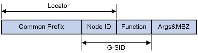
G-SRv6 packet format
As shown in Figure 53, G-SRv6 can encapsulate both G-SIDs and 128-bit SRv6 SIDs in the segment list of the SRH. It needs to encapsulate four G-SIDs in a group to the original location of a 128-bit SRv6 SID. If the location contains fewer than four G-SIDs (less than 128 bits), G-SRv6 pads the remaining bits with 0s. Multiple consecutive G-SIDs form a compressed path, called a G-SID list. A G-SID list can contain one or more groups of G-SIDs.
Figure 57 G-SRv6 packet format
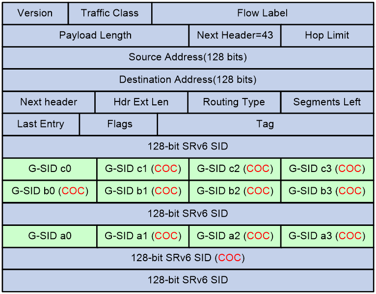
|
|
NOTE: If the SRv6 SID of the next node requires compression, the routing protocol adds the Continue of Compression (COC) flag to the advertised SRv6 SID of the local node. The COC flag indicates that the next SRv6 SID is a G-SID. A COC flag only identifies the forwarding behavior of an SRv6 SID, and is not actually carried in the packet. The COC flags in Figure 53 are for illustration purposes only. |
The G-SIDs in the segment list are arranged as follows:
· The SRv6 SID before the G-SID list is a 128-bit SRv6 SID with the COC flag, indicating that the next SID is a 32-bit G-SID.
· Except the last G-SID, all G-SIDs in the G-SID list must carry the COC flag to indicate that the next SID is a 32-bit G-SID.
· The last G-SID in the G-SID list must be a 32-bit G-SID without the COC flag, indicating that the next SID is a 128-bit SRv6 SID.
· The next SRv6 SID after the G-SID list is a 128-bit SRv6 SID that can carry the COC flag or does not carry the COC flag.
Calculating the destination address with G-SID
As shown in Figure 54, G-SRv6 combines the G-SID and Common Prefix in the segment list to form a new destination address.
· Common Prefix—Common prefix address manually configured by the administrator.
· G-SID—Compressed 32-bit SID obtained from the SRH.
· SID Index (SI)—Index that identifies a G-SID in a group of G-SIDs. This field is the least significant two bits of the destination IPv6 address. The value range is 0 to 3. The SI value decreases by 1 at each node that performs SID compression. If the SI value becomes 0, the SL value decreases by 1. In a group of G-SIDs in the segment list, the G-SIDs are arranged from left to right based on SI values. The SI value is 0 for the leftmost G-SID, and is 3 for the rightmost G-SID.
· 0—If the total length of the Common Prefix, G-SID, and SI portions is less than 128 bits, the deficient bits are padded with 0s before the SI portion.
Figure 58 Destination address calculated with G-SID
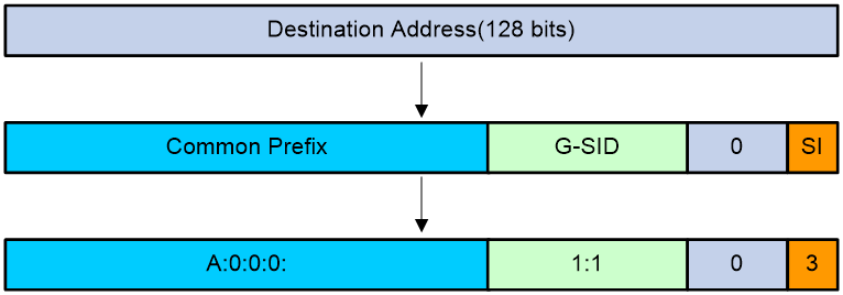
Suppose the following conditions exist:
· The Common Prefix deployed on the SRv6 node is A:0:0:0::/64.
· The G-SID in the SRv6 packet is 1:1.
· The SI value associated with the G-SID is 3.
Based on the previous conditions, the device calculates the destination address as A:0:0:0:1:1::3.
Upon receiving the G-SRv6 packet, the SRv6 node calculates the destination address for the packet as follows:
· If the destination address of the packet is a 128-bit SRv6 SID with the COC flag in the segment list, the next SID is a G-SID. The device decreases the SL value by 1 and searches for the G-SID group corresponding to [SL-1]. Then, the device calculates the destination address based on the 32-bit G-SID identified by SI value 3.
· If the destination address of the packet is a 32-bit SRv6 SID with the COC flag in the segment list, the next SID is a G-SID.
¡ If the SI value is larger than 0, the device decreases the SI value by 1 and searches for the G-SID group corresponding to SL value of the packet. Then, the device calculates the destination address based on the 32-bit G-SID identified by [SI-1].
¡ If the SI value is equal to 0, the device decreases the SL value by 1, resets the SI value to 3, and searches for the G-SID group corresponding to the SL value of the packet. Then, the device calculates the destination address based on the 32-bit G-SID identified by SI value 3.
· If the destination address of the packet is a 32-bit G-SID without the COC flag in the segment list, the device decreases the SL value by 1 and searches for the 128-bit SRv6 SID corresponding to [SL-1]. Then, the device replaces the destination address in the IPv6 header with the SRv6 SID.
· If the destination address of the packet is a 128-bit SRv6 SID without the COC flag in the segment list, the device decreases the SL value by 1 and searches for the 128-bit SRv6 SID corresponding to [SL-1]. Then, the device replaces the destination address in the IPv6 header with the SRv6 SID.
SRv6 high availability
To ensure service traffic stability in an SDWAN network, SRv6 provides high availability measures to avoid long-time service interruption and improve network quality.
SRv6 provides the following features to ensure network high availability:
· Topology-Independent Loop-free Alternate FRR (TI-LFA FRR)—Has FRR protection capability with high protection rate. TI-LFA FRR supports arbitrary topology protection in principle, which can make up for the shortcomings of traditional tunnel protection technologies.
· SRv6 microloop avoidance—Eliminates loops caused by disorder convergence of IGP in a full-mesh network. This feature provides microloop avoidance after both a network failure and a failure recovery to resolve issues caused by microloops, for example, network packet loss, link latency and jitter, and packet disorder.
· Transit node protection—Resolves the issue of TI-LFA FRR protection failure caused by strict node constraint in an SRv6 TE policy scenario.
· Tail node protection—Resolves the packet forwarding failure issue caused by single point of failure occurred on the SRv6 TE policy tail node in a dual-homing protection scenario.
SRv6 VPN
Traditionally, to deploy a VPN network, you need to set up a virtual private communication network over the public network by configuring LDP, RSVP-TE, or other label distribution protocols. The deployment by using this method is complex and the maintenance cost is also high. To resolve the issues, you can deploy SRv6 VPN over the public network.
SRv6 VPN uses SRv6 tunnels to carry VPN services over an IPv6 network. This VPN technology uses MP-BGP to advertise VPN routing information on the control plane and uses SRv6 encapsulation on the data plane. SRv6 VPN can provide Layer 2 and Layer 3 connectivity for geographically dispersed sites of a tenant based on the existing service provider or enterprise IP network.
The following SRv6 VPN solutions are available:
· L3VPN solutions—Include IP L3VPN over SRv6 and EVPN L3VPN over SRv6.
· L2VPN solutions—Include EVPN VPWS over SRv6 and EVPN VPLS over SRv6.
IP L3VPN over SRv6
Figure 55 shows a typical IP L3VPN over SRv6 network.
· PE 1 and PE 2 use MP-BGP to advertise IPv4 or IPv6 VPN routes to each other over the IPv6 backbone network. The VPN routes contain private network routing information and SID information.
· The PEs have a single-hop SRv6 tunnel between them and they use the SRv6 tunnel to forward VPN traffic across sites.
· The devices in the IPv6 backbone network forward the SRv6-encapsulated VPN traffic through the optimal path calculated by IGP.
IP L3VPN over SRv6 connects geographically dispersed sites that belong to the same VPN over the IPv6 backbone network.
Figure 59 IP L3VPN over SRv6 network diagram

EVPN L3VPN over SRv6
Figure 56 shows a typical EVPN L3VPN over SRv6 network.
· PE 1 and PE 2 use MP-BGP to advertise BGP EVPN IP advertisement routes to each other over the IPv6 backbone network. The BGP EVPN IP advertisement routes contain IPv4 or IPv6 VPN routing information and SID information.
· The PEs have a single-hop SRv6 tunnel between them and they use the SRv6 tunnel to forward EVPN L3VPN traffic across sites.
· The devices in the IPv6 backbone network forward the SRv6-encapsulated EVPN L3VPN traffic through the optimal path calculated by IGP.
EVPN L3VPN over SRv6 connects geographically dispersed sites that belong to the same VPN over the IPv6 backbone network.
Figure 60 EVPN L3VPN over SRv6 network diagram
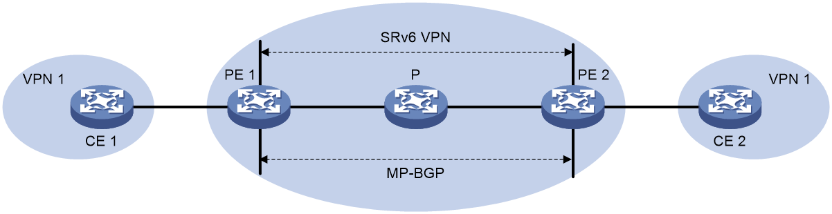
EVPN VPWS over SRv6
EVPN VPWS over SRv6 uses SRv6 tunnels to carry EVPN VPWS services. This technology establishes point-to-point connections between customer sites over the IPv6 backbone network and transparently forwards Layer 2 customer traffic over the IPv6 backbone network.
As shown in Figure 57, PEs set up an SRv6 tunnel by advertising SRv6 SIDs to each other through BGP EVPN routes. On a PE, this SRv6 tunnel is used as a PW to encapsulate and forward Layer 2 data packets received from the local site and destined for a remote site.
Figure 61 EVPN VPWS over SRv6 network diagram

EVPN VPLS over SRv6
EVPN VPLS over SRv6 uses an SRv6 tunnel to carry EVPN VPLS services. This technology establishes point-to-multipoint connections for customer sites over the IPv6 backbone network and transparently forwards Layer 2 customer traffic over the IPv6 backbone network.
As shown in Figure 58, PEs set up an SRv6 tunnel by advertising SRv6 SIDs to each other through BGP EVPN routes. On a PE, this SRv6 tunnel is used as a PW to encapsulate and forward Layer 2 data packets received from the local site and destined for a remote site.
Figure 62 EVPN VPLS over SRv6 network diagram
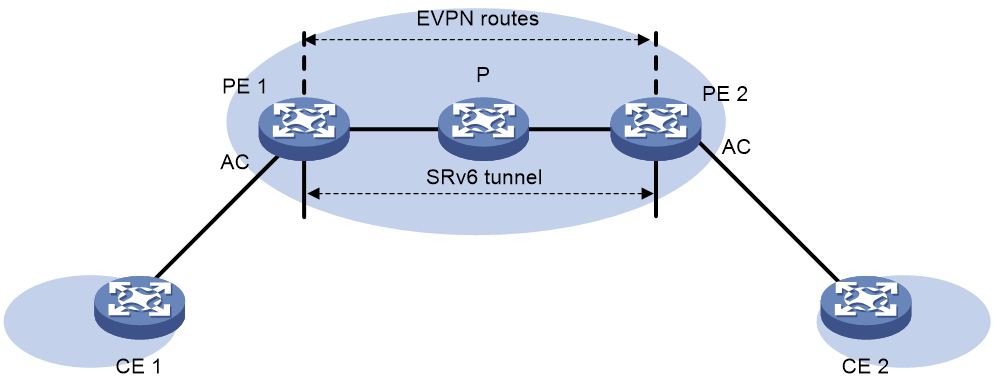
Public network IP over SRv6
As shown in Figure 59, public network IP over SRv6 uses MP-BGP to advertise IPv4 or IPv6 routes of customer sites over the IPv6 backbone network and uses the SRv6 path between the PEs to forward customer traffic.
Public network IP over SRv6 connects geographically dispersed sites that belong to the public network over the IPv6 backbone network.
Figure 63 Public network IP over SRv6 network diagram
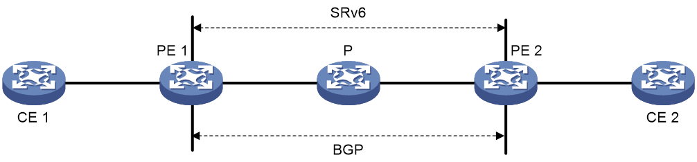
Network slicing
Overview
Network slicing is a method of creating multiple logical networks (network slices) for specific services or users over a common physical network. Each network slice has its own network topology, service level agreement (SLA) demand, and security and HA requirements. With network slices, service providers can fully use the existing network infrastructure and resources to provide differentiated network services for businesses, industries, or users.
Benefits
Network slicing brings the following benefits:
· Differentiated LSA—Carriers or large-scale enterprises provide all their services on the same network, but emerging new services demand different LSAs. For example, auto pilot requires highly on latency and jitter but has no big demand on bandwidth, while VR and high-definition video services have great demand on network bandwidth but no special requirements on latency. A traditional physical network cannot meet differentiated SLA demands, while building independent private networks costs too much. The network slicing solution well solves this issue. It deploys different network slices on the existing physical network for different services as needed.
· Network resource isolation—Some industry customers need secure, reliable, and exclusive network resources. The carrier also wants to provide separated services for different customers so as to prevent general customers from occupying network resources and ensure good user experience for premium customers. The network slicing solution can allocate different resources to different users at the data plane, control plane, and management plane.
· Flexible topology—The development of unified cloud and network technology allows VMs migrate across data centers. Network connection relationship becomes more flexible and complicated. The network slicing solution can use the Flex-Algo technology to meet the requirements of flexible and dynamic changes of network topologies.
Network slicing solution
Network slicing is a solution that uses multiple network technologies to implement logical network creation, resource isolation, differentiated LSA, and flexible topology on a physical network. The network slicing technologies include (but not limited to) the technologies listed in Table 11.
Table 11 Network slicing technology
|
Technology name |
Implementation layer |
Description |
|
IPS |
Management plane Control plane Data plane |
A physical device is virtualized into multiple logical devices called multitenant device contexts (MDCs). Each MDC is assigned separate hardware and software resources, and operates independently. For users, a MDC is an independent physical device. MDCs are highly secure, as they are isolated from each other and cannot communicate with each other directly. |
|
Flex-Algo |
Control plane |
The Flexible Algorithm (Flex-Algo) is a flexible, IGP-based algorithm that allows users to define the metric type for the IGP path calculation, such as cost, link latency, or TE metric, and uses the SPF algorithm to calculate the shortest path to reach the destination address. When calculating the shortest path, Flex-Algo also supports using the link affinity attributes and Shared Risk Link Group (SRLG) as constraints to specify the ultimate topology to include or exclude specific links. Therefore, network elements that participate in different Flex-Algo calculations can form different logical topologies. By deploying multiple Flex-Algo algorithms on a physical network, the network can be divided into multiple separated network slices. |
|
FlexE |
Data plane |
The Flex Ethernet (FlexE) technology decouples Ethernet MAC rate and PHY rate of a high-speed Ethernet interface to implement flexible control of the interface rate. FlexE uses one or multiple IEEE 802.3 high-speed physical interfaces to gain a high total bandwidth, and then flexibly assigns bandwidth to each FlexE logical interface according to the bandwidth requirement of the service on the local interface. The FlexE logical interfaces then can forward data for network slices. |
|
Subinterface channelization |
Data plane |
Subinterface channelization (or subinterface slicing), is a granular network slicing technique that slices a high-speed interface into low-bandwidth subinterfaces called channelized (or sliced) subinterfaces. Each channelized subinterface is assigned a portion of bandwidth for exclusive use. The channelized subinterfaces use their exclusive bandwidths and scheduling queues to forward data, implementing independent data forwarding. |
|
Slice ID |
Data plane |
Slice ID-based network slicing is a technique used in SRv6 networks. It uses a slice ID to uniquely identify a network slice. A service packet forwarded on a sliced network carries a slice ID. The device that receives the packet first searches the FIB for the outgoing interface, and then forwards the packet through the network slice channel that matches the packet's slice ID on the output interface. |
The slice ID based network slicing solution is recommended as it supports a large number (thousand-level) of slices, features simple configuration, and requires less SRv6 SIDs for a forwarding interface (all network slices only need a set of SRv6 locator resources). The following uses the slice ID based network slicing solution as an example to describe the fundamentals of network slicing.
Fundamentals
Slice ID is the key identifier in SRv6 network slicing.
· In this solution, the administrator creates a network slice instance (NSI, a virtual device) with a globally unique slice ID (NSI ID).
· On an interface, the administrator creates a network slice channel for data forwarding of a network slice, and specifies the NSI ID and the bandwidth to be exclusively used by the channel.
· The NSI (virtual device) and the network slice channel that have the same NSI ID are associated to form a network slice.
Packets transmitted in network slices always carry an NSI ID. To forward network slice packets, an SRv6 TE policy must be associated with an NSI ID. An SRv6 TE policy can be associated with an NSI ID as follows:
· The administrator manually specifies an NSI ID for the SRv6 TE policy.
· The device learns the NSI ID from the BGP IPv6 SR policy route advertised by the peer.
The following describes how SRv6 network slice packets are forwarded in an L3VPNv4 over SRv6 TE network.
The SRv6 network contains two network slice instances NSI 1 and NSI 2. The interfaces on PE 1, P, and PE 2 contain network slice channel 1 and network slice channel 2 that correspond to NSI 1 and NSI 2, respectively. In VPN 1, an SRv6 TE policy carries traffic between CE 1 and CE 2, and is associated with NSI 1. A packet from CE 1 to CE 2 is forwarded as follows:
1. CE 1 sends an IPv4 unicast packet to PE 1. After receiving the packet from CE 1, PE 1 looks up the VPN instance routing table, and finds the route that uses an SRv6 TE policy as the output interface. PE 1 encapsulates the following information into the packet:
¡ The SRH header that carries the SID list of the SRv6 TE policy.
¡ The HBH extension header that carries the NSI ID associated with the SRv6 TE policy. The NSI ID is 1.
¡ IPv6 basic header.
2. PE 1 forwards the packet to P through the network slice channel that matches the NSI ID.
3. P forwards the packet based on the SRH header through the network slice channel that matches the NSI ID.
4. After receiving the packet, PE 2 looks up the local SID list based on the destination IPv6 address of the packet, and finds the End SID. PE 2 reduces the SL of the packet by 1, and updates the destination IPv6 address to the End.DT4 SID. PE 2 looks up the local SID list, and performs the forwarding action corresponding to the End.DT4 SID. PE 2 decapsulates the IPv6 header, and finds VPN 1 that matches the End.DT4 SID. It then looks up the routing table of VPN 1, and forwards the packet to CE 2.
Figure 64 SRv6 network slice packet forwarding

iFIT
About iFIT
In-situ Flow Information Telemetry (iFIT) determines network performance by measuring the packet loss and packet delay of service packets transmitted on an MPLS, SR-MPLS, SRv6, G-SRv6, or G-BIER network. iFIT is easy to deploy and can assess network performance accurately.
|
|
NOTE: Support for iFIT on G-SRv6 and G-BIER networks varies by device model. |
Benefits
iFIT has the following advantages over traditional packet loss measurement technologies:
· Accurate measurement of network quality—iFIT directly measures the packet loss and packet delay of real service packets, and thus the measurement result reflects the real network condition.
· Easy deployment—Midstream devices and downstream devices can use iFIT packets to generate measurement information.
· Fast fault locating—iFIT provides flow-based measurement capabilities to achieve real-time monitoring of packet delay and packet loss on a per flow basis.
· Performance data visualization—iFIT displays performance data with a visualized UI and therefore allows fast fault detection.
· Path auto-discovery—Once the ingress point adds iFIT headers to the packets of a user service, the downstream device can identify these packets by their iFIT headers and generate measurement information. The analyzer uses this information to learn the real forwarding path of these packets.
· High extensibility—iFIT is hardware-based and has a small impact on the network.
Application scenarios
iFIT supports both end-to-end measurement and hop-by-hop measurement. These measurement methods are applicable to different networks.
End-to-end measurement
To measure the packet loss and packet delay on the entire network, use end-to-end measurement. As shown in Figure 61, iFIT measures whether packet loss or packet delay occurs between the ingress point (where the target flow enters the IP network) and the egress point (where the flow leaves the network).
Figure 65 End-to-end measurement
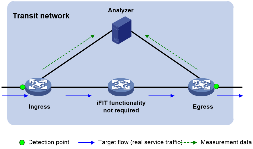
Hop-by-hop measurement
To accurately measure the packet loss and packet delay of each network node, use hop-by-hop measurement. To locate a faulty node, you can divide an end-to-end network into smaller measurement spans. As shown in Figure 62, iFIT measures whether the packet loss and packet delay occurs between the ingress point and egress point, ingress point and transmit point, transmit point and egress point.
Figure 66 Hop-by-hop measurement
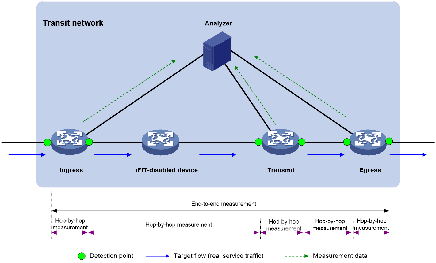
iFIT architecture
Figure 61 and Figure 62 show the important iFIT concepts including target flow, transit network, and measurement system.
Target flow
iFIT provides statistics on a per-flow basis. The target flows can be divided into the following types:
· Static flow—A static flow is a set of flow match criteria configured on the ingress point. The ingress point generates a static flow after you execute the flow command to configure static flow settings and enable iFIT measurement. You can specify a static flow on the ingress point by using any combination of the following items: source IP address/subnet, source port number, destination IP address/subnet, destination port number, protocol type, DSCP value, VPN instance, and next hop.
An iFIT header contains fields to carry information about device ID, flow ID, measurement period, measurement mode, status of packet delay measurement, and status of packet loss measurement.
¡ A device ID uniquely identifies a device in an iFIT measurement network.
¡ A flow ID is automatically generated on the ingress point and passed to the transmit points and egress point. A flow ID and a device ID uniquely identify a flow together.
¡ Within a measurement period, the device starts iFIT measurement, collects and reports the measurement data.
¡ Available measurement modes include end-to-end measurement and hop-by-hop measurement.
· Dynamic flow—A dynamic flow is a service flow dynamically learnt by the device. Dynamic flows are generated as follows:
¡ If the ingress point receives a packet that matches static flow settings, it generates a dynamic flow with the same flow ID as the static flow.
¡ For a transmit point and the egress point, they generate dynamic flows after parsing the iFIT headers of received packets.
The device uses the device ID and the flow ID of an iFIT header to identify a dynamic flow. If the device does not receive another packet that uses the same device ID and flow ID combination for a period of time, the device will delete the dynamic flow.
|
|
NOTE: Support for the Device ID field varies by device model. · For devices that support the Device ID field, they identify an iFIT flow by its device ID and flow ID. · For devices that do not support the Device ID field, they identify an iFIT flow by its flow ID. |
Detection point
A detection point is an interface where iFIT measurement is performed. You can specify detection points as required.
Transit network
The transit network only bears target flows. The target flows are not generated or terminated on the transit network. The transit network can only be a Layer 3 network. Each node on the transit network must be reachable.
Measurement system
The measurement system includes the following device roles:
· Ingress point—The ingress point refers to the point that the flow enters the transit network. It recognizes the target flow, adds iFIT headers to the packets of the flow, collects packet statistics and reports packet statistics to the analyzer.
· Transmit point—A transmit point identifies the target flow by the iFIT header and reports the measurement statistics to the analyzer according to the measurement mode in the iFIT header.
· Egress point—The egress point identifies the target flow by the iFIT header, reports the measurement statistics to the analyzer, and removes the iFIT header from the packet.
· Analyzer—The analyzer collects the statistics reported by the ingress point, transmit points, and egress point for data summarization and calculation.
Operating mechanism
Time synchronization mechanism
Before starting the iFIT measurement, make sure all devices are time synchronized. Therefore, all iFIT-enabled devices can use the same measurement period to report packet statistics to the analyzer. As a best practice, the analyzer and all iFIT-enabled devices are time synchronized to facilitate management and maintenance. iFIT uses Precision Time Protocol (PTP) for time synchronization. For more information about PTP, see PTP configuration in Network Management and Monitoring Configuration Guide.
Packet loss measurement mechanism
The number of incoming packets and that of outgoing packets in a network should be equal within a measurement period. If they are not equal, packet loss occurs in the transit network.
Packet delay measurement mechanism
When a packet passes through multiple detection points, each point will record the timestamp when the packet passes through the point and will report the recorded timestamp to the analyzer. Then the analyzer can use the timestamp values reported by different detection points to calculate the packet delay.
Measurement data reporting mechanism
iFIT-enabled devices push the measurement data to the analyzer by using the gRPC protocol.
Currently, only gRPC dial-out mode is supported. In this mode, iFIT-enabled devices act as gRPC clients and the analyzer acts as a gRPC server (also called a gRPC collector in the gRPC protocol).
An iFIT-enabled device can send iFIT data to the analyzer at either of the following intervals:
· gRPC subscription interval—You can set a gRPC subscription interval when configuring gRPC subscription. The device sends iFIT data to the analyzer at gRPC subscription intervals after connecting to the analyzer, regardless of whether the sampling path is a periodic or event-trigger sampling path.
· iFIT measurement interval—If you do not set a gRPC subscription interval when configuring gRPC subscription, the device performs one of the following tasks:
¡ If the sampling path is a periodic sampling path, the device does not send iFIT data to the analyzer.
¡ If the sampling path is an event-trigger sampling path, the device sends iFIT data to the analyzer at iFIT measurement intervals after connecting to the analyzer.
|
|
NOTE: · The iFIT periodic sampling path is ifit/flowstatistics/flowstatistic. · The iFIT event-trigger sampling paths are insuitoam/measurereport (containing iFIT measurement results) and insuitoam/flowinfo (containing iFIT flow information). |
For more information about gRPC, see gRPC configuration in Telemetry Configuration Guide. For more information about iFIT sampling paths, see the NETCONF API documentation of iFIT.
Working mechanism
The following illustrates the working mechanism of hop-by-hop measurement. Transmit points are not required by end-to-end measurement but end-to-end measurement works similarly as hop-by-hop measurement.
As shown in Figure 63, the flow passes through four devices. Three devices are enabled with iFIT. The iFIT measurement works as follows:
1. The analyzer performs time synchronization with all iFIT-enabled devices through the PTP protocol.
2. The iFIT-enabled devices takes the following actions:
a. The ingress point parses the packets to identify the target flow. It encapsulates iFIT headers to the packets, counts the number of packets, and reports the packet quantity and timestamp to the analyzer through gRPC periodically.
The ingress point is the interface bound to the target flow.
b. A transmit point counts the number of packets containing iFIT headers and reports the packet quantity and timestamp to the analyzer through gRPC periodically.
When the target flow passes through an iFIT-enabled device, the incoming and outgoing interfaces for the target flow are transmit points.
c. The egress point parses the packets to identify the target flow. It counts the number of packets containing iFIT headers, reports the packet quantity and timestamp to the analyzer through gRPC periodically, removes iFIT headers from the packets and forwards the packets.
When the target flow leaves the transit network from an iFIT-enabled device, the incoming or outgoing interface on the iFIT-enabled device is the egress point. The interface used as the egress point varies by device model.
3. The analyzer calculates the packet delay for the target flow of the same period and same instance.
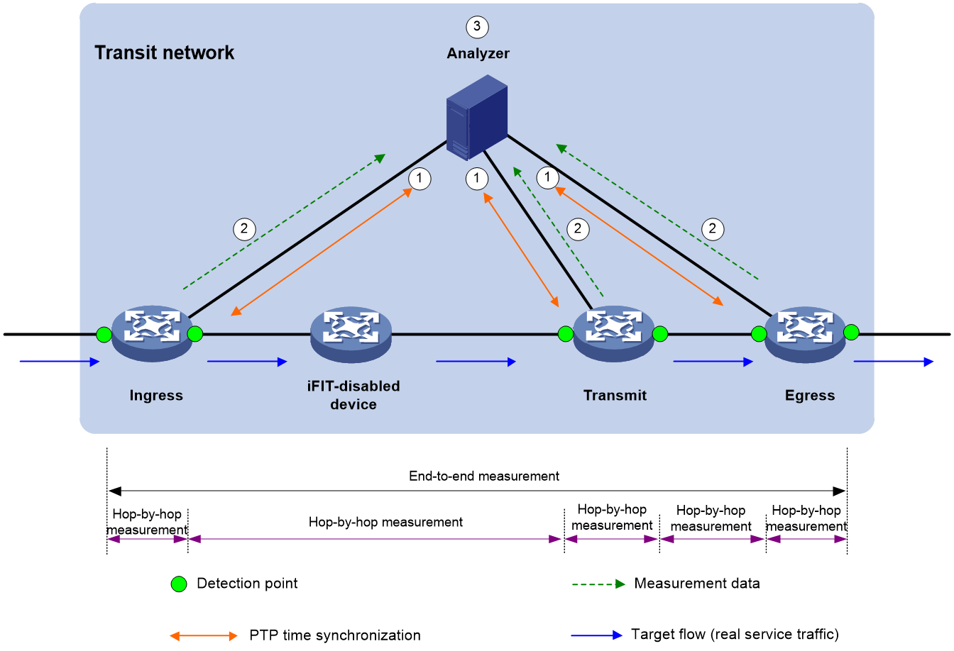
BIER
Overview
Background
In traditional multicast and multicast VPN, the device needs to establish a multicast distribution tree for each multicast flow. Each node on the multicast distribution tree needs to be aware of multicast services and maintain multicast flow state. For example, on a public network configured with PIM, a multicast distribution tree needs to be established for each multicast flow. In NG MVPN, the device needs to establish a P2MP tunnel for each multicast flow, which is an equivalent of a P2MP multicast distribution tree. As the multicast services grow, multicast distribution trees increase significantly, and a multicast node needs to maintain states of a large number of multicast flows. When the network topology changes, multicast entries converge slowly.
In addition, the coexistence of unicast routing protocols, multicast routing protocols, and MPLS on the network adds the complexity of the control plane of the network. This makes the network converge slowly, difficult to maintain, and difficult to evolve to the SDN architecture.
Bit Index Explicit Replication (BIER) is a new architecture for the forwarding of multicast data packets. BIER encapsulates the destination nodes of multicast packets in a bit string. It does not require a protocol for explicitly building multicast distribution trees, nor does it require intermediate nodes to maintain any per-flow state.
In a BIER network, multicast packets are forwarded according to the Bit Index Forwarding Table (BIFT) on the Bit-Forwarding Router (BFR).
H3C supports two encapsulation types: Generalized BIER (G-BIER) and Bit Index Explicit Replication IPv6 Encapsulation (BIERv6).
Benefits
BIER has the following benefits:
· Good multicast service scalability
The BIFT established on a BFR is a common forwarding table independent of multicast services. Intermediate nodes do not need to maintain any per-flow state. Both public multicast packets and private multicast packets can be forwarded according to the BIFT.
· Simplified service deployment and maintenance
Intermediate nodes are not aware of multicast services. Deployment of multicast services does not involve intermediate nodes. Changes to multicast services do not affect intermediate nodes.
· Simplified control plane
Intermediate nodes in the network do not need to run PIM. The control plane protocols are IGP and BGP.
· Easy evolution to SDN
Deployment of multicast services does not involve intermediate nodes. BIER encapsulation is added to packets on the ingress node to guide the replication of multicast packets. The BIER encapsulation carries a bit string identifying the output interface for multicast packets. Intermediate nodes replicates and forwards multicast packets according to the bit string.
BIER network structure
A router that supports BIER is known as a Bit-Forwarding Router (BFR). As shown in Figure 64, a BIER network consists of the following BFRs:
· Bit Forwarding Ingress Router (BFIR)—A multicast data packet enters a BIER domain at a BFIR. A BFIR encapsulates the multicast data packet as a BFIR packet.
· Transit BFR—A transit BFR receives a multicast data packet from one BFR to another BFR in the same BIER domain.
· Bit Forwarding Egress Router (BFER)—A multicast data packet leaves a BIER domain at a BFER. A BFER decapsulates the multicast data packet and sends it to multicast receivers.
Figure 68 BIER network structure
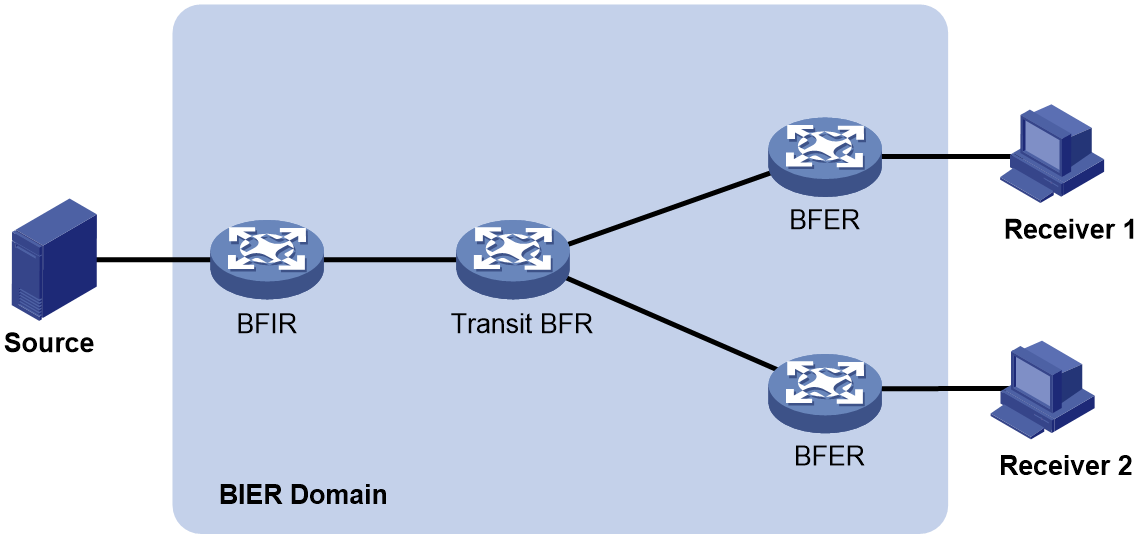
Basic concepts
BIER domain and BIER sub-domain
All BFRs in a routing domain or a management domain are referred to as a BIER domain. A BIER domain can contain one or more sub-domains. Each sub-domain is identified by a sub-domain ID. All BFIRs and BFERs in a sub-domain are called BIER edge devices.
BFR ID
A BFR ID uniquely identifies a BIER edge device in a sub-domain. A transit BFR does not need to have a BFR ID.
BFR prefix
A BFR prefix is an IP address that uniquely identifies a BFR in a sub-domain. A BFR prefix must be routable in the sub-domain and can only be the IP address of a loopback interface.
Bit string
A bit string represents a set of BIER edge devices, with each bit corresponding to a BFR ID, starting from the rightmost position. The bit string length (BSL) refers to the number of bits in the bit string. A bit string with three bits can identify a maximum of three BIER edge devices. The BIER edge device with BFR ID 1 is represented as 001.
Set identifier
When the number of BFR IDs is greater than the number of bits in the bit string, the bit string needs to be divided into sets identified by set identifiers (SI). For example, if the maximum BFR ID is 1024 in a BIER sub-domain and the bit string length is 256, the bit string needs to be divided into four SIs (SI 0, SI 1, SI 2, and SI 3).
Bit Index Routing Table
The Bit Index Routing Table (BIRT) is generated based on the BIER information ((sub-domain, BSL, and BFR ID) and routing information carried by IGP or BGP. The BIRT is used to guide the forwarding of BIER packets in a BIER sub-domain.
Forwarding Bit Mask
The Forwarding Bit Mask (F-BM) represents a set of edge nodes in a BIER sub-domain that are reachable through a BFR neighbor (BFR-NBR). The bit mask is obtained by taking the logical OR of the bit strings of all reachable edge nodes.
Bit Index Forwarding Table
The Bit Index Forwarding Table (BIFT) can guide the per-hop forwarding of multicast traffic in a BIER sub-domain.
The BIFT is used to map from the BFR ID of a BFER to the corresponding F-BM and BFR-NBR. Multiple BIFT can exist on a BFR. Each BIFT is identified by a combination of the BSL, SD, and SI).
Layering
As specified in RFC 8279, the BIER architecture consists of three layers: routing underlay, BIER layer, and multicast flow overlay.
Routing underlay
The routing underlay uses an IGP (only IS-IS is supported) to flood BIER information through extended TLVs in a BIER sub-domain. A BFR generates routes to all BFR prefixes (BFR IDs) based on the IGP. Therefore, the routing underlay establishes adjacencies between pairs of BFRs and determines one or more best paths from a given BFR to a given set of BFRs.
BIER layer
The BIER layer consists of the protocols and procedures that are used in order to transmit a multicast data packet across a BIER domain.
1. A BFR advertises the BIER information to other BFRs in the BIER domain through IGP.
2. Other BFRs generate a BIRT and a BIFT according to the advertised information.
3. An intermediate BFR forwards a BIER-encapsulated packet by looking up the BIFT table.
Multicast flow overlay
The multicast flow overlay is responsible for control plane processing. It collects join and leave messages of multicast groups between BFIRs and BFERs.
At the forwarding plane, when a BFIR receives a multicast data packet from outside the BIER domain, the BFIR determines the set of BFERs for that packet. When a BFER receives a BIER-encapsulated packet from inside the BIER domain, the BFER decapsulates the packet and forwards it.
BIER packet format
RFC 8279 defines multiple encapsulation types for BIER. Different encapsulation types have different packet formats. Generalized BIER (G-BIER) and Bit Index Explicit Replication IPv6 Encapsulation (BIERv6) are supported in the current software version.
· G-BIER—Proposed by Chine Mobile, H3C, Huawei, and ZTE. G-BIER revised the RFC-defined BIER header to adapt to IPv6.
· BIERv6—Based on native IPv6. BIERv6 combines the advantages of IPv6 and BIER and can integrate with SRv6 seamlessly. To use BIERv6, all BFRs in a sub-domain must support SRv6.
G-BIER packet format
G-BIER encapsulates a multicast data packet as a G-BIER packet by adding a new IPv6 header and a BIER header. As shown in Figure 65, the Next Header field in the IPv6 header is 60, which indicates that the next header is Destination Options Header (DOH).
G-BIER uses the following conventions related to the following fields in the new IPv6 header:
· Source Address—The source address is the multicast service source address and remains unchanged when a multicast packet is transmitted over a public network. The source address is composed of the prefix of a BFIR and the multicast service ID. The prefix of a BFIR identifies the network location of the BFIR, and the multicast service ID identifies the MVPN instance.
· Destination Address—The destination address is the multicast policy reserved address (MPRA) for BIER forwarding. This address must be routable in a sub-domain. When a BFR receives an IPv6 address with the locally configured MPRA as the destination address, it performs G-BIER forwarding for the packet.
The BIER header contains the following fields:
· Next Header—An 8-bit field to identify the type of the next header.
· Hdr Ext Len—An 8-bit field to indicate the length of the IPv6 extension header.
· Option Type (TO)—An 8-bit field, which is fixed at G-BIER.
· Option Length—An 8-bit field to indicate the option length.
· BSL—A 4-bit field to identify the length in bits of the BitString. The value range is 1 to 7.
¡ 1 indicates that the bit length is 64 bits.
¡ 2 indicates that the bit length is 128 bits.
¡ 3 indicates that the bit length is 256 bits.
¡ 4 indicates that the bit length is 512 bits.
¡ 5 indicates that the bit length is 1024 bits.
¡ 6 indicates that the bit length is 2048 bits.
¡ 7 indicates that the bit length is 4096 bits.
· SD—An 8-bit field to indicate the ID of the BIER sub-domain.
· SI—An 8-bit field to indicate the set identifier.
· Rsv—A 4-bit, reserved field.
· TTL—An 8-bit Time to Live field to prevent loops.
· Version—A 4-bit field to identify the version of the BIER header, which is fixed at 0.
· Entropy—A 20-bit field to specify an entropy value used for load-balancing purposes when there are ECMP paths. The load-balancing procedure will choose the same path for any two packets that have the same entropy value and the same BitString.
· OAM—A 4-bit field that can be used for OAM purposes. The device value of this field is 0.
· DSCP—A 7-bit field to indicate the forwarding priority of the packet.
· Bit String—This field holds the BitString that, together with the packet's SI and SD, identifies the destination BFERs for the packet.
Figure 69 G-BIER packet format
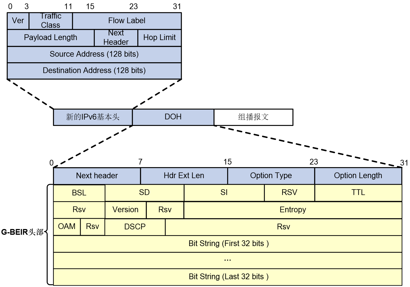
BIERv6 packet format
G-BIER encapsulates a multicast data packet as a G-BIER packet by adding a new IPv6 header and a BIERv6 header. As shown in Figure 66, the Next Header field in the IPv6 header is 60, which indicates that the next header is Destination Options Header (DOH).
G-BIER uses the following conventions related to the following fields in the new IPv6 header:
· Source Address—The source address is the BIERv6 tunnel source address and remains unchanged when a multicast packet is transmitted over a public network. For more information about BIERv6 tunnel source address, see multicast VPN configuration in IP Multicast Configuration Guide.
· Destination Address—The destination address is the End.BIER SID for BIER forwarding. This address must be routable in a sub-domain. The End.BIER SID is configured by using the end-bier locator command.
The BIER header contains the following fields:
· Next Header—An 8-bit field to identify the type of the next header.
· Hdr Ext Len—An 8-bit field to indicate the length of the IPv6 extension header.
· Option Type (TO)—An 8-bit field, which is fixed at G-BIER.
· Option Length—An 8-bit field to indicate the option length.
· BIFT-ID—A 20-bit field to indicate the ID of a BIFT.
· TC—A 3-bit field to indicate the traffic class for QoS.
· S—A 1-bit reserved field.
· TTL—An 8-bit Time to Live field to prevent loops. When a packets traverses a BIERv6 node, its TTL decreases by 1. When the TTL is 0, the packet is dropped.
· Nibble—A 4-bit reserved field and is fixed at 0.
· Version—A 4-bit field to identify the version of the BIERv6 header, which is fixed at 0.
· BSL—A 4-bit field to identify the length in bits of the BitString. The value range is 1 to 7.
¡ 1 indicates that the bit length is 64 bits.
¡ 2 indicates that the bit length is 128 bits.
¡ 3 indicates that the bit length is 256 bits.
¡ 4 indicates that the bit length is 512 bits.
¡ 5 indicates that the bit length is 1024 bits.
¡ 6 indicates that the bit length is 2048 bits.
¡ 7 indicates that the bit length is 4096 bits.
· Entropy—A 20-bit field to specify an entropy value used for load-balancing purposes when there are ECMP paths. The load-balancing procedure will choose the same path for any two packets that have the same entropy value and the same BitString.
· OAM—A 2-bit field that can be used for OAM purposes. The device value of this field is 0.
· Rsv—A 2-bit, reserved field.
· DSCP—A 6-bit field to indicate the forwarding priority of the packet.
· Proto—A 6-bit field to indicate the payload type after the BIERv6 header.
· BFIR ID—A 16-bit field to indicate the BFR ID of the BFIR.
Figure 70 G-BIER packet format
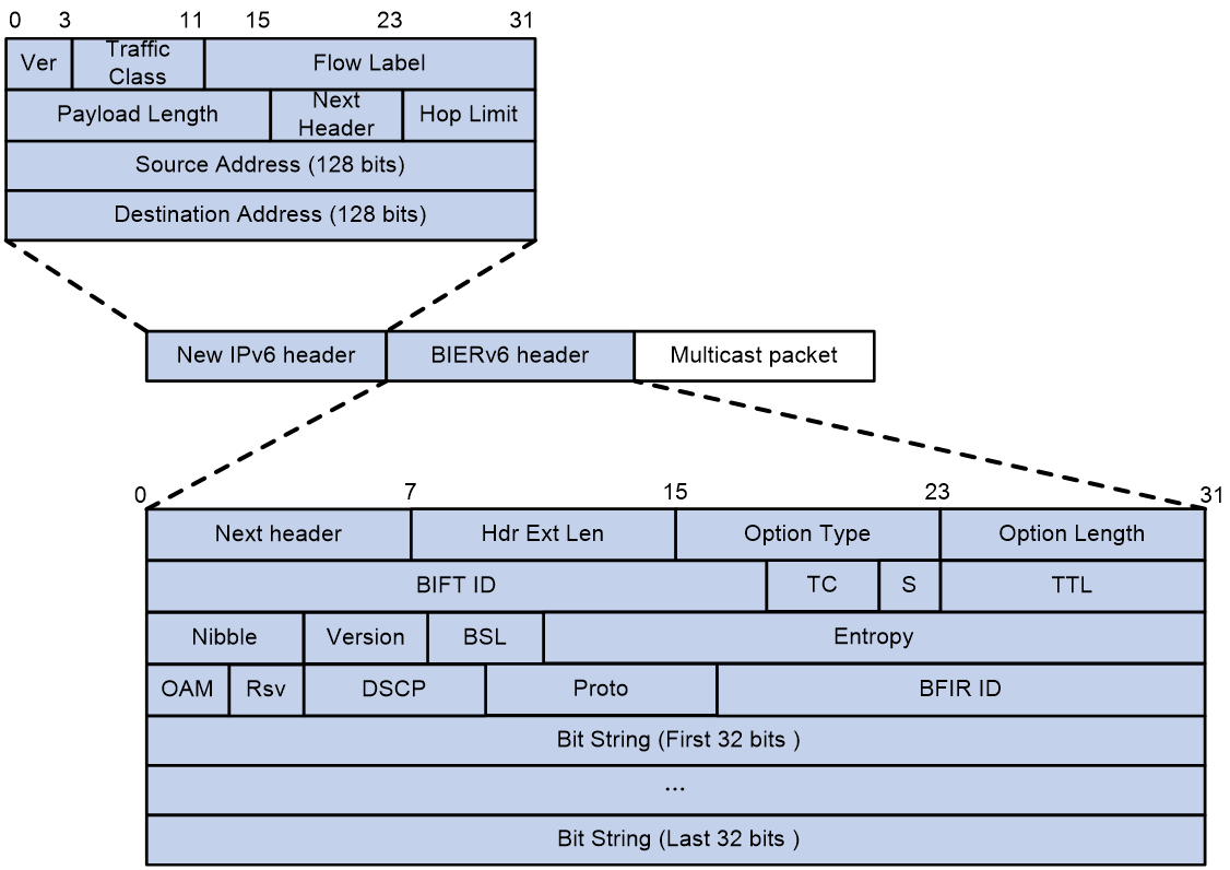
BIER control plane
The BIER information ((sub-domain, BSL, and BFR ID) on a BFR is flooded in a BIER domain through IGP. IGP uses the flooded BIER information to calculate the shortest path tree with the BFIR as the root and the transit BFRs and BFERs as leafs. The BFR generates a BIRT according to the shortest path tree and then generates a BIFT to guide BIER forwarding.
As shown in Figure 67, a BIER domain contains BIER-capable nodes and BIER-incapable nodes (device G). All subnodes of a BIER-incapable node will be added to the shortest path tree as leaf nodes. If the subnodes are also BIER incapable, subnodes that support BIER will continue to be found. For example, Device G does not support BIER, and it will transfer the BIER information of Device C and Device E to Device B. Device B generates BIFT entries with Device C and Device E as the next hops.
Figure 71 BIER control plane BIFT
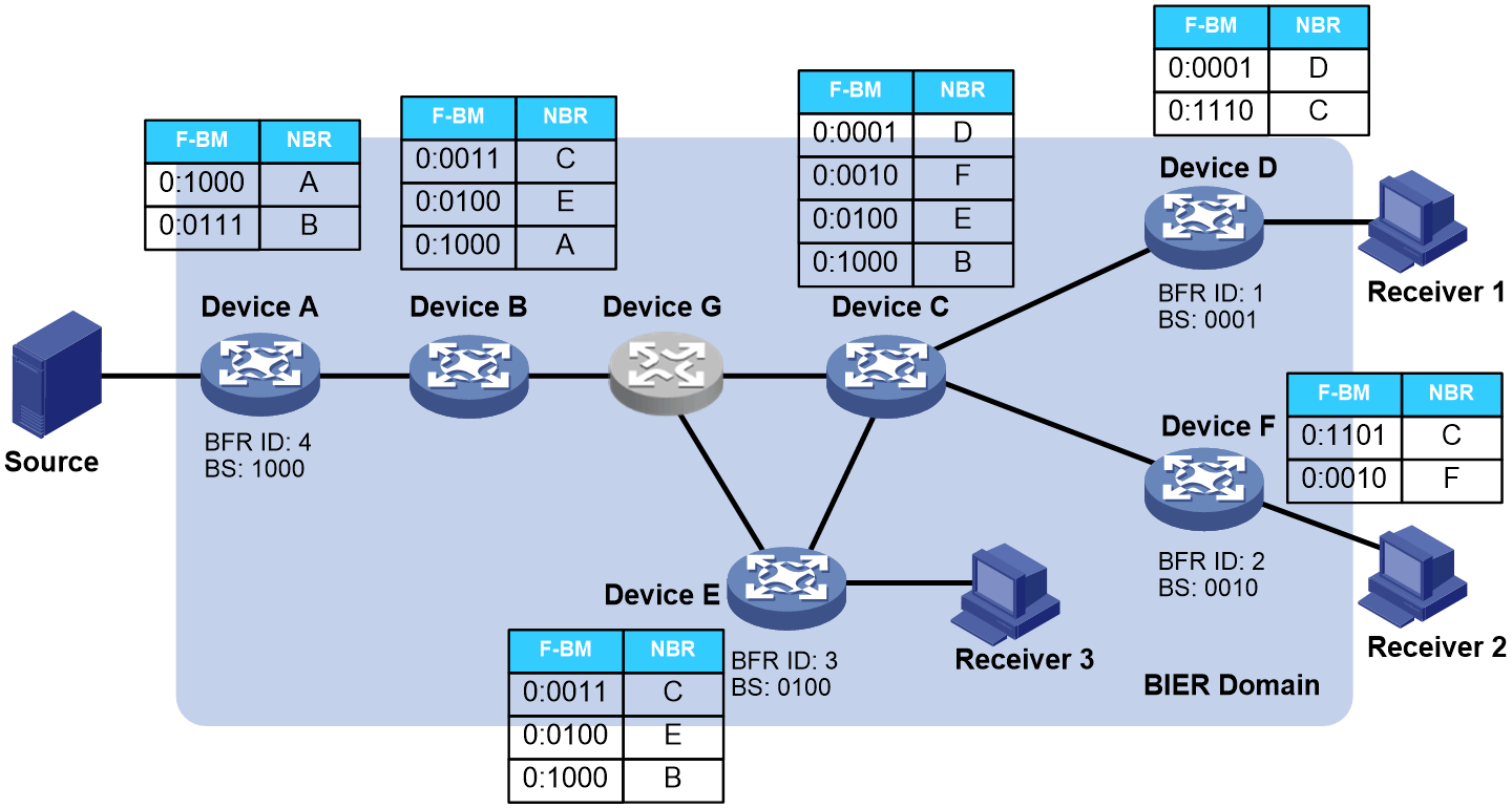
BIER forwarding process
When receiving a multicast packet, a BFIR looks up the multicast forwarding table to obtain the BIFT ID and bit string of the multicast forwarding entry. The bit string represents all reachable BFERs. The BFIR matches a BIFT according to the BIFT ID and forwards the multicast packet according to the bit string and the BIFT entry. When receiving the multicast packet, a BFER forwards it according to the multicast forwarding table.
When a multicast packet needs to pass through a BIER-incapable node, you can use some methods to traverse the BIER-incapable node. The method used depends on the outer encapsulation of BIER. For MPLS encapsulation, you can use LSP to traverse a BIER-incapable node. For IPv6 encapsulation, you can use IPv6 unicast routes to traverse a BIER-incapable node.
As shown in Figure 68, each device in the sub-domain calculated a BIFT entry to another device through IGP. The hosts connected to Device D and Device E are multicast receivers. Device A learned the BFR IDs and BFR prefixes of Device D and Device E through MVPN routes. Device A is in the same sub-domain as Device D and Device E. When Device A receives a multicast packet, the BIER forwarding process is as follows:
1. Device A looks up the multicast forwarding table to obtain the BIFT ID and bit string of the multicast forwarding entry. Device A finds the BIFT according to the BIFT ID, performs a logical AND operation on the bit string and each F-BM in the BIFT. Then, it replicates and encapsulates the multicast packet, and forwards the multicast packet to Device B.
2. When receiving the multicast packet, Device B performs the same logical AND operation on the bit string and each F-BM in the BIFT as in step 1. The next hops are Device C and Device E after a BIER-incapable node (Device G). Device B uses a method to traverse Device G, replicates the multicast packet, encapsulates it in BIER, and sends it to Device C and Device E.
3. When receiving the multicast packet, Device C performs the same logical AND operation on the bit string and each F-BM in the BIFT as in step 1. Then, Device C replicates the multicast packet, encapsulates it in BIER, and sends it to Device D and Device F.
4. After receiving the BIER packet, each of the three devices (Device D, Device E, or Device F) determines that the result of the logical AND operation on its F-BM and the BS value in the packet is not 0. each of them decapsulates the BIER packet and sends the multicast packet to downstream receivers according to the multicast routing table.
Figure 72 BIER forwarding process