- Released At: 18-12-2024
- Page Views:
- Downloads:
- Table of Contents
- Related Documents
-
SRv6 High Availability Technology White Paper
Copyright © 2024 New H3C Technologies Co., Ltd. All rights reserved.
No part of this manual may be reproduced or transmitted in any form or by any means without prior written consent of New H3C Technologies Co., Ltd.
Except for the trademarks of New H3C Technologies Co., Ltd., any trademarks that may be mentioned in this document are the property of their respective owners.
The content in this article is general technical information. Some information may not be applicable to the product you purchased.
Contents
SRv6 high availability mechanism
Microloop avoidance upon network failure
Microloop avoidance upon failure recovery
SRv6 intermediate node protection
Scenario of TI-LFA FRR Failure
Intermediate node protection in SRv6
Difference between intermediate node protection and TI-LFA FRR
Application scenario of endpoint protection in SRv6
Overview
Technical background
In the SRv6 network, when a link or node device disrupts or recovers from a disruption, packet loss might occur. To ensure the steady forwarding of service traffic in the SRv6 network, SRv6 offers high availability measures. These measures prevent long-term interruption of service traffic and enhance network quality.
SRv6 provides the following high availability protection mechanisms:
· Topology-Independent Loop-Free Alternate Fast Reroute (TI-LFA FRR)—Automatically calculates backup protection paths under any topology.
· SRv6 microloop prevention mechanism—It avoids the short-term loop issues in the network caused by the differences in the convergence order of IGP protocol among different nodes.
· Protection of intermediate nodes in SRv6—This has been implemented for protecting essential nodes from faults in the forwarding scenario of SRv6 TE Policy.
· SRv6 end node protection—Achieves protection against SRv6 TE policy end node faults in the IP L3VPN/EVPN L3VPN/EVPN VPLS/EVPN VPWS over SRv6 TE policy network. It is only applicable to dual homing network scenarios.
Advantages
The SRv6 high availability mechanism has the following characteristics:
· High protection rate
Based on SRv6, combined with the RLFA FRR algorithm, a highly efficient TI-LFA FRR algorithm is formed, improving the protection rate.
· Extensive deployment
SRv6 high availability supports any topology and can compensate for the shortcomings of traditional tunnel protection technology.
SRv6 high availability mechanism
TI-LFA FRR
About FRR
Emergence and development of FRR technology
Some services are highly sensitive to packet loss in the network. When a link or node device in the network experiences a fault, these types of services require traffic forwarding disruption to not exceed tens of milliseconds. However, the route recalculation and convergence time in the network topology usually cannot meet the above requirements. Enabling the fast reroute (FRR) feature on neighboring devices of the protected links or nodes can minimize traffic package loss during the route reconvergence process to the greatest extent. The device node that has activated the FRR function is known as the point of local repair. The PLR node calculates the shortest path to the destination network, and simultaneously computes a backup path. Both the main and backup paths are then added to the FIB forwarding table. When a protected link or node encounters a fault, traffic can be immediately forwarded via the backup path of the PLR node, eliminating the wait for route reconvergence, thus minimizing traffic package loss to the utmost.
In the order of their appearance time, there are several types of FRR algorithm mechanisms as follows:
· Loop-Free Alternate Fast Reroute (LFA FRR) is a technique that provides fast rerouting without forming loops.
· Remote Loop-Free Alternate Fast Reroute (RLFA FRR), which refers to a distance-independent, loop-free backup fast reroute.
· The TI-LFA FRR (Topology-Independent Loop-Free Alternate Fast Reroute) is applicable for SRv6 and SR-MPLS networking.
From LFA FRR technology to RLFA FRR technology, and then to TI-LFA FRR technology, each generation of FRR technology inherits the basic algorithm and addresses issues of the previous generation. Both LFA FRR and RLFA FRR have certain limitations. To better understand TI-LFA FRR tech, see the algorithm mechanisms of LFA FRR and RLFA FRR, as well as some of the challenges they are facing.
LFA FRR
Mechanism of LFA FRR algorithm
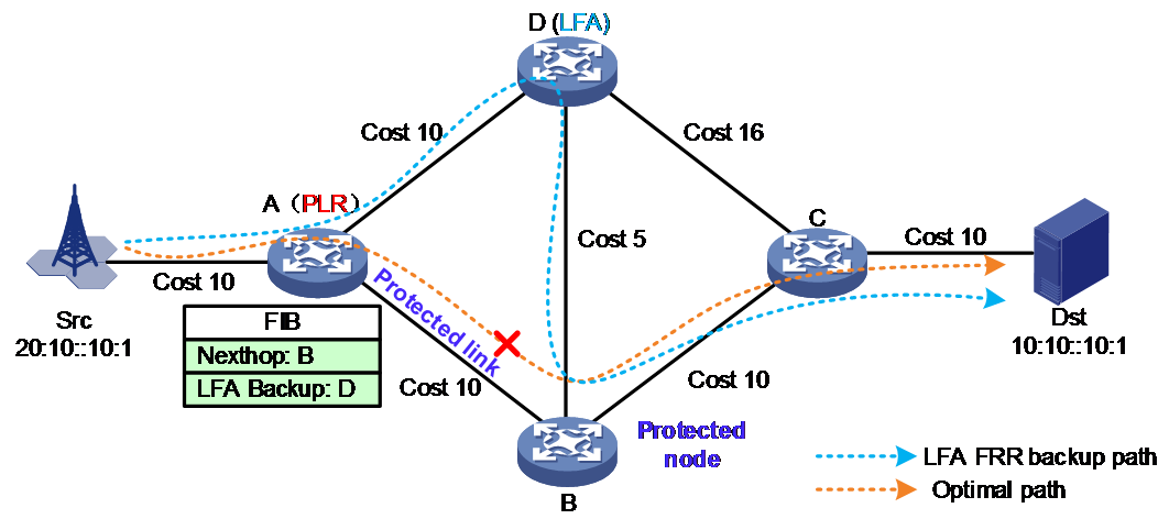
The earliest FRR technology was LFA FRR. As shown in Figure 1, the key to calculating the backup path for LFA FRR is to find a neighbor node of the PLR as the loop-free alternate node (LFA node). This ensures traffic can be forwarded from the PLR to the LFA node and then reach the destination node without passing through the protected link or protected node. Here are the calculation steps:
1. The network administrator determines the optimal path for business traffic from the source to the destination. They then validate the link (A→B) or node (B node) on this path that requires protection. Afterwards, they select the upstream node (A node) directly connected to the protected link or node on the aforementioned optimal path as the point of local repair (PLR). The LFA FRR function is then activated at this point.
2. By default, PLR prioritizes calculating the backup path for node protection.
¡ Use PLR as the root node of the shortest path first (SPF) tree, and find all the neighboring nodes (D) that are accessible without passing through the protected nodes (B). Use these neighbor nodes as root nodes, and run the SPF algorithm to calculate the path to reach the destination Dst.
¡ Check the path from the neighbor node (D) to the destination node Dst, ensuring it meets the following condition to avoid loops: Distance (D, Dst) < Distance (D, B) + Distance (B, Dst), where Distance (X, Y) represents the shortest reach from X to Y. The check revealed that the neighbor node D does not meet the aforementioned condition. Namely, the shortest path cost value from neighbor node D to destination Dst is 25, which equals the sum of the shortest path cost from neighbor node D to the protected node B (5) and the shortest path cost from the protected node B to the destination Dst (20). If the node D is chosen as the protected node, when the traffic reaches D, it may still bypass and go through the protected node B, then be forwarded from B to Dst, which fails to perform the node protection function. Therefore, in the above topology, there is no ring-free backup path that satisfies node protection.
¡ If a neighbor node from the above steps can meet the ring-free verification condition for node protection, then the computed egress interface and next hop will be written into the FIB forwarding table of the PLR. In this case, it is not necessary to carry out calculations for link protection in the next step. Otherwise, PLR continues to calculate the backup path for the next step of link protection.
3. PLR calculates the backup path for link protection:
¡ Use PLR as the root node of the SPF tree, find all neighbor nodes (D) that can be reached without passing through the protected link (A→B), use these neighbor nodes as the root nodes, and run the SPF algorithm to calculate the path to the destination Dst.
¡ To verify the path from the neighbor node (D) to the destination node Dst, the following loop-free condition must be satisfied: Distance (D, Dst) < Distance (D, PLR) + Distance (PLR, Dst), where Distance (X, Y) represents the shortest distance from X to Y. The verification finds that the neighbor node D can meet the above condition, therefore neighbor node D can serve as the backup path LFA for link protection.
¡ If no neighbor nodes in the above steps meet the link protection ring-free verification condition, then LFA FRR cannot calculate the backup protection path for this network topology.
Issues faced by the LFA FRR algorithm
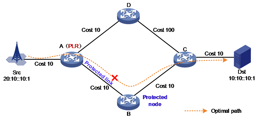
As shown in Figure 2, LFA FRR cannot calculate a backup protection path due to the excessively high cost value of the link from D to C. In reality, the traffic can protect node B by successively bypassing nodes D and C. Therefore, the effectiveness of LFA FRR might be restricted by network topology. In certain scenarios, especially in ring-shaped network topologies, it might not be able to calculate backup protection paths. Therefore, the LFA FRR technology cannot achieve topology independence. Based on the statistics in RFC 6571, the coverage of backup protection scenarios provided by LFA FRR can reach 80% to 90% in topology scenarios.
Figure 2 LFA FRR cannot calculate the backup protection path
RLFA FRR
Mechanism of RLFA FRR algorithm
To increase the scenario coverage of the LFA FRR algorithm, RFC 7490 defined Remote Loop-Free Alternate Fast Reroute (RLFA FRR). The crucial part of the RLFA FRR algorithm is to find a remote node as a non-augmented node, namely the RLFA node. After the traffic is forwarded from the PLR to this RLFA node, it can reach the destination node without going through the protected link or protected node. Compared to the LFA FRR algorithm, the RLFA FRR algorithm provides more protection possibilities, as the protective nodes it finds are not necessarily neighbors of the PLR. Therefore, the scenario coverage of RLFA FRR has increased to 95% to 99%.
For example, taking the topology shown in Figure 3 as an example, for service traffic from the source node Src through the optimal path to the destination node Dst, to protect the link between B and E, you can select node B, which is the upstream direct-connected node of the protected link on the optimal path, as the PLR. You can then initiate the RLFA FRR function on the PLR node.
The RLFA FRR algorithm defines the following concept in order to find an RLFA protection node:
· P space—Construct an SPF tree with PLR as the root node. The set of all nodes reachable from the root node without passing through protected links or protected nodes is called P space. The nodes in the space P shown in Figure 3 include Src, B, and C.
· Extended P space—Using the neighbor nodes (excluding the protected node) of PLR as root nodes, set up the SPF trees respectively. All the nodes that can be reached from the root node without passing through the protected link or protected node are the extended P space. The extended P space includes the P space. The node defined within the extended P space is known as the P node, and the neighboring node of PLR is defined as the N node. The extended P space in Figure 3 below includes nodes Src, B, C, and D. The node P satisfies the following loop-free condition: Distance (N, P) is less than the sum of Distance (N, PLR) and Distance (PLR, P).
· Q space—Establish a reverse SPF tree with the destination node Dst as the root node. The set of nodes that can be reached from the root node without passing through protected links or protected nodes is called Q space (ECMP paths exist from the root node to the node, and the ECMP paths cannot pass through protected links or nodes). Nodes within the Q space are called Q nodes. The nodes in the diagram below include Dst, E, and D in the Q space. Node Q meets the following condition: Distance (Q, Dst) < Distance (Q, PLR) + Distance (PLR, Dst)
· Intersection of PQ—The intersection of P nodes and Q nodes, which can serve as protection nodes for RLFA. If there are multiple intersections of P nodes and Q nodes, typically, the one closer to the PLR node is selected as the RLFA protection node.
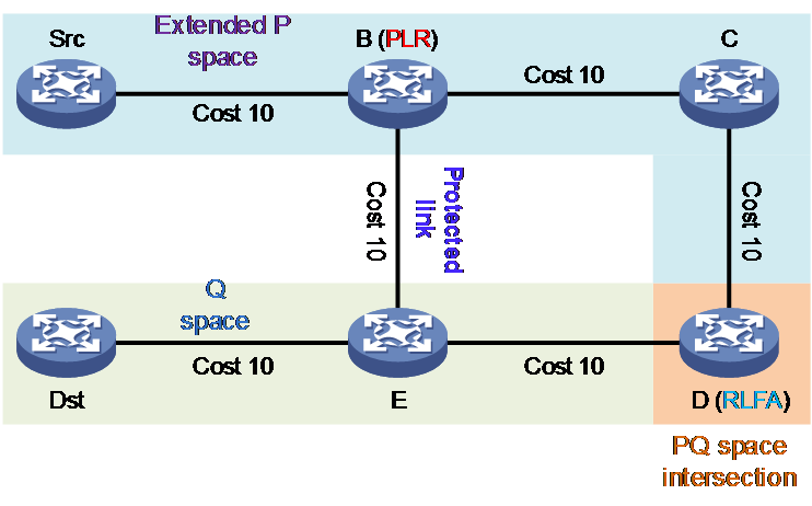
Using the topology shown in Figure 3 as an example, if node B runs the LFA FRR algorithm, its neighbor node C fails to meet the loop-free condition: Distance (C, Dst) < Distance (C, PLR) + Distance (PLR, Dst). Therefore, the LFA FRR algorithm cannot provide FRR backup for the protected link B→E.
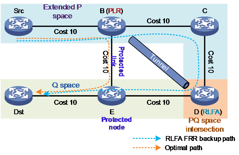
Node B runs the RLFA FRR algorithm, which can calculate the backup path as shown in Figure 4. The steps of the RLFA FRR algorithm are as follows:
1. The network administrator determines the optimal path that business traffic takes from source to destination. Along this path, they confirm the link (B→E) or node (E node) that needs protection, and then they choose the directly connected upstream node (B node) on the path as the PLR, which is connected to the protected link or node.
2. By default, PLR gives priority to RLFA nodes that can provide node protection.
¡ Calculate the extended P space of protection node E, including Src, B, C, and D.
¡ Calculate the Q space of the protected node E, only including Dst.
¡ The expansion spaces P and Q do not share any common nodes. Therefore, the RLFA FRR algorithm cannot find the RLFA protection node and is unable to compute the backup path for node protection. Continue to step 3 to calculate the backup path for link protection. If there is an intersection node between P space and Q space, select the one closer to the PLR node as the RLFA protection node, and proceed directly to step 4.
3. The PLR calculation can achieve link protection for RLFA nodes.
¡ Calculate the extended P space of the protection link, which includes Src, B, C, and D.
¡ Calculate the Q-space of the protection link, including Dst, E, and D.
¡ Choose node D, which is the intersection of the extended P space and Q space, as the RLFA protection node.
Figure 4 RLFA FRR backup protection
Issues faced by the RLFA FRR algorithm
Although RLFA FRR has increased the scenario coverage rate to 95% to 99%, it still cannot achieve 100% backup protection. For example, in the topology depicted in Figure 4, if the link cost between C and D is adjusted to 100, then the PQ space calculated by the RLFA FRR algorithm will have no intersecting nodes. Therefore, if the backup protection path cannot be calculated, the RLFA FRR technical feature cannot achieve topology independence.
TI-LFA FRR
TI-LFA FRR takes advantage of SR's source routing mechanism, allowing the PLR node to specify an explicit path as the backup path for FRR, and strictly restricting this path from passing through protected links or protected nodes.
The TI-LFA FRR has inherited the algorithm for calculating PQ nodes from the RLFA FRR technical method. When there are no intersecting nodes in the PQ space, the TI-LFA FRR algorithm can compute a constraint path to indicate how to reach Q space from P space. This constraint path is referred to as repair list.
Compared to RLFA FRR, the TI-LFA FRR algorithm can solve the problem of calculating FRR backup paths when there are no intersecting nodes in the PQ space. Therefore, the TI-LFA FRR algorithm can achieve 100% scenario coverage, providing topology-independent FRR backup protection.
TI-LFA FRR path calculation
TI-LFA FRR path calculation includes the following scenarios:
· No intersecting node exists between the extended P space and Q space. At this point, the repair list consists of the "End SID of the last P node of the fault-converged SPF tree + all End.X SID on the path from the last P node to the first Q node of this SPF tree" SID list. If the last P node of the fault-converged SPF tree is directly connected to the PLR, the repair list does not need to include the End SID of the last P node, just the End.X SID.
· When the extended spaces P and Q intersect at a node. At this point, there exists at least one node that belongs to both the extended P space and Q space. This indicates that from this node, it is not necessary to pass through the protected link or protected node to reach the destination node, PLR, or the neighbor of the PLR. At this time, the TI-LFA FRR algorithm is the same as the RLFA FRR algorithm. The repair list is either empty or only includes the "End SID of the last P node on the SPF tree after fault convergence". If the last P node of the SPF tree is directly connected to the PLR after fault convergence, then the repair list will be empty. Otherwise, the repair list will contain an End SID. This situation will not be discussed in detail here.
As shown in Figure 5, the extended P space and Q space have no intersection. Src is the source node, Dst is the destination node, and the optimal path for service traffic from the source node to the destination node is Src→A→B→Dst. To protect the B node or the link between A and B, you can select the upstream directly connected node A of the protected node on the optimal path as the PLR and enable the TI-LFA FRR function on the PLR node.
Figure 5 TI-LFA FRR node protection
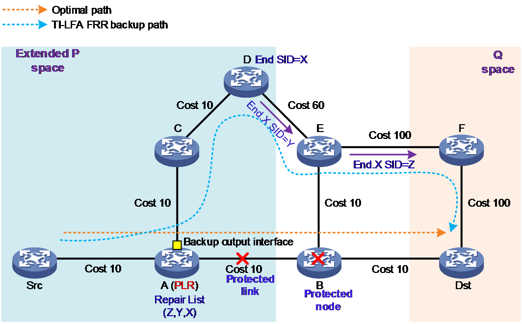
Under default conditions of TI-LFA FRR algorithm, it typically calculates the FRR backup path for the node protection. The calculation process is as follows:
1. The PLR node calculates a FRR backup path for traffic heading towards the destination node Dst. The PLR treats the directly connected next hop node on the optimal path as a fault node and excludes it. It then calculates the optimal path after the fault converges, which is A→C→D→E→F→Dst.
2. Calculate the extended P space: Use the RLFA FRR algorithm to calculate the extended P space for the protected node B. The P node includes Src, A, C, and D.
3. Calculate Q space: Use the RLFA FRR algorithm to calculate the Q space for the protection node B. The Q node includes Dst and F. At this moment, the extended P space and Q space have no intersection.
4. Calculate the repair list: The repair list is used to restrict the forwarding path of messages, preventing loop issues during the message forwarding process. At this moment, the repair list includes the End SID (X) of the last node D in the expanded P-space on the optimal path after fault convergence, the End.X SID (Y) of the D→E link, and the End.X SID (Z) of the E→F link.
5. Calculate the backup egress interface: The message egress interface on the PLR node in the optimal path after convergence.
The TI-LFA FRR backup path calculated above can protect both node B and the link between A and B simultaneously. The PLR writes this TI-LFA FRR backup path into the FIB forwarding table.
But if you remove node F from the topology shown in Figure 5, turning it into the topology shown in Figure 6, the TI-LFA FRR algorithm cannot compute an FRR backup path to protect node B. At this moment, the TI-LFA FRR algorithm continues to calculate the FRR backup path to protect the link A→B.
Figure 6 TI-LFA FRR link protection network
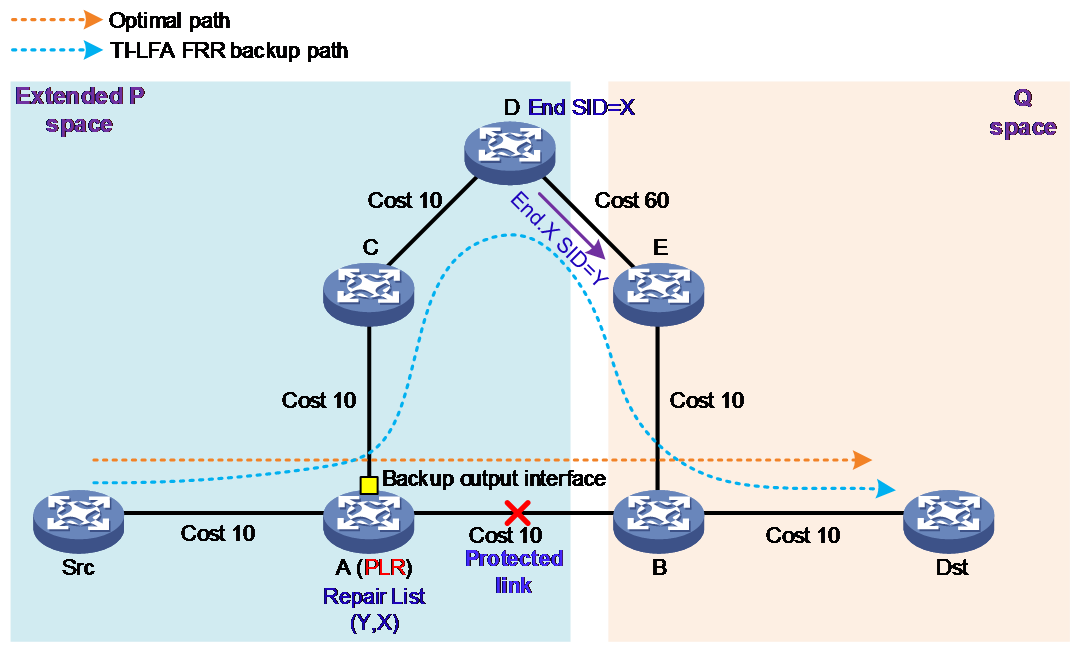
The calculation process for TI-LFA FRR to determine the FRR backup path for protecting the link from A to B is as follows:
1. The PLR node calculates an FRR backup path for traffic going to the destination node Dst. The PLR considers the directly connected link on the optimal path as a faulty link and excludes it to compute a post-fault converging optimal path, i.e., A→C→D→E→B→Dst.
2. Calculate the extended P space: Refer to the RLFA FRR algorithm, calculate the extended P space for the protected link A→B, the P nodes include Src, A, C, and D.
3. Calculate Q space: Refer to RLFA FRR algorithm, calculate the Q space for the protected link A→B. The Q nodes include Dst, B, and E. At this point, the expansion of space P and space Q have no intersection.
4. Calculate the repair list: At this point, the repair list includes the End SID (X) of the last node D in the expanded P space on the optimal path after fault convergence, and the End.X SID (Y) of the D→E link.
5. Calculate the backup egress interface: The outgoing interface for messages on the PLR node in the optimal path after convergence.
The calculated TI-LFA FRR backup path can protect the link between A and B. The PLR writes this TI-LFA FRR backup path into the FIB forwarding table.
TI-LFA FRR forwarding process
After TI-LFA FRR finishes backup path calculation, traffic will be switched to the backup path in response to a primary path failure.
Figure 7 TI-LFA FRR backup path forwarding workflow
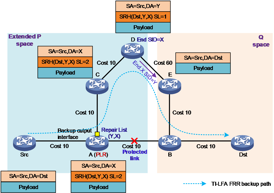
As shown in Figure 7, the TI-LFA FRR function is turned on at node A. When a fault occurs in the link between A and B, it triggers a switchover to the backup path. The following are the detailed steps:
1. The source node transmits an IPv6 packet, with Src as the source address and Dst as the destination address. The source node searches the IPv6 FIB table and forwards the packet to the next hop A.
2. Node A (PLR): After receiving an IPv6 package, node A discovers a fault in the primary path to the next hop, node B. Node A uses the TI-LFA FRR backup path to forward the package, inserting an SRH extension header into the original IPv6 package. The SRH contains a SID list, which includes the original destination address (Dst) and the repair list (Y, X) for the TI-LFA FRR backup path. The SL is set to 2. Node A updates the destination address DA=X based on the SRH, and forwards the packet to C from the backup interface of A→C.
3. Node C: The destination address of the received SRv6 packet is X. Since X is not a local SID, the IPv6 FIB table is searched. The packet is then forwarded to the next hop D according to the normal IPv6 packet forwarding process.
4. Node D: The destination address of the received SRv6 packet is X, which is the End SID in the local SID list. Then, it decreases SL by 1 and updates the destination address DA to Y. The Y is the End.X SID in the local SID list. The node subtracts 1 from the SL and updates the destination address (DA) to Dst. At this point, SL is 0. Node D removes the SRH expansion header from the packet. The D node forwards the packet from the interface corresponding to End.X SID according to the forwarding action associated with End.X SID, sending it through the D to E interface.
5. Node E: The destination address of the received packet is Dst. The node looks up the IPv6 FIB table to forward the packet to destination node Dst according to the normal IPv6 packet forwarding process. At this point, packet forwarding on the backup path is successful.
|
|
NOTE: The administrator can configure the packet encapsulation method for TI-LFA FRR. The packet encapsulation method for TI-LFA FRR supports both Insert and Encaps methods. You will only explain the packet encapsulation and forwarding process by using the default Insert method. By default, TI-LFA FRR adopts the Insert encapsulation mode to add a repair list as follows: · For SRv6 packets: A new SRH, including all the SID information from the repair list, is inserted between the original IPv6 basic header and SRH. · For regular IPv6 packets: replace the destination address of the original IPv6 base header with the first SID in the repair list, and add SRH. The SRH contains all SID information from the repair list. Configure TI-LFA FRR with Encap encapsulation mode to add a repair list, which means encapsulating a new IPv6 base header and SRH based on the original packet. · The destination address of the IPv6 basic header is the first SID in the repair list, and the source IPv6 address is manually specified by the user. · The SRH includes all the SID information contained in the repair list. |
SRv6 microloop avoidance
In a full mesh network environment, the IGP protocol might generate a loop during unordered convergence. But this loop will disappear after all devices on the forwarding path have completed convergence. This transient loop is known as a microloop. Microloops might cause a series of issues such as network packet loss, delay jitter, and packet disorder.
SRv6 microloop avoidance uses a method that minimizes the impact on the network to eliminate potential loops in the network. The working mechanism of SRv6 microloop avoidance is as follows: If a network topology change causes a loop, the network node creates a loop-free SRv6 segment list to direct traffic forwarding to the destination address. Once all network nodes have completed convergence, it reverts back to the normal forwarding state, effectively eliminating any loops in the network.
Microloop avoidance upon network failure
This feature addresses temporary loops generated when nodes have different convergence time sequences when switching from the pre-convergence path to the post-convergence path.
As shown in Figure 8, node A is the source node, node B is the fault node, and node C is the destination node. The values in the link indicate the cost values. All nodes have the TI-LFA FRR feature enabled, and TI-LFA FRR calculated a FRR backup path that protects node B: A→D→E→F→C.
When B node encounters a fault, the traffic from A node to C will switchover to the backup path computed by TI-LFA for forwarding.
1. Node A detects a fault and enters the FRR switchover process of TI-LFA. It inserts a repair list <e> into the packet and redirects the message to the PQ node E calculated by TI-LFA. Therefore, the packet will be first forwarded to the next hop node D. At this moment, the SID in the segment list is: <c, e>.
2. When node A completes the route convergence to the destination address C, it directly searches for the route of node C, forwards the packet to the next hop node D, and no longer carries the repair list. Instead, it forwards the packet based on destination address c directly.
3. If node D has not yet completed convergence at this point, when node A forwards the packet to node D, the next hop to node C in node D's forwarding table is still node A. This forms a loop between node A and node D.
Figure 8 Microloop avoidance upon network failure
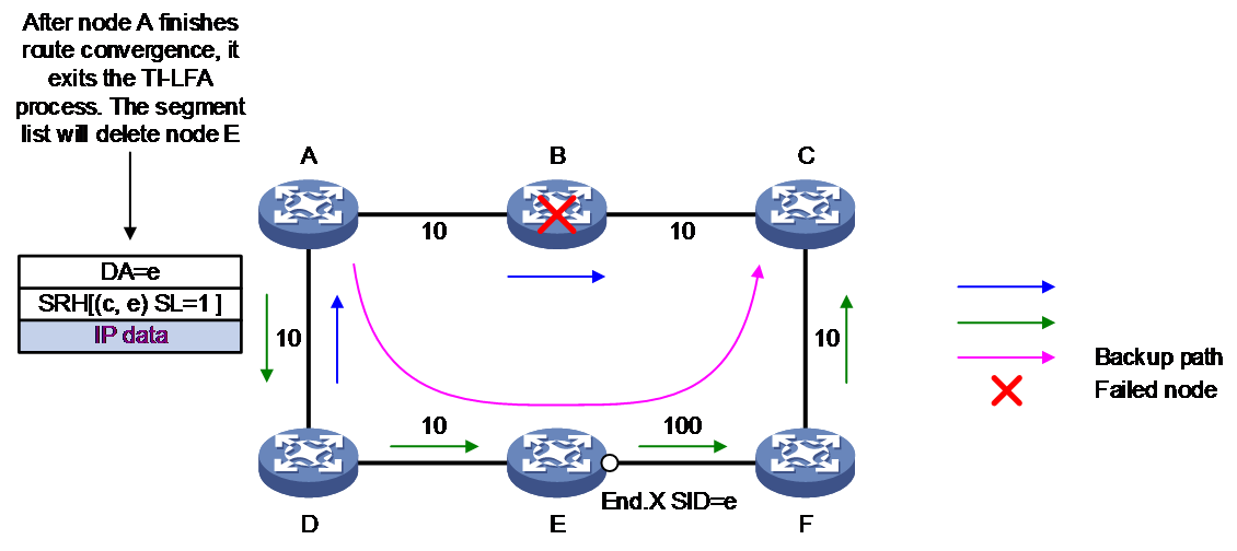
A microloop occurs when node A completes convergence, exits the TI-LFA process, and performs normal forwarding, while other nodes in the network have not yet completed convergence. Therefore, the loop issue in this scenario can be resolved by simply delaying the convergence of node A. Because the TI-LFA path is always loop-free, it just needs to forward according to the TI-LFA path for a certain period of time. Once the other nodes in the network have finished convergence, they can exit the TI-LFA, avoiding microloops upon failure.
As shown in Figure 8, when microloop avoidance upon failure is deployed on all nodes, the convergence process after node B faults is as follows:
1. Node A detects a fault and enters the TI-LFA process. The packet is forwarded along the backup path, the next hop is Node D, and the repair list <e> is encapsulated.
2. Node A starts a timer. Before the timer expires, node A does not respond to topology changes, the forwarding table remains the same, and packets are still forwarded according to the TI-LFA policy. Other nodes in the network are converging correctly.
3. The timer of Node A times out when all other nodes in the network have finished convergence. Node A converges correctly as well, exits the TI-LFA process, and forwards the packets according to the path after normal convergence.
Microloop avoidance upon failure recovery
When the optimal path becomes available after the fault node or link is restored, and the service switches from the current non-optimal path to the restored optimal path. However, different nodes converge at different times, leading to a temporary loop issue.
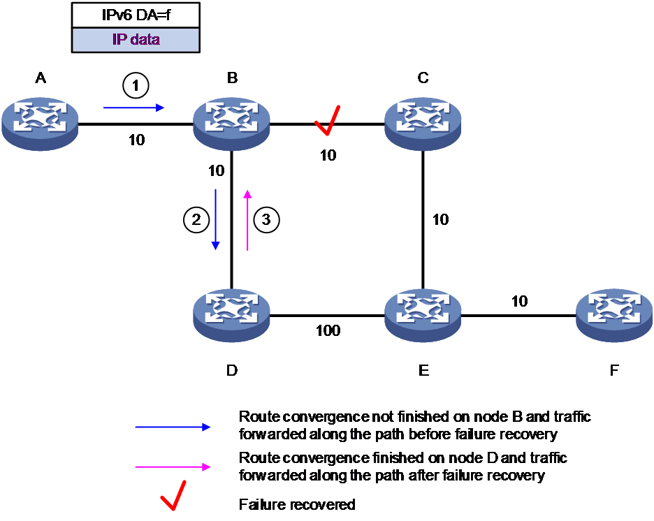
As shown in Figure 9, after the link fault recovery between node B and node C, a loop might occur between node B and node D. The loop generation process is as follows:
1. Node A transmits the packet following the path A→B→C→E→F to the destination node F. After the link between B and C develops a fault, node A will transmit the packet to the destination node F along the recalculated path A→B→D→E→F.
2. After the link fault between node B and node C is restored, if node D completes the convergence first, node A will forward the packet to node B. However, since node B has not completed convergence, it continues to forward along the path before the switch-back, forwarding to node D.
3. Node D has finished convergence, so node D forwards according to the switch-back path to node B, and a loop is generated between node B and node D.
Figure 9 Microloop avoidance upon failure recovery scenario
To solve the microloop avoidance upon failure recovery issue, node D needs to construct a strictly explicit path through SRH upon the completion of route convergence. This ensures that the packet from the node D passes through the post-failure recovery link to the destination node F without forming a loop. When constructing a loop-free path, there is no need to specify the path from node D to node B. Node C will not be affected by the Up event of the B-C link, and the path from Node C to F will definitely be a loop-free path. The only affected is the path from node B to node C, so to calculate the loop-free path from node D to node F, you only need to specify the path from node B to node C. Based on the above analysis, all you need to do is to insert an End.X SID instruction packet from node B to node C in the path after node D converges. This ensures that the path from node D to node F is without a loop. However, in reality, node D cannot predict which specific link will be used for switch-back. For example, if the switch-back link is between node C and node E, an End.X SID from node C to node E needs to be inserted into the path after node D converges. Therefore, the strict explicit path constructed by the D-node must include all End.X SIDs between the neighbor node and the destination node on the optimal path after convergence.
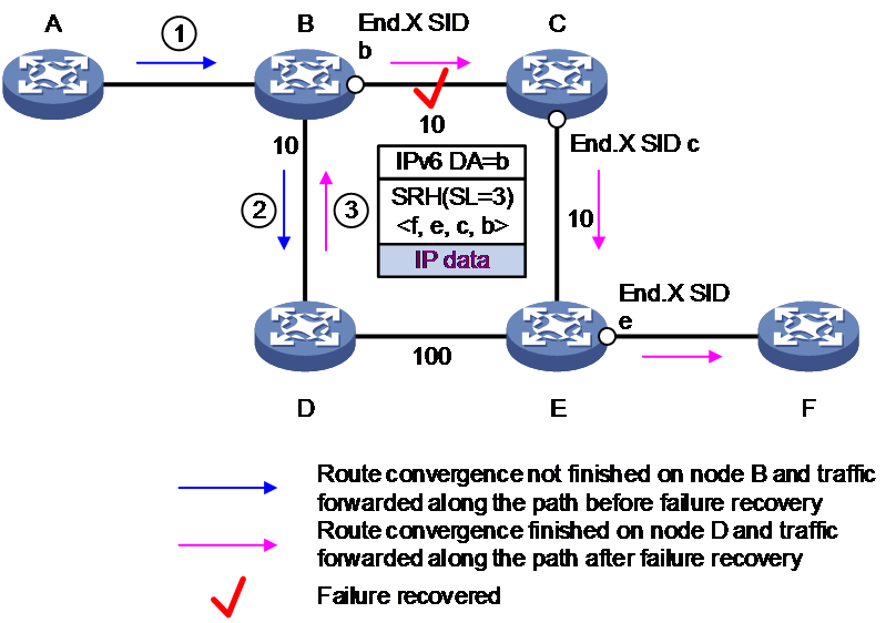
As shown in Figure 10, the convergence process after deploying microloop avoidance upon failure recovery is as follows:
1. After the link fault between node B and node C is recovered, node D is the first to complete convergence.
2. Node D initiates a timer. Before the timer times out, Node D calculates the microloop avoidance segment list for the packet accessing Node F as <e, c, b>.
3. Node A forwards the packet to Node B. As Node B has not finished convergence, it still forwards the packet to Node D following the path it used before the switch-back was done.
4. Node D inserts a microloop avoidance segment list <e, c, b> to the packet and forwards this packet to node B.
5. Node B executes the forwarding action according to the End.X SID b instruction: That is, it forwards the packet to Node C through the egress interface specified by End.X SID b and decreases SL by 1.
6. Node C and Node E forward the packet to the destination node F according to the segment list.
Figure 10 Microloop avoidance upon failure recovery
SRv6 intermediate node protection
Scenario of TI-LFA FRR Failure
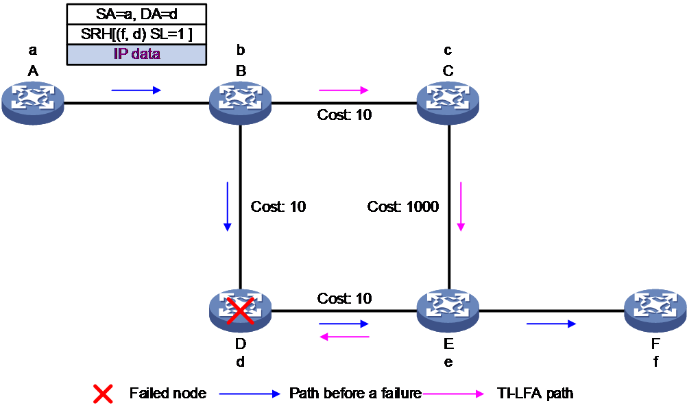
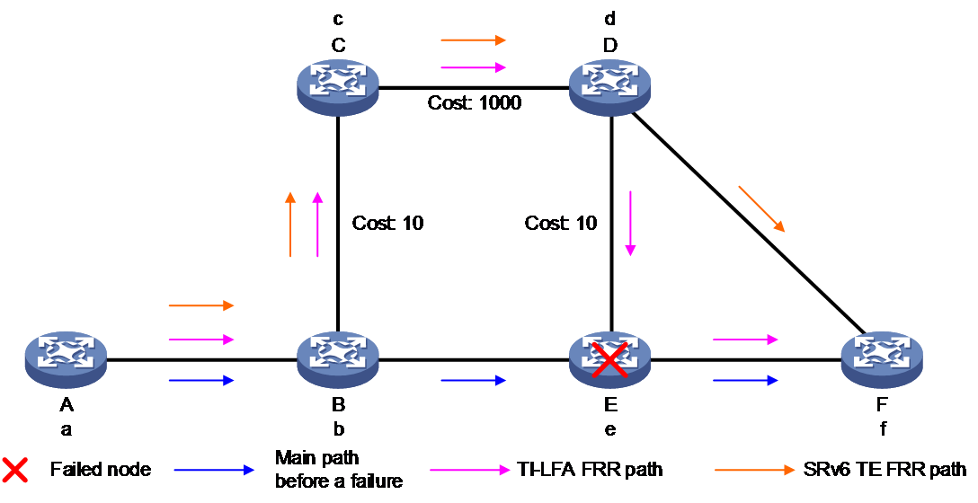
An SRv6 TE policy does not always require constraining the forwarding path of packets in the network. You need to specify the nodes or links that the packet passes through on its way. As shown in Figure 11, Node A needs to transmit a packet to Node F, and the required forwarding path must go through Node D. When node D is faulty, the protection effect of TI-LFA FRR cannot be achieved since the backup path still needs to go through node D.
Figure 11 TI-LFA failure scenario
Intermediate node protection in SRv6
To solve the problem of TI-LFA FRR protection failure in SRv6 TE policy scenario caused by strict node constraints, you need to configure a proxy forwarding node for the forwarding process, which is the upstream node intermediate node in this scenario. When the proxy forwarding node detects a fault in the interface of the next hop of a packet, and the next hop is the destination address of the packet, and SL>0, it takes over as the intermediate node to decrement SL by one. It updates the SID to be processed at the next layer to the outer IPv6 packet header, then forwards the packet according to the instructions of the lower layer SID. This allows it to bypass the faulty node, achieving protection against faults in SRv6 intermediate nodes.
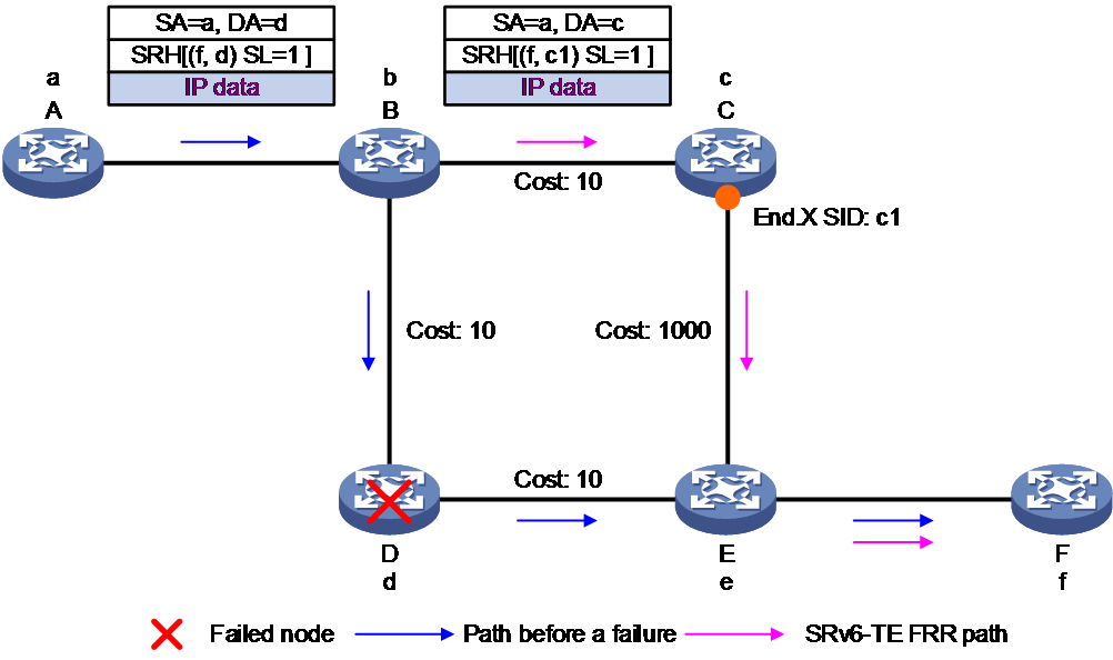
For example, as shown in Figure 12, node A forwards the packet to the destination node F, specifying that it will pass through the intermediate node D in the SRH. When node D encounters a fault, the protection process for a faulty intermediate node in SRv6 is described as follows:
1. When node D encounters a fault, its upstream node B detects that the next hop node has a fault, and the next hop is exactly the current destination address d of the packet. At this time, SL > 0, so node B executes proxy forwarding action, subtracts 1 from SL, and copies the lower-layer SID f to the destination address field of the outer IPv6 packet header. At this point, since SL=0, node B can remove the SRH expansion packet header, and then forward the packet based on routing table lookup for destination address f.
2. As the primary next hop for destination address f remains node E, but node B is not the penultimate hop for this destination address and SL=0, node B no longer meets the proxy forwarding condition. Instead, it switches to the normal TI-LFA forwarding process, forwarding through the backup path. The repair list of the backup path is <c1>, so node B encapsulates the segment list for the packet, and forwarding it to node F through the backup path.
3. When node A detects a fault in node D and IGP has completed convergence, node A deletes the route forwarding entry to node D. Hence, node A cannot match the route when forwarding based on d. At this point, node A acts as a proxy forwarding node and executes the proxy forwarding action, reducing the SL by 1 and updating the next layer SID f onto the outer IPv6 packet header. Then, it forwards the packet based on the destination address f to node B. If node B has converged, it forwards the packet to node F along the shortest path after convergence. If node B has not converged, it forwards the packet to node F through the backup path following the TI-LFA process. By using the above-mentioned method, the faulty node D is bypassed.
Figure 12 Fault protection for intermediate nodes in SRv6
Difference between intermediate node protection and TI-LFA FRR
As shown in Figure 13, node A transmits a packet carrying segment list <e, f>. Since TI-LFA FRR calculates a backup path based on the destination address of the packet, the backup path computed by TI-LFA also passes through node E. If node E has a fault, TI-LFA FRR cannot implement protection. In SRv6, the protection of the intermediate nodes is calculated based on the underlying SID backup forwarding path. Therefore, it can bypass the faulty intermediate node E, achieving intermediate node protection for the SRv6 TE policy.
Figure 13 Differences between intermediate node protection and TI-LFA FRR
Endpoint protection of SRv6
Application scenario of endpoint protection in SRv6
In the IP L3VPN/EVPN L3VPN/EVPN VPLS/EVPN VPWS over SRv6 TE policy network, the public network tunnel is an SRv6 TE policy tunnel. If the endpoint of the SRv6 TE policy fails, it will cause packet forwarding to fail. Therefore, protection needs to be provided for the endpoint of the SRv6 TE policy.
The SRv6 TE policy endpoint protection is applicable only to dual-homing network scenarios, and it requires that the endpoint and the protection node have the same forwarding table entries.
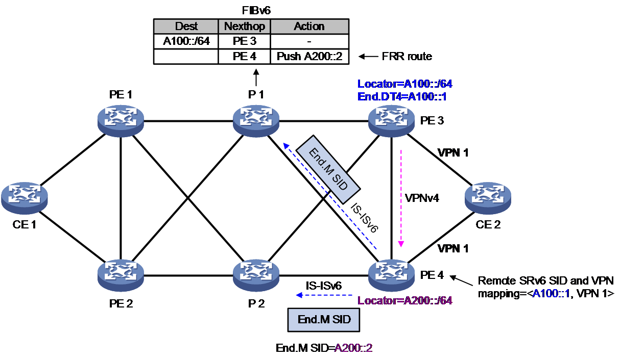
As shown in Figure 14, an SRv6 TE policy is deployed between PE 1 and PE 3. PE 3 is the endpoint of the SRv6 TE policy. To enhance reliability, PE 4 provides protection for PE 3.
Figure 14 Endpoint node protection in SRv6 TE policy
End.M SID
In the scenario of endpoint protection in SRv6 TE policy, the End.M SID is used to protect a specified locator, that is, to guard the SRv6 SID within the specific locator section. If an SRv6 SID advertised by a remote device is within the locator, the protection node uses the End.M SID to protect that SRv6 SID. In different network environments, the forwarding actions corresponding to End.M SID vary.
· In the scenario of IP L3VPN over SRv6 TE/EVPN L3VPN over SRv6 TE end-node protection, the forwarding action corresponding to the End.M SID is to remove the outer IPv6 packet header, and obtain the information of the inner packet. The destination IPv6 address of the inner packet is used as the remote SRv6 SID. The device looks up the mapping table of the remote SRv6 SID and the VPN instance to find the corresponding VPN instance. Then, it forwards the information by querying in the routing table of that VPN instance.
· In the EVPN VPWS over SRv6 TE endpoint protection scenario: The forwarding action corresponding to the End.M SID is to remove the outermost layer of the IPv6 packet header and obtain the information of the inner packet. The destination IPv6 address of the inner packet serves as the remote SRv6 SID. The device searches the mapping table of the remote SRv6 SID and cross-connect to find the corresponding cross-connect. It sends the packet through the AC associated with this cross-connect.
· In the EVPN VPLS over SRv6 TE endpoint protection scenario: The forwarding action corresponding to the End.M SID is to remove the outer IPv6 packet header and obtain the inner packet information. The destination IPv6 address of the inner packet serves as the remote SRv6 SID. The device searches the mapping table of the remote SRv6 SID and the VSI to find the corresponding VSI. Then, it looks up the MAC address table of this VSI to forward the packet.
Remote SRv6 SID
As shown in Figure 14, after PE 4 receives a BGP route from PE 3, if the SRv6 SID in the BGP route falls within the range of the End.M SID protection on PE 4, then the SRv6 SID is considered a remote SRv6 SID. Meanwhile, a mapping table of the remote SRv6 SID to the VPN instance/cross-connect/VSI is generated on PE 4.
When PE 3 has a fault, the neighbor connection between PE 4 and PE 3 is disrupted, which causes the BGP routes received by PE 4 from PE 3 to be deleted. This, in turn, leads to the deletion of the mapping table of remote SRv6 SID and VPN-instance/cross-connect/VSI, resulting in packet loss. To avoid the situation, you can delay the deletion of the mapping table of remote SRv6 SID and VPN instance/cross-connect/VSI on PE 4. This ensures that traffic is forwarded through PE 4 before PE 1 detects the fault of PE 3 and calculates a new forwarding path, preventing packet loss.
Route advertisement
The processes of advertising routes in scenarios of IP L3VPN/EVPN L3VPN/EVPN VPWS/EVPN VPLS over SRv6 TE node protection are similar. This example describes the IP L3VPN over SRv6 TE node protection scenario.
As shown in Figure 14, the generation process of the FRR path on P1 is as follows:
1. PE 4 uses IPv6 IS-IS to advertise the End.M SID and the protected Locator to its neighbor P 1, while generating a local SID table for the End.M SID on PE 4.
2. Upon receiving a route carrying the End.M SID, it generates FRR route information to the specified locator, with the action being to deployed the End.M SID. The forwarding path corresponding to this FRR route is the Mirror FRR path.
As shown in Figure 14, the process of generating the remote SRv6 SID to VPN instance mapping table on PE 4 is as follows:
1. After receiving the private route advertised by CE 2, PE 3 encapsulates it into a VPNv4 route and transmits it to PE 4. The route carries SRv6 SID, RT, and RD information.
2. After receiving the VPNv4 route from PE 3, PE 4 obtains the corresponding SRv6 SID for the VPN instance. PE 4 uses the SRv6 SID and End.M SID-protected locator section for the longest match. If a match is found, the SRv6 SID becomes the remote SRv6 SID. A mapping table of the remote SRv6 SID with the VPN instance is then generated on PE 4.
Packet forwarding
The packet forwarding processes for IP L3VPN/EVPN L3VPN/EVPN VPWS/EVPN VPLS over SRv6 TE endpoint protection scenarios are similar. This example describes the IP L3VPN over SRv6 TE tail-end protection scenario.
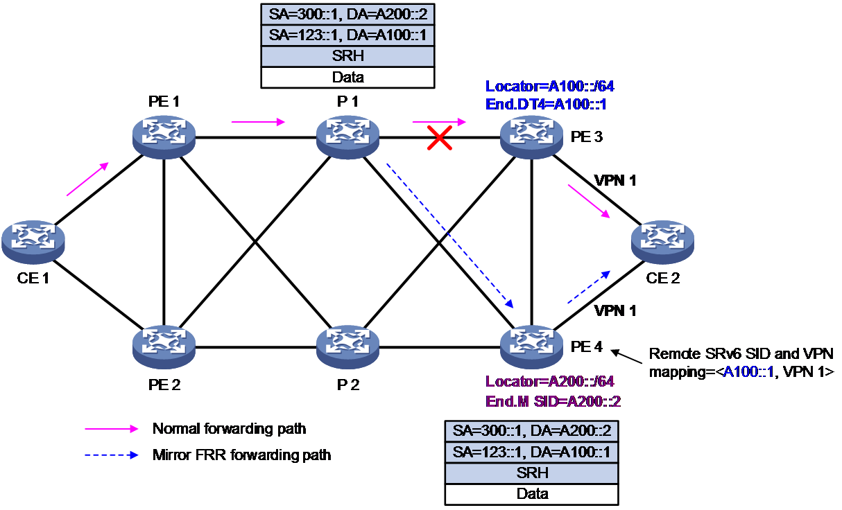
As shown in Figure 15, in normal conditions, the traffic is forwarded through the path CE 1-PE 1-P 1-PE 3-CE 2. When the endpoint PE 3 is faulty, the packet forwarding process is:
1. P 1 detects that the next hop PE 3 is unreachable, and switches to the FRR path. P 1 encapsulates an IPv6 header with a destination address of End.M SID, and then forwards it to PE 4.
2. After receiving the message, PE 4 searches the local SID table and matches it to the End.M SID. PE 4 executes the forwarding action corresponding to End.M SID, which is to decapsulate the packet and obtain the information contained in the inner packet. The destination IPv6 address of the inner packet is taken as the remote SRv6 SID. It searches the mapping table of the remote SRv6 SID and VPN instance to find the corresponding VPN instance 1. Then, it looks up the routing table of VPN instance1 on PE 4 to forward the packet to CE 2.
Figure 15 Endpoint protection packet forwarding of SRv6 TE policy
Related documentation
draft-ietf-rtgwg-segment-routing-ti-lfa-05