| Title | Size | Downloads |
|---|---|---|
| Microsegmentation Technology White Paper-6W100-book.pdf | 462.86 KB |
- Table of Contents
- Related Documents
-
| Title | Size | Download |
|---|---|---|
| book | 462.86 KB |
Microsegmentation Technology White Paper
Copyright © 2024 New H3C Technologies Co., Ltd. All rights reserved.
No part of this manual may be reproduced or transmitted in any form or by any means without prior written consent of New H3C Technologies Co., Ltd.
Except for the trademarks of New H3C Technologies Co., Ltd., any trademarks that may be mentioned in this document are the property of their respective owners.
This document describes only the most common information for lightning protection. Some information might not be applicable to your products.
Contents
Microsegmentation implementation
Network endpoint joining the microsegment
Create an ACL based on microsegmentation
Technical features implemented by Comware
A single group corresponds to a single VXLAN gateway
A single group corresponds to multiple VXLAN gateways
Multiple groups correspond to a single VXLAN gateway
Relationship between aggregation microsegmentation ID and regular microsegmentation ID
Typical application of EVPN VXLAN data center network
Typical application of EVPN VXLAN in campus network
Overview
Technical background
In traditional data center networks, dedicated firewall devices are typically deployed at the network boundary to analyze traffic entering the data center network (i.e., north-south traffic), ensuring that only legitimate traffic is allowed in, thus protecting the data center network from external network attacks.
Figure 1 Traditional data center network
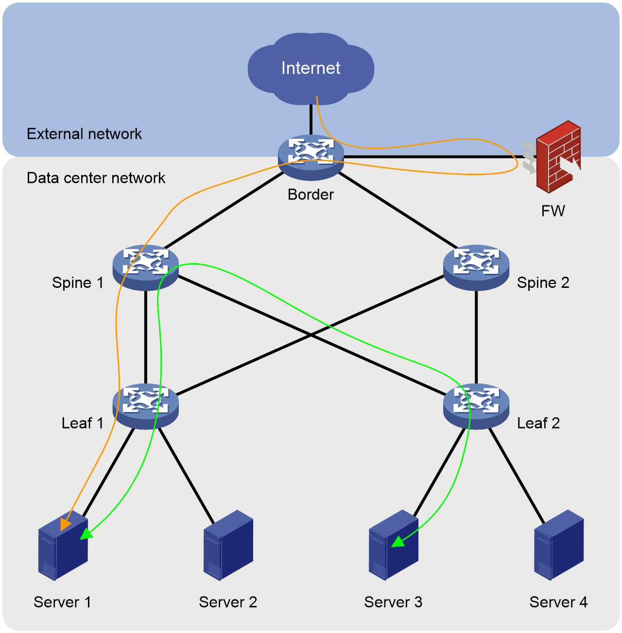
Once an attack from the external network breaks through the firewall, the security of the data center network will be severely threatened, allowing the attacker to freely attack servers within the data center network. With the continuous development of data centers, traffic within the data center network (east-west traffic) is also increasing, requiring security protection. Therefore, in the new generation of data center networks, how to strengthen the security management of north-south traffic and how to implement security control on east-west traffic has become an urgent problem to be solved. This is where microsegmentation technology was born.
Benefits
Microsegmentation groups network endpoints (e.g., servers in data centers, virtual machines, or online users on various terminals in campuses), deploys policies between the groups, and passes secure control over the communication between network endpoints belonging to different groups through inter-group policies. This operational mechanism determines its advantages, such as fine granularity of control and fewer access control list (ACL) resource demands.
Fine granularity control
Compared to traditional sectioning technologies (VLAN, IP subnet), microsegmentation technology offers finer control granularity.
VLANs or IP subnets can only isolate different VLANs or subnetworks. They cannot isolate network endpoints within the same VLAN or subnet.
At the same time, when different subnets share the same gateway device, the route information to each subnet is stored on the gateway device. In such case, it is impossible to fully implement isolation between different network endpoints within different subnets.
Microsegmentation allows for a more precise grouping based on IP address and IP address section, achieving a more detailed security isolation.
Occupying fewer ACL resources
Compared to traditional security control technologies (mainly ACL), microsegmentation technology can significantly reduce the usage of ACL resources.
Using Access Control Lists (ACLs) can achieve fine-grained security isolation, but the device's own ACL resources are limited, making it difficult to meet business requirements.
Figure 2 Schematic Diagram of ACL Resource Utilization
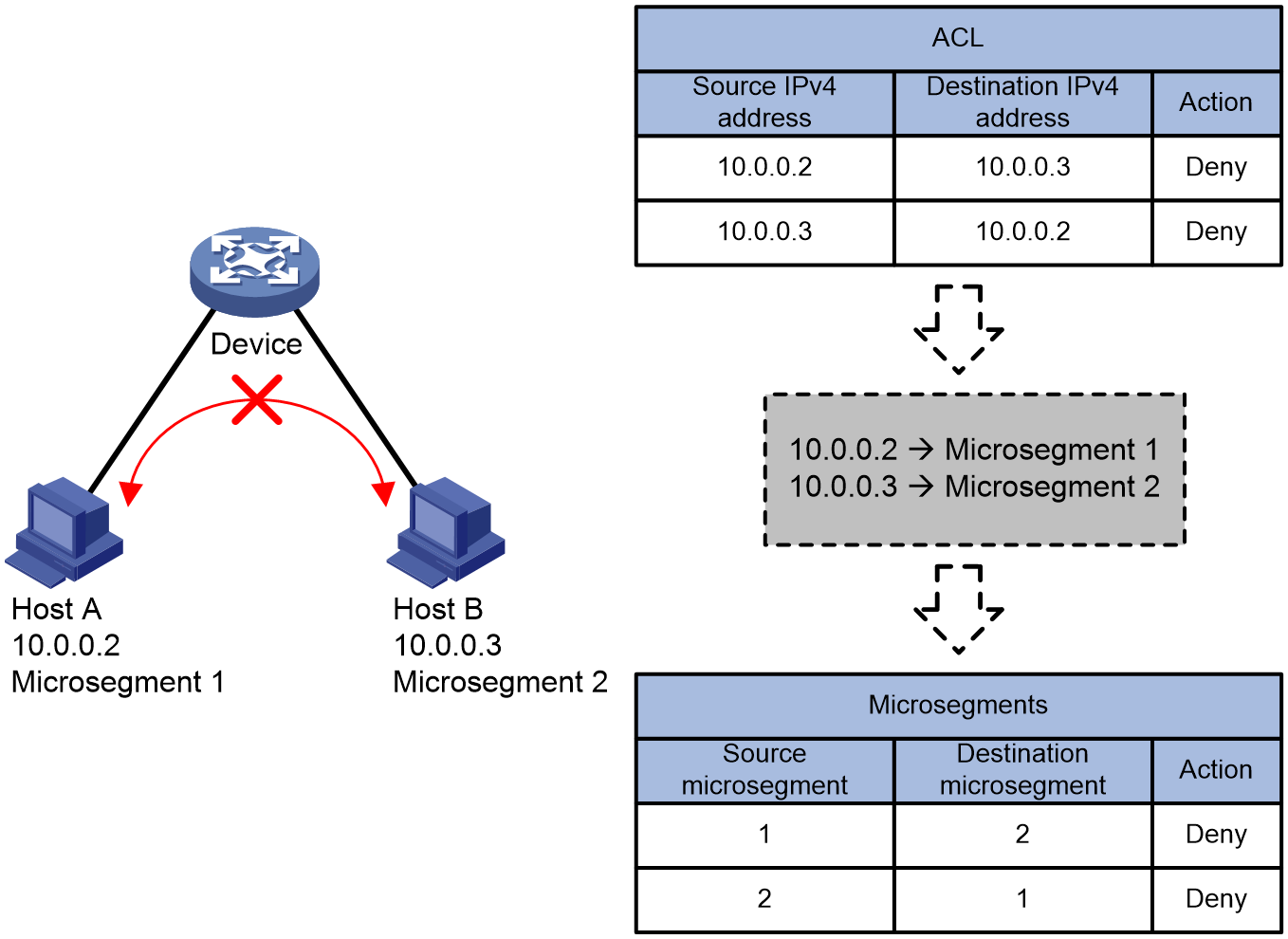
As shown in Figure 2, if you want to prevent Host A and Host B from communicating with each other:
· When using Access Control List (ACL), it's necessary to match the IP address of the packet. The length of an IPv4 address is 32 bits, and matching both source and destination IP addresses requires 64 bits of ACL resources. When controlling bidirectional traffic simultaneously, it requires two 64 bits ACL resources. Meanwhile, with a length of 128 bits, IPv6 addresses demand more ACL resources.
· When using microsegmentation, you only need to match the microsegmentation ID to which the packet belongs. The length of the microsegmentation ID is 16 bits, and the ACL resources required to match the source and destination microsegmentation are only 32 bits. Even when controlling bidirectional traffic, you only need two 32-bit ACL resources.
When the amount of controlled traffic increases, it's simply a matter of adding the new IP address to the existing microsegmentation. The use of ACL resources by microsegmentation does not demonstrate a linear increase.
Microsegmentation implementation
Concepts
Microsegmentation
Microsegmentation is a collection of network endpoints, possessing a globally unique ID, which identifies a microsegment via this ID.
Microsegmentation can be implemented based on IP addresses, network segments, MAC addresses, etc., for network endpoints. This allows network devices to manage control from IP addresses, MAC addresses, etc., to control based on microsegmentation IDs.
GBP
Group Based Policy (GBP) is a traffic control policy based on microsegmentation.
By deploying GBP, secure control can be carried out on communication between network endpoints belonging to different microsegments. However, network endpoints within the same microsegment can interact with each other, with GBP not controlling the traffic within the same microsegment. GBP can be implemented through message filtering, QoS policy (MQC), or policy routing.
Operating mechanism
Source-end control policy
Microsegmentation is a source-end control policy, where the microsegmentation function is configured on the source-end device, achieving secure traffic management.
The microsegmentation function consists of three parts:
1. Include network endpoints in microsegmentation. According to different application scenarios and deployment methods, network endpoints can be included in microsegmentation in the following ways: static IP microsegmentation, static AC microsegmentation, authorization microsegmentation, and route announce microsegmentation.
2. Create an Access Control List (ACL) based on microsegmentation ID.
3. The packet filtering, QoS policy (MQC) or policy routing references ACL to achieve security control over the communication between network endpoints belonging to different microsegments.
Upon completing the aforementioned configurations on the source device, the source device receives a packet. It then finds the matching ACL rule based on the microsegmentation ID of the packet and links to GBP through this ACL rule. GBP enforces traffic control on packets that match the ACL.
In conclusion, microsegmentation is applied to the source device in the message forwarding path. When the GBP decision result is to discard, the message will be directly discarded and will not be further forwarded through the intermediate network to the destination, thus avoiding bandwidth waste.
Figure 3 Source end traffic control schematic diagram
Network endpoint joining the microsegment
Static IP microsegmentation
In IP networks, VXLAN networks, and EVPN VXLAN networks, microsegments can be created manually, and members in the form of IP addresses or IP address sections can be added to the microsegments. This ultimately generates a static IP microsegmentation table as shown in Table 1.
The device finds the static IP microsegmentation table based on the source and destination IP addresses of the received message, obtaining the microsegmentation ID associated with the source and destination IP addresses (that is, the source and destination microsegmentation ID), implementing the conversion of message IP address to microsegmentation ID.
Table 1 Schematic Diagram of Static IP Microsegmentation
|
VPN Instance |
Network Address/Mask Length |
Microsegmentation ID |
|
VPN1 |
10.1.1.0/24 |
100 |
|
VPN1 |
20.1.1.0/24 |
100 |
|
VPN1 |
0.0.0.0/0 |
100 |
|
VPN1 |
1:2::3:4/128 |
100 |
|
VPN2 |
10.1.1.0/24 |
200 |
|
VPN2 |
20.1.1.0/24 |
200 |
|
VPN2 |
0.0.0.0/0 |
200 |
|
Public network |
1:2::3:4/128 |
200 |
Static AC microsegmentation
In a VXLAN network, microsegmentation can be created through manual configuration, and a microsegmentation ID can be assigned to the attachment circuit (AC) of VXLAN, thereby generating a static Port microsegmentation table or a static Port VLAN microsegmentation table. For example, Table 2 demonstrates a static Port VLAN microsegmentation table.
The device finds the static Port VLAN microsegmentation table based on the ingress interface and corresponding VLAN of the received packets, obtains the related microsegmentation ID, and implements the translation from the packet's ingress interface and VLAN to the microsegmentation ID.
Table 2 Static port VLAN microsegmentation
|
AC |
Port |
VLAN |
Microsegmentation ID |
|
AC1 |
Gigabit Ethernet Port 1/0/1 |
3501 |
101 |
|
AC2 |
Gigabit Ethernet 1/0/1 |
3502 |
102 |
|
AC3 |
GigabitEthernet1/0/1 |
3503 |
103 |
Authentication authorization microsegmentation
In the campus network, microsegmentation can be used to represent user roles or permission groups, and devices control user access rights through microsegmentation.
Users who go online through authentication methods such as 802.1X or MAC address will be authorized with a microsegmentation ID (carried by the User Group authorized by the authentication system). All user traffic will be tagged with the authorized microsegmentation ID, ultimately establishing a mapping between the MAC address and the microsegmentation ID.
Table 3 Authentication authorization microsegmentation
|
User (MAC address) online. |
Microsegmentation ID |
|
User A |
101 |
|
User B |
101 |
|
User C |
102 |
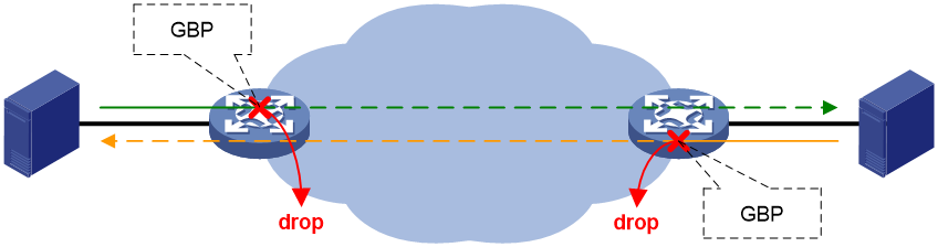
Route announcement implements microsegmentation
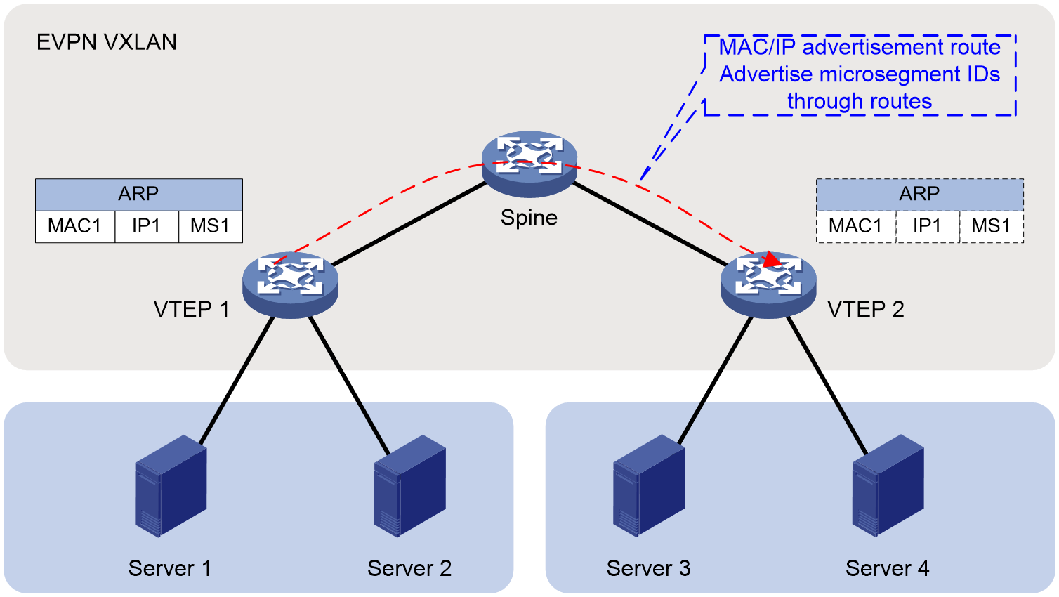
In the EVPN VXLAN network, the route announce microsegmentation function is used to announce the microsegmentation information (Info) configured on this endpoint VTEP (VXLAN tunnel endpoint) to the opposite endpoint VTEP, enabling the source end to automatically obtain the microsegmentation of the destination end. Taking Figure 4 as an example, both VTEP 1 and VTEP 2 need to be configured with ACL and GBP, while microsegmentation only needs to be configured on one VTEP. This VTEP will announce the microsegmentation to another VTEP.
In an EVPN VXLAN network, after the local VTEP learns the ARP information, it will announce the ARP information to the remote VTEP through the MAC/IP route release. At this time, for the microsegmentation configured by static IP, static AC or authorization method, the microsegmentation ID corresponding to the IP address OR MAC address can be carried by the BGP extended community attribute of the MAC/IP route release, and the microsegmentation information of the local VTEP is automatically announced to the remote VTEP. After the remote VTEP receives this information, it will be directly effective by adding it to its own ARP table.
Figure 4 Microsegmentation Announcement Diagram
Create an ACL based on microsegmentation
By configuring the ACL rule that matches the source and destination microsegmentation ID, you can generate a microsegmentation traffic control ACL table as shown in Table 4.
Table 4 Microsegmentation traffic control ACL
|
ACL rule ID |
Source Microsegmentation ID |
Purpose Microsegmentation ID |
Action |
|
1 |
101 |
201 |
permit |
|
2 |
201 |
101 |
permit |
|
3 |
101 |
301 |
deny |
|
4 |
301 |
101 |
deny |
|
5 |
10001 |
50001 |
permit |
|
6 |
50001 |
10001 |
permit |
Reference ACL
Associate the microsegmentation traffic control ACL with policy routing, QoS policy OR message filtering to form GBP, which can control traffic between different microsegments. Network endpoints within the same microsegment can access each other, and GBP does not control traffic within the same microsegment.
The source endpoint (Ingress) processes the received packet according to the microsegmentation configuration method, as can be seen in "network endpoint joins microsegmentation", and acquires the Microsegmentation ID of the packet. Next, it controls the packet forwarding based on the preconfigured GBP, as shown in table 5. If the GBP determines the packet should be discarded, the packet is not forwarded to the destination endpoint (Egress); otherwise, the packet is allowed to be forwarded to the destination endpoint.
|
GBP |
Action |
Description |
|
Policy-Based Routing |
Apply the next-hop command to the IP address. |
The action of the policy node is to specify the next hop, indicating that traffic is allowed to pass. |
|
Apply the null0 to the output interface. |
The action of the policy node is to designate NULL0 interface as the egress interface, indicating that traffic flow is prohibited to pass. |
|
|
QoS Policy |
filter permit |
The traffic behavior is configured for traffic filtering, and the action allows the data package to pass, which means that the traffic is allowed to pass. |
|
filter deny |
The traffic behavior is set to traffic filtering, and the action is to discard the data packets, which means that the traffic is prevented from passing through. |
|
|
Packet filtering |
permit |
The action in the ACL rule is permit, which means to allow traffic to pass. |
|
deny |
In the ACL rule, the action is deny, which means traffic is not allowed to pass. |
Process of message forwarding
Static IP microsegmentation
Figure 5 Static IP microsegmentation in a VXLAN network
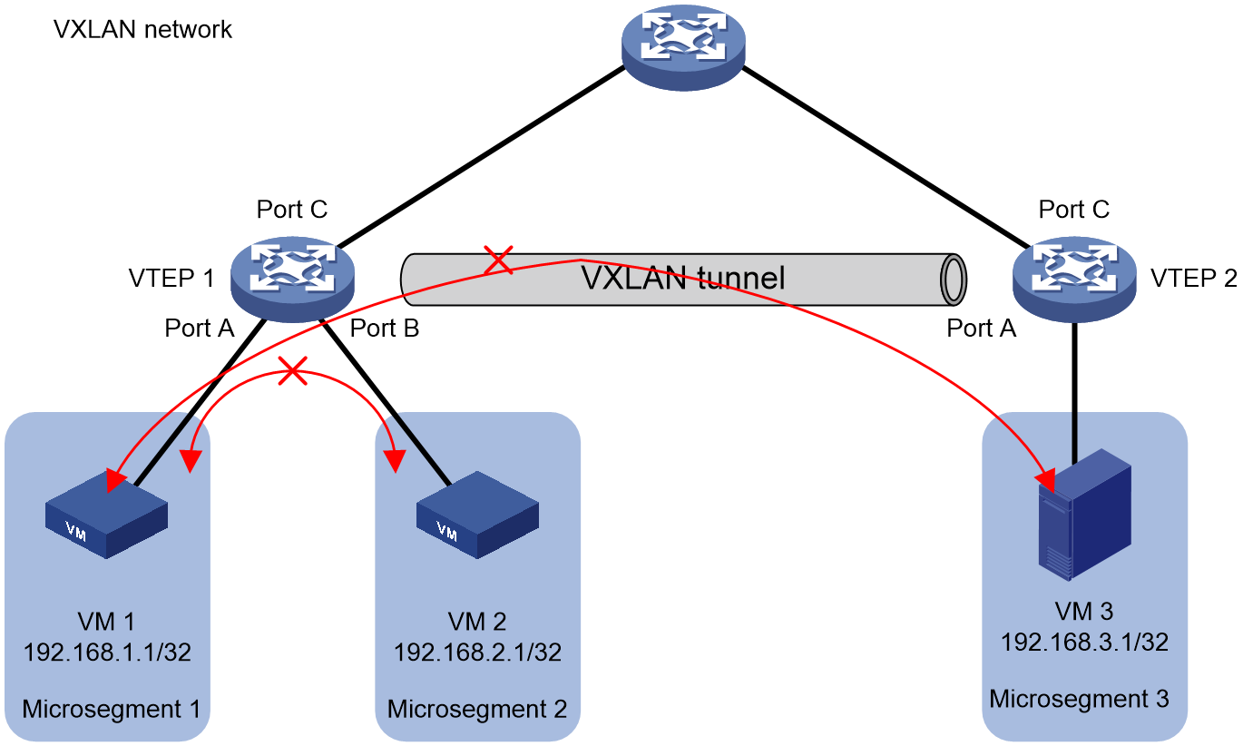
In the VXLAN network depicted in Figure 5, two virtual machines, VM 1 and VM 2, are connected under VTEP 1. Microsegmentation 1 and Microsegmentation 2 are created on VTEP 1, with the IP address (192.168.1.1) of VM 1 added to Microsegmentation 1, and IP address (192.168.2.1) of VM 2 added to Microsegmentation 2. The configuration of microsegments on VTEP 2 is similar to VTEP 1. GBP is deployed separately on VTEP 1 and VTEP 2 to control the mutual access between VM 1 and VM 2, VM 1 and VM 3. Take the traffic from VM 1 to VM 2 for example, the specific running mechanism is:
1. After receiving the packet transmitted from VM 1 to VM 2, VTEP 1 retrieves the source IP address (192.168.1.1) and the destination IP address (192.168.2.1) from the packet.
2. VTEP 1 searches the static IP microsegmentation table according to the source IP address (192.168.1.1), and uses the longest match rule to identify the microsegment to which the source VM 1 belongs (Microsegmentation 1).
3. VTEP 1 uses the longest match rule to search the static IP microsegmentation table based on the destination IP address (192.168.2.1), obtaining the microsegment (microsegment 2) that destination VM 2 belongs to.
4. VTEP 1 obtains the Group Based Policy (GBP) between microsegmentation 1 to which the source-end VM 1 belongs and microsegmentation 2 to which the destination-end VM 2 belongs. It then implements traffic control on the packet based on the GBP.
¡ If the GBP traffic control judgment result allows passage, the message will be transmitted to VM 2.
¡ If the result of GBP traffic control judgement is to ban passage, then discard the message.
Static AC microsegmentation/Authentication authorization microsegmentation
Figure 6 EVPN VXLAN network static AC microsegmentation and authenticated authorization microsegmentation
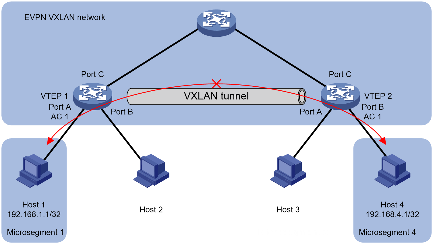
As shown in Figure 6, Host 1 accesses the EVPN VXLAN network through AC 1 of VTEP 1, and Host 4 accesses the same network through AC 1 of VTEP 2. Microsegmentation 1 is created on VTEP 1 and microsegmentation 4 is created on VTEP 2. Host 1 is added to microsegmentation 1 and Host 4 to microsegmentation 4 in the following way. GBP is deployed separately on VTEP 1 and VTEP 2 to control the communication between Host 1 and Host 4.
· For static AC microsegmentation, configure AC 1 to associate with VSI on VTEP 1 and connect AC 1 to microsegmentation 1, thus adding Host 1, which passes through AC 1 to join the EVPN VXLAN network, to microsegmentation 1; VTEP 2 follows the same principle.
· For microsegmentation authorization authentication, when Host 1 goes online, the authentication server sends authorization information to VTEP 1. By carrying the microsegmentation ID in the Usergroup name of the authorization information, Host 1 can be added to microsegmentation 1. The same logic applies to Host 4 under VTEP 2.
The microsegmentation configurations generated at the source end with the two aforementioned methods will be synchronized to other VTEPs through the announcement function of microsegmentation, allowing other VTEPs to automatically obtain the microsegmentation configuration. In this way, information about the microsegmentation ID belonging to Host 1 and Host 4 is present on both VTEP 1 and VTEP 2. As an example, regarding the traffic from Host 1 to Host 4, the specific operation mechanism is:
1. VTEP 1 receives the message transmitted from Host 1 to Host 4.
2. VTEP 1 retrieves the microsegmentation (Microsegmentation 1) corresponding to Host 1.
3. VTEP 1 retrieves the microsegmentation (microsegmentation 4) corresponding to Host 4.
4. VTEP 1 implements traffic control on the packet according to the GBP obtained from the microsegmentation (microsegmentation 1) where Host 1 belongs and the microsegmentation (microsegmentation 4) where Host 4 belongs.
¡ If the verdict of the GBP traffic control allows to pass, then the message will be transmitted to VM 2.
¡ If the result of the GBP traffic control judgment is to forbid passage, then discard the packet.
Technical features implemented by Comware
Flexible grouping
The introduction of the microsegmentation function allows for flexible grouping, facilitating business transformation. Microsegmentation supports a single group corresponding to a single VXLAN gateway, a single group corresponding to multiple VXLAN gateways, and multiple groups corresponding to a single VXLAN gateway. It also supports a single role corresponding to multiple VXLAN gateways in multi-campus application scenarios.
A single group corresponds to a single VXLAN gateway
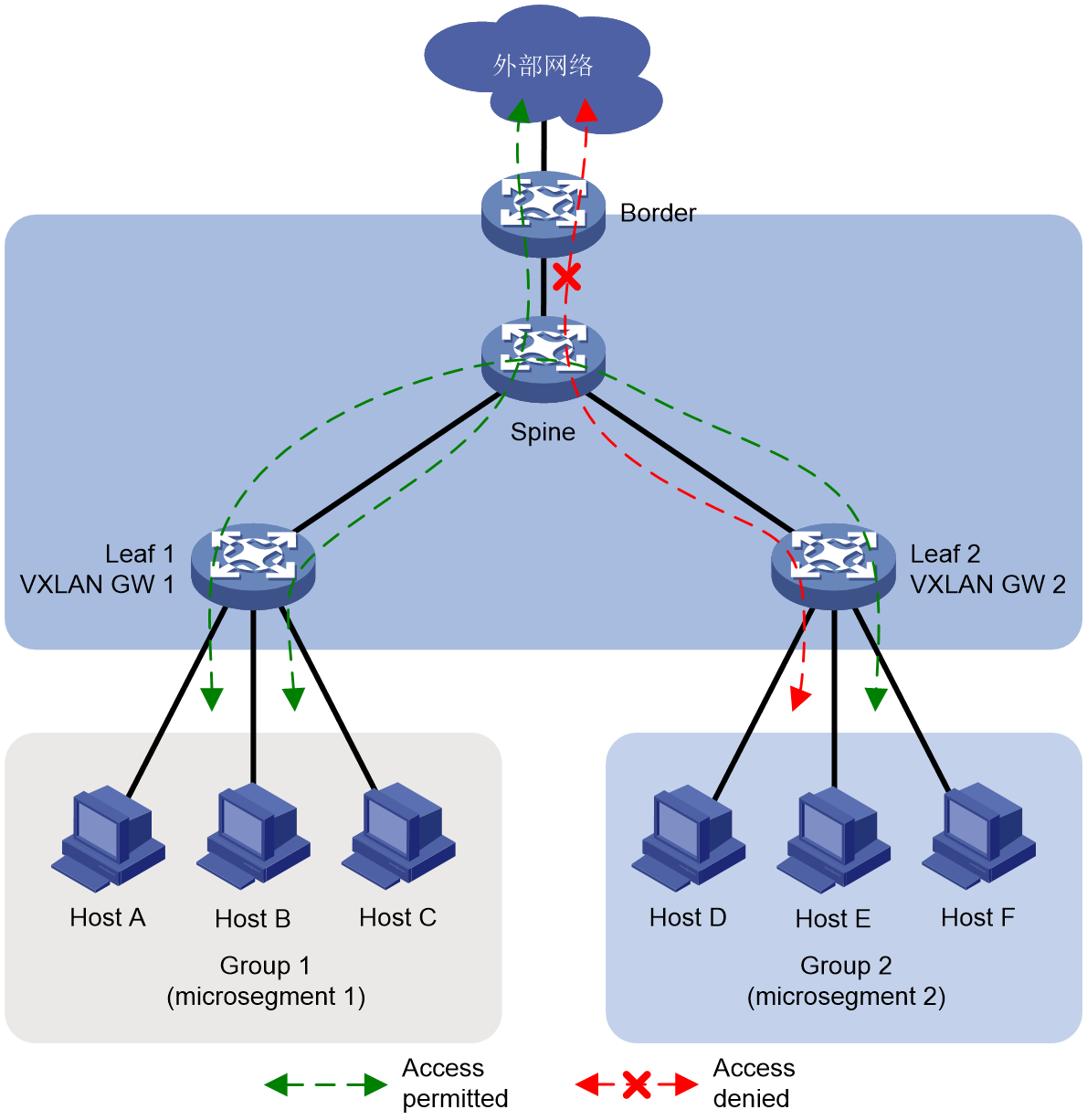
As shown in Figure 7, the VXLAN gateway for Host A to C is Leaf 1 and for Host D to F is Leaf 2. By default, all hosts can interact with each other and with the external network. By deploying microsegmentation, we can flexibly control this interactivity among hosts and between hosts and the external network. For instance, deploying microsegmentation on the VXLAN gateway allows us to assign Host A, B, and C to Group 1 (microsegmentation 1), and Host D, E, and F to Group 2 (microsegmentation 2) - associating a single group with a single VXLAN gateway. Then deploying GBP further allows us to control if interactivity is possible among Group 1, Group 2, and the external network.
Figure 7 Single group corresponding to a single VXLAN gateway
A single group corresponds to multiple VXLAN gateways
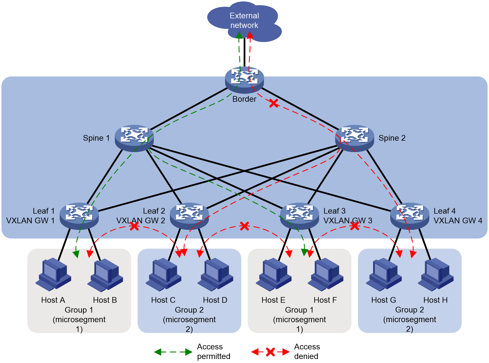
As shown in Figure 8, the VXLAN gateway for Host A and Host B is Leaf 1; the VXLAN gateway for Host C and Host D is Leaf 2; the VXLAN gateway for Host E and Host F is Leaf 3; the VXLAN gateway for Host G and Host H is Leaf 4. By default, hosts can access each other and the external network. By deploying microsegmentation, you can flexibly control the access between hosts and between hosts and the external network. For example, deploy microsegmentation on the VXLAN gateway, and group Host A, Host B, Host E, and Host F into Group 1 (Microsegmentation 1), and Host C, Host D, Host G, and Host H into Group 2 (Microsegmentation 2), where a single group corresponds to multiple VXLAN gateways. Next, deploy GBP to control whether Group 1, Group 2, and the external network can access each other pairwise.
Figure 8 Single group corresponding to multiple VXLAN gateways
Multiple groups correspond to a single VXLAN gateway
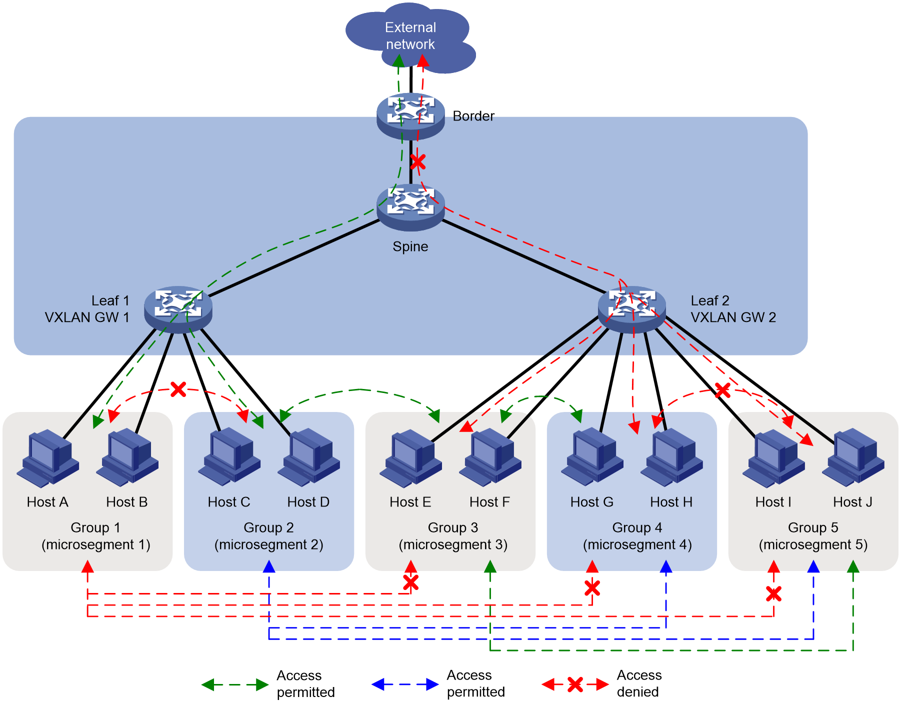
As shown in Figure 9, Host A to D belong to the same network segment with their VXLAN gateway being Leaf 1, and Host E to J belong to another network segment with their VXLAN gateway as Leaf 2. By default, all hosts and external networks can interact with each other. Through the deployment of microsegmentation, it enables flexible control over the interactions among hosts and between hosts and the external network. For instance, by deploying microsegmentation on the VXLAN gateway, it segments Host A and Host B into group 1 (microsegmentation 1), Host C and Host D into group 2 (microsegmentation 2), Host E and Host F into group 3 (microsegmentation 3), Host G and Host H into group 4 (microsegmentation 4), and Host I and J into group 5 (microsegmentation 5). Hence, multiple groups correspond to a single VXLAN gateway. After deploying GBP, it can control whether there is mutual accessibility between any of the groups 1-5 and the external network.
Figure 9 Multiple groups correspond to a single VXLAN gateway
Aggregation microsegmentation
Overview
The Microsegmentation ID is aggregated through a mask, generating a new microsegment, known as an aggregated microsegment. A two-level hierarchy can be formed between the aggregated microsegment and the regular microsegment. Regular microsegments group network endpoints, while aggregated microsegments group regular microsegments based on this. Thus, regular microsegments can inherit the authority of their associated aggregated microsegments, and be assigned special authorities, allowing for finer control.
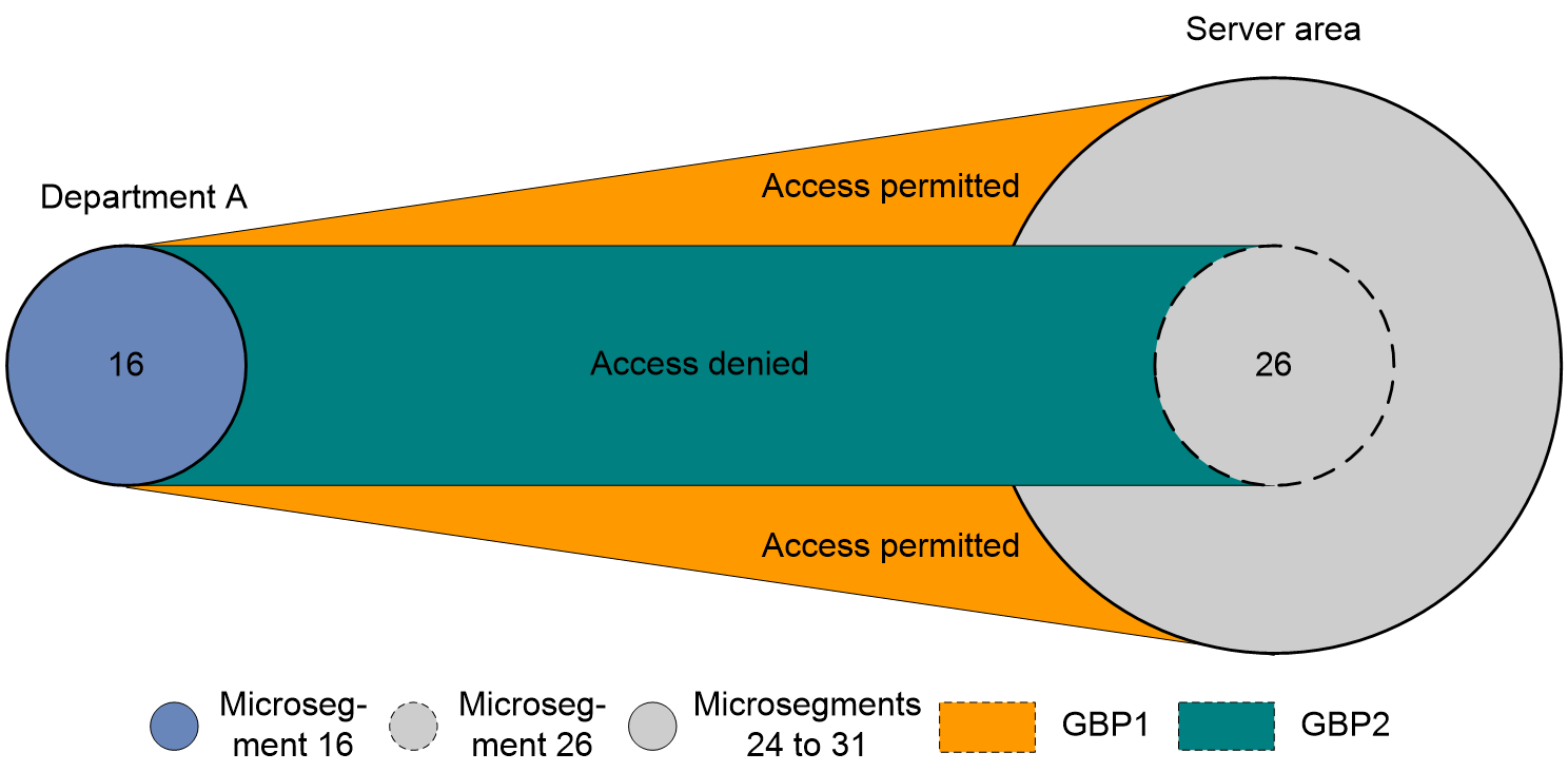
As shown in Figure 10, all users of Department A are assigned to microsegmentation 16, and all servers in the server section are individually assigned to microsegments 24 to 31. Microsegments 24 to 31 are aggregated to create the aggregated microsegmentation 24. GBP 1, which permits interaction between microsegmentation 16 and aggregated microsegmentation 24, along with GBP 2, which prohibits interaction between microsegmentation 16 and 26, are configured. The privilege level of GBP among the groups adheres to the principle of finer preference, i.e., the group with a smaller controlled range (i.e., a lower number of members in the common microsegmentation) has a higher GBP privilege level. In Figure 10, the order of GBP privilege levels is GBP 2 > GBP 1. By configuring these microsegments and aggregated microsegments, all users in Department A are allowed to access most servers in the server section, while access is restricted to some high-density servers in microsegmentation 26.
Figure 10 Aggregation microsegmentation
Relationship between aggregation microsegmentation ID and regular microsegmentation ID
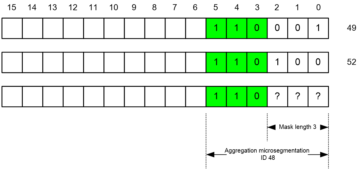
Aggregation microsegmentation is achieved by performing mask operations on the IDs of ordinary microsegments. The length of the mask determines the number of ordinary microsegments within the aggregation microsegmentation. The relationship between the ID of the aggregation microsegmentation and that of the regular microsegmentation is shown as in Figure 11. If it is desired to aggregate microsegments 49 and 52, the mask length should be configured as 3, i.e., 110XXX. Setting all the mask bits to 0 gives the ID of the aggregation microsegmentation as 48. There can be up to 2³=8 ordinary microsegments within aggregation microsegment 48, i.e., ordinary microsegments from 48 to 55.
Figure 11 Relationship between aggregation microsegmentation ID and regular microsegmentation ID
Typical applications
Typical application of EVPN VXLAN data center network
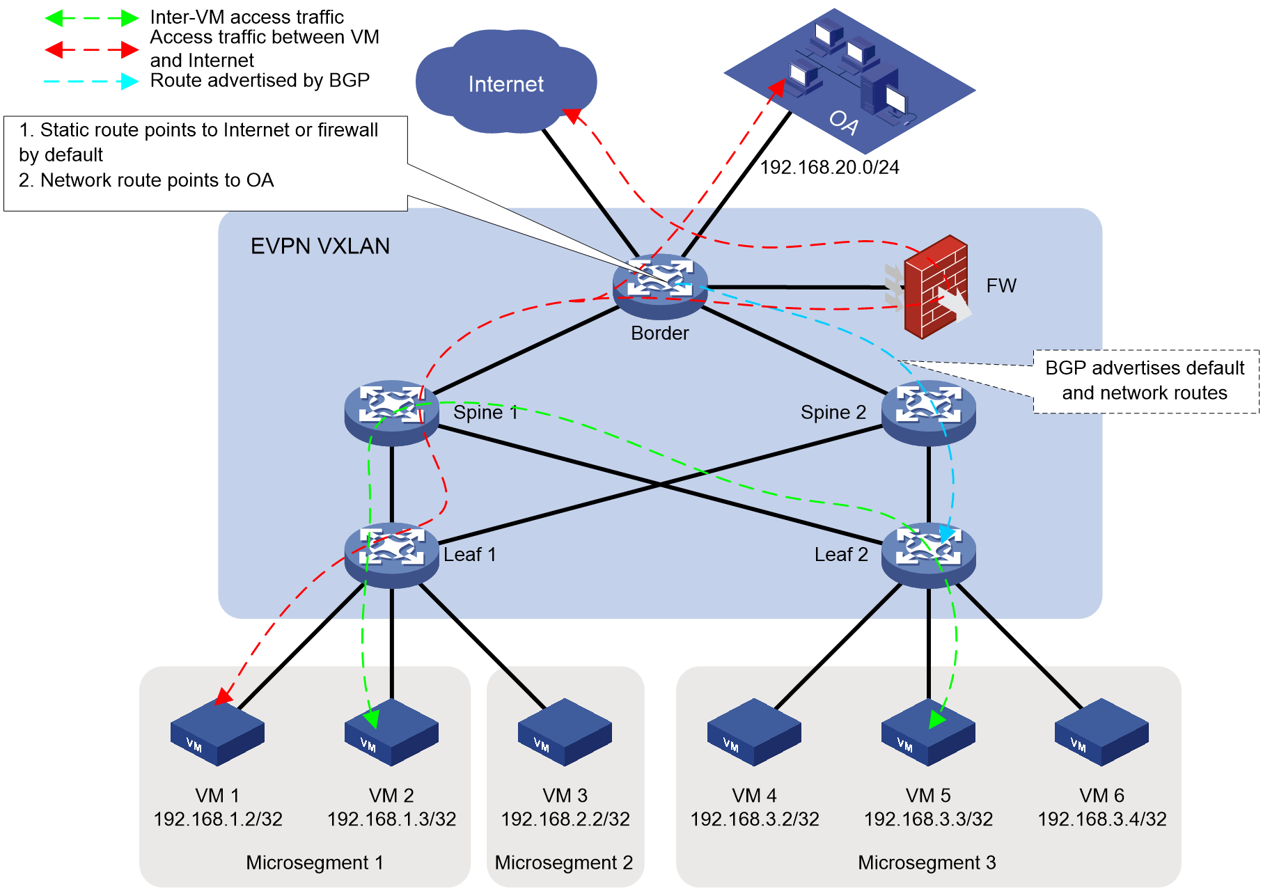
In the data center network as shown in Figure 12, microsegmentation, ACL, and GBP are deployed manually through the command or automatically by the SDN controller.
· When controlling east-west traffic, the deployment method for microsegmentation members is as follows:
Configure a unified static IP microsegmentation for VM's IP address on all Leaf sections.
Configure on both Leaf 1 and Leaf 2.
¡ The member of microsegmentation 1 is 192.168.1.0/24.
¡ The members of microsegmentation 2 are 192.168.2.0/24.
¡ The Microsegmentation 3 member is 192.168.3.0/24.
· When managing north-south traffic, the deployment method for microsegmentation members is:
On the Border, there are static default routes to the Internet and firewall, as well as network segment routes for the office automation (OA) network (i.e., 192.168.20.0/24). These routes are announced to all Leaf nodes using BGP, enabling data center communication with the outside through the Border.
To achieve north-south traffic control, it is necessary to configure a uniform static IP microsegmentation on all Leafs.
¡ Since
the Border announces the default route, microsegmentation 4 is configured on
both Leaf 1 and Leaf 2, with a member of 0.0.0.0/0.
¡ Since the Border announces the network segment route, microsegmentation 5 is configured on both Leaf 1 and Leaf 2, with a member of 192.168.20.0/24.
ACL and GBP are configured as needed, allowing OR prohibiting the traffic to pass between each microsegmentation.
Figure 12 EVPN VXLAN data center network
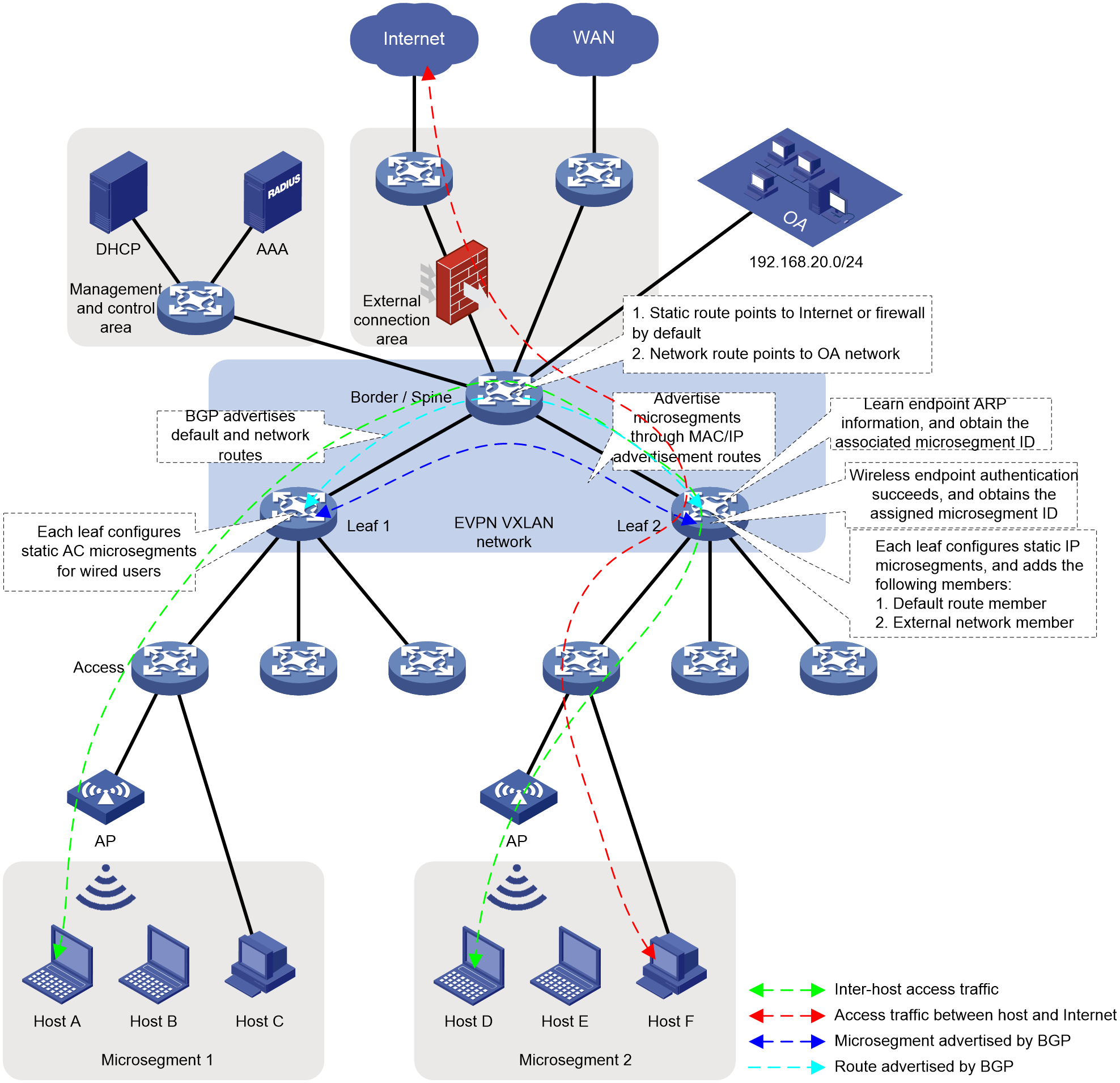
Typical application of EVPN VXLAN in campus network
In the campus network as shown in Figure 13, deploy microsegmentation manually through the command line OR automatically with an SDN controller.
· When managing east-west traffic, the deployment method for microsegmentation members is:
¡ Configure authentication authorization microsegmentation for local wired users (Host C and Host F). AAA authorizes microsegmentation ID for authenticated users, implementing the addition of wired users to specified microsegments.
AAA issues authorization information to Leaf 1, granting Host C the authorization for microsegmentation 1, thus making Host C a member of microsegmentation 1. It also issues authorization information to Leaf 2, granting Host F the authorization for microsegmentation 2, thus making Host F a member of microsegmentation 2.
¡ Configure static AC microsegmentation for local wireless users (Host A, Host B, Host D and Host E). Users access the EVPN VXLAN network via AC. By associating AC with microsegmentation on the Leaf, wired users are added to the specified microsegmentation section.
On Leaf 1, by associating Host B and Host C with the EVPN VXLAN network's AC and {microsegmentation} 1, they become members of {microsegmentation} 1. On Leaf 2, by associating Host D and Host E with the EVPN VXLAN network's AC and {microsegmentation} 2, they become members of {microsegmentation} 2.
After learning the ARP of online users, Leaf announces it to all other Leafs through BGP, carrying the corresponding microsegmentation ID during the announcement.
· When controlling traffic flow from the north-south direction, the deployment method for microsegmentation members is:
On the Border, there is a static default route to reach the Internet and the firewall, as well as a network segment route (192.168.20.0/24) for the OA network. These routes are announced to all Leaf through BGP. A unified static IP microsegmentation is configured on all Leaf across the network.
¡ Since Border announces the default route to all Leafs, microsegmentation 3 is configured on both Leaf 1 and Leaf 2, with a membership of 0.0.0.0/0.
¡ Since the Border announces the network segment route to all Leafs, microsegmentation 4 is configured on both Leaf 1 and Leaf 2, with a member of 192.168.20.0/24.
ACL (Access Control List) and GBP (Group Based Policy) are configured as needed, allowing or forbidding the traffic to pass between different microsegments.
Figure 13 EVPN VXLAN campus Network