- Released At: 17-04-2024
- Page Views:
- Downloads:
- Table of Contents
- Related Documents
-
EVPN Multicast Technology White Paper
Copyright © 2024 New H3C Technologies Co., Ltd. All rights reserved.
No part of this manual may be reproduced or transmitted in any form or by any means without prior written consent of New H3C Technologies Co., Ltd.
Except for the trademarks of New H3C Technologies Co., Ltd., any trademarks that may be mentioned in this document are the property of their respective owners.
The content in this article is general technical information, some of which may not apply to the product you purchased.
Contents
BGP EVPN neighbor establishment
Overview of BGP EVPN multicast related routes
Selective Multicast Ethernet Tag Route (RT-6)
IGMP Join Synchronization Route (RT-7)
IGMP Leave Synchronized Route (RT-8)
Multicast Flags Extended Community
EVPN multicast forwarding method
Control plane learning of Layer 2 multicast forwarding entries
Manual creation of Layer 2 multicast forwarding entries
Dynamic learning of Layer 2 multicast forwarding entries through routing
Data plane forwards Layer 2 multicast packets
Forwarding Layer 2 multicast traffic through core replication
Forwarding Layer 2 multicast traffic using head-end replication
Introduction to MDT-mode MVXLAN
Control plane establishes MDT and learns Layer 3 multicast forwarding entries
Automatic MVXLAN tunnel establishment and assignment
Learning forwarding entries for private network multicast traffic
Data plane multicast Layer 3 packet forwarding
Encapsulation of multicast packets
Layer 3 multicast traffic forwarding process
EVPN multicast supports data center interconnection
EVPN VXLAN DCI Layer 2 multicast forwarding (same L2VNI)
EVPN VXLAN DCI Layer 2 multicast forwarding (L2VNI mapping)
Layer 2 multicast DCI with dual ED support
Layer 3 Multicast Support for DCI
EVPN VXLAN DCI Layer 3 Multicast Forwarding (Same L3VNI)
EVPN VXLAN DCI Layer 3 multicast forwarding (L3VNI mapping)
Layer 3 multicast DCI with dual ED support
Overview of EVPN multicast support for DRNI mechanism
Layer 2 multicast supports DRNI
Process of route distribution and traffic forwarding under normal conditions
Layer 3 multicast supports DRNI
Process of establishing multicast VXLAN tunnels under normal conditions
Route distribution and traffic forwarding process under normal conditions
Multicast source-side fault protection
Multicast receiver-side fault protection
Urban rail multicast typical networking (source in data center, receivers at stations)
Urban rail multicast typical networking (source at station, receivers in data center)
Urban rail multicast typical networking (both station and data center have sources and receivers)
Overview
Technical background
Ethernet Virtual Private Network (EVPN) is a Layer 2 internetworking technology based on overlay technology with the advantages of simple deployment and strong expansion. It is widely used in data center networks, campus access networks, wide area networks (WAN), and carrier networks.
As the applications of IPTV, video conferencing, and distance education become increasingly widespread, users' requirements for multicast services continue to grow. EVPN networks need to support not only unicast traffic forwarding but also multicast traffic forwarding, enabling multicast sources to distribute multicast traffic to multicast receivers across the EVPN network.
EVPN uses the MP-BGP protocol to advertise multicast-related information and forwards Layer 2 and Layer 3 multicast traffic through generated multicast forwarding entries, effectively meeting user demands for multicast services. The technology that enables multicast traffic forwarding in an EVPN network is known as EVPN multicast technology.
Technical advantages
The control plane of EVPN multicast technology is implemented by BGP EVPN routing, and the data plane currently only supports VXLAN encapsulation.
The EVPN multicast technology has the following features:
· The use of BGP EVPN routing to pass private multicast protocol messages and private multicast routes between VTEPs reduces the complexity of network deployment and enhances network security, as the devices in the core network do not need to perceive these messages and routes.
· VXLAN encapsulation enables multicast service separation between the overlay network and underlay network, with neither network being aware of the other.
· It supports both Layer 2 and Layer 3 multicast traffic forwarding, offering flexible network configurations.
· The Layer 2 EVPN multicast technical supports multihoming access. One site can access the EVPN network through multiple VTEPs, enhancing the network's reliability.
· Supports DRNI, enhancing the network's reliability.
BGP EVPN multicast expansion
In the EVPN multicast technology, VTEPs use the MP-BGP protocol to advertise multicast source information and the access information of multicast receivers.
BGP EVPN neighbor establishment
BGP has added a new EVPN subaddress family for negotiating and establishing BGP EVPN neighbors. The address family number used by the EVPN subaddress family is: AFI=25, SAFI=70.
In the EVPN multicast technology, VTEPs can establish both IBGP neighbor relationships and EBGP neighbor relationships.
· When establishing IBGP neighbor relationships, to simplify the full connection configuration, it is necessary to deploy RRs. All VTEPs establish BGP neighbor relationships with only the RR. After the RR discovers and receives the BGP connection initiated by a VTEP, it forms a client list and reflects the route received from one VTEP to all other VTEPs.
· When EBGP neighbors are established, RR deployment is not necessary. BGP automatically transmits the EVPN messages received from EBGP neighbors to other EBGP and IBGP neighbors.
BGP EVPN routing
Overview of BGP EVPN multicast related routes
To support EVPN multicast, the BGP EVPN address family has added the following types of EVPN network layer reachability information (NLRI), namely EVPN routes.
· Selective Multicast Ethernet Tag Route (RT-6), also known as SMET route, is used to advertise the IGMP multicast group information of tenants.
· IGMP Join Synch Route (RT-7): This route synchronizes a tenant's IGMP join information for multicast groups among multiple members.
· IGMP Leave Synch Route (RT-8): This route advertises a tenant's IGMP leave information for multicast groups among multiple members to revoke the corresponding IGMP Join Synch Route.
· S-PMSI A-D route (RT-10): A selective multicast tunnel autodiscovery route, used to advertise multicast tunnels, triggering automatic creation of multicast tunnels.
The EVPN route in the routing process includes a Route Distinguisher (RD) field to differentiate EVPN routes of different VXLANs, preventing EVPN route conflicts.
When VTEPs send out BGP update messages with EVPN routes, they must also carry the VPN Target Extended Community attribute (also known as Route Target). The VPN Target attribute controls the distribution and reception of EVPN route information. There are two types of VPN target attributes, each of which can include multiple attribute values:
· Export target attribute: When the local VTEP transmits an EVPN route to the remote VTEP through a BGP update message, it sets the VPN target attribute carried in the update message to the export target.
· Import target attribute: When a VTEP receives an update message released by other VTEPs, it compares the VPN target attribute carried in the message with the locally configured import target attribute. Only when there is a matching attribute value in both will it receive the EVPN route in the message.
Selective Multicast Ethernet Tag Route (RT-6)
When a user connected to the VTEP wants to receive traffic from a (*,G) or (S,G) entry, they advertise this information to other VTEPs in the network through SMET (RT-6) routing. When a user no longer wants to receive this traffic, they withdraw the route.
Figure 1 SMET route format

As shown in Figure 1, the selective multicast Ethernet tag route includes the following fields:
· RD: The RD value of the EVPN instance.
· Ethernet tag ID: This field is set to all zeros.
· Multicast source length: The IP address length of the multicast source that the tenant joins, with 32 bits representing IPv4 and 128 bits representing IPv6.
· Multicast source address: The address of the multicast source that the tenant joins.
· Multicast group length: The IP address length of the multicast group that the tenant joins, where 32 represents IPv4 and 128 represents IPv6.
· Multicast group address: The group address of the multicast group that the tenant joins.
· Originator router length: The length of the IP address originating the route. 32 represents IPv4, and 128 bits represents IPv6.
· Originator router address: This is the IP address of the VTEP or PE that initiated the route, the value of which is the router ID of the BGP protocol.
· Flags: See Figure 2.
![]()
The content indicated by the flag is related to the multicast group address field.
If the multicast group address is an IPv4 address:
¡ Bit 7 indicates whether IGMP version 1 is supported.
¡ Bit 6 indicates whether IGMP version 2 is supported.
¡ Bit 5 indicates whether IGMP version 3 is supported.
¡ Bit 4 indicates the mode of the carried (S, G). The value 1 indicates the exclude mode. The value 0 indicates the include mode. This bit is only effective when the value of bit 5 is 1, and it's ignored when Bit 5 is 0.
If the multicast group address is an IPv6 address:
¡ Bit 7 indicates whether MLD version 1 is supported.
¡ Bit 6 indicates whether MLD version 2 is supported.
¡ Currently, bit 5 is fixed at 0.
¡ Bit 4 indicates the mode of the carried (S, G). The value 1 indicates the exclude mode. The value 0 indicates the include mode. This bit is only valid when bit 6 has a value of 1, and it is ignored when bit 6 value is 0.
IGMP Join Synchronization Route (RT-7)
In a multihomed network, this route is used to synchronize the IGMP join multicast group information among multiple members. After a VTEP receives a user's multicast join message (IGMP report packet) from the local site, it will transmit the IGMP join sync route to other member VTEPs.
Figure 3 IGMP Join Synchronization Route Message format
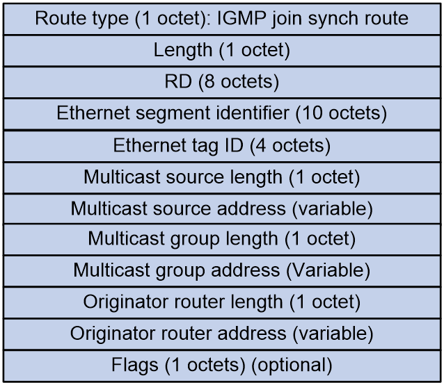
As shown in Figure 3, the IGMP join synchronization route includes the following fields:
· RD: The RD value of the EVPN instance.
· Ethernet segment identifier: The identifier (ID) of the Ethernet link section between VTEP/PE and CE.
· Ethernet tag ID: The VLAN corresponding to the access AC.
· Multicast source length: The length of the IP address of the multicast source that the tenant joins, where 32 represents IPv4 and 128 represents IPv6.
· Multicast source address: The address of the multicast source that the tenant joins.
· Multicast group length: The length of the IP address for the multicast group that the tenant joins, where 32 represents IPv4 and 128 represents IPv6.
· Multicast group address: The group address of the multicast group that the tenant joins.
· Originator router length: The length of the IP address of the router that originated the route: 32 represents IPv4, and 128 represents IPv6.
· Originator router address: The IP address of the originating VTEP or PE of this route, which is determined by the router ID of the BGP protocol.
· Flags: The defined flags are shown in Figure 4.
![]()
The content indicated by the flag bit is related to the multicast group address field.
If the multicast group address is an IPv4 address:
¡ Bit 7 indicates whether IGMP version 1 is supported.
¡ Bit 6 indicates if IGMP version 2 is supported.
¡ Bit 5 indicates whether IGMP version 3 is supported.
¡ Bit 4 indicates the (S,G) mode. The value 1 indicates the exclude mode. The value 0 indicates the include mode. This bit is only effective when bit 5 has a value of 1. If bit 5 is 0, this bit is ignored.
If the multicast group address is an IPv6 address:
¡ Bit 7 indicates whether MLD version 1 is supported.
¡ Bit 6 indicates whether MLD version 2 is supported.
¡ Currently, the fixed value of bit 5 is set to 0.
¡ Bit 4 indicates the (S, G) mode. The value 1 indicates the exclude mode. The value 0 indicates the include mode. This bit is only effective when bit 6 is 1, and it is ignored when bit 6 is 0.
IGMP Leave Synchronized Route (RT-8)
In a multihomed network, the IGMP Leave Synchronization route (RT-8) is used to synchronize the IGMP leave multicast group information among multihomed members in order to withdraw the corresponding IGMP Join Synchronization route. After receiving the user's multicast leave information (IGMP leave message) from the local site, the VTEP will send the IGMP Leave Synchronization route to other multihomed member VTEPs.
Figure 5 IGMP leave synch route message format

As shown in Figure 5, the IGMP leave synchronization route includes the following fields:
· RD: The RD value of the EVPN instance.
· Ethernet segment identifier: The identifier (ID) of the Ethernet link segment between VTEP/PE and CE.
· Ethernet Tag ID: The VLAN corresponding to the access AC.
· Multicast source length: It refers to the length of the IP address of the multicast source that the tenant joins. 32-bit represents IPv4, and 128-bit represents IPv6.
· Multicast source address: The address of the multicast source that the tenant joins.
· Multicast group length: The length of the IP address for the multicast group that the tenant joins; 32 represents IPv4, and 128 bits represent IPv6.
· Multicast group address: The group address of the multicast group that the tenant joins.
· Originator router length: The length of the IP address from the originating router. 32 represents IPv4 and 128 represents IPv6.
· Originator router address: The originating IP address of the VTEP or PE for this route, with a value equal to the router ID of the BGP protocol.
· Leave group synchronization: Sequence number when a tenant leaves the multicast group.
· Max response time: This refers to the maximum response time advertised.
· Flags: The currently defined flags are shown in Figure 6.
![]()
The content indicated by the flag bit is related to the multicast group address field.
If the multicast group address is an IPv4 address:
¡ Bit 7 indicates whether IGMP version 1 is supported.
¡ Bit 6 indicates if IGMP version 2 is supported.
¡ Bit 5 indicates whether IGMP version 3 is supported.
¡ Bit 4 represents the mode of the carried (S,G). The value 1 indicates the exclude mode. The value 0 indicates the include mode. This bit is only valid when bit 5 has a value of 1, and it is ignored when bit 5 has a value of 0.
If the multicast group address is an IPv6 address:
¡ Bit 7 indicates whether MLD version 1 is supported.
¡ Bit 6 indicates whether MLD version 2 is supported.
¡ Currently, the fixed value of bit 5 is set to 0.
¡ The bit 4 indicates the mode of the carried (S,G). The value 1 indicates the exclude mode. The value 0 indicates the include mode. This bit is only effective when the value of bit 6 is 1 and is ignored when the value of bit 6 is 0.
S-PMSI A-D route
This route is used to advertise multicast tunnels and trigger their automatic establishment. When the multicast source-side VTEP meets the tunnel switchover condition and needs to create a data MDT, it transmits an S-PMSI A-D Route to notify other VTEPs to switch over the tunnel.
Figure 7 The message format of selective multicast tunnel autodiscovery route.

As shown in Figure 7, the Selective Multicast Tunnel Autodiscovery Route includes the following fields:
· RD: The RD value of the EVPN instance.
· Ethernet tag ID: This field is set to all 0s.
· Multicast source length: The length of the IP address of the multicast source that the tenant joins: a length of 32 bits represents IPv4, while a length of 128 bits represents IPv6.
· Multicast source address: The address of the multicast source that the tenant joins.
· Multicast group length: The IP address length of the multicast group that the tenant joins, where 32 represents IPv4 and 128 represents IPv6.
· Multicast group address: The group address of the multicast group that the tenant joins.
· Originator router length: The length of the IP address of the router that originated the route; 32 represents IPv4, and 128 bits represent IPv6.
· Originator router address: The IP address of the VTEP or PE originating the route, with the value being the router ID of the BGP protocol.
When both the multicast source address and multicast group address fields have a value of all 0s, this route is known as a Wildcard S-PMSI A-D Route. The Wildcard S-PMSI A-D Route are used to advertise the default MDT in an MVXLAN network.
BGP EVPN route attributes
PMSI Tunnel
The Provider Multicast Service Interface (PMSI) is a logical channel that aan underlay network uses to carry overlay network multicast traffic. The source-side VTEP distributes the overlay multicast data traffic to other VTEPs through the PMSI. The recipient VTEPs receive the multicast traffic belonging to the same VPN based on the PMSI. The MVXLAN tunnel (multicast VXLAN tunnel) on the public network is a concrete implementation form of the PMSI.
The PMSI Tunnel attribute is primarily used for creating public network MVXLAN tunnels. It is currently carried in the S-PMSI A-D route, as shown in the format depicted in Figure 8.
Figure 8 PMSI Tunnel attribute format
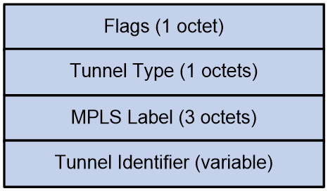
The meanings of each field in the PMSI Tunnel attribute are as follows:
· Flags: Flag bit. The value is fixed at 0, which indicates that the receiver-side VTEP does not need to respond after receiving the S-PMSI A-D route message.
· Tunnel Type: Only two types of tunnels are supported: PIM SM tunnel (4) and PIM SSM tunnel (3).
· MPLS Label: This field is not supported in the current software version.
· Tunnel Identifier: Tunnel Information. The tunnel information for both PIM SM and PIM SSM Tunnels is <Sender Address, P-Multicast Group>.
Multicast Flags Extended Community
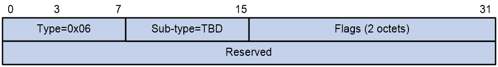
The VTEP device advertises its support for IGMP proxy capability through the Multicast Flags Extended Community. It is carried in the Inclusive Multicast Ethernet Tag Route, with the format as shown in Figure 9. The Flags value is 1, which indicates that the VTEP supports IGMP proxy.
Figure 9 Multicast Flags Extended Community format
EVPN multicast forwarding method
In the EVPN network, multicast traffic forwarding includes the following two methods:
· Layer 2 multicast: The multicast source and the multicast receiver are located in the same VXLAN network. The multicast traffic is forwarded within the same VXLAN network according to Layer 2 multicast forwarding entries (such as IGMP snooping and PIM snooping entries).
· Layer 3 multicast: The multicast source and receiver are located in different VXLAN networks but in the same VPN. Multicast traffic spans VXLAN networks within the same VPN and is forwarded based on Layer 3 multicast forwarding entries (such as IGMP and PIM entries).
EVPN VXLAN Layer 2 multicast
Control plane learning of Layer 2 multicast forwarding entries
The device can establish Layer 2 multicast forwarding entries in the following two ways:
· Manually create a Layer 2 multicast VXLAN tunnel via the command line, thereby establishing an entry in the Layer 2 multicast forwarding table.
· Learn the Layer 2 multicast forwarding entries dynamically through IGMP messages and BGP EVPN routes.
In the EVPN VXLAN Layer 2 multicast network, the priority of a Layer 2 multicast forwarding entry manually created via a command line is higher than that of a Layer 2 multicast forwarding entry learned dynamically through routing.
Manual creation of Layer 2 multicast forwarding entries
After you specify the same VXLAN flooding multicast address on all VTEPs within the same VXLAN network, all the VTEPs will join the same multicast group. The core network device then uses a multicast routing protocol (such as PIM) to establish a multicast forwarding entry for that multicast group on the IP core network, thus setting up a Layer 2 multicast VXLAN tunnel between VTEPs. At the same time, a Layer 2 multicast forwarding entry will be established on the VTEP, with the egress interface as the Layer 2 multicast VXLAN tunnel interface. The VTEP serves as both the multicast source and the multicast receiver. The multicast traffic transmitted by the VTEP is sent to all other VTEPs within the same VXLAN network through the Layer 2 multicast VXLAN tunnel.
Dynamic learning of Layer 2 multicast forwarding entries through routing
Overview
When a VTEP receives IGMP report and leave messages, it determines the VSI to which the messages belong and creates or deletes Layer 2 multicast forwarding entries within that VSI. The VTEP advertises multicast group information to other VTEPs via SMET routes. Upon receiving the SMET route, remote VTEPs determine the VSI to which the route belongs based on the Route Target and create or delete Layer 2 multicast forwarding entries within that VSI. The output port for the entry is the VXLAN unicast tunnel interface connecting the VTEP that sent the SMET route. If multiple VTEPs send SMET routes, multiple VXLAN unicast tunnel output ports will be added, each connecting to a different VTEP that sends the SMET route. When a VTEP receives another report message belonging to the same IGMP version and joining the same multicast group, it will not send SMET routes again. This mechanism greatly reduces the number of IGMP message flooding occurrences.
To support multicast, MP-BGP has added three types of EVPN routes: SMET, IGMP-JS, and IGMP-LS. For more information, see BGP EVPN routing.
Dynamic learning of Layer 2 multicast forwarding entries in single-homed site networking
As shown in Figure 10, within a single-homed site network, Receiver 1 transmits an IGMP membership report message to VTEP 1. VTEP 1 creates a corresponding Layer 2 multicast forwarding entry and transmits SMET route, announcing multicast information to VTEP 2 and VTEP 3. Upon receiving SMET route, VTEP 2 and VTEP 3 locally establish a Layer 2 multicast forwarding entry with the egress interface as the VXLAN tunnel interface (which connects to VTEP 1).
Figure 10 Single-homed site multicast

After Receiver 1 transmits an IGMP leave message to VTEP 1, VTEP 1 deletes the corresponding entry in the Layer 2 multicast forwarding table and withdraws the SMET route. Upon receiving the SMET route withdrawal, VTEP 2 and VTEP 3 delete the corresponding entry in the Layer 2 multicast forwarding table.
Dynamic learning of Layer 2 multicast forwarding entries in multihomed site networking
When a site connects to multiple VTEPs through different Ethernet links, these links form an Ethernet Segment (ES), identified by the same ES Identifier (ESI) to indicate that they belong to the same ES. The connected VTEPs form a redundancy group, which can prevent a single point of failure of the VTEP from affecting the network, thereby improving the reliability of the EVPN VXLAN network.
To prevent all VTEPs in the redundancy group frm transmitting multicast traffic to the site, a Designated Forwarder (DF) needs to be elected among VTEPs for each AC in the redundancy group, responsible for forwarding multicast traffic to that AC. Other VTEPs serve as the backup DFs (BDFs) for the AC and will not forward multicast traffic to the local site.
In a site multi-homing network, join messages and leave messages transmitted by the site are received by different VTEPs. To manage Layer 2 multicast forwarding entries among multi-homing sites, the VTEP that receives the join messages and leave messages will transmit IGMP-JS routes and IGMP-LS routes to inform other members, ensuring the synchronization of multicast information among ESI member VTEPs.
Figure 11 Multihomed site multicast
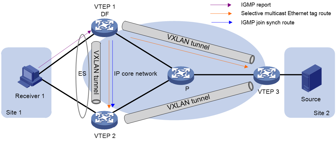
As shown in Figure 11, the learning process for Layer 2 multicast entries in multihomed sites is as follows:
· When the device receiving the report message is the DF (VTEP 1), the DF establishes the corresponding Layer 2 multicast forwarding entry, advertises an SMET route to VTEP 2 and VTEP 3, and advertises an IGMP-JS route to VTEP 2. VTEP 2 and VTEP 3 locally establish a Layer 2 multicast forwarding entry, where the egress interfaces are the interface where ES is located and the VXLAN tunnel interface connecting to VTEP 1, respectively.
When the multicast receiver leaves the multicast group:
¡ If the DF receives the leave message, it deletes the Layer 2 multicast forwarding entry, advertises the IGMP-LS route, and withdraws the IGMP-JS and SMET routes. Upon receiving these routes, VTEP 2 and VTEP 3 delete their corresponding Layer 2 multicast forwarding entries.
¡ If the BDF (VTEP 2) receives the leave message, it advertises the IGMP-LS route to other members in the same redundancy group. The DF, upon receiving the IGMP-LS route from the BDF, withdraws the IGMP-JS and SMET routes. All VTEPs then delete their corresponding Layer 2 multicast forwarding entries.
· When the device receiving the report message is the BDF (VTEP 2), the BDF establishes the corresponding Layer 2 multicast forwarding entry and advertises the IGMP-JS route to other members in the same redundancy. Upon receiving the IGMP-JS route, the DF (VTEP 1) establishes the corresponding Layer 2 multicast forwarding entry, with the egress interface being the interface where ES is located. The DF generates an SMET route and advertises it to VTEP 2 and VTEP 3. VTEP 3 locally establishes a Layer 2 multicast forwarding entry, with the egress interface being the VXLAN tunnel interface connecting to VTEP 1.
When the multicast receiver leaves the multicast group:
¡ If the DF receives the leave message, it deletes the Layer 2 multicast forwarding entry and advertises the IGMP-LS route to others in the redundancy group. The BDF, upon receiving the IGMP-LS route, deletes its Layer 2 multicast forwarding entry and withdraws the IGMP-JS route. The DF, after receiving the withdrawn IGMP-JS route, revokes the SMET route generated by it. VTEP 3, upon receiving the revoked SMET route, deletes the corresponding Layer 2 multicast forwarding entry.
¡ If the BDF receives the leave message, it deletes the Layer 2 multicast forwarding entry, advertises the IGMP-LS route, and withdraws the IGMP-JS route. The DF, upon receiving the withdrawn IGMP-JS route, deletes its Layer 2 multicast forwarding entry and revokes the SMET route generated by that IGMP-JS route. VTEP 3, after receiving the revoked SMET route, deletes the corresponding Layer 2 multicast forwarding entry.
Data plane forwards Layer 2 multicast packets
Forwarding Layer 2 multicast traffic through core replication
After Layer 2 multicast forwarding entries are learned, when the VTEP receives a Layer 2 multicast data frame, it determines its belonging VSI and looks up the Layer 2 multicast forwarding entry of the VSI according to the destination MAC address or the destination IP. The data frame is forwarded through the egress interface of the entry. If the egress interface is a local interface, the VTEP directly forwards the data frame through this interface. If the egress interface is a Layer 2 multicast VXLAN tunnel interface, the VTEP adds a VXLAN encapsulation to the data frame (with the destination address set to the VXLAN flooding multicast address configured on the VTEP), and then it passes the encapsulated frame to the remote VTEP through the Layer 2 multicast VXLAN tunnel.
Figure 12 Layer 2 multicast traffic forwarding using core replication method
Forwarding Layer 2 multicast traffic using head-end replication
After Layer 2 multicast forwarding entries are learned, when the VTEP receives a Layer 2 multicast data frame, it determines its belonging VSI. Based on the destination MAC address or IP address, it looks up the Layer 2 multicast forwarding table of the VSI and forwards the data frame through the egress interface of the entry. If the egress interface is a local interface, the VTEP directly forwards the data frame through this interface. If the egress interface is a VXLAN tunnel interface, the VTEP adds a VXLAN encapsulation to the data frame based on the VXLAN tunnel interface and forwards it to the remote VTEP through the VXLAN tunnel.
When multiple VXLAN tunnel interfaces exist in the Layer 2 multicast forwarding entry (indicating that multiple remote VTEPs are connected to the multicast receiver), the VTEP will add the corresponding VXLAN encapsulation for each data frame of each VXLAN tunnel interface, and pass them through multiple VXLAN tunnels to multiple remote VTEPs.
Figure 13 Head-end replication method for forwarding Layer 2 multicast traffic

EVPN VXLAN Layer 3 multicast
Introduction to MDT-mode MVXLAN
EVPN multicast uses the Multicast Distribution Tree (MDT) mode to forward Layer 3 multicast traffic. The MDT mode establishes a distribution tree with the VTEP, where the multicast source resides, as the root and the VTEP, where the multicast receiver is located, as the leaf on the public network. The multicast traffic is forwarded along the distribution tree in the public network through a one-way MVXLAN tunnel, thus achieving optimal path forwarding for multicast traffic.
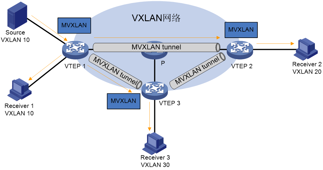
As shown in Figure 14, all VTEPs are distributed EVPN gateways, and MVXLAN tunnels are set up between VTEPs. The creation of MVXLAN instances on the VTEP guides multicast traffic forwarding, which passes the multicast traffic to local receivers and remote VTEPs through the local AC and MVXLAN tunnel, respectively.
Control plane establishes MDT and learns Layer 3 multicast forwarding entries
Concepts
· MVXLAN network: It is a multicast traffic forwarding network composed of the same or different VXLAN networks that belong to the same VPN.
· MVXLAN instance: The instantiation of the MVXLAN network on a VTEP. An MVXLAN instance is associated with a VPN instance to save the multicast configuration and multicast forwarding entries related to the VXLAN within the VPN, achieving isolation of multicast services in different private networks.
· MDT: An MDT is a multicast distribution tree constructed by all VTEPs in the same MVXLAN. MDTs include the default MDT and the data MDT.
· Default group: A default group is a unique multicast address assigned to each MVXLAN on the public network. It is the unique identifier of an MVXLAN on the public network and helps build the default MDT for an MVXLAN on the public network. Packets of the private multicast groups in an MVXLAN are encapsulated into packets of the default group before they are transmitted on the public network.
· Default MDT: A default MDT uses a default group address as its group address. The default MDT of an MVXLAN is uniquely identified by the default group and transmits all private multicast packets of the MVXLAN. A default MDT is automatically created after the default group is specified and will always exist on the public network, regardless of whether multicast services exist on the public network or MVXLAN.
· Data group: An MVXLAN is assigned a unique data group for MDT switchover. If you use an ACL to match the multicast traffic of an MVXLAN, the ingress VTEP selects a least used address from the data group range to encapsulate the matching multicast packets of the MVXLAN. Other VTEPs are notified to use the address to forward the matching traffic of the MVXLAN. This initiates the switchover to the data MDT
· Data MDT: A data MDT is an MDT that uses a data group as a group address and is used to carry multicast services from one or multiple multicast groups. There might be multiple default-MDTs within an MVXLAN network. At MDT switchover, VTEPs with downstream receivers join a data group to build a data MDT. The ingress VTEP forwards the encapsulated MVXLAN multicast traffic along the data MDT over the public network.
MP-BGP extension
To support MVXLAN, MP-BGP introduces the following routes for creating MDTs under the EVPN address family:
· Supplementary broadcast domain selective multicast Ethernet tag (SBD-SMET) route—Contains private multicast source address and private multicast group address information. A receiver-side VTEP uses the SBD-SMET route to advertise its interest in a specific (*, G) or (S, G). An SBD-SMET route carries the RD configured in VPN instance view and export targets configured in VPN instance IPv4 or IPv6 address family view.
· Selective provider multicast service interface route—Also known as S-PMSI A-D route. An S-PMSI A-D route contains the private multicast source address, private multicast group address, default or data group address, and MVXLAN source interface address. S-PMSI A-D routes are used by the multicast source-side VTEP and its BGP peers to establish the default MDT and switch traffic from the default MDT to a data MDT. An S-PMSI A-D route carries the RD configured in VPN instance view and export targets configured in VPN instance IPv4 or IPv6 address family view.
For more information about EVPN route, see BGP EVPN routing.
Automatic MVXLAN tunnel establishment and assignment
In an MVXLAN network, VTEPs automatically establish MVXLAN tunnels and assign them to MVXLANs to forward Layer 3 multicast traffic. The tunnel source is the MVXLAN source interface address, and the tunnel destination is the default or data group address. An MVXLAN tunnel is a unidirectional tunnel from the multicast source-side VTEP to a multicast receiver-side VTEP.
Default MDT establishment
The default MDT is a multicast distribution tree established among all VTEPs within the same MVXLAN network. All the multicast protocols and packets exchanged between different VTEPs are forwarded through the multicast VXLAN tunnel formed by this distribution tree.
EVPN MVXLAN relies on S-PMSI A-D routes to automatically establish a default MDT (multicast VXLAN tunnel). The S-PMSI A-D route carries (*, *) information to identify all private network multicast traffic.
Figure 15 Default MDT establishment in a PIM-SM network
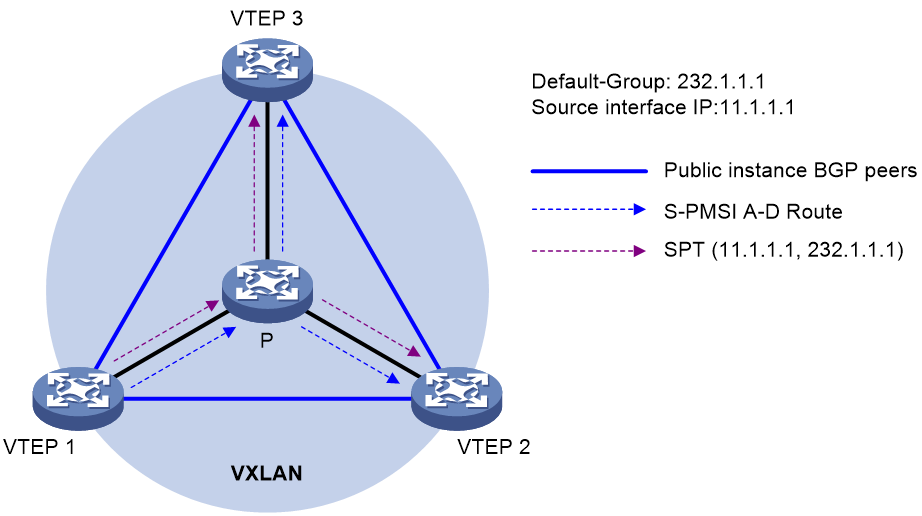
The multicast routing protocol running in the public network can be either PIM-SM or PIM-SSM. In both cases, the establishment process for the default MDT is the same. As shown in Figure 15, the process for establishing a default MDT when PIM-SM is running in the public network is as follows:
1. VTEP 1 sends an S-PMSI A-D route that contains (*, *) to VTEP 2 and VTEP 3. The S-PMSI A-D route's PMSI Tunnel Attribute carries multicast VXLAN tunnel information, including the public network multicast source address (the IP address of the MVXLAN tunnel source interface on VTEP 1), the public network multicast group address (default group configured on VTEP 1), and L3VNI (Layer 3 VXLAN ID).
2. After receiving the S-PMSI A-D route, if the export target carried by this route matches the import target of a local VPN instance, VTEP 2 and VTEP 3 will establish a multicast VXLAN tunnel with VTEP 1. The establishment process is as follows:
a. VTEP 2 and VTEP 3 transmit PIM join messages to VTEP 1 to join (S, G) (where S and G respectively represent the multicast source address and group address on the public network carried by the PMSI Tunnel Attribute). They establish multicast forwarding entries along the public network. This forms a shortest path tree (SPT) with VTEP 1 as the root and VTEP 2 and 3 as the leaves. This SPT is the default MDT.
b. VTEP 2 and VTEP 3 will establish a multicast VXLAN tunnel associated with L3VNI. This tunnel is used for encapsulating layer 3 multicast traffic.
3. VTEP 2 and VTEP 3 also initiate a similar process to establish the default MDT, ultimately forming three independent SPT trees in the underlay network, each connecting a VTEP with other VTEPs.
MDT switchover
Introduction to MDT switchover
When a multicast packet of a VPN is transmitted through the default MDT on the public network, the packet is forwarded to all PEs that support that VPN instance. This occurs whether or not any active receivers exist in the attached sites. When the rate of the multicast traffic of that VPN is high, multicast data might get flooded on the public network. This increases the bandwidth use and brings extra burden on the PEs.
data MDT can be used to solve the mentioned problems: Set specific rules (currently, only ACL rules are supported) on the multicast source side VTEP. When the VTEP detects that the multicast data meets these rules, it will create a new data MDT. Only VTEPs that are interested in this multicast data will join this data MDT. The multicast traffic is then forwarded along the data MDT to the VTEPs that truly have a receive requirement.
data MDT switchover relies on S-PMSI A-D routes. When VTEP initiates a data MDT switchover, the multicast source-side VTEP sends an S-PMSI A-D class route, with the Multicast Source Address and Multicast Group address corresponding to the customer site traffic's (S, G). At the same time, the PMSI Tunnel Attribute in the route carries information about the public network multicast VXLAN tunnel, including the public network multicast source address (IP address of the MVXLAN tunnel source interface on multicast source-side VTEP), public network multicast group address (Data-group address), and L3VNI. VTEPs wishing to receive this multicast data will send a PIM join message after receiving the route to join the data MDT. VTEPs without connected receivers will not join the data MDT after receiving the route, but will cache the message for quick joining of data MDT once receivers become available.
Switching from default MDT to data MDT
The process of switching from default MDT to data MDT is as follows:
1. Private multicast traffic passes the ACL rule filtering for default MDT to data MDT switchover.
2. The source-side VTEP selects a least-used address from the data group range and sends an S-PMSI A-D route to all the other VTEPs down the default MDT. This route contains the private multicast source address, private multicast group address, IP address of the MVXLAN source interface, and data group address.
3. Each VTEP that receives the route examines whether it has receivers of that private multicast stream.
If so, it joins the data MDT rooted at the source-side VTEP. Otherwise, it caches the route and will join the data MDT when it has attached receivers.
4. After sending the S-PMSI A-D route, the source-side VTEP starts the data-delay timer. When the timer expires, the source-side VTEP uses the data group address to encapsulate the private multicast traffic. The multicast traffic is then forwarded down the data MDT. The data-delay timer
5. After the multicast traffic is switched from the default MDT to the data MDT, a downstream VTEP can leave the data MDT by sending a PIM prune message if it no longer has active receivers attached to it.
Switching from the data MDT to the default MDT
After the MXVLAN multicast traffic is switched to the data MDT, the multicast traffic conditions might change and no longer meet the switchover criterion. In this case, the source-side VTEP initiates a backward MDT switchover process when any of the following criteria are met:
· The associated data group range is changed, and the data group address for encapsulating the MVXLAN multicast traffic is not in the new address range.
· The ACL rule for controlling the switchover from the default MDT to the data MDT has changed, and the MVXLAN multicast traffic fails to pass the new ACL rule.
Learning forwarding entries for private network multicast traffic
In EVPN VXLAN Layer 3 multicast group networking, the VTEP dynamically learns Layer 3 multicast forwarding entries for private network multicast traffic through IGMP messages and BGP EVPN routes.

The process of learning private network multicast layer 3 forwarding entry, triggered by different multicast receivers, is similar. As shown in Figure 16, taking Receiver 2 as an example, the learning process of the layer 3 multicast forwarding entry for private network multicast traffic is as follows:
1. Receiver 2, the multicast receiver, transmits an IGMP membership report message (hereinafter referred to as IGMP Report message), requesting to join the multicast group (*, G).
2. After VTEP 2 receives the IGMP report, it generates a Layer 3 multicast forwarding entry, with the port leading to the connection of the Receiver's AC.
3. VTEP 2 transmits the SMET route carrying the (*,G) information to VTEP 1 and VTEP 3.
4. After receiving the SMET route, VTEP 1 and VTEP 3 generate Layer 3 multicast forwarding entries with the multicast VXLAN tunnel (default MDT or data MDT) as the egress interface.
Data plane multicast Layer 3 packet forwarding
Layer 3 multicast currently only supports core-based replication and does not yet support head-end replication.
Encapsulation of multicast packets
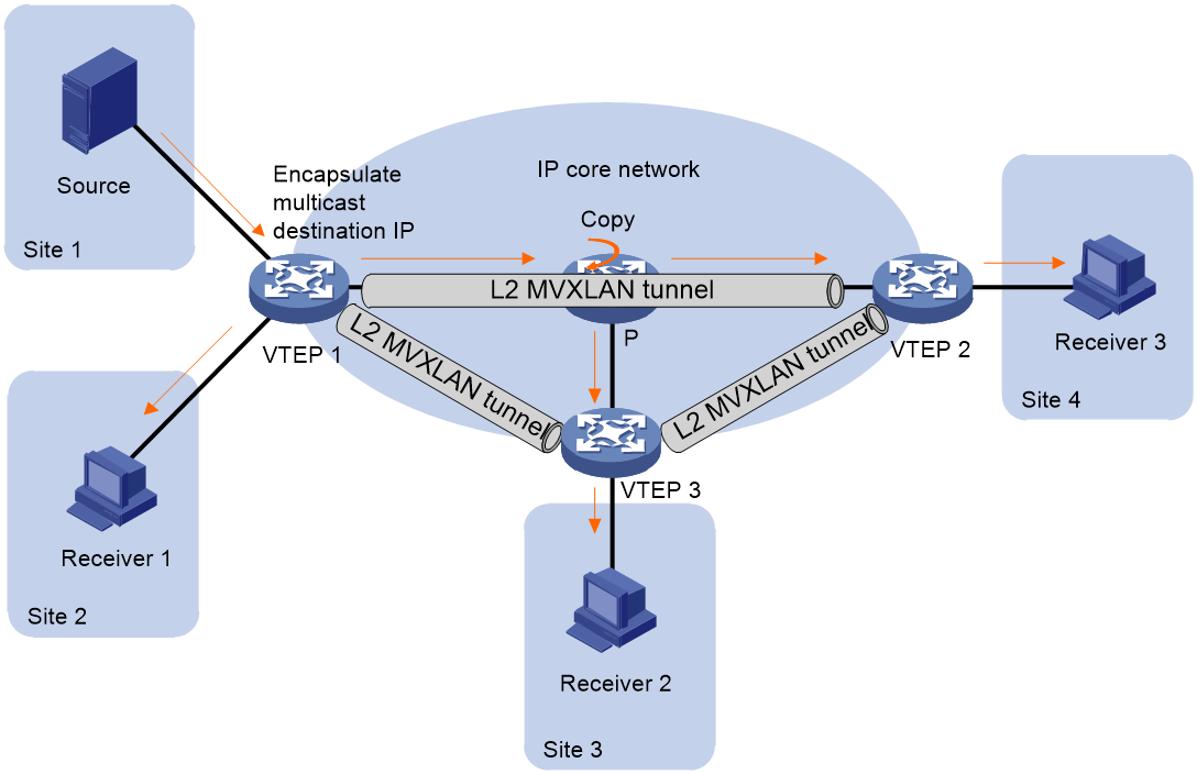
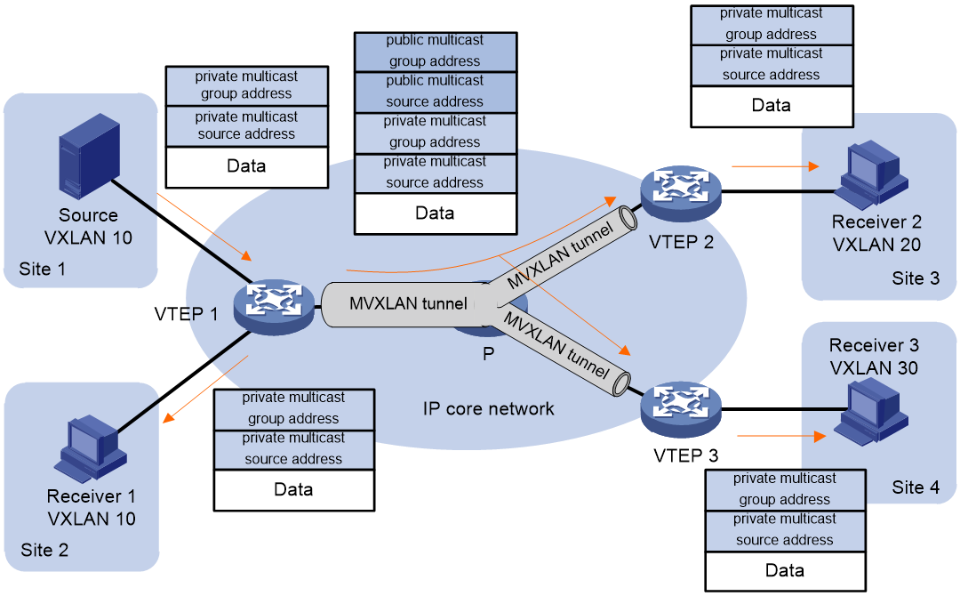
Before the VTEP forwards the multicast packet (known as the private network multicast packet) sent by the multicast source within the local site network to the remote VTEP, it adds a VXLAN encapsulation. The destination address of the encapsulation is the public network multicast group address, that is, the VTEP transforms the private network multicast packet into a public network multicast packet. Based on the public network multicast group address, the multicast packet is forwarded on the public network, thus achieving the transparency of the private network multicast traffic on the public network. The public network multicast group address could be the Default-Group address OR the Data-Group address.
Figure 17 Diagram showing the encapsulation of multicast packets
Layer 3 multicast traffic forwarding process
In a distributed EVPN gateway scenario, for both Layer 2 and Layer 3 multicast traffic, forwarding is performed by looking up the Layer 3 multicast forwarding entry.
Figure 18 Diagram of Layer 3 multicast traffic forwarding process

As shown in Figure 18, the forwarding process for Layer 3 multicast traffic is as follows:
1. After receiving a multicast packet, the VTEP identifies the associated VSI and searches for the VSI virtual interface. It then looks for Layer 3 multicast forwarding entries within the VPN instance linked to the VSI virtual interface and forwards the packet based on the matched forwarding entry:
¡ If the egress interface of the Layer 3 multicast forwarding entry is a local interface, the VTEP forwards the multicast traffic to the multicast receiver through the local interface.
¡ If the egress interface of the layer 3 multicast forwarding entry is the multicast VXLAN tunnel interface, then the VTEP adds the VXLAN encapsulation of the multicast VXLAN tunnel (source address is the IP address of MVXLAN tunnel source interface, destination address is Default-group OR Data-group address) before forwarding it to the Underlay network. In this context, the VXLAN ID used for packet encapsulation is the L3VNI associated with the VPN-instance.
2. Devices in the underlay network send multicast packets to remote VTEPs based on established public network Layer 3 multicast forwarding entries.
3. After the remote VTEP receives a packet, it determines the VPN-instance that the packet belongs to based on the L3VNI, and performs decapsulation on the VXLAN. Then, it finds the entry of the Layer 3 multicast forwarding table within that VPN-instance. If there are local multicast recipients, the decapsulated multicast packet is forwarded to them. If no local multicast recipients exist, the packet is discarded.
EVPN multicast supports data center interconnection
Layer 2 multicast enables DCI
EVPN VXLAN DCI Layer 2 multicast forwarding (same L2VNI)
Data centers use Edge Devices (EDs) at their periphery. EDs establish VXLAN-DCI tunnels using VXLAN encapsulation. VXLAN tunnels are created within the data center. The same L2VNI is utilized by a tenant across all data centers. Traffic across data centers reaches an ED through a VXLAN tunnel and is then forwarded to other data center EDs via the VXLAN-DCI tunnel. When Layer 2 traffic is sent between EDs through the VXLAN-DCI tunnel, it carries the L2VNI.
Figure 19 EVPN VXLAN DCI Layer 2 Multicast Forwarding (With Same L2VNI)

In the network setup depicted in Figure 19, the route release process is as follows:
1. The receiver sends an IGMP report message, requesting to join the multicast group (*, G).
2. After VTEP 2 detects the IGMP report message through IGMP Snooping, it generates a Layer 2 multicast forwarding entry with the output port connected to the Receiver's AC.
3. VTEP 2 transmits SMET route carrying (*, G) information to ED 2.
4. Upon receiving the SMET route, ED 2 generates a Layer 2 multicast forwarding entry, with the output port being a unicast VXLAN tunnel pointing to VTEP 2 (in head-end replication mode) OR a Layer 2 multicast VXLAN tunnel (in core replication mode).
5. After changing the next hop of the route to its own IP address, ED 2 continues to forward the SMET route to ED 1.
6. After receiving the SMET route, ED 1 generates a Layer 2 multicast forwarding entry. The egress port is the unicast VXLAN-DCI tunnel pointing towards ED 2.
7. ED 1 changes the route's next hop to its own IP address and continues to forward the SMET route to VTEP 1.
8. Upon receiving the SMET route, VTEP 1 will generate a Layer 2 multicast forwarding entry. The output port will direct to the unicast VXLAN tunnel towards ED 1 (under head-end replication) OR to the Layer 2 multicast VXLAN tunnel (under core replication).
In the network setup shown in Figure 19, the message forwarding process is as follows:
1. Upon receiving the multicast datagram sent by the multicast source (Source) at VTEP 1, the datagram is forwarded to ED 1 through unicast VXLAN tunnel (in head-end replication mode) or Layer 2 multicast VXLAN tunnel (in core replication mode).
2. After ED 1 removes the VXLAN encapsulation, it re-encapsulates the packets using VXLAN. Then, it transmits the packets to ED 2 through the VXLAN-DCI tunnel.
3. After ED 2 removes the VXLAN encapsulation, it re-encapsulates the message and forwards it to VTEP 2 either through a unicast VXLAN tunnel (in a header copy mode) or a Layer 2 multicast VXLAN tunnel (in a core copy mode).
4. After VTEP 2 removes the VXLAN encapsulation, it transmits the packet to the multicast receiver.
EVPN VXLAN DCI Layer 2 multicast forwarding (L2VNI mapping)
In the scenario of data center interconnection, if the same tenant uses different L2VNI within each data center, but still needs to implement Layer 2 multicast intercommunication across data centers, this issue of differing L2VNI can be resolved through L2VNI mapping.
The L2VNI mapping includes:
· Map the local VXLAN directly to another VXLAN used in a different data center. In this method, you only need to specify the remote VXLAN mapping on the ED of one data center.
· Map the local VXLAN on the ED of different data centers to the same VXLAN (called the intermediate VXLAN). When using this method, it is necessary to specify the mapping of the remote VXLAN to the intermediate VXLAN on the ED of all data centers.
Figure 20 Schematic Diagram of EVPN VXLAN DCI Layer 2 Multicast Forwarding (L2VNI Mapping)

In the network configuration shown in Figure 20, take the mapping of middle VXLAN 1000 as an example, the process of route release is as follows:
1. The Receiver transmits an IGMP report message, requesting to join the multicast group (*, G).
2. After VTEP 2 listens to the IGMP report message via IGMP Snooping, it generates a multicast forwarding entry at Layer 2, where the output port connects to the receiver's AC.
3. VTEP 2 transmits the SMET route carrying (*,G) information to ED 2.
4. Upon receiving the SMET route, ED 2 generates a Layer 2 multicast forwarding entry, with the outbound port being either a unicast VXLAN tunnel pointing to VTEP 2 (in head-end replication mode) OR a Layer 2 multicast VXLAN tunnel (in core replication mode).
5. ED 2 modifies the RT of the SMET route to the RT of the middle VXLAN, and continues to forward the SMET route to ED 1.
6. After receiving the SMET route, ED 1 generates a Layer 2 multicast forwarding entry, with the egress port being the unicast VXLAN-DCI tunnel leading to ED 2.
7. ED 1 modifies the RT of the route to the RT of VXLAN within DC 1, and continues to forward the SMET route to VTEP 1.
8. Upon receiving the route, VTEP 1 creates a Layer 2 multicast forwarding entry with the egress port set to the unicast VXLAN tunnel to ED 1 (under head-end replication) or a Layer 2 multicast VXLAN tunnel (under core replication).
In the network topology shown in Figure 20, the packet forwarding process is as follows:
1. Upon receiving a multicast datagram from the multicast source Source, VTEP 1 forwards the datagram to ED 1 either through a unicast VXLAN tunnel (in head-end replication mode) or a Layer 2 multicast VXLAN tunnel (in core replication mode). The encapsulated VXLAN ID for the datagram is VXLAN ID 10, which is used within DC 1.
2. After removing the VXLAN encapsulation from ED 1, the packet is re-encapsulated with VXLAN, using a VXLAN ID of 1000. The packet is then transmitted to ED 2 via the VXLAN-DCI tunnel.
3. After ED 2 decapsulates the VXLAN, it repackages the message and forwards it to VTEP 2 either through unicast VXLAN tunnel (under head-end replication method) OR via Layer 2 multicast VXLAN tunnel (under core replication method). The encapsulated VXLAN ID for the message is the VXLAN ID 20 used within DC 2.
4. After VTEP 2 decapsulates the VXLAN, it transmits the message to the multicast receiver, Receiver.
Layer 2 multicast DCI with dual ED support
In the EVPN data center interconnection scenario, to enhance the reliability of ED and avoid single point failure, two ED devices can be deployed at the margin of the data center for interconnection with other data centers. These two ED devices use the same virtual IP (VIP), virtually forming one ED device and establish a tunnel with VTEP and the remote ED using the virtual IP (VIP), thus achieving redundancy protection and load sharing.
For EVPN VXLAN Layer 2 multicast, currently, only the head-end replication method supports dual ED.
Figure 21 Layer 2 multicast DCI supports dual ED schematic diagram.

Two Edge Devices (EDs) within the same data center use different addresses as BGP peer addresses. They each establish BGP EVPN neighbors with VTEPs and remote EDs. In the network group indicated in Figure 21, the route release process is as follows:
1. The Receiver, a multicast receiver, sends an IGMP report message to request joining the multicast group (*, G).
2. After VTEP 2 detects an IGMP report packet through IGMP Snooping, it generates a Layer 2 multicast forwarding entry with the egress port connected to the Receiver's AC.
3. VTEP 2 establishes BGP EVPN neighbors with ED 3 and ED 4 respectively, and transmit (Tx) the SMET route carrying (*, G) information (Info) to ED 3 and ED 4.
4. Upon receiving the SMET route, ED 3 and ED 4 create Layer 2 multicast forwarding entries with the egress ports set to the unicast VXLAN tunnels to VTEP 2..
5. ED 3 and ED 4 continue to forward the SMET route to ED 1 and ED 2.
6. Upon receiving the SMET route, ED 1 and ED 2 generate a level two multicast forwarding entry. The output port is a unicast VXLAN-DCI tunnel pointing to either ED 3 or ED 4. Both ED 3 and ED 4 possess the same virtual IP (VIP) address, which is the destination IP address of the unicast VXLAN-DCI tunnel.
7. ED 1 and ED 2 modify the next-hop address of the SMET route to their respective virtual IP (VIP) addresses and then transmit the updated route to VTEP 1.
8. VTEP 1 receives SMET route information with the same next hop (the virtual IP address of ED 1 and ED 2) from both ED 1 and ED 2. VTEP 1 then creates a Layer 2 multicast forwarding entry with the egress port set to the unicast VXLAN tunnel directed at the virtual IP address of ED 1 and ED 2.
In the network configuration shown in Figure 21, the process of message forwarding is as follows:
1. After VTEP 1 receives the multicast datagram transmitted by the multicast source Source, it forwards the datagram to ED 1 OR ED 2 through a unicast VXLAN tunnel. The Underlay network's routing mechanism determines whether the datagram is sent to ED 1 or ED 2.
2. After receiving the message, ED 1 OR ED 2 decapsulates the VXLAN encapsulation and re-encapsulates the message with VXLAN. Then, the message is transmitted to ED 3 or ED 4 through the VXLAN-DCI tunnel.
3. Upon receiving the message, ED 3 OR ED 4 removes the VXLAN encapsulation, re-encapsulates the message with VXLAN and forwards the message to VTEP 2 through a unicast VXLAN tunnel.
4. After VTEP 2 decapsulates the VXLAN, it sends the data packet to the multicast receiver.
When a particular ED encounters a fault, the destination address of the unicast VXLAN tunnel within the data center and the VXLAN-DCI tunnel between data centers will not change, and the tunnel will not go down. Through the routing mechanism of the Underlay network, traffic can be automatically switched to another ED, preventing disruption in traffic forwarding.
Layer 3 Multicast Support for DCI
EVPN VXLAN DCI Layer 3 Multicast Forwarding (Same L3VNI)
The edge device of the data center is designated as ED. A VXLAN-DCI tunnel is established between EDs using VXLAN encapsulation. Within the data center, a multicast VXLAN tunnel is set up. Traffic across data centers reaches ED via the multicast VXLAN tunnel and is forwarded to other data center EDs via the VXLAN-DCI tunnel. When layer 3 traffic is being forwarded between EDs via the VXLAN-DCI tunnel, it carries an L3VNI.
Figure 22 The process of releasing routes when the default MDT forwarding group (FG) multicast traffic (with the same L3VNI)
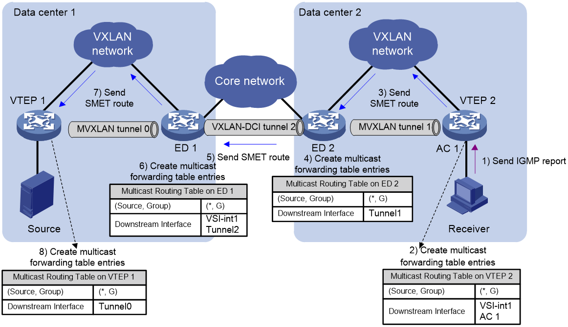
As shown in Figure 22, the process of routing release when passing multicast traffic through the default MDT forwarding group within a data center is as follows:
1. The multicast receiver, referred to as Receiver, transmits an IGMP report message, requesting to join the multicast group (*, G).
2. After receiving the IGMP report packet, VTEP 2 creates a Layer 3 multicast forwarding entry with the egress interface as the VSI virtual interface and the egress port connected to the Receiver's AC.
3. VTEP 2 transmits the SMET route carrying the (*,G) information to ED 2.
4. After receiving the SMET route, ED 2 generates a Layer 3 multicast forwarding entry. The egress interface is the multicast VXLAN tunnel within DC 2.
5. After modifying the next hop of the route to its own IP address, ED 2 continues to forward the SMET route to ED 1.
6. Upon receiving the SMET route, ED 1 generates a layer 3 multicast forwarding entry, with the egress interface being the VSI virtual interface corresponding to L3VNI, and the egress port points to the unicast VXLAN-DCI tunnel to ED 2.
7. ED 1 continues to forward the SMET route to VTEP 1.
8. Upon receiving the SMET route, VTEP 1 creates a Layer 3 multicast forwarding entry with the egress interface set to the multicast VXLAN tunnel within DC 1.
Figure 23 The process of route release when switching from default MDT to data MDT, assuming the L3VNI is the same.

The process of route release is as follows when the multicast traffic switches from default MDT to data MDT:
1. The multicast source-side VTEP (VTEP 1) transmits (Tx) the S-PMSI A-D route to ED 1, announcing (Annc) the multicast traffic and Data-group information (Info) that is pending switchover.
2. After receiving the S-PMSI A-D route, ED 1 joins the data MDT within DC 1.
3. ED 1 continues to advertise the S-PMSI A-D route to ED 2.
4. After receiving the S-PMSI A-D route, ED 2 replaces the source address of data MDT with its own address, and continues to advertise the S-PMSI A-D route to VTEP 2.
5. Upon receiving the route, VTEP 2 joins the data MDT within DC 2.
In the network shown in Figure 22, after completing the learning of Layer 3 multicast forwarding entries and establishing multicast VXLAN tunnels, the process of forwarding packets according to the Layer 3 multicast forwarding entries is as follows:
1. After VTEP 1 receives the multicast datagram sent by Source, it looks up the multicast forwarding entry and transmits the datagram to ED 1 through the multicast VXLAN tunnel via the egress interface.
2. After ED 1 removes the VXLAN encapsulation, it looks up the entry in the Layer 3 multicast forwarding table, re-encapsulates the packet with VXLAN, then transmits the packet to ED 2 via the VXLAN-DCI tunnel.
3. After the VXLAN encapsulation is removed by ED 2, it searches the Layer 3 multicast forwarding entry, re-encapsulates the packets, and passes them to VTEP 2 through the multicast VXLAN tunnel.
4. After VTEP 2 decapsulates VXLAN, it transmits the message to the multicast receiver.
EVPN VXLAN DCI Layer 3 multicast forwarding (L3VNI mapping)
In the scenario of interconnecting data centers, if the same tenant uses different L3VNI within each data center but still needs to conduct layer-three multicast communication across data centers, this issue can be resolved by mapping L3VNI.
The L3VNI mapping includes:
· Map the local VXLAN directly to the VXLAN used in another data center. When using this method, you only need to specify the mapping of the remote VXLAN on the ED of one data center.
· Local VXLANs on different data center EDs are mapped to the same VXLAN, which is called an intermediate VXLAN. When using this method, it's necessary to specify that the remote VXLAN to be mapped on all data center EDs is the intermediate VXLAN.
The L3VPN mapping is achieved by regenerating the S-PMSI A-D route and SMET route, and then intruding the S-PMSI A-D route and SMET route into the corresponding VPN-instance of the mapping L3VNI.
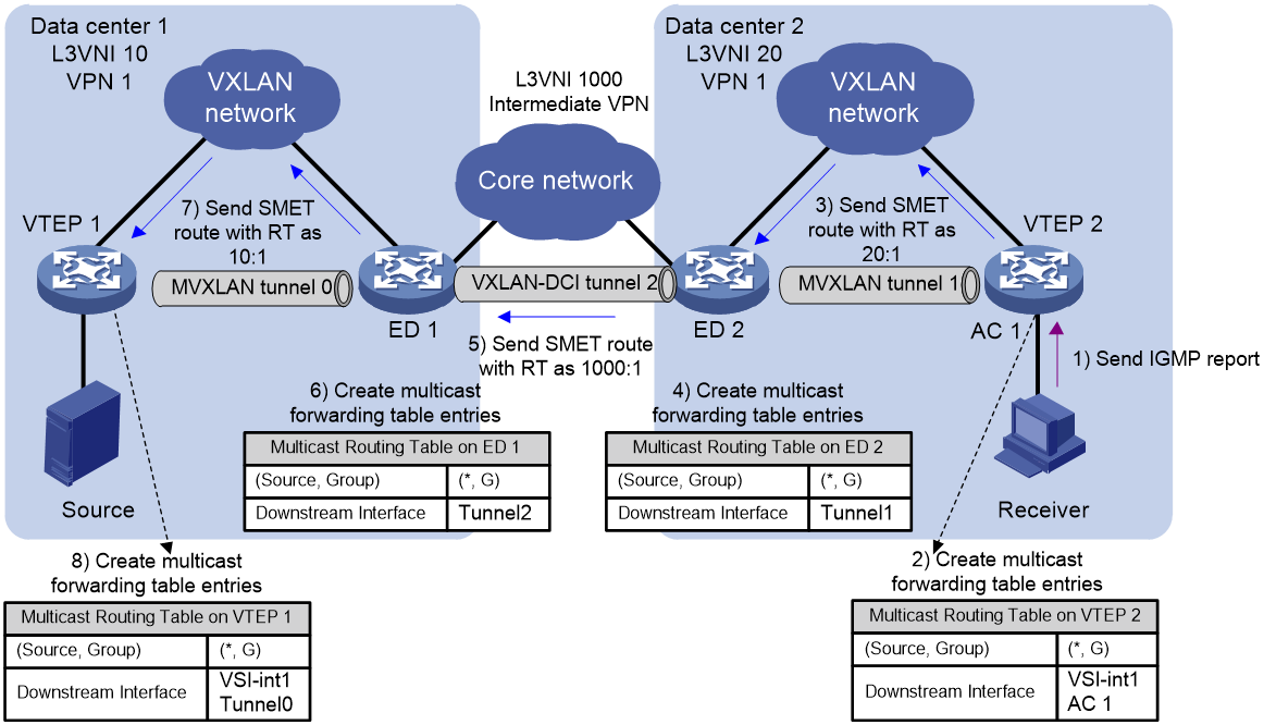
As shown in Figure 24, taking the mapping to the middle VXLAN as an example, when multicast traffic in the data center is forwarded through the default MDT forwarding group, the routing release process is as follows:
1. The Receiver, as a multicast recipient, transmits an IGMP report message to request joining the multicast group (*, G).
2. After VTEP 2 receives the IGMP report packet, it generates a Layer 3 multicast forwarding entry with the egress interface as the VSI virtual interface and the egress port connecting to the Receiver's AC.
3. VTEP 2 transmits the SMET route carrying the (*,G) information to ED 2.
4. 4. After receiving the SMET route, ED 2 creates a Layer 3 multicast forwarding entry with the egress interface set to the multicast VXLAN tunnel within DC 2.
5. ED 2, following the route regeneration rule, regenerates the SMET route to the middle VPN by modifying the RT and RD to match those of the middle VPN, and then forwards the route to ED 1.
6. Upon receiving the SMET route, ED 1 creates a Layer 3 multicast forwarding entry with the egress interface as the VSI virtual interface corresponding to L3VNI, and the egress port as the unicast VXLAN-DCI tunnel pointing to ED 2.
7. ED 1 regenerates the SMET route into VPN within DC 1 based on route regeneration rules, altering the RT and RD of the route to the RT and RD of VPN within DC 1. This route is then forwarded to VTEP 1.
8. After VTEP 1 receives the SMET route, it generates a Layer 3 multicast forwarding entry with the egress interface as the multicast VXLAN tunnel within DC 1.
Figure 25 The process of routing release when the default MDT switches to data MDT (L3VNI mapping).
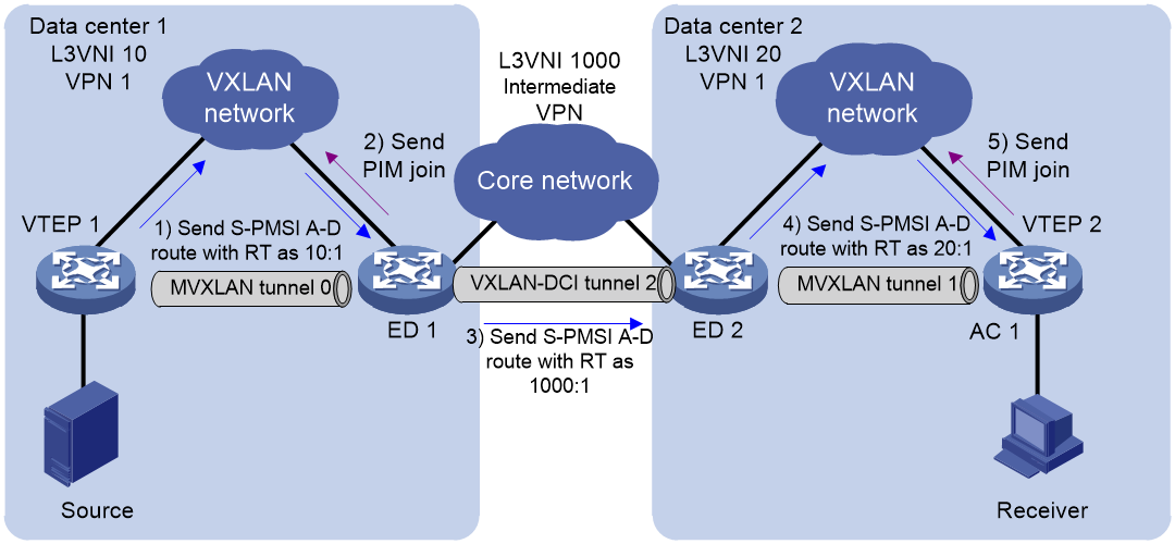
The process of routing release is as follows when multicast traffic switches from default MDT to data MDT.
1. The multicast source-side VTEP (VTEP 1) transmits (Tx) the S-PMSI A-D route to ED 1, announcing (Annc) the multicast traffic and Data-group information (Info) pending for switover.
2. Upon receiving the S-PMSI A-D route from ED 1, it joins the data MDT within DC 1.
3. Based on the route regeneration rule, ED 1 regenerates the SMET route to the intermediate VPN (modifying the route's RT and RD to the RT and RD of the intermediate VPN), and forwards this route to ED 2.
4. Upon receiving the S-PMSI A-D route, ED 2 replaces the source address of data MDT with its own address. It then regenerates the SMET route into DC 2's VPN based on the rule, adjusting the RT and RD of the route to match those of DC 2's VPN. Finally, this regenerated route is forwarded to VTEP 2.
5. Upon receiving the route, VTEP 2 joins the data MDT within DC 2.
In the network as shown in Figure 24, after completing the learning of Layer 3 multicast forwarding entries and establishing multicast VXLAN tunnels, the process of forwarding packets according to the Layer 3 multicast forwarding entries is as follows:
1. After VTEP 1 receives the multicast data packet sent by the multicast source, it looks up the Layer 3 multicast forwarding entry and forwards the packet to ED 1 through the egress multicast VXLAN tunnel. At this point, the L3VNI encapsulated in the packet is the L3VNI within DC 1.
2. After ED 1 removes the VXLAN encapsulation, it looks for the entry in the Layer 3 multicast forwarding table, re-encapsulates the message with VXLAN, and transmits the message to ED 2 through the VXLAN-DCI tunnel. At this point, the L3VNI used for encapsulating the message is the L3VNI of the intermediate VPN.
3. After ED 2 decapsulates the VXLAN, it looks up the entry in the level 3 multicast forwarding table, re-encapsulates the packet, and passes the packet to VTEP 2 through the multicast VXLAN tunnel. At this time, the L3VNI encapsulated for the packet is the L3VNI inside DC 2.
4. After VTEP 2 decapsulates the VXLAN, it transmits the message to the multicast receiver.
Layer 3 multicast DCI with dual ED support
In the scenario of EVPN data center interconnection, two ED devices can be deployed at the margin of the data center to enhance ED reliability and prevent single point failures. These two devices, using the same virtual IP (VIP), are turned into a single virtual ED device. They set up tunnels using the VIP with VTEP and remote ED, achieving redundancy protection and load sharing. The two ED devices within the same data center use different addresses for BGP peer addresses. They establish BGP EVPN neighbors with VTEP and remote ED separately, allowing load sharing within the Underlay network through routing protocol.
Figure 26 SMET Route Distribution in Layer 3 Multicast DCI with dual EDs

As shown in Figure 26, the process of routing during the transmission of multicast traffic through the default MDT forwarding group within the data center is as follows:
1. The multicast receiver, referred to as Receiver, transmits an IGMP report message, requesting to join the multicast group (*, G).
2. Upon receiving the IGMP report message, VTEP 2 generates a layer 3 multicast forwarding entry. The egress interface is the VSI virtual interface, and the egress port is the AC connected to the Receiver.
3. VTEP 2 establishes BGP EVPN neighbors with ED 3 and ED 4, and transmits SMET routes carrying (*,G) information (Info) to ED 3 and ED 4.
4. After receiving the SMET route, ED 3 and ED 4 create a Layer 3 multicast forwarding entry with the egress interface as the multicast VXLAN tunnel within DC 2.
5. ED 3 and ED 4, after modifying the next-hop address of the route to their virtual IP (VIP), continue to forward the SMET route to ED 1 and ED 2.
6. After receiving the SMET route, ED 1 and ED 2 generate multicast forwarding entries, with the egress interface being the VSI virtual interface corresponding to the L3VNI, and the egress port being the unicast VXLAN-DCI tunnel pointing to ED 3 OR ED 4. ED 3 and ED 4 have the same virtual IP (VIP) address, which is also the destination IP address of the unicast VXLAN-DCI tunnel.
7. ED 1 and ED 2 transmit the SMET route to VTEP 1.
8. After receiving the SMET route from ED 1 and ED 2, VTEP 1 creates a Layer 3 multicast forwarding table with the egress interface as the multicast VXLAN tunnel within DC 1.
Figure 27 Layer 3 multicast DCI supports dual ED network with S-PMSI A-D route
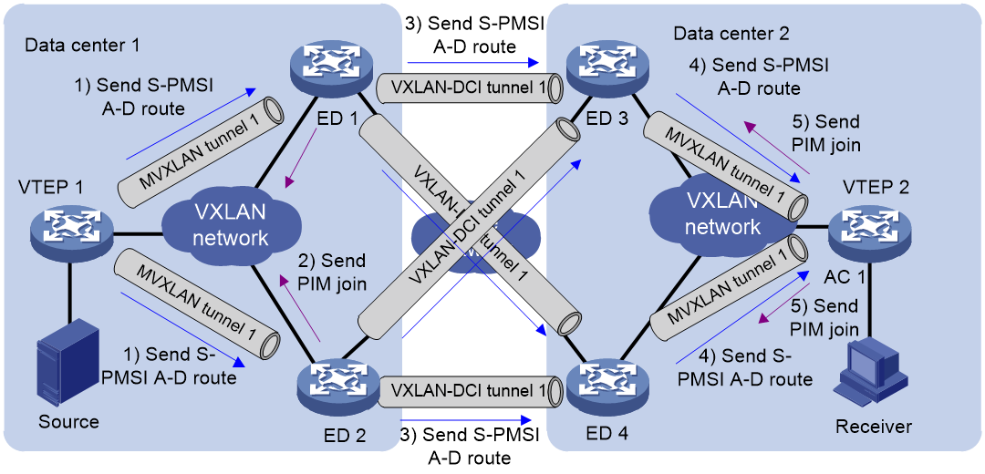
When multicast traffic switches from default MDT to data MDT, the route release process is as follows:
1. The multicast source-side VTEP (VTEP 1) transmits (Tx) S-PMSI A-D route to ED 1 and ED 2, announcing the multicast traffic and Data-group information (Info) that is pending for switchover.
2. Upon receiving S-PMSI A-D route, both ED 1 and ED 2 join the data MDT within DC 1.
3. ED 1 and ED 2 forward the S-PMSI A-D route to ED 3 and ED 4.
4. After receiving the S-PMSI A-D route, ED 3 and ED 4 replace the source address of data MDT with their own virtual IP (VIP) address. Then, they forward this route to VTEP 2.
5. Upon receiving the route, VTEP 2 joins the data MDT within DC 2.
Since Layer 3 multicast traffic is forwarded through multicast VXLAN tunnels, both EDs can receive the multicast traffic. At this point, one ED must be selected as the Designated Forwarder (DF) based on the multicast group address and the actual IP addresses of the EDs. Different multicast traffic may have different DFs to achieve load sharing of multicast traffic on the EDs.
In the network shown in Figure 26, after completing the learning of Layer 3 multicast forwarding entries and establishing multicast VXLAN tunnels, the process of forwarding packets according to the Layer 3 multicast forwarding entries is as follows:
1. After VTEP 1 receives the multicast data packet sent by the multicast source, it looks up the Layer 3 multicast forwarding entry and forwards the packet to both ED 1 and ED 2 through the egress multicast VXLAN tunnel.
2. After ED 1 and ED 2 decapsulate VXLAN, they determine whether they are the Designated Forwarder (DF) for this multicast traffic. If they are the DF, they search for an entry in the layer three multicast forwarding table, re-encapsulate the packet with VXLAN, and transmit the packet to ED 3 or ED 4 through the VXLAN-DCI tunnel. If they are not the DF, the ED will not forward the multicast traffic.
3. After removing the VXLAN encapsulation by ED 3 OR ED 4, the multicast forwarding entry is searched, the packet is re-encapsulated, and it is forwarded to VTEP 2 through the multicast VXLAN tunnel.
4. After VTEP 2 decapsulates VXLAN, it transmits the packet to the multicast receiver.
EVPN multicast supports DRNI
Overview of EVPN multicast support for DRNI mechanism
Typical networking
Multicast VXLAN utilizes the Distributed Resilient Network Interconnect (DRNI) function to create a virtual single device from two physical devices. This aggregation helps prevent network impacts from single-point device failure, thus enhancing the reliability of the multicast VXLAN network. In the multicast VXLAN network setup, both VTEP and Border devices support aggregation. These aggregated VTEP and Border devices can connect to both the multicast source and receivers.
The typical network of EVPN multicast supporting DRNI is shown as in Figure 28. VTEP 1 and VTEP 2 form a Distributed Relay (DR) (aggregation system), as do VTEP 3 and VTEP 4, and Border 1 and Border 2. The two VTEP/Borders that make up the DR system share the same virtual address and appear as a single virtual device. Other VTEP/Borders automatically establish a unicast VXLAN tunnel with this virtual device using this address. The source address of the multicast VXLAN tunnel also uses this virtual VTEP address. Due to the multicast RPF check mechanism of the Underlay network, a device will only join the multicast VXLAN tunnel of one device in the DR system. For instance, when VTEP 3 and VTEP 4 join the multicast VXLAN tunnel, they will only join one of the VTEP in VTEP 1 and VTEP 2, they will not join the multicast VXLAN tunnels of both VTEP 1 and VTEP 2 simultaneously.
Figure 28 Multicast VXLAN supports distributed aggregation networking.

User-side backup mechanism
The Multicast VXLAN feature supports the DRNI function. It syncs multicast traffic and join requests of multicast receivers (IGMP membership report messages OR PIM join messages) among member devices that form the DR system through the IPL (Intra-Portal Link, internal control link), keeping the information of multicast sources and receivers consistent on member devices. This forms a device-level backup. When a fault occurs on one member device (device fault, uplink/downlink link faults, etc.), another member device can forward the multicast traffic, thus avoiding disruptions in multicast traffic forwarding.
In the network architecture shown in Figure 28, the backup mechanism at the customer site is as follows:
· Multicast source-side backup: After multicast source Source 1 is connected via DRNI, the multicast traffic from Source 1 is transmitted to one of the devices in VTEP 1 and VTEP 2. The VTEP that receives the multicast traffic synchronizes the multicast traffic to the other VTEP through the IPL link, thereby achieving the presence of multicast traffic on both VTEP 1 and VTEP 2.
· Multicast receiver side backup: After accessing via DRNI, the multicast receiver's join request will be sent to one of the devices in VTEP 3 and VTEP 4. The VTEP which receives the join request passes it through the IPL link to sync with another VTEP, thereby establishing multicast forwarding entries on both VTEP 3 and VTEP 4. The egress interface for these entries is set as the DR port.
Multicast traffic sharing
Upon receiving multicast traffic, the Designated Router (DR) device on the multicast source side implements load sharing using the parity principle. Member devices with odd DR system numbers forward traffic with odd multicast group addresses, while member devices with even DR system numbers forward traffic with even multicast group addresses. When one device encounters a fault, another device can take over its work to prevent traffic forwarding disruption.
|
|
NOTE: The principle of odd and even load sharing for multicast traffic on DR devices only applies to layer three multicast forwarding and does not work on layer two multicast forwarding. |
Layer 2 multicast supports DRNI
Typical networking
As shown in Figure 29, in the Layer 2 multicast support for DRNI networking, only multicast receivers are supported to connect via DRNI, not multicast sources. Moreover, only head-end replication is supported for traffic forwarding.
Figure 29 Typical networking configuration for Layer 2 multicast supporting DRNI

Process of route distribution and traffic forwarding under normal conditions
When the DR device is operating normally, the process of route release and multicast forwarding entry generation within the DRNI networking supported by Layer 2 multicast is as follows:
1. The multicast receiver (Receiver) transmits an IGMP report message to request joining a multicast group (*, G). The IGMP report message is sent to either VTEP 3 or VTEP 4 (VTEP 3 is used as an example in the following text).
2. After VTEP 3 listens to the IGMP report message through IGMP Snooping, it generates a Layer 2 multicast forwarding entry (*,G), with the exit port being the DR port.
3. VTEP 3 syncs the IGMP report message to VTEP 4 via the IPL link. At the same time, VTEP 3 transmits the SMET route to VTEP 1 and VTEP 2.
4. Upon receiving the synchronous IGMP report, VTEP 4 also generates a Layer 2 multicast forwarding entry (*,G), with the exit port being the DR port. Simultaneously, VTEP 4 transmits SMET routes to VTEP 1 and VTEP 2.
5. Upon receiving the SMET route, VTEP 1 and VTEP 2 generate an entry for the Layer 2 multicast forwarding table. The output port is the unicast VXLAN tunnel interface that connects to the virtual addresses of VTEP 3 and VTEP 4.
When the DR device operates normally, after completing the release of routes and generating multicast forwarding entries, the process of packet forwarding is as follows:
1. The multicast source, Source, transmits traffic to VTEP 1.
2. VTEP 1 transmits traffic to either VTEP 3 or VTEP 4 through a unicast VXLAN tunnel.
3. After receiving multicast traffic, VTEP 3 OR VTEP 4 forwards it to the local multicast receivers.
Fault protection
When a DR device on the multicast receiver side experiences a fault, the IGMP report message can be sent to the non-faulty DR device, and IGMP report synchronization can still be achieved between DR devices through the IPL link. Traffic forwarding will not be affected.
When there is a link fault in the receiver-side DR system of the multicast, the IGMP report cannot synchronize between DR devices. Only the VTEP that receives the IGMP report will transmit the SMET route to the source-side VTEP of multicast, achieving traffic diversion without disrupting multicast traffic forwarding.
Layer 3 multicast supports DRNI
Process of establishing multicast VXLAN tunnels under normal conditions
As shown in Figure 30, when the DR device is working normally, the multicast VXLAN tunnel setup process is initiated from the DR system composed of VTEP 1 and VTEP 2.
1. VTEP 1 or VTEP 2 transmits S-PMSI A-D route, carrying multicast VXLAN tunnel information, where the source address of the tunnel is the virtual address of VTEP 1 and VTEP 2.
2. Upon receiving the S-PMSI A-D routes transmitted by VTEP 1 OR VTEP 2, both Spine 1 and Spine 2, VTEP 3 and VTEP 4 send a multicast join request (Mtunnel join), attempting to join the multicast VXLAN tunnel of VTEP 1 OR VTEP 2. Each device looks up its local unicast routing table, finds the upstream addresses towards the virtual addresses of VTEP 1 and VTEP 2, and sends the multicast join request to VTEP 1 OR VTEP 2 hop-by-hop. There could be multiple possible situations for the multicast distribution tree of the multicast VXLAN tunnel with VTEP 1 OR VTEP 2 as the starting dot, which depends on the unicast routing table on each device in the network and the selection rule of the multicast RPF route.
Figure 30 The process of setting up a multicast VXLAN tunnel under normal circumstances.

Route distribution and traffic forwarding process under normal conditions
When the DR device is working normally, the process of route release is as follows:
1. The Receiver (a multicast recipient) transmits an IGMP report message, requesting to join the multicast group (*, G). The IGMP report message is sent to either VTEP 3 OR VTEP 4 (with VTEP 3 used as an example in the following text).
2. After VTEP 3 receives the IGMP report message, it generates a layer 3 multicast forwarding entry.
3. VTEP 3 synchronizes IGMP report messages to VTEP 4 via the IPL link. At the same time, VTEP 3 transmits SMET routes to VTEP 1 and VTEP 2.
4. Upon receiving the synchronous IGMP report, VTEP 4 also generates a Layer 3 multicast forwarding entry. Simultaneously, VTEP 4 transmits the SMET route to VTEP 1 and VTEP 2.
5. Upon receiving the SMET route, VTEP 1 and VTEP 2 generate Layer 3 multicast forwarding entries, with the egress port being the multicast VXLAN tunnel interface.
Figure 31 The process of route release when the DR device is working normally.

When the DR device is functioning properly, after completing the route release and generating the multicast forwarding entries, the process of message forwarding is as follows:
1. The multicast source, Source, transmits traffic to VTEP 1.
2. After receiving the multicast traffic, VTEP 1 synchronizes the traffic to VTEP 2 through the IPL link.
3. VTEP 1 and VTEP 2 forward traffic to the remote VTEP through the multicast VXLAN tunnel.
4. After receiving multicast traffic through multicast VXLAN tunnel, VTEP 3 and VTEP 4 forward multicast traffic to multicast receivers on the DR side according to the principle of odd-even load sharing.
Multicast source-side fault protection
Establishing multicast VXLAN tunnel
After a multicast source-side IPL link fault, multicast traffic cannot sync between VTEP 1 and VTEP 2. Since both VTEP 1 and VTEP 2 need to transmit multicast traffic, they should use their actual IP addresses as the source address to establish multicast VXLAN tunnels. Starting with the DR system composed of VTEP 1 and VTEP 2, the process of establishing multicast VXLAN tunnels is as follows:
1. VTEP 1 or VTEP 2 transmit S-PMSI A-D route, carrying multicast VXLAN tunnel information, where the source address of the tunnel is the actual IP address of VTEP 1 and VTEP 2 respectively. VTEP 1 and VTEP 2 each establish a multicast VXLAN tunnel with their respective IP addresses as the starting point. These two multicast VXLAN tunnels each have their own independent multicast distribution tree.
2. Taking VTEP 1 as an example, upon receiving the S-PMSI A-D routing transmitted by VTEP 1, Spine 1 and Spine 2, as well as VTEP 3 and VTEP 4, send multicast join requests and attempt to join VTEP 1's multicast VXLAN tunnel. Each device searches its local unicast routing table to find the upstream address to VTEP 1 and sends hop-by-hop multicast join requests to VTEP 1. There are various possible scenarios for the multicast distribution tree of the multicast VXLAN tunnel starting from VTEP 1, which depends on the unicast routing table on each device in the network, and the selection rules of multicast RPF routing.
Route release
When there is a multicast source side IPL fault, the route release and traffic forwarding process are the same as during normal operation of the DR system. For more details, please refer to "Route distribution and traffic forwarding process under normal conditions.”
Traffic forwarding
When a link fault occurs on the multicast source side IPL, the process of message forwarding is as follows:
1. The multicast source (Source) transmits traffic to VTEP 1.
2. After receiving the multicast traffic, VTEP 1 forwards the traffic to the remote VTEP via the multicast VXLAN tunnel. The source address of the multicast VXLAN tunnel is the address of VTEP 1. At this time, VTEP 2 cannot receive the multicast traffic and will not forward it.
3. After VTEP 3 and VTEP 4 receive multicast traffic through the multicast VXLAN tunnel, they forward multicast traffic to the multicast receiver on the DR side according to the odd-even load sharing principle.
Multicast receiver-side fault protection
When a DR device on the multicast receiver's side encounters a fault, the IGMP report message can be sent to the non-faulty DR device. The IGMP report can still be synchronized between the DR devices via the IPL link without affecting the traffic forwarding.
When the IPL link fault occurs in the multicast receiver side DR system, the IGMP report cannot be synchronized between the DR devices. Only the VTEP that receives the IGMP report will transmit the SMET route to the multicast source side VTEP, realizing traffic diversion. The multicast traffic forwarding will not be disrupted.
Typical network applications
Urban rail multicast typical networking (source in data center, receivers at stations)
As depicted in Figure 32, OSPF operates within the station core network and access network in the city rail network, while EVPN operates within the data center network. To provide services such as broadcast (PA) and passenger information system (PIS) in the city rail network, the multicast source needs to be deployed in the data center network, and the multicast receiver needs to be deployed in the station core network. Both multicast sources and receivers are connected via DRNI to improve the reliability of traffic forwarding. Within the data center network, the Leaf device receives the traffic transmitted by the multicast source, encapsulates the multicast traffic into VXLAN via EVPN multicast technology, and forwards the encapsulated traffic to the Border. The Border device decapsulates the multicast traffic and transmits it to the access network. Devices in the access network and core network then forward the traffic to the multicast receiver through IP multicast technology.
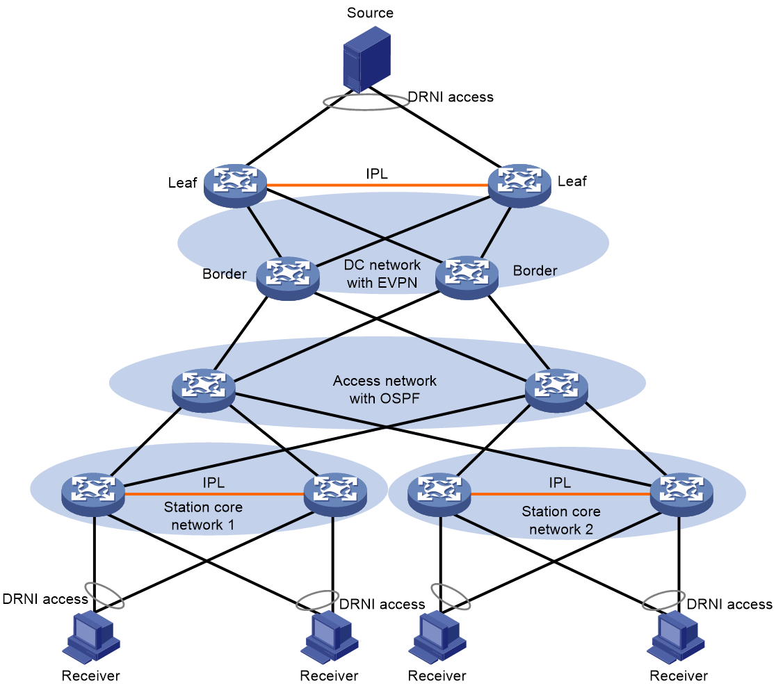
Urban rail multicast typical networking (source at station, receivers in data center)
As shown in Figure 33, within the urban rail network, OSPF operates within the station core network and the access network; EVPN operates within the data center network. To provide services such as CCTV video monitoring systems in the urban rail network, the multicast source needs to be deployed in the station core network, and the multicast receiver needs to be deployed in the data center network. Both multicast sources and receivers access through DRNI to enhance the reliability of traffic forwarding. The traffic sent by the multicast source is transmitted to the Border via IP multicast technologies, from the station core network and the access network. The Border encapsulates the multicast traffic using EVPN multicast technology into VXLAN and forwards the encapsulated traffic to the Leaf. The Leaf decapsulates the multicast traffic and transmits it to the multicast receiver.
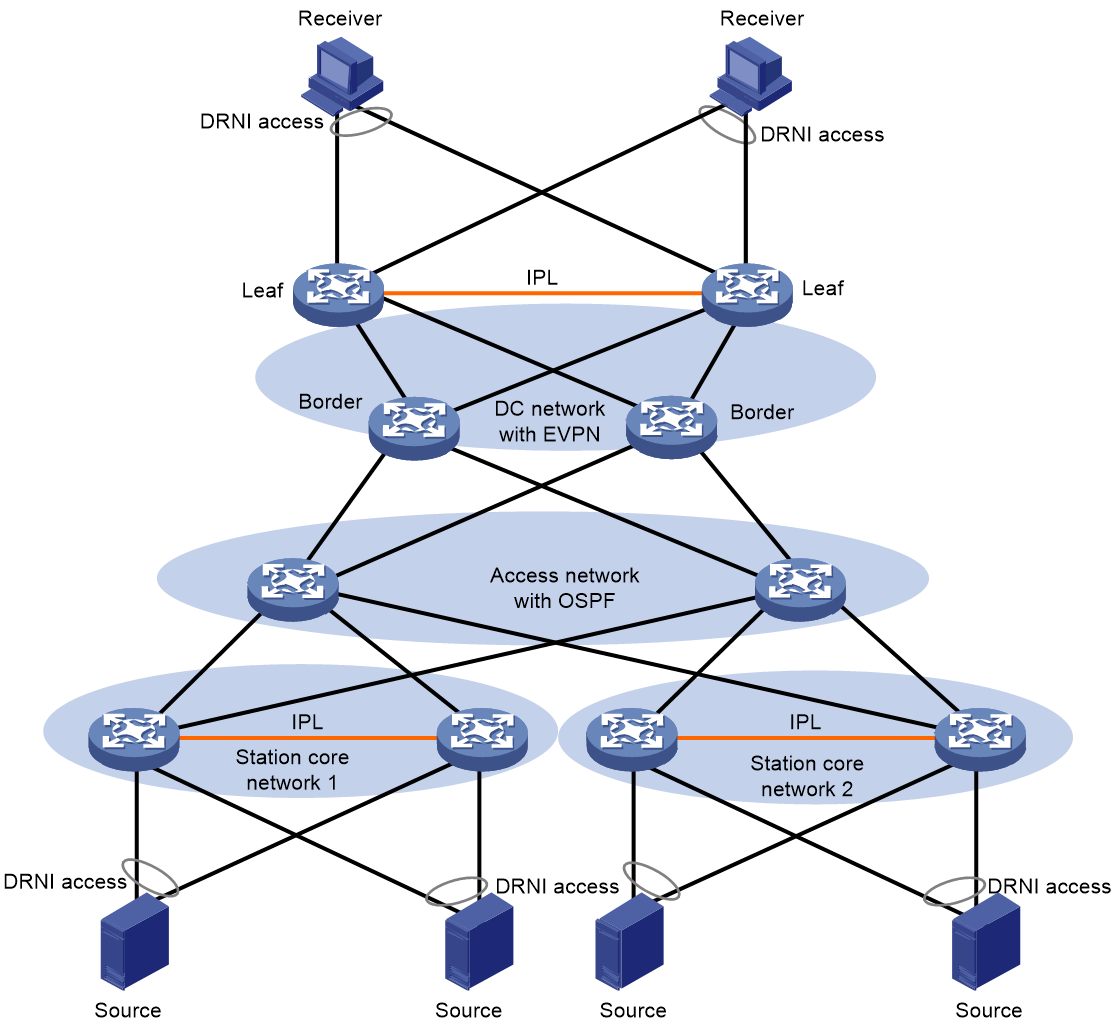
Urban rail multicast typical networking (both station and data center have sources and receivers)
As shown in Figure 34, within the urban rail network, OSPF runs in the core network and access network of stations; EVPN runs in the data center network. To provide services such as Integrated Supervisory Control System (ISCS) in the urban rail network, multicast sources and multicast receivers need to be deployed in both the station core network and data center network, and a single device may also serve as both a multicast source and receiver. Multicast sources and receivers are connected via DRNI to enhance traffic forwarding reliability. Devices within the station core network and access network employ IP multicast technology to forward multicast traffic, while devices within the data center network utilize EVPN multicast technology to forward multicast traffic.

