- Released At: 08-11-2024
- Page Views:
- Downloads:
- Table of Contents
- Related Documents
-
AI Noise Reduction Technology White Paper
Copyright © 2024 New H3C Technologies Co., Ltd. All rights reserved.
No part of this manual may be reproduced or transmitted in any form or by any means without prior written consent of New H3C Technologies Co., Ltd.
Except for the trademarks of New H3C Technologies Co., Ltd., any trademarks that may be mentioned in this document are the property of their respective owners.
The content in this article is general technical information, and some information may not apply to the product you purchased.
Contents
PWM-based linear speed adjustment
About PWM-based linear speed adjustment
PID speed adjustment mechanism
About PID + linear speed adjustment
Overview
The rapid development of integrated circuits and other technologies has greatly improved the performance of electronic devices such as chips, while the physical size has become increasingly smaller, resulting in a significant increase in power density of electronic devices. To resolve the high temperature issue during device operation, the device typically uses the air-cooling system for heat dissipation. However, the accompanying fan noise has become an urgent problem to be addressed.
H3C has launched the second-generation linear speed control scheme for CT products. This scheme achieves low fan speed when the device temperature is low and automatically accelerates the fan speed when the device temperature is high, speeding up heat dissipation. For the pure linear speed control scheme, the greater the fluctuation in fan speed, the higher the noise. The PID+ linear speed control scheme is developed to resolve this issue.
The PID + linear speed control scheme is the third-generation speed control scheme for CT products launched by H3C. Compared with the second-generation pure linear speed control scheme, the third-generation scheme changes the linear speed control's normal temperature segment to PID speed control. This can further reduce the fan speed of the device at normal temperature to achieve energy saving and noise reduction.
Technical Introduction
PWM-based linear speed adjustment
About PWM-based linear speed adjustment
Based on pulse width modulation (PWM), the device can automatically adjust the fan speed according to the temperature of MPUs, service modules, switching fabric modules, and so on. When the device temperature does not exceed the minimum value for fan acceleration, the fan speed is very low and the noise is very small, thus saving power consumption. When the device temperature rises, the fan automatically accelerates to speed up heat dissipation.
PWM is a technique that uses the digital output of a microprocessor to control analog circuits. At a certain frequency, PWM adjusts the fan speed by outputting different voltages depending on different duty cycles. The following are basic PWM concepts:
· Frequency (f)—Number of times the signal transitions from high to low and back to high within one second, which is the number of cycles per second of PWM, in Hz. For example, if the frequency is 50 Hz, there are 50 PWM cycles in one second.
· Pulse period (T)—Time from the start of one pulse to the next, in seconds. The calculation formula is T=1/f.
· Pulse width—Duration of the high-level signal within one pulse period.
· Duty cycle—Ratio of the duration of the high-level signal to the total period of one pulse period, in percentage. For example, if the pulse period is 10 ms and the pulse width is 8 ms, the duty cycle is 80%.
A pulse period is as shown in Figure 1.
Figure 1 Pulse period and pulse width

PWM can adjust the duty cycle of the output voltage to obtain different analog voltages. As shown in Figure 2, assume that the high voltage level is 5 V and the low voltage level is 0 V. At a certain frequency, if you have 50% duty cycle, the output analog voltage would be 2.5 V. If you have 75% duty cycle, the output analog voltage would be 3.75 V. If you have 20% duty cycle, the output analog voltage would be 1 V.
Figure 2 PWM analog voltage output

Speed adjustment mechanism
The device can control the fan speed by adjusting the duty cycle of the fan voltage based on the chip junction temperature. The fan speed curve is shown in the figure below. As shown in Figure 3, within the specified temperature range for fan speed adjustment, the fan speed increases as the device temperature increases.

If you are more concerned about noise or heat dissipation, the fan speed adjustment can be modified as follows:
Contact H3C Support to modify the default values of Tlow and Thigh to flexibly meet different noise requirements. As shown in Figure 4, increase the values of Tlow and Thigh by 10 to modify the fan speed range from 55°C-85°C (131°F-185°F) to 65°C -95°C (149°F -203°F).
|
|
NOTE: The default values vary by device. |
Figure 4 Modifying the default values of Tlow and Thigh

PID control
About PID control
PID control, also known as proportional-integral-derivative control, is a control method defined by the principles of automatic control, as shown in Figure 5. PID control utilizes the control deviation between the setpoint and the actual output to generate a control signal, which is formed by linearly combining the proportional, integral, and derivative terms. This control signal is applied to the controlled object for control purposes.
As shown in Figure 5, the elements of PID control operate as follows:
· Proportional (P)—Instantly and proportionally reflects the deviation signal of the control system. Once a deviation occurs, the controller immediately generates a control action to reduce the error. When the deviation equals zero, the control action is also zero. Therefore, proportional control is adjusted based on the deviation, which is differential adjustment.
· Integral (I)—Memorizes errors, mainly used to eliminate the steady state error and improve system accuracy. The strength of integral action depends on the integral time constant Ti (system preset for adjusting integral strength). The larger the Ti, the weaker the integral action, and vice versa.
· Differential (D)—Reflects the trend of changes in the deviation signal (change rate) and introduces an effective early correction signal in the system before the deviation signal becomes too large. This can speed up the system's response speed and reduce the adjustment time.
In practical applications, P, PI, PD, or PID control can be adopted as needed.
Figure 5 PID control mechanism

PID speed adjustment mechanism
The device will preset an SP (SetPoint) value in the factory defaults, which is constant and cannot be changed from the CLI. The PID algorithm intelligently controls the fan speed to make the device temperature approach the SP value. When the temperature drops below the SP value, the fan speed decreases. When the temperature is higher than the SP value, the fan speed increases.
PID speed adjustment optimizes the relevant parameters of the PID fan control unit to achieve the following system responses:
· Minimum overshoot of the temperature at each hotspot.
· Each hotspot temperature reaches equilibrium state in a short time.
· The fan speed oscillates slightly.
|
|
NOTE: · Hotspot temperature: Temperature of the hotspot temperature sensor on the device. · Overshoot: Amplitude exceeding the set value. |
PID + linear speed adjustment
About PID + linear speed adjustment
The PID algorithm is simple, easy to implement, and can be applied widely, but it also has drawbacks such as slower response time. When the device temperature changes, the PID algorithm requires some time to adjust the fan speed. Therefore, the new generation speed adjustment scheme retains linear speed adjustment in the high temperature range, fully utilizing the advantages of fast linear speed response, ensuring the safety and reliability of the device during high temperature operation. In addition, the new generation speed adjustment also defines multiple modes, including silent mode, balanced mode, and low-temperature mode.
To specify the following fan operating modes, execute the fan auto-control-mode command:
· balance: Configures the fan to operate in a balanced way. In this mode, the fan speed is lower than the low-temperature mode and higher than the silence mode to provide balanced noise control and cooling performance.
· low-temperature: Configure the fan to operate in enhanced cooling mode. The fan speed is higher in this mode, which prioritizes the device's operation at lower temperatures, reduces temperature fluctuations, and improves overall reliability. However, this mode will increase the power consumption of the device and increase the noise compared to other modes.
· silence: Configure the device to operate in silent mode. In this mode, the fan speed is lower and the noise is smaller, but the device temperature will increase relatively. This mode applies to noise-sensitive environments.
Speed adjustment mechanism
When the fan speed is between Nlow and Nmid and the device temperature is lower than Tlow, PID speed adjustment is adopted. In other cases, linear speed adjustment is adopted. The speed adjustment is as shown in Figure 6.

When the device temperature is lower than Tlow, using PID control can keep the fan at a lower speed, allowing the device temperature to stay near the SP value. Compared to pure linear speed adjustment, this adjustment method can reduce fan speed, save energy, and reduce noise. When the device temperature is greater than Tlow, linear speed adjustment is adopted, which provides more positive responses to prevent device overtemperature.
As shown in Figure 7, compared with pure linear speed adjustment, PID control can effectively control the fan speed to keep the fan speed at a lower level.
Figure 7 Fan speed adjustment comparison
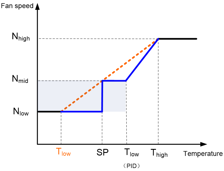
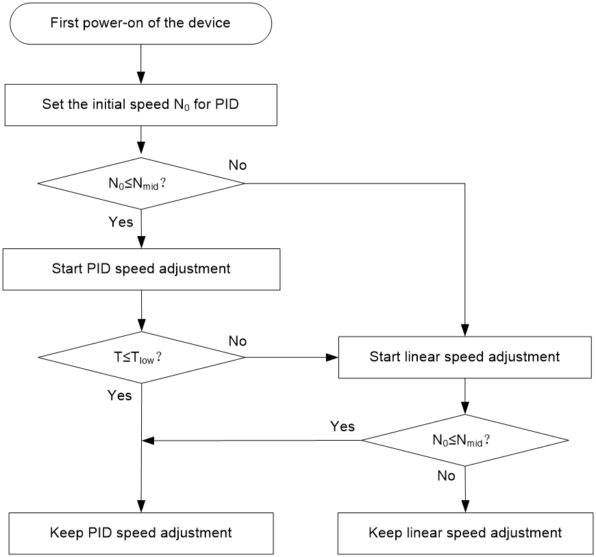
Figure 8 shows the workflow of PID + linear speed adjustment.
Figure 8 PID + linear speed adjustment workflow
Noise testing
About noise testing
This example uses the S5580X-48S4YC-HI switch for testing, and the test configuration is shown in Table 1.
|
Item |
Description |
|
Product configuration |
Standard configuration: No expansion cards, half of the ports are inserted with short-distance transceiver modules or cables |
|
Speed adjustment policy |
· TC1: Linear speed adjustment + 180W standard power supply · TC2: Linear speed adjustment + 180W noise-reduction power supply · TC3: PID comprehensive speed adjustment + 180W standard power supply · TC4: PID comprehensive speed regulation + 180W noise-reduction power supply (Noise-reduction power supplies support noise reduction compared to standard power supplies.) |
|
Airflow direction |
Fan module airflow direction (This example uses FAN-40B-1-F and FAN-40F-1-F fan modules): · Air intake: From the port side to the power supply side. · Air exhaust: From the power supply side to the port side. |
Test data
The test data under different temperatures are as shown in Table 2, Table 3, and Table 4.
Table 2 Test data in a 25°C (77°F) environment
|
Ambient temperature |
Product configuration |
Speed adjustment policy |
Fan direction |
Noise/dBA |
|
25°C |
Standard configuration |
TC1 |
Air intake |
46 |
|
Air exhaust |
45.6 |
|||
|
TC2 |
Air intake |
39.3 |
||
|
Air exhaust |
39.6 |
|||
|
TC3 |
Air intake |
44.7 |
||
|
Air exhaust |
44.9 |
|||
|
TC4 |
Air intake |
36.4 |
||
|
Air exhaust |
38.6 |
Table 3 Test data in a 35°C (95°F) environment
|
Operating temperature |
Product Configuration |
Speed adjustment policy |
Fan direction |
Noise/dBA |
|
35°C |
Standard configuration |
TC1 |
Air intake |
51.3 |
|
Air exhaust |
51 |
|||
|
TC2 |
Air intake |
49.3 |
||
|
Air exhaust |
49 |
|||
|
TC3 |
Air intake |
46 |
||
|
Air exhaust |
45.6 |
|||
|
TC4 |
Air intake |
39.3 |
||
|
Air exhaust |
39.6 |
Table 4 Test data in a 50°C (122°F) environment
|
Ambient temperature |
Product configuration |
Speed adjustment policy |
Fan direction |
Noise/dBA |
|
50°C |
Standard configuration |
TC1 |
Air intake |
62.7 |
|
Air exhaust |
65.1 |
|||
|
TC2 |
Air intake |
62.7 |
||
|
Air exhaust |
65.1 |
|||
|
TC3 |
Air intake |
51.3 |
||
|
Air exhaust |
51 |
|||
|
TC4 |
Air intake |
49.3 |
||
|
Air exhaust |
49 |
Noise reduction benefits
Table 5 Speed adjustment policy description
|
Speed adjustment policy |
Description |
|
TC1 |
Linear speed adjustment + 180W standard power supply |
|
TC2 |
Linear speed adjustment + 180W noise-reduction power supply |
|
TC3 |
PID comprehensive speed adjustment + 180W standard power supply |
|
TC4 |
PID comprehensive speed regulation + 180W noise-reduction power supply |
|
|
NOTE: Different noise reduction types represent the noise reduction benefits from different speed adjustment policies. For example, TC2-TC4 represents the noise reduction effect of using PID comprehensive speed control compared to pure linear speed adjustment with the same 180W noise-reduction power supply. |
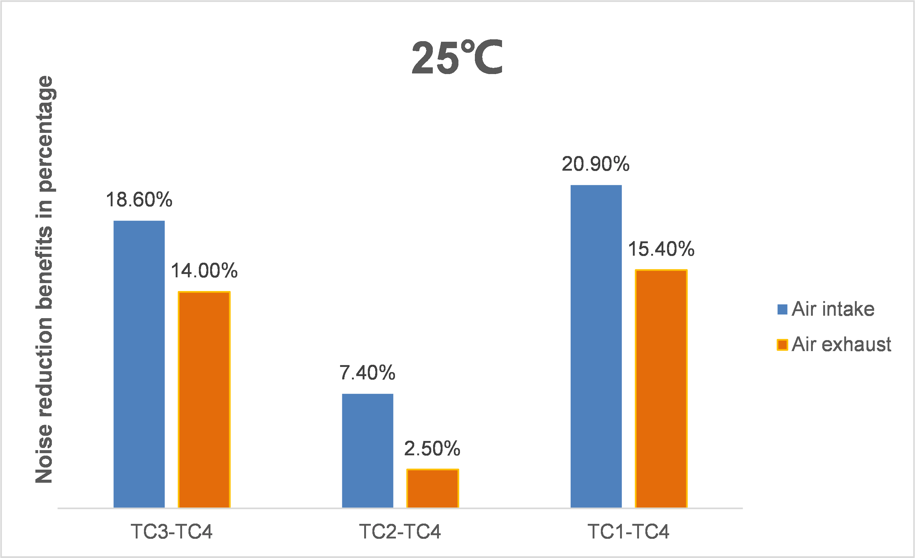
The noise reduction benefits in a 25°C environment are as shown in Table 6 and Figure 9:
· When the ambient temperature is low, the fan speed of the device remains low. The noise generated by the device is not significant regardless of the speed adjustment policy, so the noise reduction benefits of TC2-TC4 are not obvious.
· A noise reduction power supply itself supports noise reduction, so the noise reduction benefits of TC3-TC4 and TC1-TC4 are significant.
Table 6 Test data in a 25°C environment
|
Temperature |
Noise reduction type |
Airflow direction |
Noise reduction benefit/dBA |
Noise reduction benefits in percentage |
|
25°C |
TC3-TC4 |
Air intake |
8.3 |
18.6% |
|
Air exhaust |
6.3 |
14.0% |
||
|
TC2-TC4 |
Air intake |
2.9 |
7.4% |
|
|
Air exhaust |
1 |
2.5% |
||
|
TC1-TC4 |
Air intake |
9.6 |
20.9% |
|
|
Air exhaust |
7 |
15.4% |
Figure 9 Test data in a 25°C environment
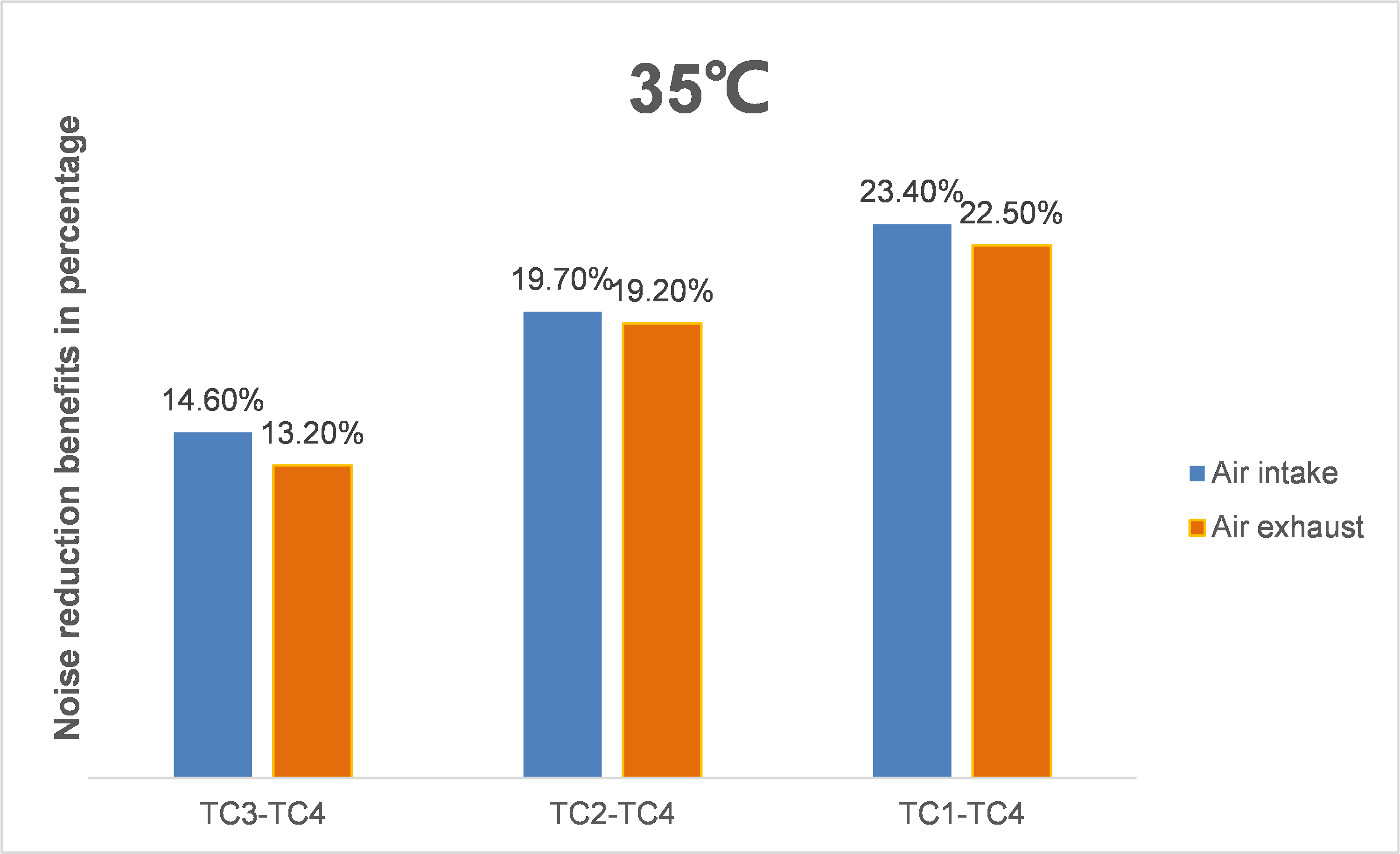
The noise reduction benefits in a 35°C environment are as shown in Table 7 and Figure 10.
The overall fan speed increases as the ambient temperature rises. Compared to linear speed adjustment, PID speed adjustment can effectively control the fan speed and reduce device noise. With noise-reduction power supplies, PID speed adjustment can provide significant noise reduction benefits in the three cases of TC3-TC4, TC2-TC4, and TC1-TC4.
Table 7 Test data in a 35°C environment
|
Temperature |
Noise reduction type |
Airflow direction |
Noise reduction benefit/dBA |
Noise reduction benefits in percentage |
|
35°C |
TC3-TC4 |
Air intake |
6.7 |
14.6% |
|
Air exhaust |
6 |
13.2% |
||
|
TC2-TC4 |
Air intake |
9.7 |
19.7% |
|
|
Air exhaust |
9.4 |
19.2% |
||
|
TC1-TC4 |
Air intake |
12 |
23.4% |
|
|
Air exhaust |
11.4 |
22.5% |
Figure 10 Test data in a 35°C environment
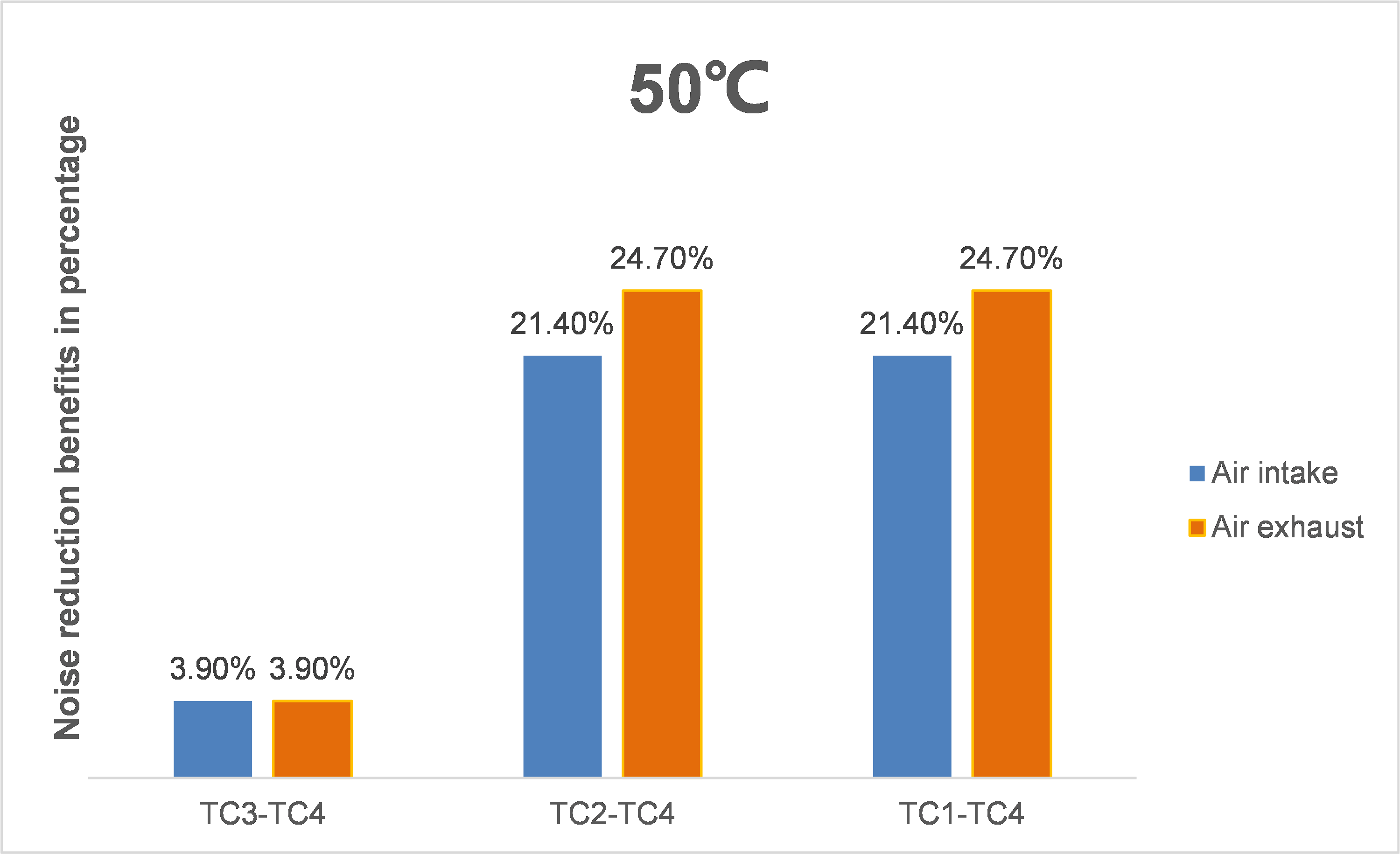
The noise reduction benefits in a 50°C environment are as shown in Table 8 and Figure 11.
· The ambient temperature further increases, the fan speed becomes higher, and the overall equipment noise increases. The noise reduction effect of PID speed adjustment is more obvious, with significant noise reduction benefits for TC2-TC4 and TC1-TC4.
· Due to the increase in ambient temperature, the fan speed of the noise reduction power supply increases, causing an increase in noise and a decrease in the noise reduction benefits of TC3-TC4.
Table 8 Test data in a 50°C environment
|
Temperature |
Noise reduction type |
Airflow direction |
Noise reduction benefits/dBA |
Noise reduction benefits in percentage |
|
50°C |
TC3-TC4 |
Air intake |
2 |
3.9% |
|
Air exhaust |
2 |
3.9% |
||
|
TC2-TC4 |
Air intake |
13.4 |
21.4% |
|
|
Air exhaust |
16.1 |
24.7% |
||
|
TC1-TC4 |
Air intake |
13.4 |
21.4% |
|
|
Air exhaust |
16.1 |
24.7% |
Figure 11 Test data in a 50°C environment
Summary
The following conclusions can be obtained from the above test data:
· Regardless of a low-temperature environment (25°C) or a high-temperature environment (50°C), the new generation PID comprehensive speed adjustment can bring good noise reduction effects, especially used with noise reduction power supplies.
· For different fan module airflow directions, the generated noise varies, and the noise reduction effect brought by PID comprehensive speed adjustment also varies. However, good positive effects can be achieved overall.
Application scenarios
The H3C third-generation intelligent speed adjustment solution achieves precise fan speed control, realizing dynamic adjustment under different workloads, making the fan operation smoother and quieter. At the same time, the third-generation intelligent speed adjustment technology can also improve energy-saving ability, reduce power consumption, helping enterprises save energy and reduce operating costs. Compared with traditional fan speed adjustment methods, the intelligent speed adjustment has higher safety, stability, and reliability, and can meet more production needs.
In summary, the new generation speed adjustment achieves energy saving and noise reduction of the device in typical temperature configurations, while also ensuring fast response in high temperature environments and guaranteeing equipment reliability. It considers both energy saving and noise reduction. Therefore, the new generation speed adjustment solution is widely applicable in various practical scenarios of customers, and it has multiple speed adjustment modes, which can meet different requirements and improve their actual application experience.
Applicable products
· S5580X-HI switch series
· S5580S-EI switch series
· S5580X-EI switch series
