| Title | Size | Downloads |
|---|---|---|
| BIER Technology White Paper-6W100-book.pdf | 1.16 MB |
- Table of Contents
- Related Documents
-
| Title | Size | Download |
|---|---|---|
| book | 1.16 MB |
BIER Technology White Paper
Copyright © 2024 New H3C Technologies Co., Ltd. All rights reserved.
No part of this manual may be reproduced or transmitted in any form or by any means without prior written consent of New H3C Technologies Co., Ltd.
Except for the trademarks of New H3C Technologies Co., Ltd., any trademarks that may be mentioned in this document are the property of their respective owners.
The content in this article is general technical information, some of which may not be applicable to the product you have purchased.
Supported message encapsulation types
G-BIER technology implementation
NG MVPN over G-BIER control plane
Operation mechanism of NG MVPN over G-BIER
NG MVPN over G-BIER forwarding process
Reliability protection of G-BIER
Fault detection and switchover
G-BIER Ping operating mechanism
Operation mechanism of G-BIER Tracert
BIERv6 technical implementation
NG MVPN over BIERv6 control plane
H3C NG MVPN over BIERv6 run mechanism
NG MVPN over BIERv6 forwarding process
Reliability protection of BIERv6
Public network multicast scenario
Overview
Background
In traditional IP multicast and multicast VPN technologies, devices must establish a multicast distribution tree for each multicast flow. Every node in the distribution tree needs to be aware of the multicast service and maintain multicast flow state. For example, in public network PIM multicast, a PIM multicast distribution tree must be established for each multicast flow. In NG MVPN, a P2MP tunnel must be set up for each multicast flow, which is equivalent to establishing a P2MP multicast tree. With the large-scale deployment of multicast services, the number of multicast distribution trees that need maintenance has increased sharply. This results in a large amount of multicast flow state that needs to be preserved on multicast nodes. When the network changes, this can lead to slow convergence of multicast table entries.
At the same time, the coexistence of multiple protocols such as unicast routing protocols, multicast routing protocols, and MPLS protocols on the bearer network increases the complexity of the control plane. This results in slow fault convergence, difficult maintenance, and obstacles to the evolution towards SDN network.
Bit Index Explicit Replication (BIER) is a new multicast forwarding technology architecture. It encapsulates the set of destination nodes that multicast messages need to reach as a Bit String (BS) in the message header. This allows intermediate nodes in the network to remain unaware of multicast services and maintain no multicast flow state. BIER effectively addresses issues found in traditional IP multicast technology and offers good scalability for multicast services.
In a BIER network, the forwarding of multicast packets relies on the Bit Index Forwarding Table (BIFT) established through BIER technology on Bit-Forwarding Router (BFR). This allows multicast packets to be copied and forwarded simply based on bit strings.
Benefits
BIER has the following technical advantages:
· Enhanced multicast service scalability
The BIFT established on the BFR using BIER technology is a public forwarding table independent of specific multicast services, allowing n intermediate nodes to be unaware of multicast services, without the need for maintaining the state of specific multicast streams. Both public network and private network multicast packets are forwarded through this table through the BIFT, enhancing the scalability of multicast services.
· Simplified provisioning and operation maintenance
Since the intermediate nodes in the network are unaware of the multicast services, deploying multicast services does not involve these nodes. Changes in multicast services have no impact on them, simplifying the deployment and maintenance of the network.
· Reduced control plane complexity
Intermediate nodes in the bearer network do not need to run the PIM protocol. The control plane protocols are unified to the unicast routing protocols IGP and BGP, simplifying the control plane protocols of the bearer network.
· Facilitates the evolution of SDN architecture networks
Deploying multicast services does not require manipulating intermediate network nodes. Instead, it only requires adding BIER encapsulation to multicast packets at the ingress node, indicating subsequent multicast replication. The BIER encapsulation carries a bit string identifying multicast egress nodes, and intermediate nodes replicate and forward based on this bit string, which benefits the evolution of SDN architecture networks.
BIER principle
Network model
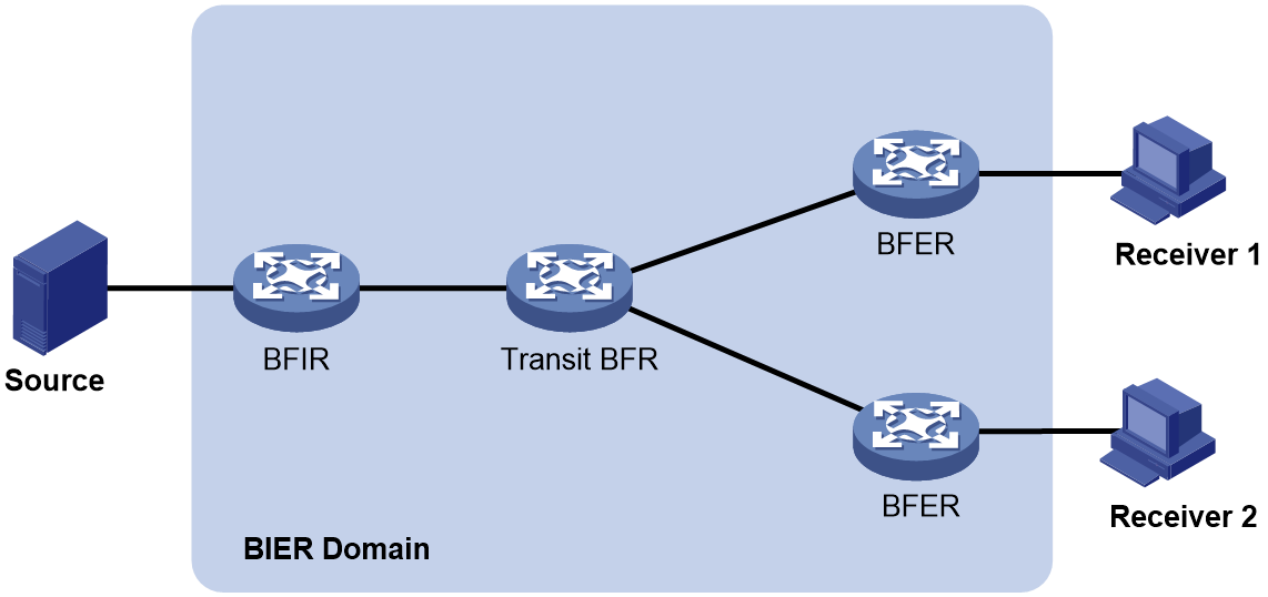
A router that supports BIER is known as a Bit-Forwarding Router (BFR).. As shown in Figure 1, a BIER network consists of the following BFRs:
· Bit Forwarding Ingress Router (BFIR)—A multicast data packet enters a BIER domain at a BFIR. A BFIR encapsulates the multicast data packet as a BFIR packet.
· Transit BFR—A transit BFR receives a multicast data packet from one BFR to another BFR in the same BIER domain.
· Bit Forwarding Egress Router (BFER)—A multicast data packet leaves a BIER domain at a BFER. A BFER decapsulates the multicast data packet and sends it to multicast receivers.
BFIRs and BFERs are collectively referred to as BIER edge devices.
Figure 1 BIER network structure
Concepts
· BIER domain and BIER subdomain: A collection of all BFRs within a routing domain (RD) OR an administrative domain (AD) is called a BIER domain. A BIER domain can be divided into one or more BIER subdomains, which can be abbreviated as SD. Each BIER subdomain is identified by a unique Sub-domain ID.
· BFR ID: Used to uniquely identify a BIER edge device within a BIER sub-domain. Transit BFRs do not require a BFR ID configuration.
· BFR prefix: This equates to the Router ID in the routing protocol, used to identify the BFR. In the same BIER subdomain, each BFR must be configured with a unique BFR prefix, and this prefix must be reachable within the intra-domain routing of the BIER subdomain. Currently, the BFR prefix only supports being configured as the Loopback port's address.
· BS (Bit String): BIER uses a specific length of BS to represent the target edge device for BIER messages. Starting from the far right of the Bit String, each bit corresponds to a BFR ID. A bit at position 1 signifies that the edge device identified by its corresponding BFR ID serves as the target edge device for forwarding multicast packets.
· Bit String Length (BSL) refers to the length of the bit string in the BIER encapsulation.
· SI (Set Identifier): When the BSL (BitString Length) in a BIER sub-domain is insufficient to represent the maximum BFR ID, the Bit String is divided into different sets. Each set is identified by an SI. For example, if the maximum BFR ID in a BIER sub-domain is 1024 and the BSL is set to 256, the sub-domain must be divided into four sets: SI 0, SI 1, SI 2, and SI 3.
· BIRT (Bit Index Routing Table): It refers to the BIER routing table entries generated on BFR by combining BIER properties information (Sub-domain ID, BSL, BFR ID) and IGP/BGP routing information as per IGP/BGP protocols. It's used to guide the forwarding of BIER messages.
· F-BM (Forwarding-Bit Mask): Represents the collection of BIER subdomain margin nodes that can be reached when the BFR duplicates and transmits multicast packets to the next hop neighbor. F-BM is obtained by the BFR passing 'OR' operations on the Bit String of all BIER subdomain margin nodes that the neighbor can reach.
· In the BIER subdomain, multicast traffic is forwarded hop-by-hop by querying the Bit Index Forwarding Table (BIFT). Each BIFT is determined by a tuple (BSL, SD, SI). BIFT is generated by the BFR consolidating entries in the BIRT with the same neighbor but different entries, with each entry recording a next-hop neighbor and its corresponding F-BM.
Layering
As specified in RFC 8279, the BIER architecture consists of three layers: routing underlay, BIER layer, and multicast flow overlay.
Routing underlay
The Underlay layer, functioning as a traditional IP routing layer, carries BIER property information of BFR via the expansion of TLV properties in the IGP protocol (currently only supports IS-IS) and floods it within the BIER subdomain. The BFR generates routes to other BFR prefixes within its subdomain based on the IGP algorithm, that is, to each BFR route, thereby establishing neighborhood between nodes within the BIER subdomain and the optimal forwarding paths between nodes.
BIER layer
The BIER layer, as the core of BIER forwarding, extends the IGP protocol on the control plane. This is to create the BIFT, which guides multicast message forwarding within the BIER domain. The BIFT generation process is as follows:
1. BFRs announce BIER configuration information through the IGP protocol.
2. The BIER information announced by BFR based on the IGP protocol generates BIFT on the optimal forwarding path between BFRs.
In the forwarding plane, BFRs use the information in the BIER header to find BIFT entries and replicate and forward the multicast messages with BIER headers.
Multicast flow overlay
The Overlay Layer mainly handles multicast service control information exchange on the control plane, such as join and leave messages for user multicast between BFIR and BFER, and establishes multicast forwarding table entries corresponding to BFERs.
On the forwarding plane, when a multicast message reaches BFIR, it determines the destination BFER set and encapsulates the corresponding BIER header; when a multicast message with a BIER header arrives at a BFER node, it decapsulates the BIER header and completes the subsequent multicast message forwarding.
Packets encapsulation
Message encapsulation format
The user's multicast packet enters the BIER network and is encapsulated by a BIER message header at the entrance node. The multicast packet leaves the BIER network, and at the exit node, the BIER message header is decapsulated to restore the multicast packet. The BIER message header is situated between the inner multicast packet and the outer Underlay encapsulation (such as MPLS, IPv6 header, etc.), and its encapsulation format is defined by RFC8296 as shown in Figure 2.
Figure 2 The encapsulation format of BIER header.
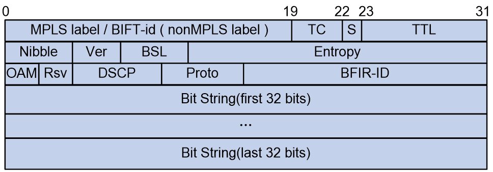
The meanings of each field in the BIER header are as follows:
· MPLS label/BIFT-id:
¡ When the underlay stratum is MPLS, it refers to the MPLS label.
¡ When the Underlay layer uses other protocols, it denotes the BIFT-ID used to identify BIFT. The BIFT-ID is uniquely determined by the triplet (BSL, SD, SI).
· TC, or Traffic Class, is a 3-bit ranking system used for Quality of Service (QoS). It manages the rank of traffic flow.
· S: 1 bit, indicating the bottom of the label stack, similar to the S bit in MPLS encapsulation. For specific usage, refer to RFC3032.
· TTL: 8 bits, used as TTL during MPLS encapsulation. For specific usage, refer to RFC3032.
· Nibble: 4 bits, with a valid value of 0101. If a BFR receives a BIER message with this field not set to 0101, it discards the message.
· Ver: 4 bits, indicating the version number. The current value of 0 means it's an experimental version.
· BSL: 4 bits, values from 1 to 7 represent different bit string lengths, with the following correspondences:
¡ 1: Indicates a bit string length of 64 bits.
¡ 2: Indicates a bit string length of 128 bits.
¡ 3: Indicates a bit string length of 256 bits.
¡ 4: Indicates a bit string length of 512 bits.
¡ 5: Indicates a bit string length of 1024 bits.
¡ 6: Indicates a bit string length of 2048 bits.
¡ 7: Indicates a bit string length of 4096 bits.
· Entropy: 20 bits, used to select paths when equivalent paths exist. Messages with the same Bit String and Entropy value choose the same path.
· OAM: 2 bits, default is 0, can be used for OAM function, without affecting forwarding and QoS.
· Rsv: 2 bits, reserved bits, defaulting to 0.
· DSCP: 6bits, it determines the priority level of the packet itself, which sets the priority level for packet transmission.
· Source Text: Proto: 6bits, the type of Payload message follows immediately after the BIER header.
· BFIR-ID: 16bits, it is the BFR ID where the multicast packet enters the BIER domain.
· BitString: a bit string, where each bit corresponds to a BFR ID of a BFER. If a bit is set to 1, it indicates that the packet needs to be forwarded to the corresponding BFER.
Supported message encapsulation types
In RFC8279, several encapsulation types for BIER are defined, each with a different format. Currently, our company supports G-BIER (Generalized BIER, generic bit index explicit replication) and BIERv6 (Bit Index Explicit Replication IPv6 Encapsulation, IPv6 encapsulated bit index explicit replication) encapsulation types.
· G-BIER is a general BIER encapsulation scheme proposed by China Mobile, which adapts the BIER header to the characteristics of the IPv6 network, thereby achieving better consolidation with IPv6. For a detailed introduction to G-BIER message encapsulation, see G-BIER message format.
· BIERv6 is a new multicast solution based on Native IPv6, combining the advantages of IPv6 and BIER. It integrates seamlessly into SRv6 networks and simplifies protocol complexity. For a detailed introduction to BIERv6 message encapsulation, see BIERv6 message format.
BIER control plane
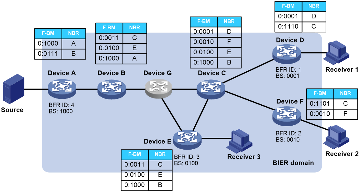
BIER information configured on BFRs (SD, BFR prefix, BFR ID, etc.) is flooded throughout the BIER domain via the IGP protocol. IGP calculates the BIER shortest-path tree (with BFIR as the root and Transit BFRs and BFERs as leaves) based on the flooded BIER information from neighbors. BFRs generate BIRT based on the BIER shortest-path tree, which ultimately leads to the creation of BIFT to guide BIER forwarding.
As shown in Figure 3, the BIER domain includes nodes (Device G) that support BIER and those that do not. For nodes that do not support BIER, all their child nodes are added as leaf nodes to the BIER shortest path tree (SPT). If the child nodes do not support BIER, the iteration continues down to the child nodes that do. For instance, Device G does not support BIER. Device G passes the BIER information of its child nodes, Device C and Device E, to Device B, which generates next hop neighbor information entry in the BIFT for the non-directly connected neighbors Device C and Device E.
Figure 3 BIER Control Plane BIFT
BIER forwarding process
When a multicast packet arrives at the BFIR
node, the BFIR looks up the multicast forwarding table and gets the
corresponding BIFT-ID and BS from the multicast entry, with BS representing the
complete set of BFERs that the multicast packet reaches after traversing the
BIER domain. The BFIR matches the specified BIFT based on the BIFT-ID, and
replicates and forwards the packet after matching and calculating according to
the Bit String carried in the packet header and the BIFT entry. Once the BIER
packet reaches the BFER node, it is decapsulated into a multicast packet, and
forwarded based on the multicast address found in the multicast forwarding
table.
In the BIER forwarding process, when it needs to pass non-BIER nodes, that is,
the next hop neighbor of the BFR is not a direct neighbor, specific technical
methods can be used to traverse non-BIER nodes. The specific technical method
depends on the outer encapsulation of the BIER encapsulation (for example, MPLS
encapsulation relies on LSP to pass through non-BIER nodes, and IPv6
encapsulation can route to non-direct BIER neighbors according to ordinary IPv6
unicast routing).
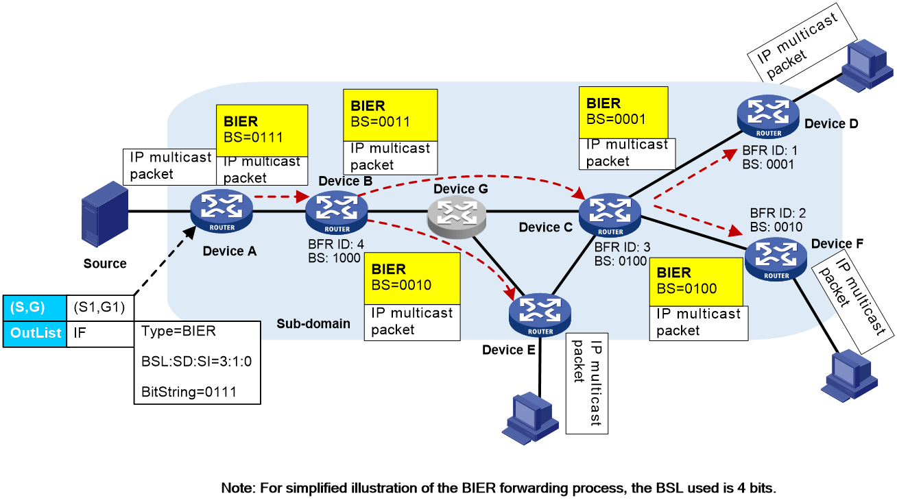
Let's illustrate the BIER forwarding process with a specific example. As shown in Figure 4, every device in the BIER subdomain generates a BIFT based on the IGP protocol. Receivers of a certain multicast group are downstream of Device D and Device E. Device A, acting as a BFIR, collects the MVPN information from Device D and E that are in the same BIER subdomain as Device A via the BGP MVPN route. When Device A receives a multicast packet destined for the multicast group, the BIER forwarding process is as follows:
1. After Device A receives an IP multicast message, it looks up the multicast forwarding table entry to obtain the corresponding BIFT-ID and BS. Using the BIFT-ID, it finds the relevant BIFT table. Device A then performs a "bitwise AND" operation between the BS and each F-BM entry in the BIFT table. It copies the multicast message and encapsulates it according to the BIER message format (encapsulating the BS value obtained after the "bitwise AND" calculation) and sends it to the next-hop neighbor, Device B.
2. After receiving the BIER packet, Device B, based on the BIFT-ID and BS in the BIER header, executes the same steps as in Step 1. It discovers that the next hop neighbors are Device C and Device E, which need to pass through non-BIER node Device G. At this point, specific technical methods can be used to traverse the non-BIER nodes, replicate the multicast packet, encapsulate it according to the BIER packet format, and send it to Device C and Device E.
3. Upon receiving the BIER message, Device C performs the same operation as in step 1. It duplicates the multicast packet and after encapsulating it in the BIER message format, sends it to Device D and Device F.
4. After receiving the BIER message, Device D, Device E, and Device F discover that only the F-BM corresponding to this node is not 0 after performing the "bitwise and" operation with the BS in the upstream BIER message, indicating that this node is a BFER and needs to stop BIER forwarding. At that time, Device D, Device E, and Device F respectively decapsulate the multicast packet from the BIER header, and continue to transmit it to the downstream receiver according to the multicast route table entry.
Figure 4 BIER message forwarding process diagram
IS-IS BIER expansion
BIER information, including BFR prefix, Sub-domain, and BFR ID, is disseminated via IS-IS BIER extensions within the BIER sub-domain. Nodes receiving BIER information generate a corresponding BIFT if they support BIER forwarding. If they do not support BIER forwarding, IS-IS does not recognize the BIER information and floods it directly.
RFC8401 defines the release mechanism for BIER information, specifically, it is achieved by carrying a BIER Info Sub-TLV in the IS-IS Reachability Prefix TLV (TLV 236 defined in RFC5308 and TLV 237 defined in RFC5120).
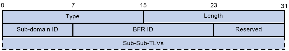
The format of the BIER Info Sub-TLV is shown in Figure 5.
Figure 5 BIER Info Sub-TLV is a sub-type length value in BIER information.
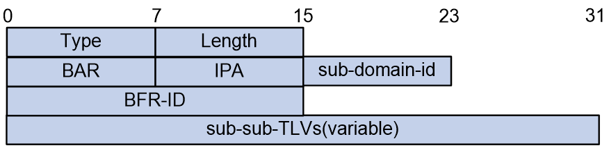
The meanings of each field in the BIER Info Sub-TLV are as follows:
· Type: 8 bits, the type of Sub-TLV, with a value of 32, representing the BIER Info Sub-TLV.
· The BIER Info Sub-TLV length is 8 bits.
· BAR: 8 bits, the BIER algorithm is used to calculate the path to BFER.
· IPA: 8 bits, IGP algorithm, indicates an enhanced or improved IGP algorithm, which can replace the BAR algorithm.
· Sub-domain-id: 8 bits, the ID of a BIER sub-domain.
· BFR-ID: 16 bits, used to uniquely identify a BIER edge device within a BIER sub-domain.
· Sub-sub-TLVs (variable): Variable length, representing different types of BIER encapsulation (such as MPLS, G-BIER, BIERv6 encapsulation, etc.).
G-BIER technology implementation
G-BIER (Generalized Bit Index Explicit Replication) is a universal BIER encapsulation approach proposed by China Mobile together with manufacturers such as H3C, Huawei, and ZTE. It modifies the standard BIER header defined by the RFC to better align with the features of IPv6 networks, thus enhancing integration with IPv6.
G-BIER message format
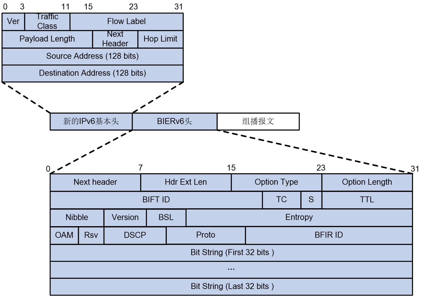
The encapsulation of G-BIER messages is achieved by adding a new IPv6 basic header and BIER header before the multicast datagram. As shown in Figure 6, the Next Header value in the IPv6 basic header is 60, indicating that the next message header is DOH (Destination Options Header).
For G-BIER messages, the following conventions are in the basic IPv6 header:
· Source Address: The source address must be configured as the multicast service source address of the BFIR, generated by combining the BFIR's prefix address and the multicast service ID value. The prefix address identifies the network location of the BFIR, while the multicast service ID distinguishes different MVPN instances. During the forwarding of multicast packets, this source address remains unchanged.
· Destination Address: The destination address needs to be configured as a Multicast Policy Reserved Address (MPRA) specifically for BIER forwarding. This address must be reachable via intra-domain routing within the subdomain. When the BFR receives an IPv6 message with a destination address configured as the local MPRA, it indicates that the message needs to be forwarded via G-BIER.
Figure 6 G-BIER packet encapsulation diagram
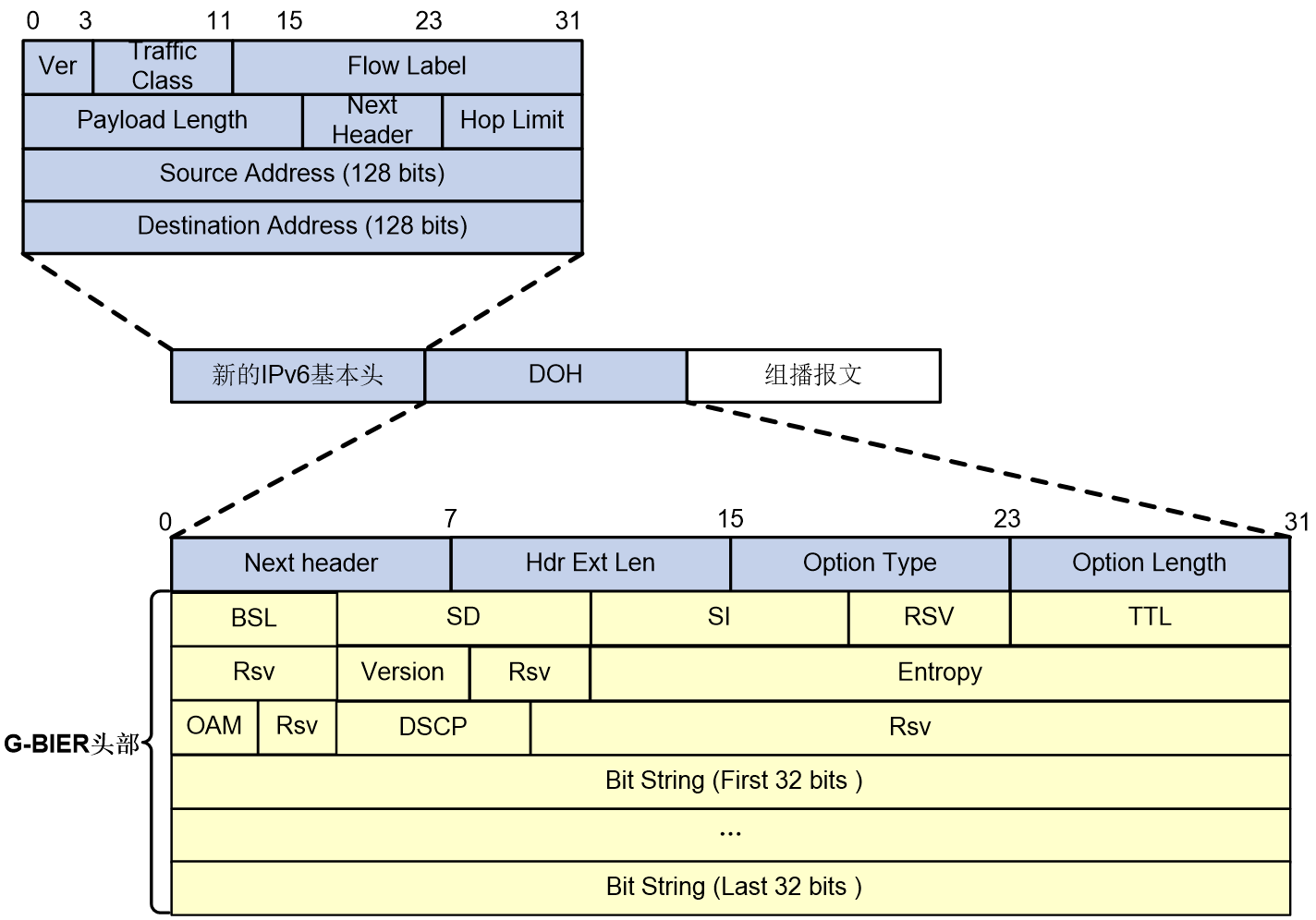
In G-BIER messages, the BIER header mainly consists of the following parts:
· Next Header: 8 bits, used to identify the type of the next message header.
· Source Text: /nHdr Ext Len: 8bits, indicates the length of the IPv6 extension header.
· Option Type: 8bits, the option type is G-BIER.
· Option Length: 8 bits, indicating the length of the option.
· BSL: 4 bits, values from 1 to 7 represent different bit string lengths as follows:
¡ 1: Indicates a bit string length of 64 bits.
¡ 2: Indicates a bit string length of 128 bits.
¡ 3: Indicates a bit string length of 256 bits.
¡ 4: Indicates a bit string length of 512 bits.
¡ 5: Indicates a bit string length of 1024 bits.
¡ 6: Indicates a bit string length of 2048 bits.
¡ 7: Indicates a bit string length of 4096 bits.
· SD: 8 bits, BIER sub-domain ID.
· SI: 8bits, set as an identifier.
· Rsv: Reserved field.
· TTL: 8 bits, same as the TTL in IP packets, used to prevent loops.
· Version: 4 bits, version number, currently only supports 0.
· Entropy: 20 bits, used to select paths when equivalent paths exist. Packets with the same Bit String and Entropy values choose the same path.
· OAM: 4 bits, default value is 0, can be used for OAM functions.
· DSCP: 7 bits, the packet's own priority level, determines the priority of packet transmission.
· Bit String: A sequence of bits.
G-BIE R forwarding process
The forwarding process of G-BIER is similar to BIER. Please refer to "BIER forwarding process".
Control Plane of G-BIER
Inter-AS G-BIER control plane
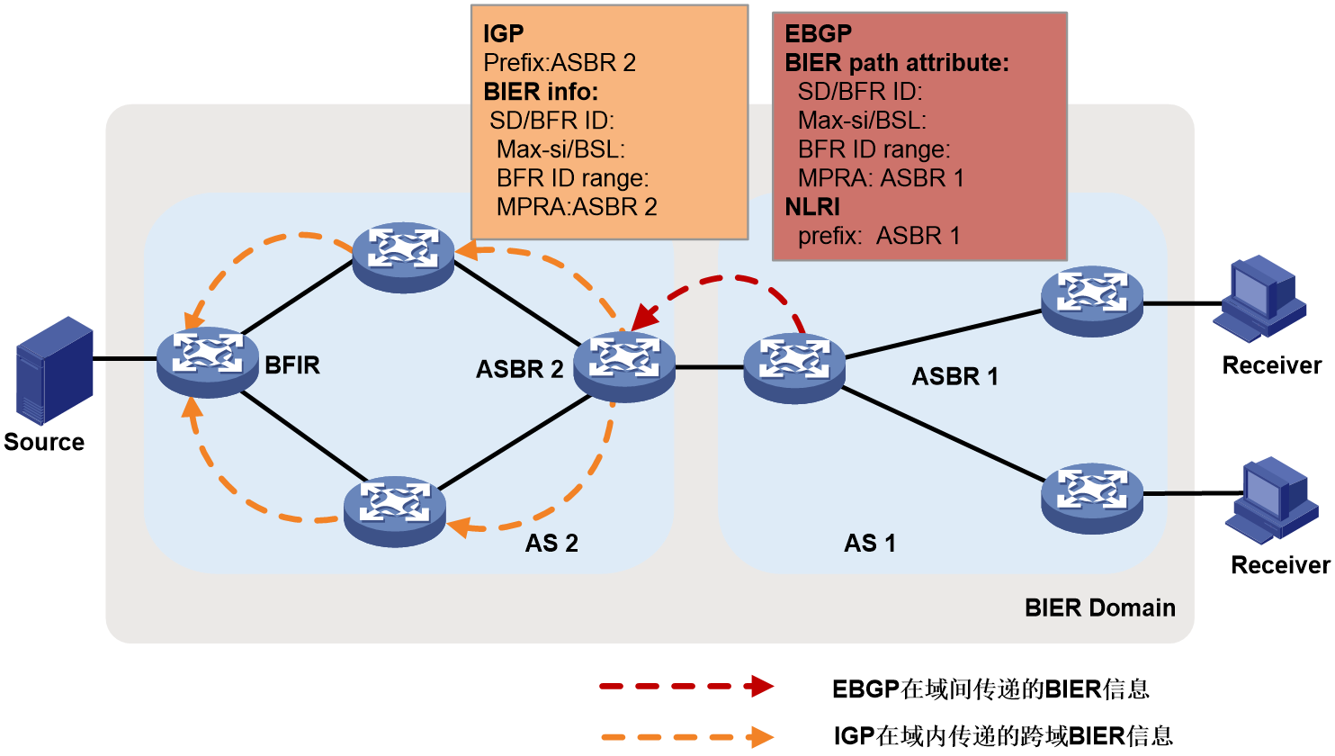
As shown in Figure 7, in scenarios where multicast services are deployed across Autonomous Systems (AS), all routers within the domains involved must join the same BIER sub-domain. ASBR 1 in AS 1 advertises the BFR IDs within AS 1 to AS 2 via the EBGP protocol, enabling nodes in AS 2 to establish BIRT and BIFT for reaching BFERs corresponding to BFR IDs in AS 1.
Taking the establishment of EBGP neighbors between ASBRs as an example, ASBR 1 publishes its BIER information (such as SD, BSL, Max-SI, MPRA) to its cross-domain BGP neighbor, ASBR 2, using unicast host routes. ASBR 2 then sets up BIRT and BIFT to reach each BFER within AS 1.
ASBR 2 further disseminates AS 1's BIER information within AS 2 using the following two methods:
· ASBR 2 imports the BIER information carried by EBGP into IGP.
ASBR 2 floods the EBGP routes into IGP, spreading BIER information across AS 2 and creating cross-domain BIRT and BIFT. G-BIER also expands IS-IS BIER to include the range of cross-domain introduced BFR IDs, in addition to the originally supported Sub-domain, BSL, and MPRA.
Figure 7 Announce (Annc) BIER information (Info) across AS using IGP method.
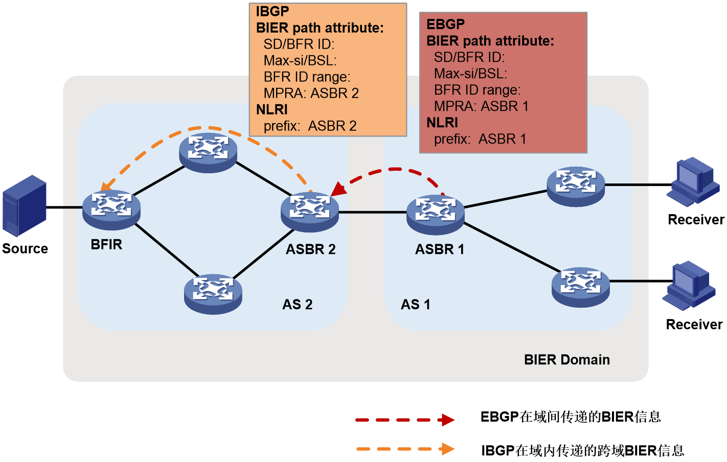
· ASBR 2 uses IBGP to distribute the BIER information carried by EBGP only to the BFIRs within AS 2.
ASBR 2 passes the BIER information back to BFIR through the routing policy, with the BFR prefix being the host routing prefix of the ASBR 2 node, and the next hop being the IPv6 address of the ASBR 2 node. The BIER information carried in the route includes ASBR 2's SD, BSL, MPRA and the range of BFR IDs in AS 1 that can be reached through ASBR 2. After receiving the route carrying BIER information from ASBR 2, BFIR establishes BIRT and BIFT to each BFR ID within AS 1.
Figure 8 Cross-AS BIER information announcement (via IBGP)
IS-IS G-BIER expansion
RFC 8401 defines the mechanism for publishing BIER Sub-domain information, specifically see "IS-IS BIER expansion." IS-IS G-BIER extends the BIER Info Sub-TLV by adding the following three sub-sub-TLVs:
1. The sub-sub-TLV capability of G-BIER.
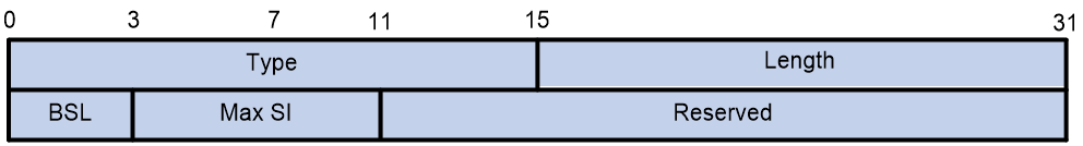
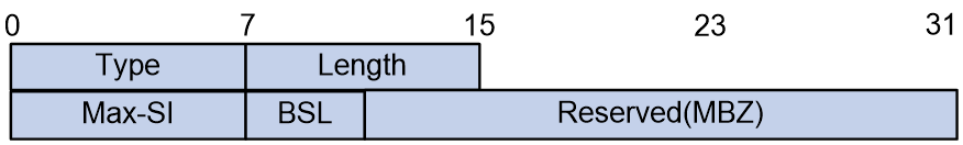
The node's G-BIER capability is released by passing the G-BIER ability through the newly added G-BIER sub-sub-TLV in the BIER Info Sub-TLV. The specific format of the sub-sub-TLV is shown in the Figure 9.
Figure 9 The G-BIER capability sub-sub-TLV.
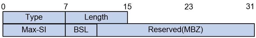
The meaning of each field in the G-BIER sub-sub-TLV is as follows:
¡ The Type is 8bits, which is a subtype of the sub-sub-TLV. Its value is 6, indicating a sub-sub-TLV with G-BIER capability.
¡ The length is 8 bits, which represents the length of the TLV.
¡ Max-SI: 8 bits, the maximum value of the set identifier.
¡ BSL: 4 bits, bit string length.
¡ Reserved: 20 bits, a reserved field for byte alignment.
2. G-BIER MPRA Mesh Point sub-sub-TLV.
G-BIER requires configuring a multicast policy reserved address (MPRA) on BFRs for BIER forwarding. This MPRA is advertised through IS-IS to inform neighbors to use this IPv6 address as the destination when sending G-BIER packets to the node.
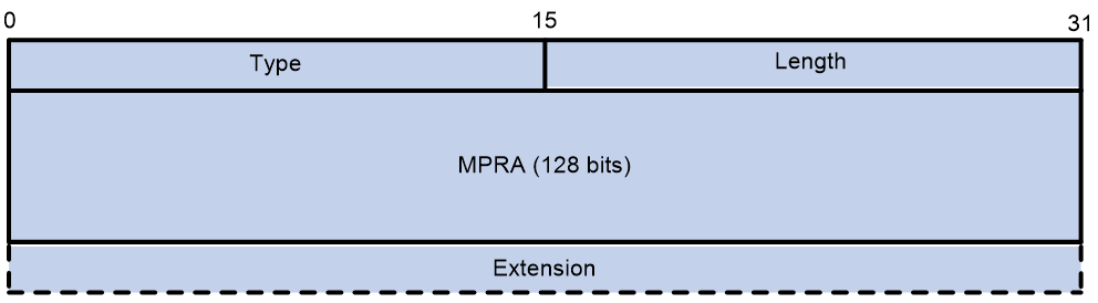
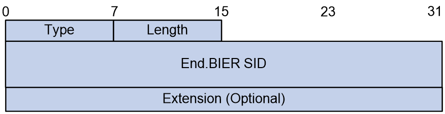
As part of G-BIER encapsulation, the MPRA is announced by adding a G-BIER MPRA sub-sub-TLV within the BIER Info sub-TLV. The format of this sub-sub-TLV is shown in Figure 10.
Figure 10 G-BIER MPRA sub-sub-TLV
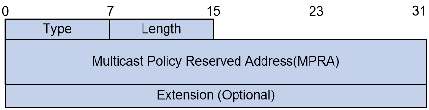
The meanings of the fields in the G-BIER MPRA sub-sub-TLV are as follows:
¡ The type is 8 bits, and the sub-sub-TLV type is 7, which indicates the G-BIER MPRA sub-sub-TLV.
¡ Length: 8 bits, indicating the length of the TLV.
¡ MPRA: 128 bits, multicast policy reserved address.
¡ Extension: The specific format and meaning are not defined at this time and are not processed.
3. G-BIER BFR-ids sub-sub-TLV
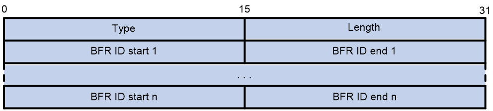
In the scenario of Inter-AS G-BIER, IS-IS introduces the BIER information carried by EBGP. At the same time, it passes the reachable BFR ID range introduced by ASBR through the newly added BFR-ids sub-sub-TLV. The format of this sub-sub-TLV is shown as Figure 11.
Figure 11 G-BIER BFR-ids sub-sub-TLV
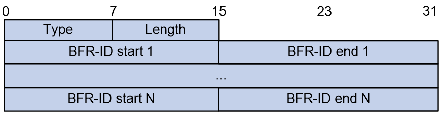
The meanings of the fields in the G-BIER BFR-ids sub-sub-TLV are as follows:
¡ Type: 8bits, denotes the type of sub-sub-TLV. The value is 8, indicating it as G-BIER BFR-ids sub-sub-TLV.
¡ Length: 8 bits, representing the TLV length.
¡ BFR-ID start: The 16-bit starting value for the range of BFR IDs that can be reached across domains.
¡ The maximum value of the range of BFR ID that can be reached across domains is 16 bits.
BGP G-BIER expansion
G-BIER path attribute
In Inter-AS G-BIER scenarios, network nodes encapsulate G-BIER information within BGP Update messages. The G-BIER information carried in BGP messages is divided into two parts:
· BFR Prefix: Encapsulated in the NLRI field of the Update message.
· G-BIER Path Attribute: A newly defined routing attribute that contains information such as the G-BIER sub-domain, BFR ID, BSL, and MPRA.
Figure 12 G-BIER path attribute
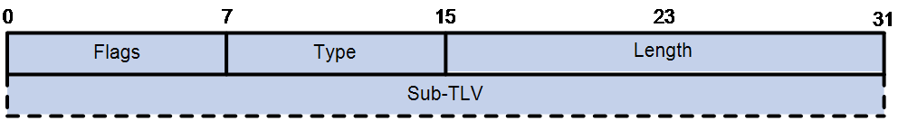
As shown in Figure 12, the G-BIER path attribute that BGP adds to G-BIER includes the following fields:
· Flags: BGP attribute flags with a value of 0xd0, indicating that the attribute is an optional transitive attribute with complete information.
· Type: The type of the path attribute, with a value of 67.
· The length of the path attribute is measured in bytes.
· The Sub-TLV is a variable length path attribute which carries the G-BIER information.
G-BIER Sub-TLV
The format of the G-BIER path attribute's Sub-TLV (G-BIER Sub-TLV) is shown in Figure 13.
Figure 13 G-BIER Sub-TLV format
The meaning of each field in the G-BIER Sub-TLV is as follows:
· Type: The type of Sub-TLV, with a value of 1, indicating a Sub-TLV with G-BIER capabilities.
· Length: The length of the Sub-TLV, measured in bytes.
· Sub Domain: G-BIER subdomain ID.
· BFR ID: The BFR ID of the G-BFER that advertises the route.
· Reserved: This is a reserved field used for byte alignment.
· Sub-Sub-TLVs (Optional): The child TLVs carried by the Sub-TLV, with variable length.
G-BIER Sub-Sub-TLV
The three types of G-BIER Sub-Sub-TLVs currently supported are: BSL Sub-Sub-TLV, MPRA Sub-Sub-TLV, and BFR ID range Sub-Sub-TLV.
1. BSL Sub-Sub-TLV
The BSL Sub-Sub-TLV is used to announce the BSL and Max SI that a node supports, as shown in the format depicted in Figure 14.
Figure 14 BSL Sub-Sub-TLV format
The meaning of each field in the BSL Sub-Sub-TLV is as follows:
· Type: The type of Sub-Sub-TLV, with a value of 1.}
· Length: The length of the Sub-Sub-TLV, with a value of 4, in bytes.
· BSL: Bit String Length.
· Max SI: The maximum value for the identifier set.
· Reserved: A reserved field used for byte alignment.
2. MPRA Sub-Sub-TLV
The MPRA Sub-Sub-TLV is used to announce a node's multicast policy reserved address, with the format shown in Figure 15.
Figure 15 The format of the MPRA Sub-Sub-TLV.
The meanings of the fields in the MPRA Sub-Sub-TLV are as follows:
· The type of the Sub-Sub-TLV is set to 2.
· Length: The length of the Sub-Sub-TLV, with a value greater than 16, in bytes.
· MPRA (Mesh Point Reserved Address) refers to a multicast policy with a reserved address, featuring a length of 128 bits.
· Extension: Expansion field with variable length. The specific format and meaning of this field are not defined yet.
3. The range of BFR-ID is represented by the Sub-Sub-TLV.
The BFR-ID range Sub-Sub-TLV is used to announce the known BFR ID range within this AS, as shown in the format of Figure 16.
Figure 16 BFR-ID Range Sub-Sub-TLV
The meanings of each field in the BFR-ID range Sub-Sub-TLV are as follows:
· Type: The type of the Sub-Sub-TLV.
· Length: The length of the Sub-Sub-TLV, which is an integer multiple of 4, measured in bytes.
· Start of BFR ID range: This is the initial value of the BFR ID range.
· End of BFR ID range: The maximum value of the BFR ID range.
NG MVPN over G-BIER
NG MVPN over G-BIER control plane
In the NG MVPN over G-BIER scenario, G-BIER is used to establish a carrying tunnel. Multicast private network traffic is encapsulated by G-BIER and sent across the public network to other nodes in the BIER sub-domain.
The control plane package of NG MVPN over G-BIER includes the following unique technical implementations:
· Receiver PE collects information.
In this scenario, the multicast source-side PE first recognizes which receiver-side PEs the multicast traffic needs to be transmitted to. Then, the source-side PE encapsulates the Bit String based on the received private network multicast traffic. In this, the gathering mechanism of each PE member within MVPN is similar to the process under RSVP-TE and mLDP modes in MVPN.
· Added a new BIER tunnel type attribute.
To support NG MVPN over G-BIER, RFC8556 defines the information required when using BIER tunnels in BGP MVPN services, namely, a BIER-type PTA (PMSI Tunnel attribute). This BIER-type PTA is used when G-BIER tunnels are employed in BGP MVPN services. Originally, the MPLS Label field of the PTA was used to identify the upstream allocation tags of the MVPN instance. In the MVPN based on G-BIER tunnels, this field is no longer used. Instead, a new BGP property carrying the IPv6 source address (multicast service source address) used to identify the MVPN instance is used, which is referred to as the MSID (Multicast Service Identifier). Correspondingly, the value of the MPLS Label field in the PTA is set to 0.
MVPN BGP Protocol Expansion
MSID Attributes
In MVPN over G-BIER, the newly added BGP property MSID is used to identify the MVPN-instance. The multicast source address within MSID is carried by the multicast source-side PE in the class 1 route 'Intra-AS I-PMSI A-D route', and is announced to the recipient-side PE. The recipient-side PE records the corresponding relationship between this source address and the MVPN-instance. When the recipient-side PE receives a multicast packet encapsulated in G-BIER, it will use the multicast source address in the packet to find the corresponding MVPN-instance, find the corresponding entry in the multicast forwarding table of the MVPN instance, and forward the multicast packet.
The BGP MSID properties and their content adhere to the format requirements defined by BGP properties, shown as Figure 17.
Figure 17 MSID Attribute Format
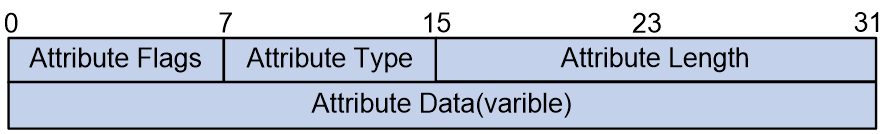
The meaning of each field in the MSID Attribute is as follows:
· Attribute Flags: 8 bits, identify (ID) properties.
· Attribute Type: 8bits, representing the category field of the attribute, named as MSID.
· Attribute Length: 16 bits, indicating the length of the attribute.
· Attribute Data: Variable length, representing the attribute data, expressed using a Sub-TLV with no fixed fields.
The Attribute Data is a Sub-TLV with no fixed fields, and its specific format is shown in Figure 18.
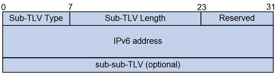
The meanings of each field in the Sub-TLV are as follows:
· Sub-TLV Type: 8 bits, indicating the type of the Sub-TLV.
· Sub-TLV Length: A 16-bit value representing the length of the Sub-TLV.
· Reserved: 8 bits, reserved field.
· IPv6 address: The source IPv6 address.
· sub-sub-TLV: Variable length, indicating the sub-sub-TLVs carried by this Sub-TLV, currently only supporting the Structure sub-sub-TLV.
The format of the Structure sub-sub-TLV is shown as in Figure 19.
Figure 19 Structure sub-sub-TLV format
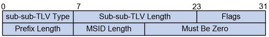
The meanings of each field in the Structure sub-sub-TLV are as follows:
· sub-sub-TLV Type: 8 bits, the type of sub-sub-TLV, with a value of 1 indicating a Structure sub-sub-TLV.
· sub-sub-TLV Length: 16 bits, the length of the sub-sub-TLV, with a value of 5.
· Flags: 8 bits, a flag field for future expansion, currently required to be 0.
· Prefix Length: 8 bits, indicating the length of the prefix.
· The length of the multicast service ID, known as MSID Length, is 8 bits.
· Must Be Zero: 16bits, reserved field.
MVPN Extended Community Attribute
1. Introduction to MVPN Extended Community Attributes
The extended community attributes of MVPN are mainly used for the release and reception of C-multicast routes, including the following two types:
· The Source AS Extended Community property is used to identify the AS number where the multicast source is located, applicable in cross-domain scenarios.
· VRF Route Import Extended Community: This property is used to identify the IP address of the multicast source side PE and the VPN-instance where the multicast source is located.
The format of Source AS Extended Community and VRF Route Import Extended Community in the extended community attribute is shown in Figures 20 and 21, respectively.
Figure 20 The format of the Source AS Extended Community is as follows.
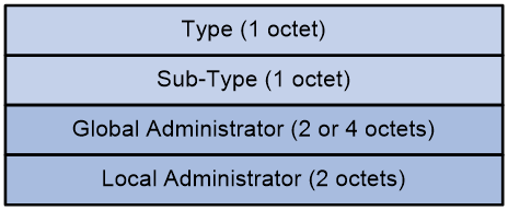
The Source AS Extended Community includes the following fields:
· Type: The type of the extended community attribute, which can be either 0x00 (representing the 2-byte AS number type of extended community attribute) or 0x02 (representing the 4-byte AS number type of extended community attribute).
· Sub-Type: It's a subtype of the extended community attribute, with a value of 0x09, signifying that this extended community attribute is a Source AS Extended Community.
· Global Administrator: The Autonomous System (AS) number where the multicast source is located can be in the form of a 2-byte AS number or a 4-byte AS number.
· Local Administrator: The value is 0, with no special meaning currently.
Figure 21 Format of the VRF Route Import Extended Community.

The VRF Route Import Extended Community includes the following field:
· Type: The type of the extended community attribute, with a value of 0x01 (indicating an IPv4 address type extended community attribute) or no value (indicating an IPv6 address type extended community attribute).
· Sub-Type: The sub-type of the extended community attribute, with values being 0x0b (for IPv4 class of address type extended community attribute) OR 0x000b (for IPv6 class of address type extended community attribute), indicating that the extended community attribute is a VRF Route Import Extended Community.
· IP address of the multicast source-side PE in IPv4/IPv6.
· Local Administrator: The VPN-instance where the multicast source is located.
2. The working mechanism of the MVPN extended community attribute.
As illustrated in Figure 22, both PE 1 and PE 2 serve as multicast source PEs, while PE 3 regards as the receiver-side PE. Both PE 1 and PE 2 associate with site of VPN 1 and the public network instance. The VRF Route Import Extended Community value of VPN 1 on PE 1 is 1.1.1.1:1; the VRF Route Import Extended Community value of the public network instance on PE 1 is 1.1.1.1:0 (the value of Local Administrator in the VRF Route Import Extended Community of the public network instance must be 0). The value of Source AS Extended Community on PE 1 is 10:0. The VRF Route Import Extended Community value of VPN 1 on PE 2 is 2.2.2.2:1; the VRF Route Import Extended Community value of the public network instance on PE 2 is 2.2.2.2:0 (the value of Local Administrator in the VRF Route Import Extended Community of the public network instance must be 0); the value of Source AS Extended Community on PE 1 is 10:0.
Figure 22 Extended community attribute work mechanism of nMVPN
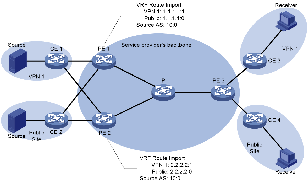
After establishing a BGP session for the BGP MVPN address family with PE 3, both PE 1 and PE 2 will release unicast route information to the multicast source to PE 3. Herein, the unicast route information for the multicast source of the VPN-instance is carried through BGP VPNv4 OR VPNv6 routes, and the unicast route information for the multicast source of the public network instance is carried through BGP IPv4/IPv6 unicast or BGP IPv4/IPv6 multicast routes. All announced BGP routes carrying unicast route information to the multicast source will carry both Source AS Extended Community and VRF Route Import Extended Community.
Upon receiving the BGP route information of the unicast route to the multicast source from PE 3, the BGP route is given priority. Afterwards, the Source AS Extended Community and VRF Route Import Extended Community that come with the route are stored for the construction of the C-multicast route in the future. In this instance, it is assumed that PE 3 has given priority to the BGP route information of the unicast route to the VPN 1 multicast source from PE 1, and the BGP route information of the unicast route to the multicast source of the public network instance from PE 2.
The construction process of C-multicast route for VPN instance VPN 1 and public network instance is as follows:
· When PE 3 receives a multicast join message from CE 3, it constructs a C-multicast route and transmits it to PE 1 and PE 2. The 'Source AS' field of this route corresponds to the AS number in the received 'Source AS Extended Community'. The 'Route Target' property carried with the route is the 'VRF Route Import Extended Community' from the BGP preferred route, i.e., 1.1.1.1:1.
¡ Upon receiving the C-multicast routing, PE 1 compares the IP address carried in the RT properties of the C-multicast routing and finds it to be 1.1.1.1, which is the local source interface address. Consequently, it receives the C-multicast routing. Immediately after, PE 1 determines that the C-multicast routing belongs to the VPN-instance VPN 1 based on the Local Administrator in the RT properties. It then adds the C-multicast routing to the multicast routing table of VPN 1.
¡ Upon receiving the C-multicast route, PE 2 compares the IP address carried in the RT properties of the C-multicast route, and finds it to be 1.1.1.1, not the local source interface address, so it discards the C-multicast route.
Subsequently, when the multicast source in VPN 1 transmits multicast packets, only PE 1 has formed a multicast entry. The multicast packets are encapsulated by G-BIER at PE 1, and then transmitted to PE 3 through the G-BIER public network tunnel. After decapsulation is performed on PE 3, the packets are forwarded to CE 3.
· When PE 3 receives a multicast join message from CE 4, it constructs a C-multicast route and sends it to PE 1 and PE 2. The Source AS field of this route is the AS number from the received Source AS Extended Community. The route carries the Route Target attribute, which is the VRF Route Import Extended Community of the BGP preferred route, specifically 2.2.2.2:0.
¡ Upon receiving the C-multicast route, PE 2 compares the IP address carried in the RT attribute of the route and identifies it as 2.2.2.2, which is the local source interface address, and accepts the C-multicast route. Then, PE 2 determines that the C-multicast route belongs to a public instance based on the Local Administrator in the RT attribute and adds the C-multicast route to the multicast routing table of the public instance.
¡ After receiving the C-multicast route, PE 1 compares the IP address in the RT attribute of the route, finds it to be 2.2.2.2, which is not the local source interface address, and discards the C-multicast route.
When a multicast source in the public instance sends multicast packets, only PE 2 has formed multicast entries. The packets are encapsulated using G-BIER by PE 2, sent through the G-BIER public tunnel to PE 3, then decapsulated at PE 3 and forwarded to CE 4.
Operation mechanism of NG MVPN over G-BIER
The running mechanism of NG MVPN over G-BIER is as follows:
1. The multicast source-side PE first interacts with the receiver-side PE through BGP MVPN routes to identify which receiver-side PEs need to receive the multicast traffic.
2. The source-side PE and receiver-side PE exchange BIER information (BFR ID, Sub domain ID, BFR prefix) through the Intra-AS I-PMSI A-D Route, S-PMSI A-D Route, and Leaf A-D Route carried in BGP messages.
3. Multicast data is seamlessly transferred from the private to the public network when it travels from the CE to the PE through a compatible tunnel according to the PIM routing table. The source-side PE encapsulates the private network multicast data with a G-BIER header and sends it through the tunnel to the remote PE, which then restores it to a private network multicast message by stripping the label information.
4. When multicast traffic on the multicast source-side PE meets the conditions for selecting a switch-over tunnel, a selective tunnel is established. The private network multicast data encapsulating the G-BIER head is then transmitted through this selective tunnel.
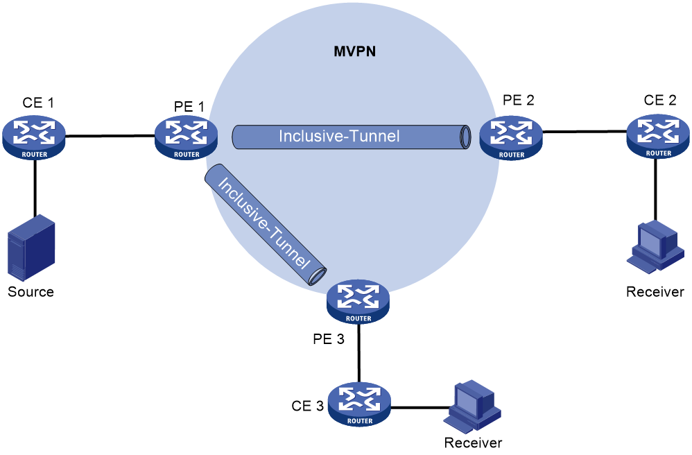
Create a compatibility tunnel.
As shown in Figure 23, the private network side uses the PIM protocol, and the public network is a BIER network. After BGP and MVPN have been deployed on PE 1, PE 2, and PE 3, the process of creating a compatible tunnel is as follows:
1. PE 1 transmits class 1 Intra-AS I-PMSI A-D Route to PE 2 and PE 3, carrying the following information:
¡ Route Target is used to control the release and reception of routes, configured as the Export Target for PE 1.
¡ nPMSI Tunnel attribute: Used for conveying tunnel information. In this, the Tunnel Type field has a value of BIER tunnel, and passes PE 1's BIER information (Sub domain ID, BFR ID, BFR prefix) through the PMSI Tunnel attribute.
2. Upon receiving the Class 1 route transmitted by PE 1, PE 2 and PE 3 check whether the Route Target properties in this route match the Import Target configured in their local VPN-instance. If a match is identified, they receive this route, and transmit a Class 4 route, Leaf A-D route, back to PE 1, which carries the following information:
¡ Route Target is used to control the release and reception of routes, and is configured as the Export Target of either PE 2 or PE 3.
¡ The PMSI Tunnel attribute is used to convey tunnel information. The Tunnel Type field is set to BIER tunnel, and it carries BIER information for PEs in the same BIER subdomain as PE 1 (by using the Sub domain ID obtained from Type 1 routes sent from PE 1 to find the locally configured BFR ID and BFR prefix in the same subdomain).
3. Upon receiving Type 4 routes from PE 2 and PE 3, PE 1 checks if the Route Target attribute in these routes matches the Import Target configured in the local VPN instance. If there is a match, PE 1 accepts the routes and records PE 2 and PE 3 as members of the MVPN. PE 1 then calculates the SI (Set Identifier) based on the BFR ID carried in the received Type 4 routes and the BSL (BitString Length) value configured in the corresponding BIER subdomain. PE 1 merges all the leaf information to create a Bit String for the specified (S, G) pair, forming a BIER type compatibility tunnel.
Figure 23 Creating a compatibility tunnel in the public network.
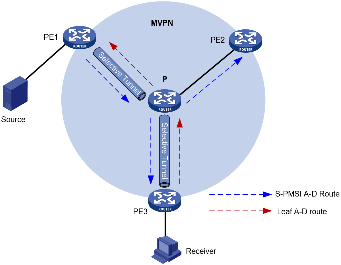
Create a selective tunnel and perform tunnel switching.
When the compatibility tunnel receives multicast traffic for a specified (S, G) entry, if the private network message meets the tunnel switching criteria, a selective tunnel switch occurs, allowing separation of tunnels for different multicast traffic flows. Multiple selective tunnels are allowed within a single VPN instance.
As shown in Figure 24, the specific process of creating a selective tunnel and performing tunnel switchover is as follows:
1. PE 1 transmits class 3 route S-PMSI A-D Route to PE 2 and PE 3, carrying the following information:
¡ Route Target: Controls the advertisement and reception of routes, configured as the Export Target for PE 1.
¡ PMSI Tunnel attribute: Used to convey tunnel information. The Tunnel Type field is set to a BIER tunnel and carries PE 1's BIER information (Sub domain ID, BFR ID, BFR prefix) through the PMSI Tunnel attribute.
2. After PE 2 and PE 3 receive the Type 1 route transmitted by PE 1, they check whether the Route Target property in this route matches the Import Target configured in their local VPN-instance. If it matches, they accept the route. If there are receivers downstream, they reply to PE 1 with a Type 4 Leaf A-D route; otherwise, they discard the route. The replied Type 4 route carries the following information:
¡ Route Target: Used to control the advertisement and reception of routes, configured as the Export Target for PE 2 or PE 3.
¡ PMSI Tunnel attribute: Used for transmitting tunnel information. In which, the 'Tunnel Type' field value is BIER tunnel and is passed through the PMSI Tunnel attribute carrying each BIER info in the same BIER subdomain with PE 1 (obtained from the 'class 1' route sent from PE 1 by looking up the 'Sub domain ID' in the local identical subdomain configured with BFR ID and BFR prefix).
3. After receiving the type 4 routes transmitted from PE 2 and PE 3, PE 1 checks if the Route Target properties in this route match the Import Target configured in the local VPN-instance. If they match, the route is received, and PE 2 and PE 3 are recorded as members of MVPN. Simultaneously, SI is calculated based on the BFR ID carried in the received type 4 routes and the BSL value configured in the corresponding BIER subdomain. By consolidating all leaf information, PE1 generates the Bit String for the specific (S, G), forming the BIER type selective tunnel.
Figure 24 Create a selective tunnel and execute a tunnel switchover.
NG MVPN over G-BIER forwarding process
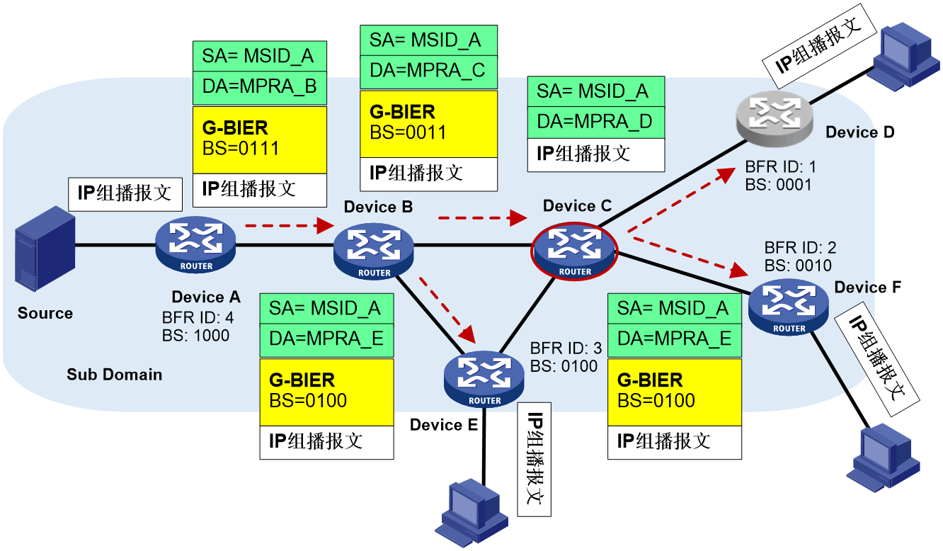
The NG MVPN over G-BIER forwarding process is shown in Figure 25.
Figure 25 The forwarding process of NG MVPN over G-BIER.

1. Device A (Ingress PE node, G-BIER domain BFIR node) receives a multicast packet from VPN-instance CE 1. It then undergoes the following processing steps in sequence:
a. Search for the multicast forwarding table corresponding to the MVPN-instance, determine multicast packet forwarding on the BIER-type PMSI tunnel, and obtain the BIFT ID of BIER PMSI as 0x30100 and Bit String as 0111.
b. Using the BIFT ID and Bit String, the local G-BIER forwarding table is consulted to determine forwarding to the neighboring Device B.
c. The multicast message is copied, and the IPv6 destination address is encapsulated as Device B's MPRA. The BIER encapsulation's BIFT ID is 0x30100, and the Bit String is 0011 (obtained by bitwise AND operation between "0111" and Device B's corresponding F-BM value "0011" in the BIFT).
2. Device B receives the message and matches the destination address of the message with the multicast policy reserved address configured locally. If the match is successful, G-BIER forwarding is executed; otherwise, standard IP forwarding is performed. After a successful match, using BIFT ID=0x30100 and BitString=0011, the local G-BIER forwarding table is checked to determine forwarding to neighbors Device C and Device E. For forwarding to Device E, as an example, the multicast message is copied, and the IPv6 destination address is encapsulated as Device E's MPRA. The BIER encapsulation's BIFT ID is 0x30100, and the Bit String is 0100 (obtained by bitwise AND operation between "0011" and Device E's corresponding F-BM value "0100" in the BIFT).
3. Device E receives the message and matches the destination address of the message with the multicast policy reserved address configured locally. If the match is successful, G-BIER forwarding is executed; otherwise, standard IP forwarding is performed. If the BIER encapsulation's Bit String matches the Bit String corresponding to this node's BFR ID, it indicates that this node is a BFER and will decapsulate the G-BIER message for subsequent multicast forwarding. The IP multicast message, obtained by decapsulating the IPv6 and G-BIER headers from the G-BIER message, will be forwarded according to the multicast forwarding table associated with the MVPN instance.
Reliability protection of G-BIER
Dual-Root 1+1 Hot Standby
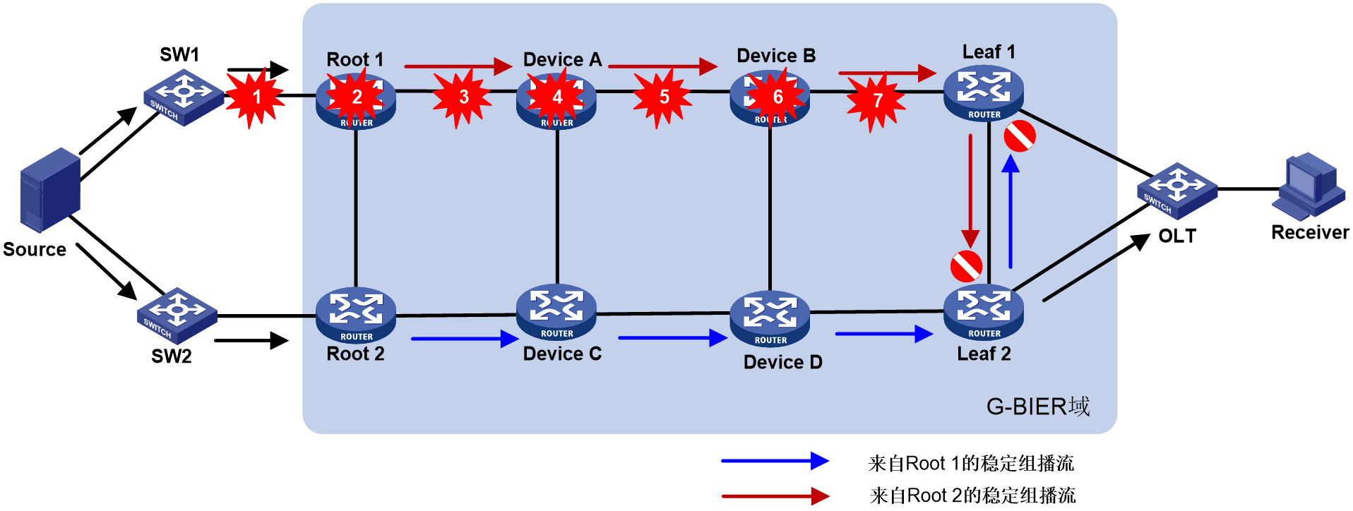
As shown in Figure 26, the reliability protection of multicast services carried by G-BIER includes three aspects: multicast source side, G-BIER domain, and multicast receiver (Rx) side.
· For multicast source reliability protection, a G-BIER domain dual-root 1+1 mechanism is used, where Root 1 and Root 2 serve as primary and backup roots, respectively. The multicast source connects to both roots through switches SW1 and SW2.
· For G-BIER domain reliability protection, a dual-stream mechanism is employed. Specifically, Root 1 and Root 2 of the G-BIER domain send identical multicast traffic to the leaf nodes (Leaf 1 and Leaf 2). Traffic monitoring is deployed on the leaf nodes for stable multicast streams. If traffic is not detected from the primary root's link, indicating a fault, the leaf node switches to receive multicast traffic from the backup root's link, significantly improving multicast service convergence speed and reliability. Intermittent streams do not have traffic monitoring (recovery relies on routing convergence).
· For receiver-side reliability protection, the approach involves OLTs using dual-device hot standby (S-Trunk, VRRP, etc.) for dual-homing access to the Leaf. The dual-homed Leafs form a protection group. The Leafs synchronize multicast table entries through dual-device hot standby. The hot standby and Leaf protection group work together to achieve switchover protection.
Figure 26 G-BIER dual-root 1+1 hot spare.

Under normal conditions, Leaf 1 and Leaf 2 receive two identical multicast streams from Root 1 and Root 2 through mutual backup. Leaf 1 selects Root 1 as the primary root based on routing preference and accepts traffic from Root 1 while discarding traffic from the backup Root 2. Leaf 2, following its routing preference, chooses Root 2 as the primary root, accepts traffic from Root 2, and discards traffic from the backup Root 1. Meanwhile, Leaf 1 and Leaf 2 use traffic selection rules to choose one device to forward the traffic to the OLT, which then sends it to the multicast receivers.
Fault detection and switchover
As shown in Figure 27, if any node along the path of multicast traffic from the source to the leaf nodes (Leaf) in the G-BIER domain fails, a reliability protection mechanism is required to ensure rapid traffic recovery.
Figure 27 Dual-Root 1+1 hot standby for multicast source side or failures within G-BIER domain (excluding leaf nodes)
1. Fault Detection
Leaf nodes Leaf 1 and Leaf 2 both perform traffic detection at regular periods. If a leaf node does not receive traffic from its respective main root node (Root 1 for Leaf 1, Root 2 for Leaf 2) within two periods, the current main root node is considered to be at fault.
2. Fault Switchover
a. When the primary root node fails, the leaf nodes switch to receiving traffic from the backup root.
b. After the primary root node recovers, the leaf nodes start receiving multicast traffic from the primary root again. To minimize unnecessary switching, traffic is processed according to different local configurations:
- Leaf 1 is set to non-revert mode, not switching back to receive traffic from Root 1, and continues to receive traffic from Root 2. It will only switch to receive traffic from Root 1 if it detects an interruption in the multicast stream from Root 2.
- If Leaf 1 is set to switch back mode, under the condition that the traffic from Root 1 is normal, after reaching the set waiting time for restoration, Leaf 1 will switch back to continue to receive (Rx) traffic from Root 1 and at the same time stop receiving (Rx) traffic from Root 2.
G-BIER OAM
G-BIER OAM (Operations, Administration, and Maintenance) is used to detect the connectivity of G-BIER forwarding paths and locate fault points in G-BIER paths. G-BIER OAM supports two diagnostic methods: Ping and Tracert.
· G-BIER Ping is used to check the connectivity of the G-BIER data plane (DP).
· G-BIER Tracert not only checks network connectivity for reachability but also analyzes where failures have occurred within the G-BIER network.
Both of these diagnostic methods first use IPv6 headers and UDP headers for inner encapsulation of OAM Request messages, then encapsulate the encapsulated OAM Request messages with an outer G-BIER header, and finally transmit them via BIER tunnels. The G-BIER OAM needs to open a UDP listening port on the response side, which is used to listen and receive OAM Request messages, the default UDP port number is 49100. After receiving the OAM Request message, the G-BIER OAM response end responds via UDP message.
G-BIER OAM message format.
The G-BIER OAM supports using G-BIER Echo Request/Reply messages for network diagnosis with both Ping and Tracert. The encapsulation format of the Echo Request/Reply messages is shown in Figure 28.
Figure 28 G-BIER OAM Echo Request message format.
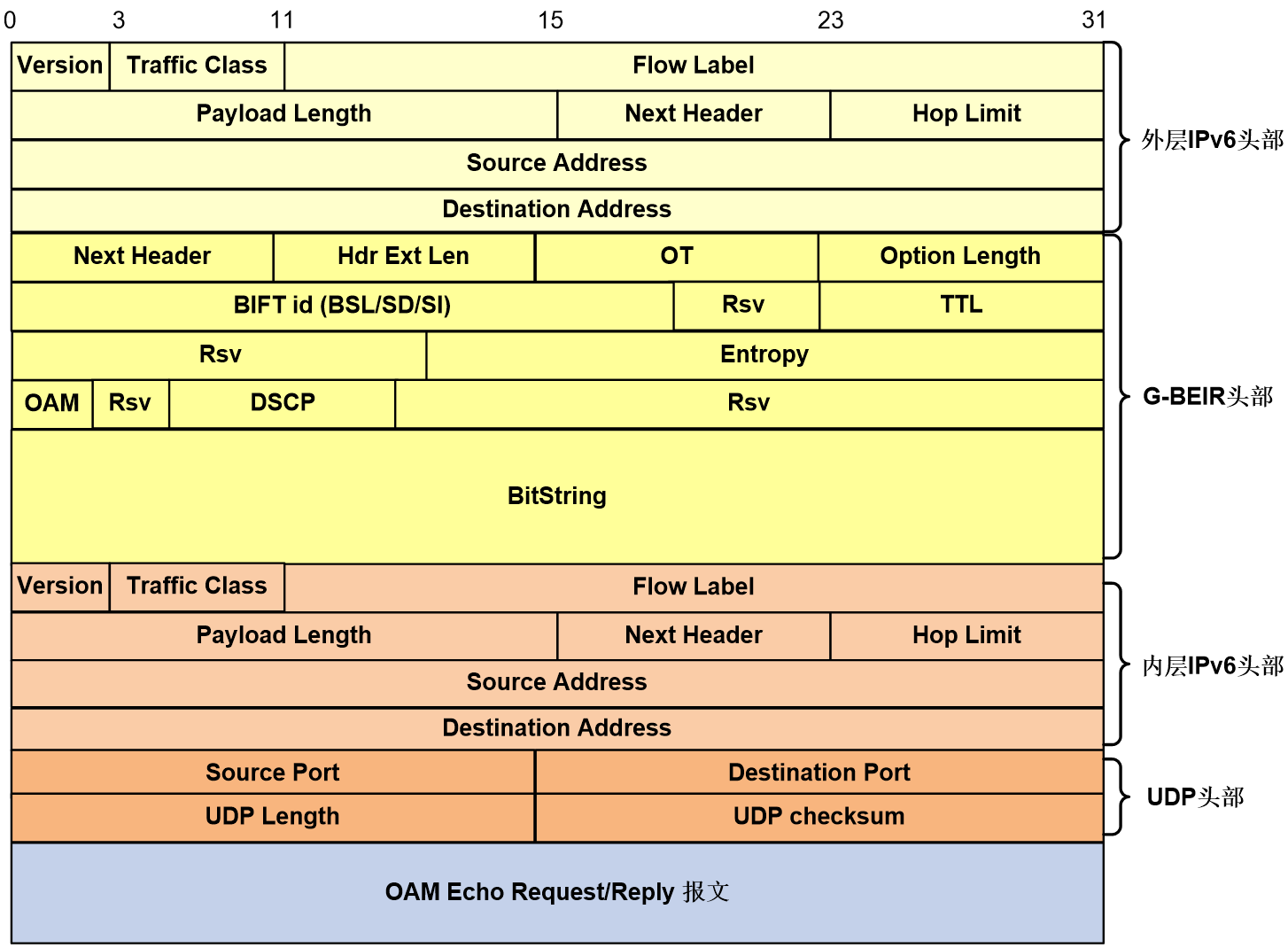
The meanings of each field in the G-BIER OAM Request/Reply message are as follows:
1. For a detailed introduction to the fields of the G-BIER header, please refer to G-BIER message format.
2. Inner Layer of IPv6 Header:
¡ Source Address: 32 bits, the IPv6 source address. For Request messages, the IPv6 source address is consistent with the IPv6 source address in the outer G-BIER header; for Reply messages, the IPv6 source address is the destination node's BFR prefix.
¡ Destination Address: 32 bits, the IPv6 destination address. For Request messages, it is a fixed value of 0:0:0:0:0:FFFF:7F00:1; for Reply messages, it corresponds to the outer IPv6 source address of the Request message.
3. UDP Header:
¡ Source Port: 16bits, it is the UDP source port number.
¡ Destination Port: 16 bits, the UDP destination port number.
¡ UDP Length: 16 bits, the length of the UDP datagram.
¡ UDP Checksum: 16 bits, the UDP checksum, which can verify whether data has been corrupted during transmission.
G-BIER Ping operating mechanism
The Ping of G-BIER is used to check the connectivity of the Underlay stratum. It does not rely on any multicast service configuration based on G-BIER. As long as the Underlay stratum of G-BIER is deployed, it can be carried out.
The basic process for handling Ping in G-BIER is as follows: An arbitrary node in the BIER domain initiates a G-BIER Echo Request message, and the target BFER node responds with a G-BIER Echo Reply message, completing the entire Ping process. If the initiating node does not receive a response from the target BFER node within a certain time, it prints a timeout information (Info).
The G-BIER Ping process is shown in Figure 29. The message information in the Ping process is exemplified by the message exchange between Device A → Device B → Device C → Device D.
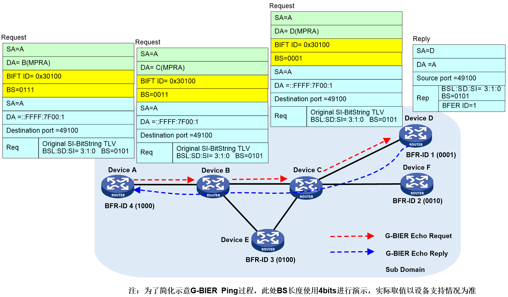
Device A (the ping initiator node) determines parameters specified by the command (such as the BFR ID list of the destination node), looks up the corresponding configuration of the local BIER subdomain, and obtains the BIER triple information (BSL, SD, SI). The BIFT ID can be uniquely determined through this triple information. Device A then searches the local G-BIER forwarding list through the BIFT ID and initiates the ping process.
1. Device A looks up the local G-BIER forwarding table using BIFT ID=0x30100, decides to forward the Echo Request message to neighbor Device B, and encapsulates it with Device B's MPRA as the destination IPv6 address and a BitString (BS) of "0011".
2. Upon reaching the intermediate nodes, Device B and Device C, the messages are multicast forwarded according to the G-BIER forwarding table until they reach the destination node.
3. The destination node Device D receives an Echo Request message and responds with an Echo Reply message to the source node Device A.
4. When Device A receives an Echo Reply message, if the key fields of the message do not match those in the Echo Request message sent by Device A, it will be ignored. If it matches, the response information is output.
5. If device A does not receive a response from the specified destination node within the designated waiting time, it will output timeout information.
Operation mechanism of G-BIER Tracert
The G-BIER Tracert operating mechanism includes the following three stages:
1. The source initiates the probe.
Start the first round of sniffer detection from BIER TTL=1, and continue subsequent detections at TTL = 2/3/4/....
2. Intermediate node processing
After receiving an Echo Request, if the BIER TTL in the G-BIER header has not decremented to 0, the node forwards it normally. If the BIER TTL reaches 0 and a forwarding table entry exists, it returns an Echo Reply message with Code 5 (Packet-Forward-Success, indicating successful packet forwarding). If no matching entry exists, it returns an Echo Reply with Code 8 (No matching entry in forwarding table).
3. The destination end should respond.
Upon receiving an Echo Request, the BFER node returns an Echo Reply message with Code 3 or 4.
¡ Code 3 (Replying BFR is the only BFER in header Bitstring): indicates that the destination reply BFR is the unique corresponding BFER for the BitString carried in the G-BIER OAM Echo Request message header.
¡ Code 4 (Replying BFR is one of the BFERs in header Bitstring): Indicates the responding BFR is one of the BFERs corresponding to the BitString carried in the G-BIER OAM Echo Request message header.
The BFR that has received a response will no longer participate in subsequent sniffing. When all nodes to be sniffed are finished, the sniffing can end. Completion of sniffing can either be when the source-end receives Echo Reply messages with Code 3 OR 4 from all nodes to be sniffed, or when the system default number of sniffs is reached. After the sniffing is completed, the source-end prints the path information to the sniffed BFER.
Round one of the G-BIER tracert process.
In the first round of the H3C-BIER tracert process (with BIER TTL=1), as shown in Figure 30.
Figure 30 First round of the G-BIER Tracert process.
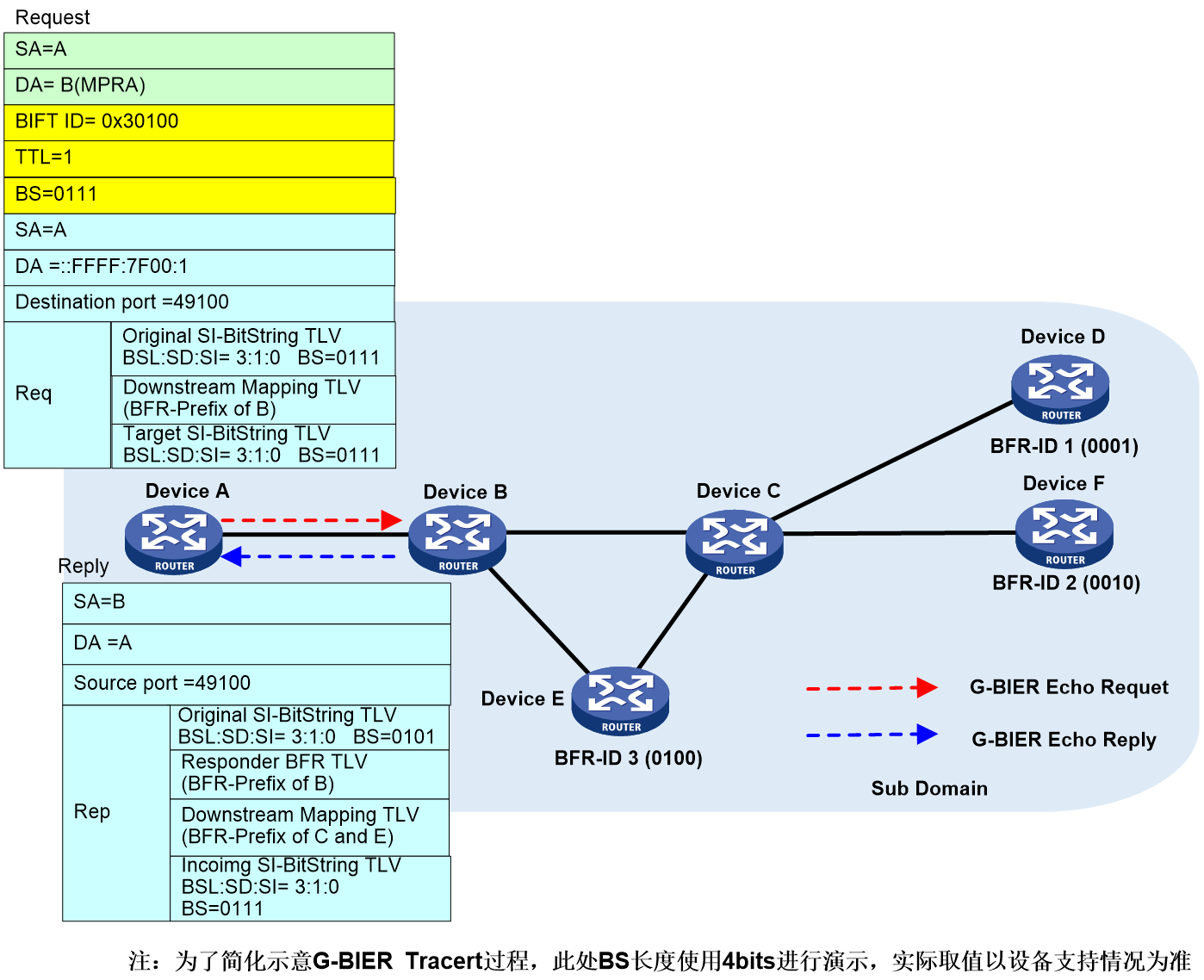
Device A (the initiating node for Tracert) follows the command-specified parameters (such as the BFR ID list of the destination node), finds the corresponding configuration of the local BIER subdomain, and obtains the BIER triplet information (BSL, SD, SI). This triplet information uniquely determines the BIFT ID. Then, Device A looks up the local G-BIER forwarding table through the BIFT ID and initiates the Tracert process.
1. Device A uses BIFT ID=0x30100 to search its local G-BIER forwarding table and decides to forward the G-BIER Echo Request message to neighbor Device B. The outer G-BIER encapsulation includes Device B's MPRA as the destination IPv6 address, a TTL of 1, and a Downstream Mapping TLV carrying Device B's BFR prefix.
2. After receiving the Echo Request message, Device B reduces the TTL to 0 and transmits an Echo Reply message to the initiating node. Since Device B is a Transit node, it passes the Echo Reply message, which carries the BFR prefix of downstream Devices C and E, via the Downstream Mapping TLV, while the Responder BFR TLV carries the BFR prefix of Device B.
3. After Device A receives the Echo Reply message, it matches the key fields of the message with the Echo Request message sent by Device A. If the match fails, this response message is ignored, otherwise, the response information is printed.
Round two of the G-BIER tracert process
The second round of the G-BIER Tracert
process (BIER TTL=2) is shown as depicted in Figure 31. The message information
in the Tracert process in the figure is exemplified by the second round of
message interactions from Device A to Device B to Device C to Device D.
Figure 31 The second round of the G-BIER Tracert process.

1. Device A looks up the local G-BIER forwarding table with BIFT ID=0x30100, and confirms to forward the G-BIER Echo Request to its neighbor, Device B. During the forwarding process, the destination IPv6 address encapsulated in the outer G-BIER is the MPRA of Device B, with a TTL of 2. The Downstream Mapping TLV carries the BFR prefix of Device C and Device E, copied from the previous Echo Reply.
2. Device B multicasts to Device C according to the G-BIER forwarding table.
3. Upon receiving the Echo Request message, Device C decrements the TTL to 0 and sends an Echo Reply back to the initiating node. As a transit node, Device C's Echo Reply includes a Downstream Mapping TLV with the downstream Device D's BFR prefix and a Responder BFR TLV with Device C's BFR prefix.
4. When Device A receives the Echo Reply, it matches key fields of the message with the Echo Request it sent. If the match fails, the response is ignored; otherwise, the reply information is printed.
Subsequent rounds are not detailed here, as the process is similar to the above.
G-BIER PHP
Introduction to G-BIER PHP
In the practical G-BIER network, there exist devices which support G-BIER on the control plane (C-Plane) but due to hardware (HW) limitations, don't support the transfer of it. At this time, it's necessary to activate the G-BIER penultimate hop popping (PHP) function on these types of devices. These devices, when flooding G-BIER information (Info) through the IS-IS protocol, will carry a G-BIER PHP field and announce (Annc) to other BFRs in the same BIER subdomain. They lack G-BIER forwarding ability. If other BFR devices during the G-BIER forwarding process discover this device as their next hop neighbor, they will pop out the DOH header (containing the G-BIER header) from the G-BIER package and transmit it to this device. After receiving (Rx) this package, according to the multicast routing table entry, this device will continue to transmit to downstream receivers.
G-BIER PHP device roles
G-BIER PHP Request nodes
In the G-BIER domain, a node that does not support G-BIER forwarding is called a G-BIER PHP Request node. Since this node lacks G-BIER forwarding capability, it cannot be used as a Transit BFR or BFIR, but only as a BFER. The G-BIER PHP function is configured on this node.
Node for G-BIER PHP Response
The BFR neighbor node of the G-BIER PHP Request node is referred to as the G-BIER PHP Response node. This node needs to pop out the DOH header when processing the messages forwarded to the G-BIER PHP Request node and then send them to the G-BIER PHP Request node.
G-BIER PHP Control Plane
As shown in Figure 32, Device D does not support G-BIER forwarding. A G-BIER PHP function must be deployed on Device D, the G-BIER PHP Request node. Device C is the BFR neighbor to Device D, acting as the G-BIER PHP Response node.
Device D issues a PHP request via IGP. On Device C, IGP calculates the G-BIER shortest path tree using the received G-BIER information, with BFIR as the root and Transit BFRs and BFERs as leaves. The BFR creates a BIRT based on this tree, which then generates a BIFT to guide G-BIER forwarding. When building the G-BIER shortest path tree, for the BFER node Device D that doesn't support G-BIER forwarding, Device C creates a corresponding G-BIER BIFT entry upon receiving Device D's IGP advertisement. This BIFT entry notes that the DOH header should be popped for the G-BIER neighbor, Device D. The resulting BIFT entries on each node are as shown in Figure 32, with no BIFT entries generated or maintained on Device D.
Figure 32 The control plane (C Plane) for G-BIER PHP.

G-BIER PHP Forwarding Plane
The specific forwarding process of devices supporting G-BIER forwarding capability can be found in "BIER forwarding process", and will not be repeated here. This section focuses on the forwarding process of G-BIER Request and Response nodes.
As illustrated in Figure 33, upon receiving the G-BIER message transmitted by Device B, Device C will look up its BIFT entry. It finds that when forwarding the G-BIER message to its neighbor, Device D, it's necessary to pop out the DOH header before sending it to Device D. After receiving a message whose target is the local MPRA and doesn't carry a DOH header, Device D will identify the MVPN-instance based on the MSID found in the IPv6 source address, remove the outer IPv6 encapsulation. It then forwards the encapsulated multicast data according to the corresponding entry in the VPN's multicast forwarding table.
Figure 33 G-BIER PHP Forwarding Plane
BIERv6 technical implementation
BIERv6 (Bit Index Explicit Replication IPv6 Encapsulation) is a fresh multicast scheme based on Native IPv6. It combines the benefits of IPv6 and BIER, which allows seamless integration into SRv6 network, simplifying protocol complexity. When configuring the encapsulation type of BIER-carrying messages to BIERv6, all BFRs in the BIER subdomain are required to support SRv6.
BIERv6 message format
The encapsulation of BIERv6 messages is implemented by adding a new IPv6 base header and BIERv6 header in front of the multicast datagram. As shown in Figure 34, the Next Header value in the IPv6 base header is 60, indicating that the next message header is the DOH (Destination Options Header).
For BIERv6 packets, the following conventions are applied in the IPv6 base header:
· The source address needs to be configured as the source address of the BIERv6 tunnel. This source address remains unchanged when the multicast packet is forwarded in the public network. For a detailed explanation of the BIERv6 tunnel source address, please refer to "Multicast VPN" in the "IP Multicast Configuration Guide".
· The Destination Address needs to be configured as the End.BIER SID, which is specifically used for BIER forwarding. This address should be reachable through intra-domain routing within the subdomain.
The BIERv6 header primarily consists of the following parts:
· Next Header: 8bits, used to identify the type of the next message header.
· Hdr Ext Len: 8bits, it represents the length of the IPv6 extension header.
· Option Type: 8bits, the option type is BIERv6.
· Option Length: 8 bits, indicating the length of the BIERv6 message header.
· BIFT-ID: a 20-bit unique index that identifies a BIFT (Bit Index Forwarding Table) for forwarding purposes.
· TC, short for Traffic Class and consisting of 3 bits, is used for QoS and refers to the rank of traffic.
· S: 1bits, a reserved field.
· TTL: 8 bits, indicating the hop count of a message after BIERv6 forwarding processing. After passing through a BIERv6 forwarding node, the TTL value decreases by 1. When the TTL is 0, the message is discarded.
· Nibble: 4 bits, a reserved field, currently only supports 0.
· The version, indicated as 4bits, is the version number of BIERv6 packets. Currently, it only supports 0.
· BSL: 4bits, using 1-7 to represent different bit string lengths. The corresponding relationship between the value and bit string length is as follows:
¡ 1: Indicates a bit string length of 64 bits.
¡ 2: Indicates a bit string length of 128 bits.
¡ 3: Indicates a bit string length of 256 bits.
¡ 4: Indicates a bit string length of 512 bits.
¡ 5: Indicates a bit string length of 1024 bits.
¡ 6: Indicates a bit string length of 2048 bits.
¡ 7: Indicates a bit string length of 4096 bits.
· Entropy: 20 bits, used to select paths when equivalent routes exist. Messages with the same Bit String and Entropy value will choose the same path.
· OAM: 2bits, defaults to 0, can be used for the OAM function.
· Rsv: 2 bits, a reserved field, defaulting to 0.
· DSCP: 6 bits, the message's own priority level, determining the precedence of message transmission.
· Proto: 6bits, it is an ID for the next layer protocol, used for identifying the Payload type after the BIERv6 message header.
· BFIR ID: 16 bits, the BFR ID value of the BFIR.
· Bit String: A sequence of bits.
Figure 34 BIERv6 message encapsulation diagram
BIERv6 forwarding process
The forwarding process of BIERv6 is similar to BIER. Please refer to "BIER forwarding process"
BIERv6 control plane
IS-IS BIERv6 expansion
RFC8401 has outlined the information release mechanism for BIER's sub-domain. Please refer to IS-IS BIER expansion. IS-IS BIERv6 has expanded BIER Info Sub-TLV, introducing the following two new sub-sub-TLV types:
1. BIERv6 encapsulation information sub-sub-TLV
The BIERv6 passes on the Max-SI and BSL of this node by adding a new BIERv6 encapsulation information sub-sub-TLV in the BIER Info Sub-TLV. The specific format of this sub-sub-TLV is shown as Figure 35.
Figure 35 BIERv6 encapsulation information sub-sub-TLV.
The meanings of each field in the BIERv6 encapsulation information sub-sub-TLV are as follows:
¡ Type: 8 bits, the type of sub-sub-TLV, with a value of 6, represents carrying encapsulation information for BIERv6.
¡ The TLV length is 8 bits.
¡ Max-SI: 8 bits, the maximum identify (ID) value in BIERv6 subdomain.
¡ BSL: 4 bits, bit string length.
¡ Reserved: 20 bits, a reserved field for byte alignment.
2. BIERv6 End.BIER sub-sub-TLV
BIERv6 requires the configuration of a specific End.BIER SID on BFR for BIER forwarding, and it releases this node's End.BIER SID through IS-IS, to notify other neighbors to use this IPv6 address as the IPv6 destination address when transmitting BIERv6 packets to this node.
As part of the BIERv6 encapsulation, the End.BIER address needs to be released by adding a new BIERv6 End.BIER sub-sub-TLV in the BIER Info sub-TLV. The format of this sub-sub-TLV is shown in Figure 36.
Figure 36 End of BIERv6. Sub-Sub-TLV of BIER.
The meanings of each field in the BIERv6 End.BIER sub-sub-TLV are as follows:
¡ Type: 8 bits, the type of sub-sub-TLV, with a value of 3, indicating it carries the End.BIER SID.
¡ Length: 8 bits, representing the length of the TLV (Type-Length-Value) structure.
¡ End.BIER SID: 128 bits, End.BIER address.
¡ Extension: No specific format or its meaning supplement is currently defined, and no processing is performed.
NG MVPN over BIERv6
NG MVPN over BIERv6 control plane
In the NG MVPN over BIERv6 scenario, BIERv6 is used to establish a carrying tunnel. Multicast private network traffic is encapsulated by BIERv6 and sent across the public network to other nodes in the BIER sub-domain.
The control plane of NG MVPN over BIERv6 includes the following unique technical implementations:
· Receiver PE information collection
In this scenario, the multicast source-side PE first learns which receiver-side PEs need to receive the multicast traffic, and then encapsulates the Bit String based on the received private network multicast traffic. The collection mechanism for PE members in MVPN is similar to the process in MVPN with RSVP-TE and mLDP modes.
· Addition of new BIER tunnel attributes
To support NG MVPN over BIERv6, RFC8556 defines the necessary information when using BIER tunnel in BGP MVPN service, which is a BIER type of PTA (PMSI Tunnel attribute). The aforementioned BIER type of PTA is used when using BIERv6 tunnel in BGP MVPN service. The original MPLS Label field in the PTA, used to identify the upstream allocation label of the MVPN-instance, is no longer used in the MVPN based on the BIERv6 tunnel. Instead, a new BGP property containing the IPv6 source address (src-dt4 or src-dt6) for identifying the MVPN-instance is used, known as Prefix-SID. Consequently, the value of the MPLS Label field in the PTA is set to 0.
MVPN BGP protocol extensions
Prefix-SID Property
In MVPN over BIERv6, the BGP attribute Prefix-SID is used to carry the IPv6 source address encapsulated by the BIERv6 tunnel. The multicast source-side PE advertises the tunnel source address to the receiver-side PE by carrying the Prefix-SID in Type 1 routes, Intra-AS I-PMSI A-D routes, and Type 3 routes, S-PMSI A-D routes. Upon receiving Type 1 and Type 3 routes, the receiver-side PE matches the Route Target attribute carried by the route with the local VPN instance or public network instance and records the relationship between the Prefix-SID and the VPN or public network instance. When the receiver-side PE receives a multicast packet encapsulated by BIERv6, it identifies the corresponding VPN or public network instance based on the BIERv6 tunnel source address in the packet, establishes multicast forwarding table entries in the corresponding MVPN instance, and forwards the multicast packet.
The BGP Prefix-SID attribute and its contents follow the format requirements defined by the RFC standard, as shown in Figure 37.
Figure 37 BGP Prefix-SID Format
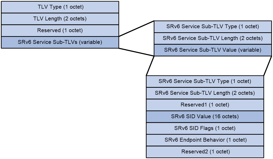
The meanings of each field in the BGP Prefix-SID are as follows:
· TLV Type: This is the type of TLV. A value of 5 means that SRv6 carries a three-stratum service; a value of 6 means that SRv6 carries a two-stratum service.
· TLV Length: The length of the TLV.
· Reserved: Reserved field.
· SRv6 Service Sub-TLVs: The service information related to Prefix-SID, which is of variable length.
The SRv6 Service Sub-TLV package contains the following fields:
· Service Sub-TLV Type in SRv6: The type of Prefix-SID information is fixed at 1, indicating SRv6 SID Information Sub-TLV.
· SRv6 Service Sub-TLV Length: The length of the SRv6 Service Sub-TLV.
· SRv6 Service Sub-TLV Value: The value of the SRv6 Service Sub-TLV, which is variable in length.
When the type is SRv6 SID Information Sub-TLV, the SRv6 Service Sub-TLV includes the following fields:
· SRv6 Service Sub-TLV Type: The type of SRv6 Service Sub-TLV, with a fixed value of 1.
· SRv6 Service Sub-TLV Length: The length of the SRv6 SID Information Sub-TLV.
· Reserved1: A reserved field.
· SRv6 SID Value: The value of the Prefix-SID, representing the Src.DT4 SID and Src.DT6 SID for the BIERv6 tunnel source address, is carried by this field.
· SRv6 SID Flags: The flags for the Prefix-SID, with a fixed value of 0.}
· SRv6 Endpoint Behavior: The type of Prefix-SID. A value of 0x45 indicates a Src.DT4 SID, and 0x44 indicates a Src.DT6 SID.
· Reserved2: A reserved field.
MVPN extended community attributes
1. Introduction to MVPN Extended Community Attribute
MVPN's extended community attributes are primarily used for the advertisement and reception of C-multicast routes, including the following two types:
· The Source AS Extended Community property is used to identify the AS number where the multicast source is located, applicable in cross-domain scenarios.
· The VRF Route Import Extended Community attribute is used to identify the IP address of the multicast source-side PE and the VPN-instance where the multicast source is located.
The format of Source AS Extended Community and VRF Route Import Extended Community within the extended community attribute is depicted respectively in Figure 38 and Figure 39.
Figure 38 Format of the Source AS Extended Community

The Source AS Extended Community package includes the following fields:
· Type: The type of the extended community attribute, which can either be 0x00 (representing the extended community attribute of a 2-byte AS number type) OR 0x02 (representing the extended community attribute of a 4-byte AS number type).
· Sub-Type: The subtype of the extended community attribute, with a value of 0x09, indicating it is a Source AS Extended Community.
· Global Administrator: The AS number, where the multicast source is located, can be in either a 2-byte format or a 4-byte format.
· Local Administrator: Has a value of 0, currently without special meaning.
Figure 39 Format of the VRF Route Import Extended Community
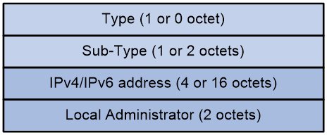
The VRF Route Import Extended Community includes the following fields:
· Type: The type of the extended community attribute, with a value of 0x01 (for IPv4 address type extended community attribute) or no value (for IPv6 address type extended community attribute).
· Sub-Type: The subtype of the extended community attribute, with a value of 0x0b (when it's an IPv4 address type extended community attribute) or 0x000b (when it's an IPv6 address type extended community attribute), indicating it is a VRF Route Import Extended Community.
· IPv4/IPv6 address: The IP address of the multicast source-side PE.
· Local Administrator: The VPN instance where the multicast source is located.
2. The working mechanism of MVPN extended community attributes
As shown in Figure 40, PE 1 and PE 2 are multicast source PEs, while PE 3 is a receiving-side PE. Both PE 1 and PE 2 are connected to VPN 1 and the public network instance sites. On PE 1, the VRF Route Import Extended Community value for VPN 1 is 1.1.1.1:1; for the public network instance on PE 1, the value is 1.1.1.1:0 (the Local Administrator value in the VRF Route Import Extended Community for the public network instance must be 0); the Source AS Extended Community value on PE 1 is 10:0. On PE 2, the VRF Route Import Extended Community value for VPN 1 is 2.2.2.2:1; for the public network instance on PE 2, the value is 2.2.2.2:0 (the Local Administrator value in the VRF Route Import Extended Community for the public network instance must be 0); the Source AS Extended Community value on PE 2 is 10:0.
Figure 40 MVPN extended community attributes working mechanism

After establishing BGP MVPN address family sessions with PE 3 respectively, both PE 1 and PE 2 will release unicast route information to the multicast source to PE 3. The multicast source unicast route information of VPN-instance is carried via BGP VPNv4 or VPNv6 routes. The public network instance's multicast source unicast route information is carried via BGP IPv4/IPv6 unicast routes OR BGP IPv4/IPv6 multicast routes. All BGP routes carrying the announced unicast route information to the multicast source will include Source AS Extended Community and VRF Route Import Extended Community.
Upon receiving the BGP routes of unicast routing information to multicast sources announced by PE 3, PE 3 will prefer the BGP routes, then store the Source AS Extended Community and VRF Route Import Extended Community carried by the routes for later construction of the C-multicast route. It is assumed in this instance that PE 3 has preferred the BGP route of the unicast routing information to the multicast source of VPN 1 announced by PE 1, and the BGP route of the unicast routing information to a multicast source of a public network instance announced by PE 2.
The construction process of C-multicast routing for VPN-instance VPN 1 and public network instance is as follows:
· When PE 3 receives a multicast join message from CE 3, it constructs a C-multicast route, and then transmits it to PE 1 and PE 2. The Source AS field of this route is the AS number in the received Source AS Extended Community. The Route Target properties carried by the route is the VRF Route Import Extended Community of the preferred BGP route, which is 1.1.1.1:1.
¡ Upon receiving the C-multicast routing, PE 1 compares the IP address carried in the RT properties of the C-multicast routing and discovers it is 1.1.1.1, which is the local source interface address. So, PE 1 accepts the C-multicast routing. Then, PE 1 determines the C-multicast routing belongs to VPN-instance VPN 1 based on the Local Administrator in the RT properties and adds the C-multicast routing to the multicast routing table of VPN 1.
¡ Upon receiving the C-multicast route, PE 2 compares the IP address carried in the RT attribute of the C-multicast route, identifies it as 1.1.1.1, which is not the local source interface address, and discards the C-multicast route.
When the multicast source in VPN 1 sends multicast packets subsequently, as only PE 1 has formed the multicast entry, the multicast packets will be encapsulated by BIERv6 at PE 1 and transmitted through the BIERv6 public network tunnel to PE 3. After decapsulation at PE 3, they are forwarded to CE 3.
· When PE 3 receives a multicast join message from CE 4, it constructs a C-multicast route and then sends it to PE 1 and PE 2. The Source AS field of this route is the AS number from the received Source AS Extended Community, and the Route Target properties it carries are the VRF Route Import Extended Community of the preferred BGP route, which is 2.2.2.2:0.
¡ Upon receiving the C-multicast route, PE 2 compares the IP address in the RT attribute of the route, recognizes it as 2.2.2.2, which is the local source interface address, and accepts the C-multicast route. Then, PE 2 uses the Local Administrator in the RT attribute to determine that the C-multicast route belongs to the public network instance and adds the route to the multicast routing table of the public network instance.
¡ Upon receiving the C-multicast route, PE 1 compares the IP address carried in the RT properties of the C-multicast route and finds out that it is 2.2.2.2, not the local source interface address, thus discards the C-multicast route.
When the multicast source in the public network instance subsequently transmits multicast packets, since only PE 2 forms the multicast entry, the multicast packets will be encapsulated in BIERv6 at PE 2, and then transmitted to PE 3 through the BIERv6 public network tunnel. After decapsulation on PE 3, the packets are forwarded to CE 4.
H3C NG MVPN over BIERv6 run mechanism
The operation mechanism of NG MVPN over BIERv6 is similar to that of G-BIER. For details, please refer to ''Operation mechanism of NG MVPN over G-BIER''
NG MVPN over BIERv6 forwarding process
The process of NG MVPN over BIERv6 forwarding is illustrated in Figure 41.
Figure 41 The forwarding process of NG MVPN over BIERv6.
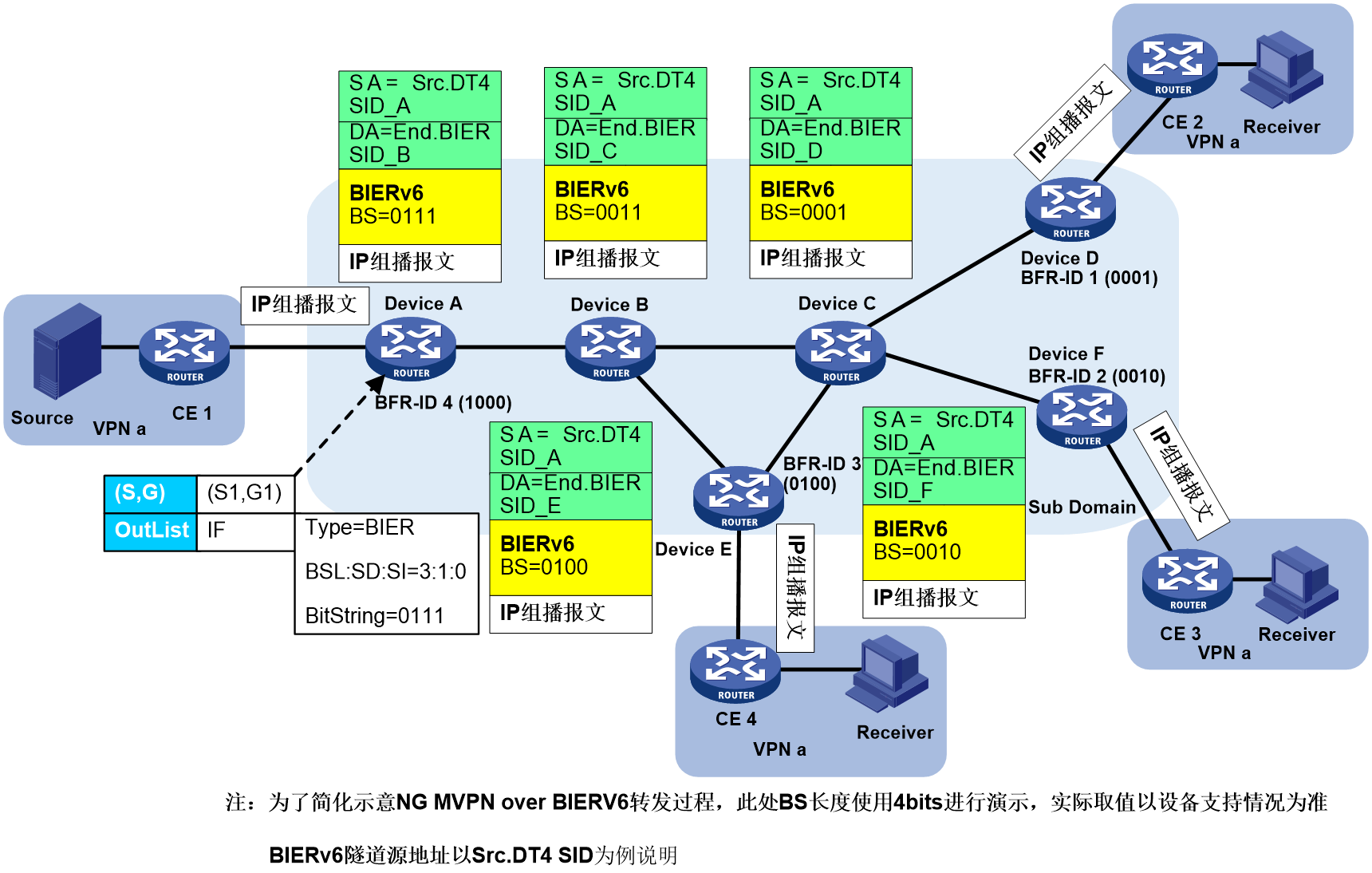
1. Device A (Ingress PE node, BIERv6 domain BFIR node) receives a multicast packet from MVPN instance CE 1. It then proceeds with the following processing steps:
a. Search for the multicast forwarding table corresponding to the MVPN instance, ascertain the multicast packet is forwarded on a BIER type PMSI tunnel, and retrieve the BIFT ID as 0x30100 and Bit String as 0111 for BIER PMSI.
b. Find the local BIERv6 forwarding table based on BIFT ID and Bit String, then determine to forward to neighbor Device B.
c. Copy the multicast packet and encapsulate the IPv6 destination address as End.BIER SID of Device B. The BIER encapsulation's BIFT ID is 0x30100 and the Bit String is 0011, which is obtained by a bitwise AND operation on '0111' and the F-BM value '0011' corresponding to Device B in the BIFT.
2. Device B receives a packet and matches the destination address with the locally configured End.BIER SID. If it successfully matches, BIERv6 forwarding is executed; otherwise, regular IP forwarding is performed. Upon a successful match, the local BIERv6 forwarding table is searched based on BIFT ID=0x30100 and BitString=0011 to determine forwarding to neighbors Device C and Device E. Taking forwarding to Device E as an example, the multicast packet is duplicated, the IPv6 destination address is encapsulated as Device E's End.BIER SID, and the BIER encapsulation includes a BIFT ID of 0x30100 and a Bit String of 0100 (obtained by performing a bitwise AND operation on "0011" and F-BM value "0100" corresponding to Device E in BIFT).
3. Device E receives a packet and compares the destination address with the locally configured End.BIER SID. If a match is successful, it executes End.BIER SID forwarding; otherwise, it performs standard IP forwarding. At the same time, if the encapsulated Bit String in BIER matches the node's BFR ID corresponding Bit String, this indicates the node is a BFER and will perform decapsulation on the BIERv6 packet for subsequent multicast forwarding. By decapsulating the IPv6 header and BIERv6 header from the BIERv6 packet, an IP multicast packet is obtained. The IP multicast packet will be forwarded according to the multicast forwarding table associated with the MVPN-instance.
Reliability protection of BIERv6
The implementation of reliability protection for BIERv6 is similar to that of G-BIER class, please refer to "Reliability protection of G-BIER".
BIERv6 OAM
BIERv6 OAM (Operations, Administration, and Maintenance) is used to detect the connectivity of BIERv6 forwarding paths and to identify fault points in BIERv6 paths. BIERv6 OAM supports two diagnostic methods: Ping and Tracert.
· BIERv6 Ping is used to check the connectivity of the BIERv6 data plane (DP).
· BIERv6 Tracert not only checks if the network connection is reachable, but also analyzes where a fault has occurred within the BIERv6 network.
Both diagnostic methods first use the IPv6 and UDP headers to encapsulate the inner layer of the OAM Request message, then encapsulate the outer layer using the BIERv6 header. Finally, the message is transmitted through a BIERv6 tunnel. BIERv6 OAM requires a UDP listening port to be opened on the response end to listen and receive the OAM Request message. The default UDP port number is 49100. Once the OAM Request message is received by the BIERv6 OAM response end, it replies through a UDP message.
BIERv6 OAM message format
BIERv6 OAM supports Ping and Tracert, both of which use BIERv6 Echo Request/Reply messages for network diagnostics. The encapsulation format of Echo Request/Reply messages is shown in Figure 42.
Figure 42 BIERv6 OAM Echo Request message format
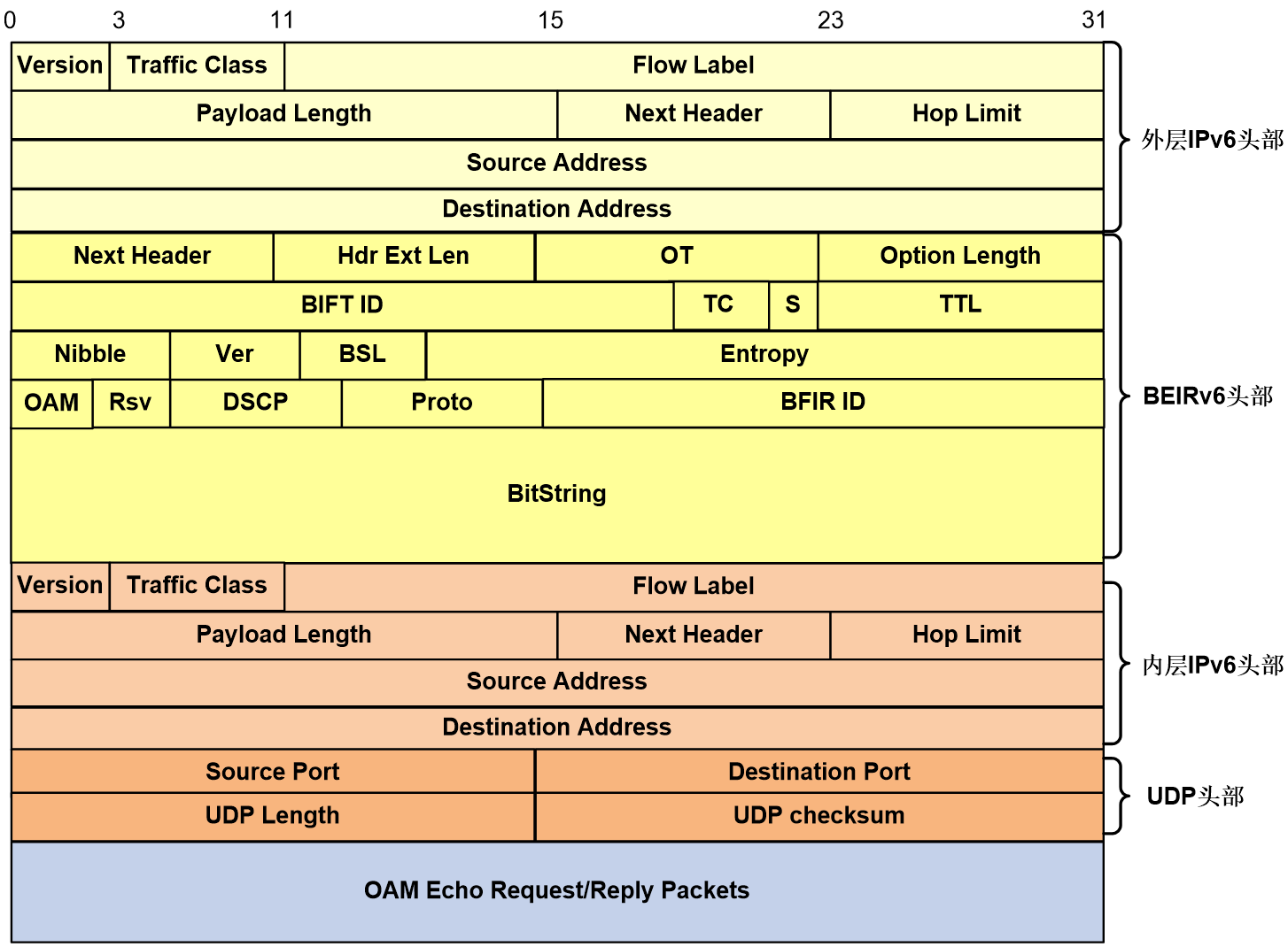
The meanings of each field in the BIERv6 OAM Request/Reply message are as follows:
1. For a detailed introduction to the BIERv6 header fields, please refer to "BIERv6 message format" under section 4.1.
2. Inner Layer of IPv6 Header:
¡ Source Address: 32bits, IPv6 source address. For Request messages, the IPv6 source address remains consistent with the outer stratum IPv6 source address; for Reply messages, the IPv6 source address is the destination node's BFR prefix.
¡ Destination Address: 32bits, IPv6 destination address. For Request messages, the fixed value is 0:0:0:0:0:FFFF:7F00:1; for Reply messages, it corresponds to the outer IPv6 source address of the Request messages.
3. UDP Header:
¡ Source Port: 16bits, UDP source port number.
¡ Destination Port: 16 bits, UDP destination port number.
¡ The UDP Length, expressed in 16 bits, represents the length of the UDP datagram.
¡ UDP Checksum: a 16-bit value for verifying if data has been damaged during transmission.
BIERv6 ping mechanism
The Ping of BIERv6 is used to detect the connectivity of the Underlay stratum. It doesn't depend on any multicast service configurations based on BIERv6. As long as the Underlay stratum of BIERv6 is fully deployed, it can be performed.
The basic process of ping processing in BIERv6 is as follows: an arbitrary node in the BIER domain initiates a BIERv6 Echo Request message, and the target BFER node responds with a BIERv6 Echo Reply message, completing the entire ping process. If the initiating node does not receive a response from the target BFER node within a certain period of time, it will print a timeout information.
The process of BIERv6 Ping is illustrated in Figure 43. The message information of the Ping process in the figure demonstrates the message interaction between Device A, Device B, Device C, and Device D.
Figure 43 The Process of BIERv6 Ping
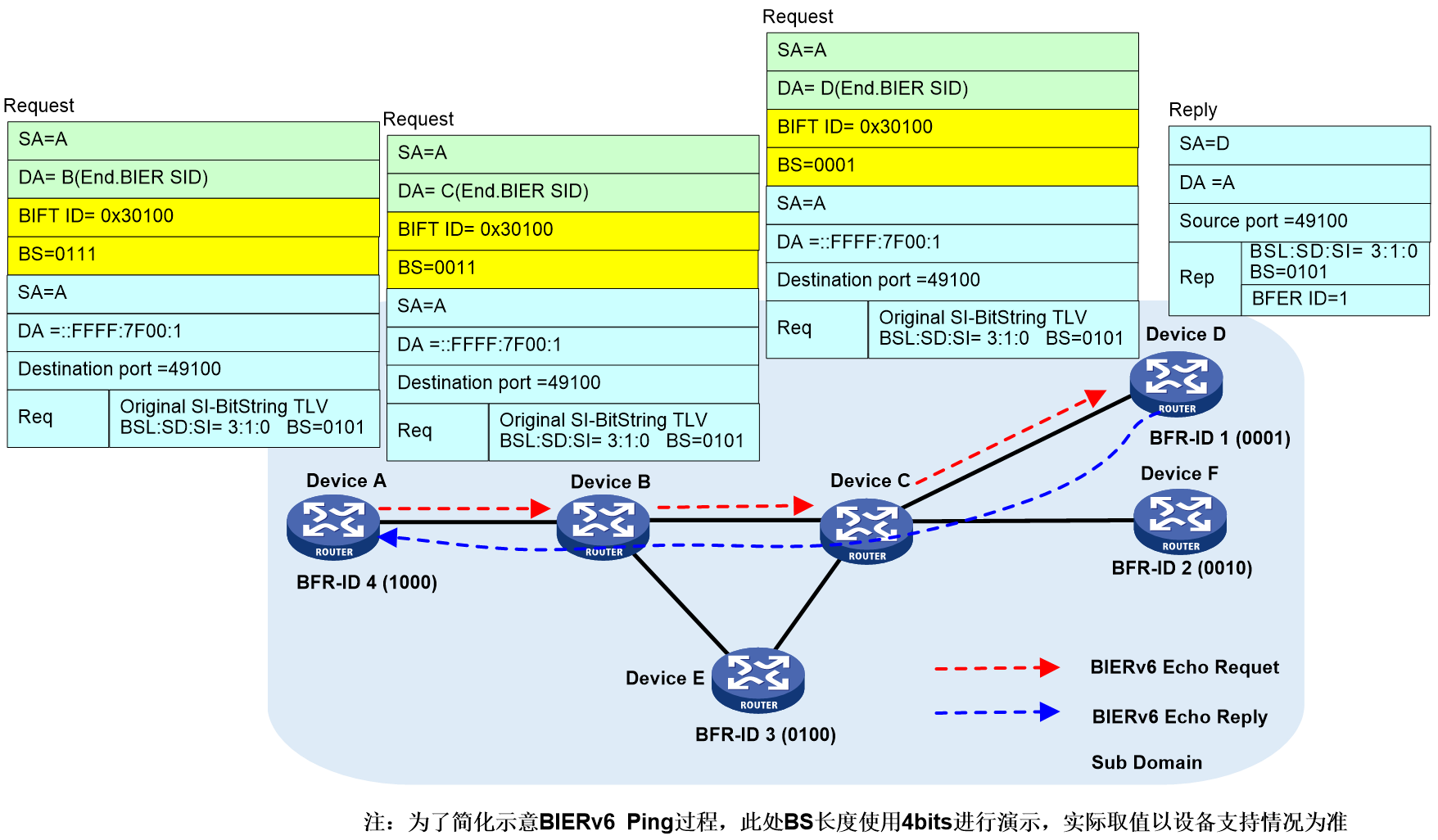
Device A (the initiating node of Ping) determines the BIFT ID uniquely through the triplet information (BSL, SD, SI) obtained from the corresponding configuration of local BIER subdomain, according to the parameters specified by the command (such as the BFR ID list of the destination node). The Ping process is then initiated by referring to the local BIERv6 forwarding table through the BIFT ID.
1. Device A searches its local BIERv6 forwarding table using BIFT ID=0x30100 and determines to forward the Echo Request message to neighbor Device B. During transmission, the outer BIERv6 encapsulation's destination IPv6 address is Device B's End.BIER SID, with BS set to "0011".
2. After the packets arrive at the intermediate nodes, Device B and Device C, these nodes forward the multicast based on the BIERv6 forwarding table until they reach the destination node.
3. The destination node Device D receives an Echo Request message and replies with an Echo Reply message to the source node Device A.
4. When Device A receives an Echo Reply message, if the key fields of the message do not match with those in the Echo Request message sent by Device A, then it will be ignored. If it matches, then response information will be output.
5. If device A does not receive a response from the specified destination node within the designated wait time, it will output timeout information.
BIERv6 Tracert mechanism
The operation mechanism of BIERv6 Tracert includes the following three stages:
1. The source end initiates a sniffer.
Start the first round of sniffer detection from BIER TTL=1, and continue with subsequent detections at TTL = 2/3/4/....
2. The intermediate node is processing.
When the intermediate node receives an Echo Request, if the BIER TTL in the BIERv6 header has not been reduced to 0, it is normally forwarded. If the BIER TTL is reduced to 0, and there is an entry in the forwarding table, a Packet-Forward-Success Echo Reply message with Code 5 is returned. If there is no matching entry in the BIERv6 forwarding table, an Echo Reply message with Code 8 (No matching entry in forwarding table) is returned.
3. The destination end should respond.
Upon receiving an Echo Request, the BFER node returns an Echo Reply message with a Code of 3 OR 4.
¡ Code 3 (Replying BFR is the only BFER in header Bitstring): Indicates that the destination replying BFR is the only BFER corresponding to the BitString carried in the BIERv6 OAM Echo Request message header.
¡ Code 4 (Replying BFR is one of the BFER in header Bitstring) means that the destination BFR responding is one of the BFERs in the BitString carried by the BIERv6 OAM Echo Request message header.
BFRs that have received a response no longer participate in subsequent sniffing. Sniffing can be completed when all nodes to be sniffed are finished. Completion of sniffing can be either the source end receiving Echo Reply messages with Code 3 OR 4 from all nodes to be sniffed, OR reaching the system's default sniffer count. After sniffing is completed, the source end prints the path information to the sniffed BFER.
First round of BIERv6 tracert process
The first round of the BIERv6 Tracert process (with BIER TTL=1) is shown in Figure 44.
Figure 44 In the first round of the BIERv6 tracert process.

Device A, as the initiating node of Tracert, looks up the local BIER subdomain configuration as per the parameters specified by the command (like the destination node's BFR ID list), and obtains the BIER triplet info (BSL, SD, SI). This triplet info uniquely identifies the BIFT ID, and Device A uses this BIFT ID to look up the local BIERv6 forwarding table and initiates the Tracert process.
1. Device A searches the local BIERv6 forwarding table according to BIFT ID=0x30100, determines to forward the BIERv6 Echo Request message to the neighbor Device B. When forwarding, the destination IPv6 address encapsulated in the outer BIERv6 layer is Device B's End.BIER SID, with TTL as 1, and the Downstream Mapping TLV carries Device B's BFR prefix.
2. Upon receiving the Echo Request message, Device B reduces the TTL to 0 and transmits an Echo Reply message to the initiating node. As Device B serves as a Transit node, the transmitted Echo Reply message carries the BFR prefixes of downstream Device C and Device E through the Downstream Mapping TLV. The Responder BFR TLV carries the BFR prefix of Device B.
3. After receiving the Echo Reply message, Device A matches the key fields of the message with the Echo Request message that Device A sent. If the matching fails, this response message is ignored, otherwise, the response information is printed.
Second round of the BIERv6 Tracert process
The second round process of BIERv6 Tracert (BIER TTL=2) is shown in Figure 45. The message information of the Tracert process in the figure illustrates the second round of message interaction from Device A to Device B to Device C to Device D as an example.
Figure 45 The second round of the BIERv6 tracert process.
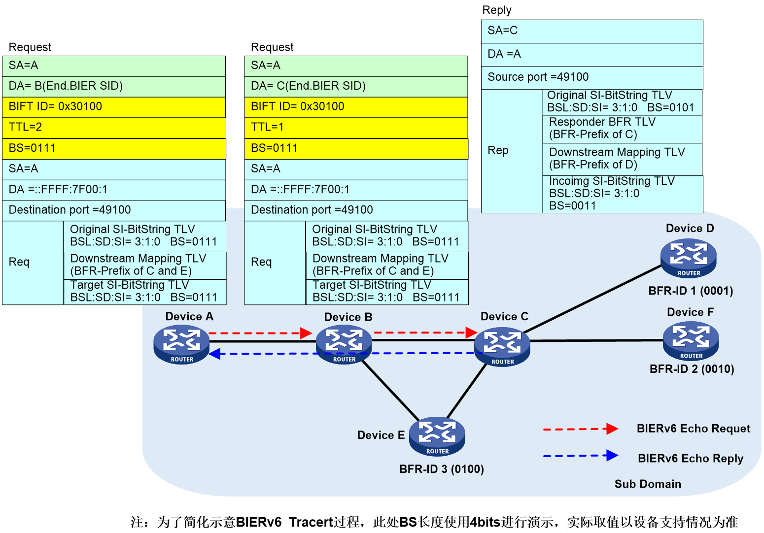
1. Device A, by using the BIFT ID=0x30100, locates its local BIERv6 forwarding table and decides to transmit the BIERv6 Echo Request to its neighbor, Device B. The outer encapsulation of BIERv6 in transit has the destination IPv6 address as the End.BIER SID of Device B, with a TTL of 2. The Downstream Mapping TLV carries the BFR prefix of Device C and Device E, which is copied from the Echo Reply of the previous round.
2. Device B multicasts according to the BIERv6 forwarding table and forwards it to Device C.
3. After receiving the Echo Request message, Device C reduces the TTL to 0, and transmits the Echo Reply message to the initiating node. As a Transit node, Device C sends an Echo Reply message with a Downstream Mapping TLV that carries the BFR prefix of the downstream Device D. The Responder BFR TLV carries the BFR prefix of Device C.
4. After Device A receives the Echo Reply message, it matches the key field of the message with the Echo Request message sent by Device A. If the match fails, it ignores this response message, otherwise, it prints the response information.
Following rounds will not be elaborated on, processing is similar to the above-mentioned class.
Typical network applications
Public network multicast scenario
The IPv6 provincial backbone network and the IPv6 metropolitan area network (MAN) are in different autonomous domains. The multicast source accesses the provincial backbone router PB via the provincial backbone service router PSR, providing IPTV services from the carrier network to the home/enterprise network for terminal users in the MAN. To ensure high availability (HA) of insured traffic, a dual hot spare method is employed. PSR 1 and PSR 2 act as primary and backup network paths for BIER respectively. The multicast source connects with the primary and backup paths respectively via Ethernet switches SW 1 and SW 2.
In IPTV services where BIER technology is used, there is no need to establish a multicast distribution tree from multicast source nodes to multicast receiver nodes. The intermediate nodes do not need to run a Multicast Routing Protocol, nor maintain multicast forwarding states. This meets the requirements for quick addition of multicast users and rapid deployment of multicast services.
Figure 46 Deploying BIER multicast services on the public network is a typical networking application.
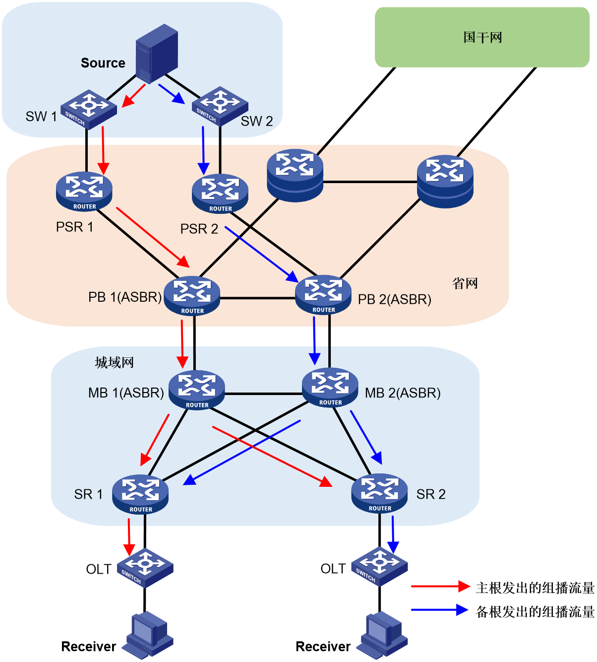
Multicast VPN scenario
The IPv6 provincial backbone network and the IPv6 metropolitan area network are in different autonomous domains. The multicast source passes through the provincial backbone network service router (PSR) to connect to the provincial backbone network router (PB), providing IPTV services from the carrier's network to home or enterprise networks to end-users in the metropolitan area. To ensure high availability (HA), a dual hot spare method is adopted. Here, PSR 1 and PSR 2 are the primary and backup routing paths for BIER respectively, and the multicast source connects with the primary and spare paths through Ethernet switches SW 1 and SW 2.
In the provincial network and metropolitan area network (MAN), BIER technology is applied. Multicast source 2 from VPN a is accessed through CE 1 in MAN AS 21. The multicast data passes through the carrier's network via MVPN, providing multicast services to multicast recipients in the same VPN a.
Figure 47 In the typical networking application of deploying BIER multicast services in MVPN.
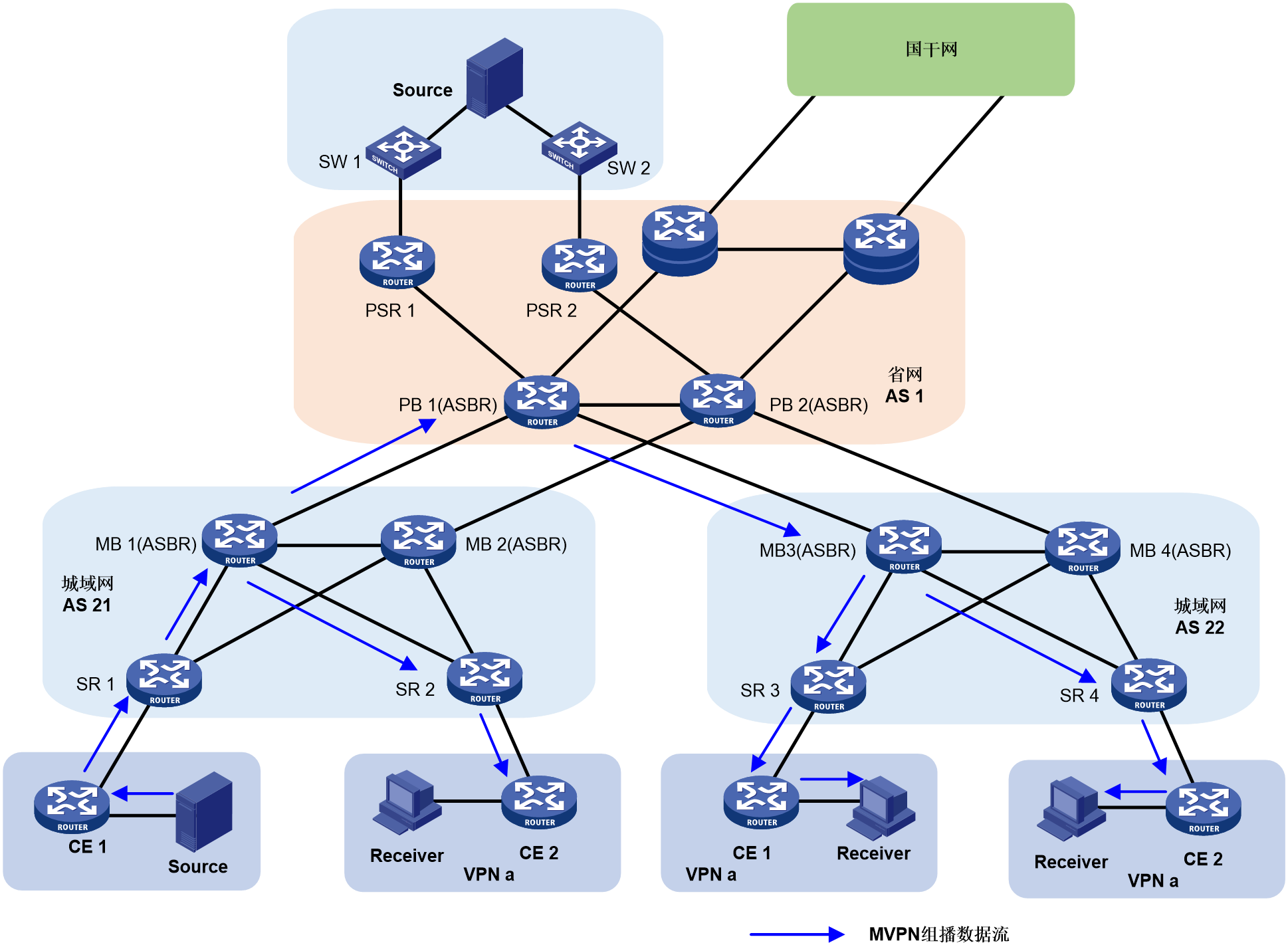
References
· China Mobile's IPv6 multicast G-BIER scheme.
· RFC8279: Utilizing Bit Index Explicit Replication (BIER) in Multicast
· RFC8296: Bit Index Explicit Replication (BIER) Encapsulation in MPLS and Non-MPLS Networks
· RFC8401: Supporting Bit Index Explicit Replication (BIER) using IS-IS protocol.
