- Released At: 18-12-2024
- Page Views:
- Downloads:
- Table of Contents
- Related Documents
-
APN6 Technology White Paper
Copyright © 2024 New H3C Technologies Co., Ltd. All rights reserved.
No part of this manual may be reproduced or transmitted in any form or by any means without prior written consent of New H3C Technologies Co., Ltd.
Except for the trademarks of New H3C Technologies Co., Ltd., any trademarks that may be mentioned in this document are the property of their respective owners.
This guide describes only the most common information for lightning protection. Some information might not be applicable to your products.
Contents
APN ID template and APN ID instance
APN ID-based traffic isolation
Using APN6 for game acceleration services
Using APN6 for SDWAN cloud private line
Overview
Technical background
The layered and decoupled design philosophy of the TCP/IP protocol stack played a crucial role in the early standardization of networks. However, as networks and applications continually evolve, a fully decoupled design is no longer suitable. The demand for network-aware applications and Application-Driven Networks (AD-NET) is becoming increasingly urgent.
· Carriers are leveraging their well-established network infrastructure to build "smart pipes."—With inherent advantages in network services, carriers are facing significant disruptions to their traditional voice, messaging, and video frequency (VF) services due to the growth of Internet companies' Over-the-top (OTT) services, which bypass carrier networks. Consequently, carriers have become mere "pipes" for bearer services. To counter this, carriers have been rapidly developing cloud services and proprietary applications in recent years. By upgrading and transforming their network infrastructure, they aim to create "smart pipes" capable of network-aware applications, offering users more precise and differentiated services.
· Ensuring critical services in industry networks—For example, video conferencing in office networks requires priority network protection to prevent video and voice services from lagging or experiencing excessive delay. Different industries and office network scenarios may use various applications for video and voice services; identification of these applications is essential for further ensuring service quality.
· Special service scenarios with clear Service Level Agreement (SLA) requirements—In scenarios such as autonomous driving, industrial control, and remote control, services have specific network SLA requirements, such as a maximum latency of 50ms and jitter not exceeding 1ms. Applications must first communicate their network quality requirements to prompt intelligent path selection and real-time service quality monitoring.
The emergence of these new requirements highlights the necessity of network-aware applications and Application-Driven Networks (AD-NET).
APN6+ technical benefits
About APN6
Application-aware IPv6 Networking (APN6) is a new network architecture designed to provide differentiated fine-grained network services for applications. It enables network devices to identify applications and their network requirements by conveying APN attributes in the extension header space in IPv6 packets.
· APN ID—APN service identifier for an application. The IPv6 packets on an APN6 network must convey this information.
· APN parameters—Network performance requirements of the application, such as bandwidth, latency, jitter, and packet loss. This information is optional for IPv6 packets on the APN6 network.
By conveying APN attributes in the IPv6 extension header space, APN6 recouples the network and application attributes that are decoupled to different layers of the TCP/IP protocol stack.
· From the perspective of the network, the network devices can obtain the network performance requirements of applications from IPv6 and provide services as required.
· From the perspective of applications, the programmable space of IPv6 packets is open. Applications can define the APN ID and APN parameters as needed.
The main advantages and value of APN6 include the following aspects:
· Application information is straightforward.
· High scalability.
· Compatibility with various IPv6+ technologies.
Application information is straightforward
Traditional application packets lack information about the application's requirements for network quality, and the identification of application information is unclear. Typically, identification of application or user business flows is achieved through the following two methods:
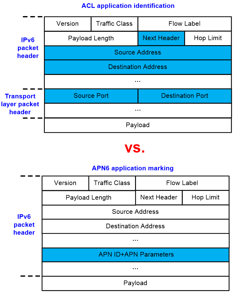
· Devices use ACLs to resolve the quintuple information within packets to identify the associated application and user. This method consumes substantial hardware ACL resources and cannot meet the requirements for identifying a vast number of applications.
· Deploying deep packet inspection (DPI), which analyzes the contents of IP packets to identify the type of flow based on signature searches or statistical behavior of the service. This method incurs additional operational overhead and might raise security and privacy concerns.
As shown in Figure 1, APN6 simplifies operational deployment and reduces hardware ACL resource consumption by directly encapsulating application information into the IPv6 packet header, unlike traditional ACL rules that identify the application and user of a packet. APN6 embeds application information directly into the IPv6 packet header, eliminating the need for devices to resolve and match fields like the 5-tuple in the packet. Devices only need to retrieve information from the IPv6 extension header to obtain application ID and the application's network quality requirements. This streamlines deployment and conserves hardware ACL resources. Additionally, APN6 does not analyze the payload of IP packets, preventing the risk of information leakage. Therefore, the APN6 network schema is more direct and well-suited for applications that require network awareness.
Figure 1 Application identification by ACL and application identification by APN6
High scalability
The expansion header in IPv6 provides programmable space, allowing for carrying richer APN6 application information based on requirements, offering strong expandability.
As shown in Figure 2, the IETF draft draft-li-apn-ipv6-encap describes the positions that can carry application information, including the hop-by-hop option in the IPv6 extension header, the message header HBH (Hop-by-Hop Options Header), the destination option message header DOH (Destination Options Header), and the route message header SRH (Segment Routing Header). All these extension headers provide programmable space and can be expanded to carry application information.
Comware carries the application information of APN6 in DOH.
Figure 2 IPv6 expansion headers that provide a programmable space

Compatibility with various IPv6+ technologies
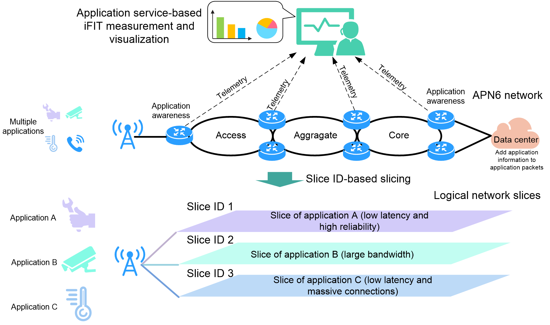
APN6 is compatible with various network requirements, such as SRv6 network slicing, deterministic networking, SRv6 SFC, and iFIT. With these technologies applied, an APN6 network can provide more granular network services. As shown in Figure 3, with SRv6 network slicing applied, an APN6 network can provide dedicated slice networks for different applications, ensuring exclusive resource allocation. With iFIT applied, it can provide application-level performance policies, fault identification, and visualized Ops in real time.
Figure 3 SRv6 network slicing and iFIT application in an APN6 network
How APN6 works
This chapter describes the basic principles of APN6, including its network architecture, the generation of APN ID identifiers, the packet encapsulation format, and the forwarding policies for application packets, based on IETF drafts such as draft-li-apn-framework and draft-li-apn-header.
APN6 network architecture
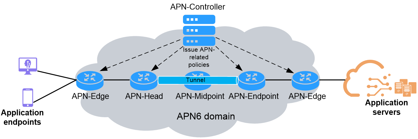
As shown in Figure 4, an APN6 domain in the network is a set of network devices that provide application-aware services based on the IPv6 packets encapsulated with APN attributes, which are called APN6 packets. An APN6 domain has the following node roles:
· APN-Edge—Connects application endpoints or servers to the APN6 domain. APN-Edge nodes add APN attributes to packets when they enter the APN6 domain and remove APN attributes from packets when they leave the APN6 domain. APN-Edge nodes add APN attributes based on the application attributes in QoS policies, such as the IP five-tuple, outer SVLAN, and inner C-VLAN.
· APN-Head—Establishes tunnels with APN-Endpoint nodes to transport application workloads over the APN6 domain to their destination. An APN6 network should have a set of tunnels between APN-Head and APN-Endpoint nodes to meet different service level agreements (SLAs). APN-Head nodes steer application workloads to SLA-compliant tunnels based on their APN attributes. APN-Edge and APN-Head nodes can be collocated on the same device.
· APN-Midpoint—APN6 transit nodes. They forward application workloads and provide value-added services such as iFIT and SRv6 SFC based on the application attribute in the APN6 packets.
· APN-Endpoint—Destination node of a tunnel for APN6 packets. An APN-Endpoint node decapsulates the outer header of tunneled APN6 packets. If the outer header of an APN6 packet contains APN attributes, the APN-Endpoint node removes the APN attributes. If the APN6 attributes are conveyed in the inner packet, the APN-Endpoint node continue to forward the APN6 packet. APN-Edge and APN-Endpoint nodes can be collocated on the same device.
· APN-Controller—Controller of the APN6 network. It plans and maintains APN ID and APN parameter information, defines and deploys forwarding and marking policies related to APN IDs.
¡ For APN-Edge nodes, the APN-Controller deploys APN ID marking policies to map the application to an APN ID based on the IP 5-tuple, outer SVLAN, or inner C-VLAN.
¡ For APN-Head nodes, the APN-Controller deploys forwarding policies to establish mappings between APN IDs and forwarding paths. Then, the APN-Head nodes steer APN packets to an appropriate candidate forwarding path based on the mappings.
Figure 4 APN6 network architecture and device roles
Depending on the role of the node that generates APN attributes, the following solutions are available to build an APN6 network:
· Application-side solution—The application endpoints or servers generate and encapsulate the APN attributes (APN ID and APN parameters) in packets. This solution requires that the application endpoints and servers can recognize different applications. In addition, both the network and applications must be planned and managed by the same organization, so the network devices can trust the APN attributes generated on the application side.
· Network-side solution—The APN-Edge nodes generate and encapsulate the APN attributes (APN ID and APN parameters) in packets. When a packet arrives, an APN-Edge node identifies its packet type and encapsulates its matching APN attributes. This solution does not require application-side support. The network operators can plan and deploy the APN6 network uniformly, with ease.
APN ID and packet format
APN6 conveys the application attribute in the APN header in the APN option. According to the RFC draft draft-li-apn-header, the APN option is located in the Destination Option Header (DOH) of IPv6 and has a typical Type-Length-Value structure, as shown in Figure 5. In IPv6 encapsulation, the DOH that contains the APN option is placed next to the Segment Routing Header (SRH). When of packets the configuration items is used in conjunction with the iFIT feature, an IPv6 packet might have two DOH headers. In this situation, the DOH next to the SRH is accessible only to the destination node. Any other nodes along the path cannot access this header.
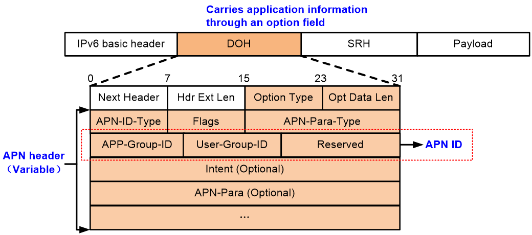
The DOH that contains the APN option includes the following sections:
· Next Header—8 bits, type of the next header to the DOH.
· Hdr Ext Len—8 bits, length of the DOH in units of 8 bytes, excluding the first 8 bytes.
· Option Type—8 bits, type of the option. The value for the APN Header is 0x13.
· Opt Data Len—8 bits, length of the APN Header.
· APN Header—Variable in length. This section contains the application attribute, including the APN ID and the APN parameters.
The APN Header contains the following fields:
· APN-ID-Type—8 bits, type of the APN ID. The following types of APN IDs are available:
¡ Type 1 APN ID—The type value for this type of APN ID is 1. A type-1 APN ID occupies 4 bytes.
¡ Type 2 APN ID—The type value for this type of APN ID is 2. A type-2 APN ID occupies 8 bytes.
¡ Type 3 APN ID—The type value for this type of APN ID is 3. A type-3 APN ID occupies 16 bytes.
· Flags—8 bits. This field is undefined.
· APN-Para-Type—16 bits. This field indicates types of network performance parameters included in the APN parameters, which can be any combinations of bandwidth, delay, jitter, and packet loss.
· APN ID—Variable in length. An APN ID contains the following segments:
¡ APP-Group-ID—Identifier of an application group.
¡ User-Group-ID—Identifier of a user group.
¡ Reserved—A field reserved for future use.
· Intent (Optional)—An optional field of 32 bits. This field contains the intent requirements proposed by the application to the network.
· APN-Para (Optional)—An optional field of 32 bits. This field contains values for network performance parameters. Each parameter uses 4 bytes.
APN ID template and APN ID instance
The system enables flexible generation of APN IDs based on APN ID templates and APN ID instances.
· APN ID template—Enables creation of flexible structured APN ID plans. As shown in Figure 6, you use an APN ID template to specify the total length of the APN ID space and the maximum lengths of the APP-Group-ID and User-Group-ID spaces. The length of the Reserved field is the total length of the APN ID space minus the total maximum lengths of the APP-Group-ID and User-Group-ID spaces. To represent a sequence of applications and users, divide the APP-Group-ID and User-Group-ID spaces into variable-length fields, respectively. In the template, assign each field an index to identify their order in their respective space, with the lowest index for the leftmost field.
¡ A field in the APP-Group-ID space represents an application or service and is called an APP-Group-ID field.
¡ A field in the User-Group-ID space represents a user and is called a User-Group-ID field.
Figure 6 APN ID template structure

· APN ID instance—Each APN ID instance represents an APN ID. To generate a concrete APN ID, you apply an API ID template to an APN ID instance, and then assign values to the APP-Group-ID and User-Group-ID fields in the template.
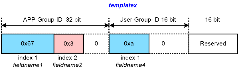
Figure 7 shows an APN ID generation example based on an APN ID template named templatex. In this template, the total length of the APN ID space is set to 64 bits. The maximum lengths for the APP-Group-ID and User-Group-ID spaces are set to 32 bits and 16 bits, respectively. The Reserved field is 16 bits. The template defines the following fields:
· An 8-bit APP-Group-ID field named fieldname1 at index 1.
· A 4-bit APP-Group-ID field named fieldname2 at index 2.
· A 4-bit User-Group-ID field named fieldname4 at index 1.
Apply this APN ID template to an APN instance and assign values to the fields defined in the template as follows:
· Set the fieldname1 field in the APP-Group-ID space to 103 (0x67 in hexadecimal notation).
· Set the fieldname2 field in the APP-Group-ID space to 3 (0x3 in hexadecimal notation).
· Set the fieldname4 field in the User-Group-ID space to 10 (0xa in hexadecimal notation).
Figure 7 Schematic diagram for generating an APN ID
Packet forwarding in APN6
APN ID-based traffic steering
To steer traffic based on APN ID, first the service traffic must be steered into the SRv6 TE Policy group. Within this group, establish mappings between APN ID and SRv6 TE Policy or SRv6 BE. When traffic is forwarded in the SRv6 TE Policy group, the system searches for an SRv6 TE Policy or SRv6 BE policy that matches the APN ID carried by the traffic. It then forwards the traffic according to the matched SRv6 TE Policy path or by the SRv6 BE method.
As shown in Figure 8, to steer traffic based on APN ID, complete the following configuration:
· Configure an SRv6 TE Policy group on Device A with an egress node of Device H and an Endpoint of 5::5. The group ID of this SRv6 TE Policy group is 111.
· Configure two SRv6 TE Policies on Device A, SRv6 TE Policy 1 and SRv6 TE Policy 2, both leading to Device H. These policies share the same Endpoint with the SRv6 TE Policy group 111, making them part of this group. SRv6 TE Policy 1 and SRv6 TE Policy 2 have different forwarding paths and their network quality varies.
· Configure QoS on Device A and apply it to the inbound orientation of the interface connecting to private network VPN 1. Use 5-tuple or VLAN information to mark and encapsulate application information for private network packets.
Figure 8 Diagram for APN ID-based traffic forwarding
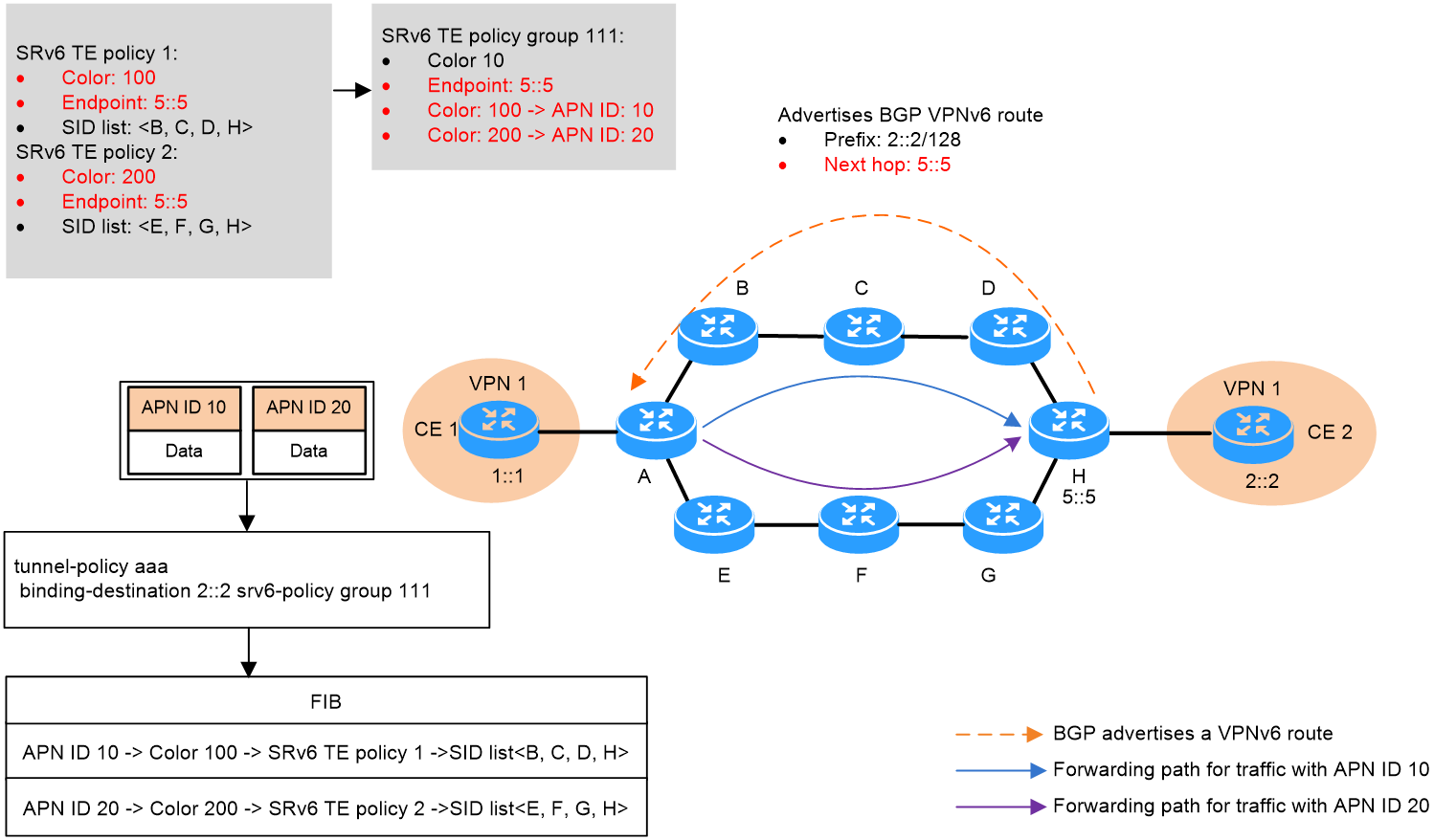
Take IPv6 L3VPN over SRv6 TE Policy networking as an example. APN Id-based traffic steering operates as follows:
1. In the SRv6 TE policy group, specify the forward type as APN ID-based forwarding and create mappings between APN IDs and forwarding policies. The device supports the following types of mappings:
¡ Color-to-APN ID mapping—Device A steers packets with a specific APN ID to the SRv6 TE policy associated with the color attribute value mapped to that VPN ID. As shown in figure, APN ID instance a is mapped to SRv6 TE Policy 1, and APN ID instance b is mapped to SRv6 TE Policy 2. For more information about the forwarding process, see “0Forwarding of packets that carry an APN ID.”
¡ In SRv6 BE mode, Device A encapsulates the packets with a new IPv6 header. The destination address in the IPv6 header is the SID assigned by the egress node of the SRv6 TE policy group to VPN to a VPN instance. Then, the device looks up the IPv6 routing table for a matching route and forwards the packets through the output interface.
2. On device A, configure a tunneling policy to bind the private network route 2::2/128 with the SRv6 TE Policy group 111. When device A receives traffic destined for the private network route 2::2/128, it routes the traffic through the SRv6 TE Policy group. Device A selects the forwarding method based on the APN ID carried by the traffic packets.
For APN ID-based traffic forwarding, compared with SRv6 BE forwarding, SRv6 TE policy forwarding has controllable paths and provides higher availability, and can be combined with iFIT measurement methods to detect the network quality of end-to-end fixed forwarding paths. As a best practice, use SRv6 TE policy tunnels to forward traffic for critical application services
Forwarding of packets that carry an APN ID
As shown in Figure 9, device A acts as both an APN6 edge device and an APN6 head-end node, and device D acts as an APN6 edge device and an APN6 tail node. Both device B and device C operate as APN6 intermediate nodes.
Take the forwarding of packets carrying the APN ID in an SRv6 TE Policy tunnel as an example. The packet forwarding process is as follows:
Figure 9 APN ID-based packet forwarding
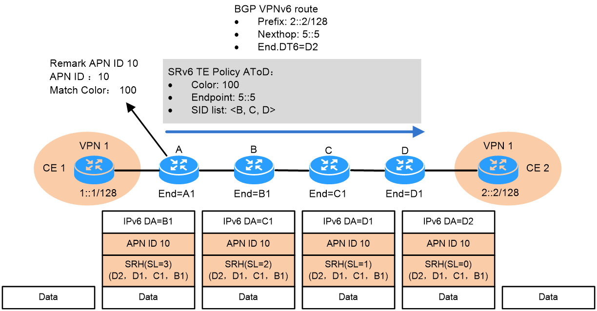
1. CE 1 sends a private network service packet to CE 2, with the destination address 2::2. CE 1 forwards the private network packet to Device A based on the routing table.
2. After Device A receives the private network packet through the private network interface bound to VPN 1, it adds a DOH extension header to the packet that meets the traffic classification rule according to the QoS policy and includes the identifier of APN ID instance a, with a value of 0x1. Device A then looks up the private network routing table of VPN 1 and finds that the next hop for the 2::2/128 private network route is the address 5::5 of device D's Loopback0 interface, with the private network's End.DT6 SID identified as D2.
3. Device A steers traffic into the SRv6 TE Policy group according to the tunneling policy bound to the private network routing. Within the SRv6 TE Policy group, packets with APN ID 0x1 are forwarded into SRv6 TE Policy AtoD. Device A encapsulates a new IPv6 header and SRH header for the packets according to SRv6 TE Policy AtoD, and inserts the DOH extension header carrying APN ID 0x1 into the new IPv6 header. The SRH header carries a SID list of {D2, D1, C1, B1}, where D2 is the private network's End.DT6 SID, D1 is Device D's End SID, C1 is Device C's End SID, and B1 is Device B's End SID. At this point, SL=3, which indicates the destination address in the IPv6 header is SRH[3], which is B1. Device A then forwards the encapsulated packet to Device B according to the IPv6 routing table.
4. After device B receives the packet and identifies the destination address as the local SID, it detects that the SL in the SRH is not zero. It then decrements SL by 1, updates the IPv6 packet header's destination address to SRH[2], which is C1, and then transmits the packet to Device C.
5. After device C receives the packet and identifies the destination address as the local SID, it detects that the SL in the SRH is not zero. It then decrements SL by 1, updates the IPv6 packet header's destination address to SRH[1], which is D1, and then transmits the packet to Device D.
6. After Device D receives the packet and identifies the destination address as Local SID, it detects that the SL in SRH is not zero. It then decrements the SL by 1 and updates the IPv6 message header's destination address to SRH[0], which is D2, which is Device D's local SID. Following the actions for End.DT6 SID, Device D decapsulates the packet, deletes the DOH and SRH, and looks up the VPN 1 private network routing table to transmit the original packet to CE 2.
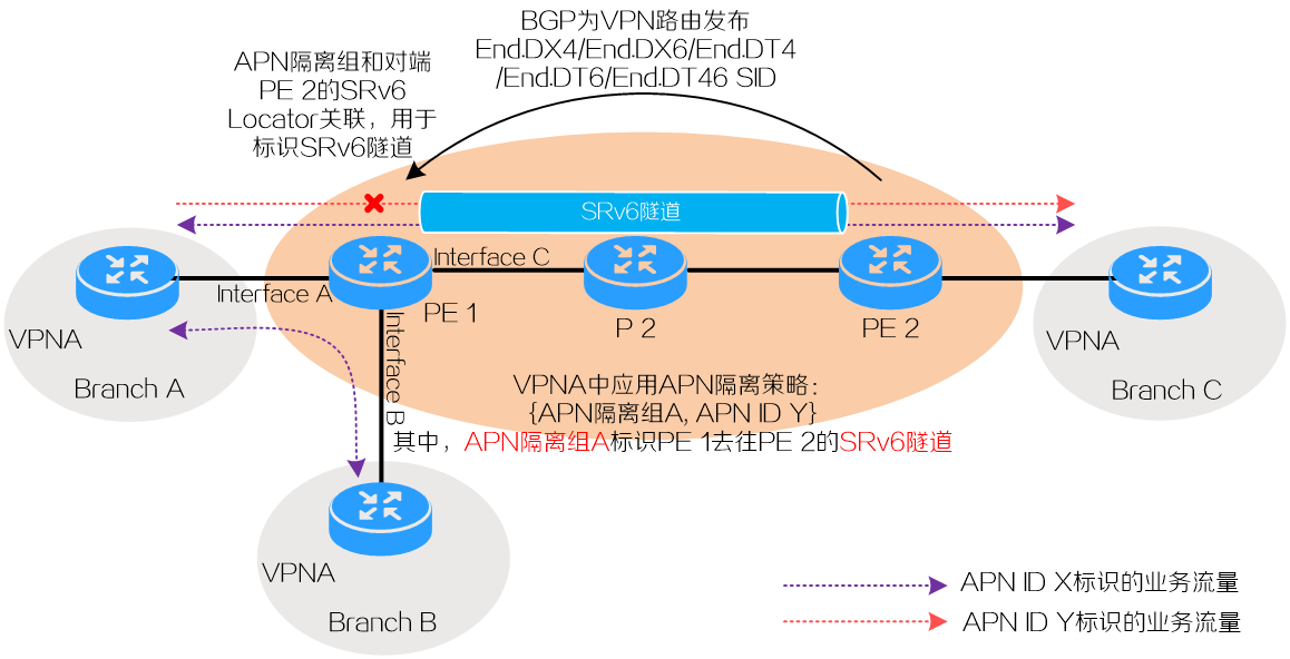
APN ID-based traffic isolation
About APN ID-based traffic isolation
In an APN6 network, a VPN might transport different types of services between different branch sites, with each service flow identified by a unique APN ID. APN ID-based traffic isolation enables you to block a service flow identified by an APN ID between two sites within the VPN, while allowing other service flows to be forwarded.
Basic concepts
· APN isolation group—Contains the outgoing interfaces or tunnels for traffic from one branch site to another within the same VPN instance.
· APN isolation policy—Contains APN isolation rules that associate APN ID instances with APN isolate groups to prevent a rule matching service flow from reaching the interfaces or tunnels specified in the matching APN isolation group.
APN ID-based mechanism to prevent service flows from reaching an interface
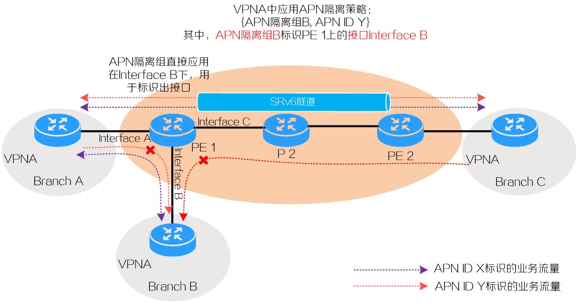
Take the network in Figure 10 for example. This network can be an IP L3VPN over SRv6 or EVPN L3VPN over SRv6 network. On this network, Branch A and B connect to Interface A and Interface B of PE 1, respectively. Branch C connects to PE 2. PE 1 and PE 2 are connected using an SRv6 tunnel. Deploy a VPN on the network to transport traffic between Branches A, B, and C. For example, create VPN instance VPNA on PE 1 and bind Interface A and Interface B to the instance. This VPN instance transports two types of service flows, which are identified by APN ID instances X and Y.
1. Create APN isolation group B, and then assign Interface B to the group by specifying the group on the interface.
2. Configure an APN isolation policy and apply it to VPN instance VPNA to prevent traffic identified by APN ID Y from reaching Interface B. For this purpose, create a rule in the policy to associate APN ID Y with APN isolation group B, which contains Interface B.
When a packet from VPNA arrives, PE 1 obtains its APN ID, identifies its outgoing interface or tunnel, and then uses this information to search the APN isolation policy. If a matching APN isolation rule is found, the device does not forward the traffic to the outgoing interface. If the packet does not match any isolation rule, the device forwards the packet out of the interface. In this example, the isolation policy prevents PE 1 from forwarding traffic identified by APN ID Y out of Interface B to reach Branch B. This blocks the service traffic for APN ID Y between Branch A and Branch B, as well as between Branch C and Branch B.
|
|
CAUTION: To prevent service flows from reaching a private network interface in an APN isolation group, you must bind that interface to a VPN instance. If you assign an interface to an APN isolation group without binding that interface to a VPN instance, the traffic isolation configuration cannot take effect. |
Figure 10 APN ID-based prevention of service flows from reaching an interface
APN ID-based mechanism to prevent service flows from reaching a tunnel
Take the network in Figure 11 for example. This network can be an IP L3VPN over SRv6 or EVPN L3VPN over SRv6 network. On this network, Branch A and B connect to Interface A and Interface B of PE 1, respectively. Branch C connects to PE 2. PE 1 and PE 2 are connected using an SRv6 tunnel. Deploy a VPN on the network to transport traffic between Branches A, B, and C. For example, create VPN instance VPNA on PE 1 and bind Interface A and Interface B to the instance. This VPN instance transports two types of service flows, which are identified by APN ID instances X and Y.
1. On PE 2, allocate an SRv6 SID for the private VPNA route to Branch C from a SRv6 locator and advertise the SID to PE 1. Then, PE 1 does recursive routing to forward the traffic that matches the private VPNA route to Branch C through the SRv6 tunnel.
2. On PE 1, define a mapping for APN instance VPNA, APN isolation group A, and the SRv6 locator. This mapping associates APN isolation group A and the SRv6 tunnel for a VPNA packet sent from PE 1 to PE 2, if its SID matches the specified SRv6 locator.
3. Apply the APN isolation policy to VPN instance VPNA to prevent traffic identified by APN ID Y from reaching the SRv6 tunnel.
4. When a packet from VPNA arrives, PE 1 obtains its APN ID, identifies its outgoing interface or tunnel, and then uses this information to search the APN isolation policy. If a matching APN isolation rule is found, the device does not forward the traffic to the outgoing interface or tunnel. If the packet does not match any isolation rule, the device forwards the packet out of the interface. In this example, the isolation policy prevents PE 1 from forwarding traffic identified by APN ID Y out of the SRv6 tunnel established with PE 2 to reach Branch C. This blocks the service traffic for APN ID Y between Branch A and Branch C.
Figure 11 APN ID-based prevention of service flows from reaching a tunnel
APN6 application
Using APN6 for game acceleration services
The draft-zhang-apn-acceleration-usecase proposes an APN6 application solution for latency-sensitive gaming services. Typically, international multiplayer competitive games require a latency under 30ms, and in major e-sports events, the latency must be even lower than 10ms. Gaming terminals must connect to domestic gaming operators' exit acceleration routes through carrier devices, then access overseas data servers via international POP nodes. This DF process is lengthy, and traditional carriers cannot provide gamers with stable, low-latency access services.
As shown in Figure 12, carriers and game operators can collaborate through the COD to deploy APN6 networks. They can precisely identify datagrams of specific games on users' access devices and provide gamers with stable, low-latency acceleration tunnels. This significantly enhances the gaming experience and expands the scope of value-added services for carriers.
Figure 12 APN6 application in the game acceleration service
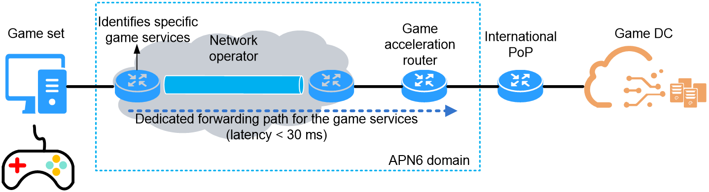
Using APN6 in the gaming acceleration service offers the following benefits:
· For gamers—Achieve stable acceleration delay to enhance the gaming experience.
· For carriers—Expand the scope of value-added services to create new revenue streams.
· For game operators—Improve player retention and game satisfaction.
Using APN6 for SDWAN cloud private line
Corporate branch sites in different cities use dedicated cloud access to connect to cloud services. Dedicated lines must traverse multiple autonomous systems managed by different personnel. The inability to share route information between autonomous systems makes unified end-to-end path planning difficult. This poses a challenge to quality assurance for critical business operations on dedicated lines.
As shown in Figure 13, by deploying APN6 in the network, enterprises can encapsulate application information such as APN ID directly at the edge CPE for critical business packets. This allows devices in different ASs to access the application information of critical business packets.
Figure 13 APN6 application in SDWAN cloud private line
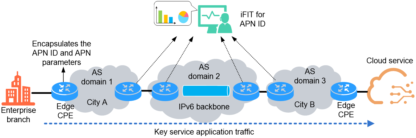
APN6 application in SDWAN cloud dedicated line offers the following value to enterprise customers:
· Reduce CPE stress—CPE devices do not need deployment of deep packet inspection (DPI) to identify the application type of packets.
· Implement precise application-level network operations and maintenance—By integrating iFIT measurements, you can accurately capture the application traffic of critical business services from massive traffic for targeted measurement and monitoring.
· Ensure network quality at the application level with precision—Devices within different ASs can steer critical business application traffic to specific forwarding paths based on application information, maintaining network quality.
References
· draft-li-apn-framework
· draft-li-apn-header
· draft-zhang-apn-acceleration-usecase
· draft-yang-apn-sd-wan-usecase
