- Table of Contents
| Title | Size | Download |
|---|---|---|
| 01-Text | 3.50 MB |
Contents
Configure external network settings
Configuring the interface mode
Configure user-defined protocol port numbers
View DHCPv6 client information
Configure network behavior management
Configure bandwidth management
Configure network behavior management
Network connection limit number
MAC allowlist and denylist management
Configure the local DNS service
Collect diagnostic information
About this guide
|
If you want… |
You can check… |
|
The general form, business features, or its positioning in actual network applications |
Product overview |
|
To manage the device by building a Web environment, while also wanting to view the device's operating status and the basic function configuration wizard |
Login to device and system information |
|
To view the device port status, traffic conditions of each link, and terminal traffic usage |
System monitoring |
|
To configure WAN, LAN, VLAN, and other related functions through the Web setup page, as well as to set advanced business functions of the device, such as virtual servers and one to one NAT mapping |
Network settings |
|
To manage Internet behavior functions such as bandwidth management, URL control, and application control through the Web setup page |
Internet behavior management |
|
To implement security settings for the device and network environment through the Web setup page, such as firewall, connection limits, MAC address filtering, and ARP security |
Network security |
|
To enable IPSec VPN and L2TP VPN functions through the Web setup page |
Virtual private network |
|
To set static DNS, dynamic DNS, static routes, and other functions through the Web setup page |
Advanced options |
|
To perform maintenance management on the device through the Web setup page, such as software upgrades |
System tools |
Product overview
Introduction
H3C Aolynk UR series enterprise-class routers are primarily suitable for small and medium-sized enterprises and small network environments such as villas and large apartments that require high-speed wired and wireless access. This series of routers integrates routing, switching, AC, firewall, and PoE functions, significantly simplifying network deployment.
Features
The device offers a rich set of software features that help you quickly configure various functional requirements. The main supported features are as follows.
· Multi-WAN Load Balancing
The device supports load balancing across multiple WAN ports, meeting the networking needs of enterprises with multiple carrier access. Users can allocate network traffic based on the actual bandwidth of the links, fully utilize bandwidth, and ensure network stability even when one of the carrier links fails, as the other links will still function normally.
· Enterprise-Class VPN Functionality
The device supports IPSec VPN and L2TP VPN, making it convenient for enterprises to build virtual private networks over the Internet.
· Configure network behavior management
The device supports URL filtering, allowing users to restrict access to custom web pages through keyword fuzzy matching.
· High-Performance Firewall
The built-in high-performance firewall can protect against various external professional attack methods, such as DDoS attacks and port scanning.
The device includes an internal network anomaly traffic protection module that inspects traffic from each host within the local area network (LAN) and processes it based on the selected IP rating (supporting high, medium, and low levels), ensuring that the network continues to function normally during such anomalous attacks.
· Network Traffic Rate Limiting
With IP-based network traffic rate limiting, you can effectively control the upstream/downstream traffic of designated users, limiting excessive bandwidth consumption by P2P software. For P2P download packets that consume significant bandwidth, you can enable the rate-limiting channel feature to restrict their bandwidth; for interactive application traffic that requires guaranteed latency, you can enable the green channel feature to ensure its bandwidth.
· Security Policy Protection
The device supports firewall filtering policies based on source and destination addresses and ports. By setting outbound and inbound communication policies, you can allow or prohibit specific application data flows through the router; at the same time, it supports policy configuration based on user groups and time periods for refined management.
Logging in to the device
|
|
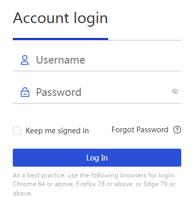
NOTE: · As a best practice, use Chrome version 64 or higher, Firefox version 78 or higher, or Edge version 79 or higher to access the web management page. · If this is your first time logging into the device, after entering
the device management address, you will default to the UWEB network
deployment page. After completing the network deployment, click the UWEB page
in the top left corner " · If the device's self-organizing network feature has been disabled, entering the device management address will default to the local management login page. |
The steps to log into the device are as follows:
|
1. Connect the PC to the device's LAN interface. 2. Configure the PC to automatically obtain an IP address. 3. Check the proxy server settings on the PC. If the PC currently uses a proxy server to access the Internet, you must first disable the proxy service. 4. Run the web browser. Please enter the management address displayed on the device's nameplate in the browser's address bar and press carriage return (CR). 5. As shown in the figure below, enter the administrator username and password (both default to admin) in the pop-up window. 6. Click the <Login> button. |
|
System information
Introduction
The system information will display the device's operating status, basic function configuration wizard, and technical support information.
System information
CPU usage and memory usage
Page Wizard: System Information → System Information
|
Check CPU usage and memory usage |
|
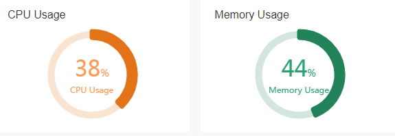
The meanings of each parameter on the page are shown in the table below.
Table 1 Parameter description
|
Parameter |
Description |
|
CPU usage |
Current CPU usage of the device. Click the "CPU Usage" section at the top of the page to view the current and average CPU usage. |
|
Memory usage |
Current memory usage of the device. Click the "Memory Usage" section at the top of the page to view the current and average memory usage. |
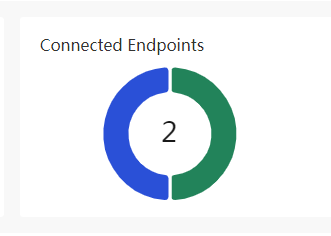
Endpoints
Page Wizard: System Information → System Information
|
View the relevant information of the access terminal |
|
The meanings of each parameter on the page are shown in the table below.
Table 2 Parameter description
|
Parameter |
Description |
|
Endpoints |
For information related to terminal access within the local area network (LAN), · Real-time traffic ranking TOP 5 · Number of onlink hosts and the number of network connections for onlink hosts · Onlink host information table, which includes terminal IP address, terminal name, number of network connections, access method, interface, terminal MAC address, and other information |
|
Real-time traffic ranking TOP 5 |
The TOP 5 traffic usage of access terminals. |
|
Number of onlink hosts |
The number of onlink hosts within the local area network (LAN) |
|
Number of network connections for onlink hosts |
The number of sessions for all onlink hosts connecting to the network within the local area network (LAN) |
|
Terminal IP address |
The IP address of the access terminal |
|
Terminal name |
The username of the access terminal |
|
Number of network connections |
The number of sessions for the terminal connecting to the network, mainly divided into: · If the terminal transmits TCP packets, the page displays the number of TCP packet network connections · If the terminal transmits UDP packets, the page displays the number of UDP packet network connections · If the terminal transmits other packets, the page displays the number of other packet network connections |
|
Access method |
The method used for terminal access to the network, mainly divided into: · Static IP: The terminal accesses the network using a static IP address · DHCP Allocation: The terminal accesses the network using an IP address allocated by the device's DHCP · PORTAL: An authentication method where the terminal accesses the network using Portal authentication |
|
Ports |
The device interface used for terminal access to the network, such as VLAN1 |
|
Endpoint MAC address |
MAC address of the access terminal |
|
Uplink Flow Rate |
Upstream traffic rate of the access terminal |
|
Downlink Flow Rate |
Downstream traffic rate of the access terminal |
|
Onlink Duration |
Duration of terminal access to the network |
|
Traffic details |
Detailed information about the traffic usage of this terminal |
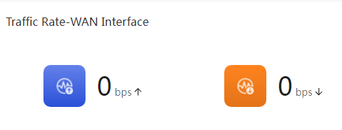
Internet Traffic
This displays information related to the device's Internet traffic, such as: average upstream speed over the last 5 minutes, average downstream speed over the last 5 minutes, the status of the WAN interface, and Internet parameters.
Page Wizard: System Information → System Information
|
You can view relevant information about NetStream traffic. |
|
The meanings of each parameter on the page are shown in the table below.
Table 3 Parameter description
|
Parameter |
Description |
|
NetStream traffic |
To view the NetStream traffic status of the device, click on the "NetStream traffic" section at the top of the page to see the traffic information and interface status for each WAN interface. |
|
Average upload speed in the last 5 minutes |
The average upload speed for the WAN interface over the last 5 minutes, measured in bps. |
|
Average download speed in the last 5 minutes |
The average download speed for the WAN interface over the last 5 minutes, measured in bps. |
|
Monitor period |
Select the cycle for monitoring the traffic of the specified WAN interface, including: every 1 hour, every 1 day, every 1 month. |
|
Ports |
The interface through which the device accesses the wide area network (WAN). |
|
MAC |
The MAC address used by the device to access the wide area network (WAN). |
|
Connection Type |
The actual way users access the internet, with options including: · PPPoE: Broadband dial-up internet access method. · DHCP: Internet access method that automatically obtains an address from a DHCP server to connect to the wide area network (WAN). · Static address: Internet access method that uses a static address provided by the carrier to connect to the wide area network (WAN). |
|
Username |
The username used for authentication. This parameter is provided by the carrier. When the connection mode is set to PPPoE, this parameter must be configured. |
|
IP address |
The IP address through which the device accesses the wide area network (WAN). |
|
Subnet mask |
The mask or mask length of the IP address. |
|
Gateway |
The gateway address through which the device accesses the wide area network (WAN). |
|
DNS1 and DNS2 |
The DNS server addresses for the device accessing the wide area network (WAN). DNS1 is prioritized for domain name resolution; if resolution fails, DNS2 will be used for domain name resolution. |
|
MTU |
The size of the MTU (Maximum Transmission Unit) allowed for the device interface. Measured in bytes. |
|
Status |
The connection status of the device interface to the wide area network (WAN), mainly categorized as: · Onlink: This interface is connected to the wide area network (WAN). · Offlink: This interface is not connected to the wide area network (WAN). |
|
Connection Time |
The duration for which this interface has been connected to the wide area network (WAN). |
System information
This displays the device's system time and product model information.
Page Wizard: System Information → System Information
|
In the “system time” section, you can view the system time and run time; in the “product model” section, you can find information such as the product model, serial number, Boot ROM version, hardware version, and software version. |
|

The meanings of each parameter on the page are shown in the table below.
Table 4 Parameter description
|
Item |
Description |
|
System time |
Display the device's system time |
|
Uptime |
Display the device's run time |
|
Switch model |
Display product model information |
|
Serial number |
Display the device's serial number information |
|
Boot ROM version |
Display the device's Boot ROM version information; click "Show more..." to view |
|
Hardware Version |
Display the device's hardware version information; click "Show more..." to view |
|
Software version |
Display the device's software version information |
Port Status
This shows the usage status of the WAN and LAN ports.
Page Wizard: System Information → System Information
|
In the "Port Status" section, click the port icon to access the WAN or LAN configuration page. |
· WAN configuration interface:
· LAN configuration interface:
|
The meanings of each parameter on the page are shown in the table below.
Table 5 Parameter description
|
Item |
Description |
|
Port Status |
The current usage status of the WAN and LAN ports. In the "Port Status" section, click the port icon to access the WAN or LAN configuration page. |
Self-organizing network
Please be cautious when disabling the self-organizing network feature; once disabled, the overall network management function will not be available. To re-enable it, please restore the device to factory settings.
After disabling the self-organizing network feature, the web management page will enter local management mode, and the device will operate in standalone mode.
After enabling the self-organizing network
feature, the homepage will display the self-organizing network role; at the
same time, the web management page can switch between overall network
management and local management pages. You need to click the current management
mode in the top left corner of the web management page and select the mode to
switch in the dropdown menu![]() or
or![]() .
.
· The overall network management mode allows you to view management information for all devices in the network and configure all devices from a network-wide perspective;
· The local management mode is specifically for configuring the currently logged-in device.

Flash usage
Usage of storage media's memory space.
Page Wizard: System Information → System Information
|
You can view the usage rate of memory space on Flash. |
|

The meanings of each parameter on the page are shown in the table below.
Table 6 Parameter description
|
Parameter |
Description |
|
Storage media |
Current usage status of the device's memory space. In the lower right section of the page, you can view the usage rate of the storage media. |
Quick navigation
Quick navigation helps users quickly configure the network.
|
On the quick navigation page, click the link corresponding to the function as needed. |
|
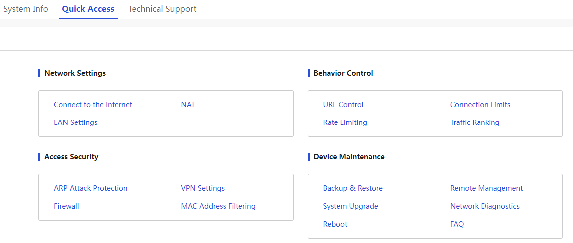
The meanings of Parameter on the page are shown in the table below.
Table 7 Parameter description
|
Parameter |
Description |
|
Network access configuration |
The configuration function for the device to access the internet mainly includes: · Connect to the Internet: Click "Connect to the Internet," and the page will automatically go to the connect to the internet page. · Local Area Network (LAN) settings: Click "Local Area Network (LAN) Settings," and the page will automatically go to the LAN settings page. · NAT configuration: Click "NAT Configuration," and the page will automatically go to the LAN settings page. |
|
Internet access |
The function of internet behavior management for the device mainly includes: · URL control: Click "URL Control," and the page will automatically go to the URL control page for internet behavior management. · Bandwidth limiting: Click "Bandwidth Limiting," and the page will automatically go to the IP bandwidth management page. · Connection limit: Click "Connection Limit," and the page will automatically go to the connection limit page. · Traffic measurement ranking: Click "Traffic Measurement Ranking," and the page will automatically go to the traffic ranking page. |
|
Access security |
The security functions for user access networks mainly include: · ARP security: Click "ARP Security," and the page will automatically go to the ARP security page. · Firewall: Click "Firewall," and the page will automatically go to the firewall page. · VPN settings: Click "VPN Settings," and the page will automatically go to the IPsec VPN page. · MAC address filtering: Click "MAC Address Filtering," and the page will automatically go to the MAC address filtering page. |
|
Device Maintenance |
The operational maintenance functions of the device mainly include: · Configuration management: Click the "Configuration Management" link, and the page will automatically go to the configuration management page. · System upgrade: Click the "System Upgrade" link, and the page will automatically go to the system upgrade page. · Restart: Click the "Restart" link, and the page will automatically go to the restart page. · Remote management: Click the "Remote Management" link, and the page will automatically go to the remote management page. · Network diagnosis: Click the "Network Diagnosis" link, and the page will automatically go to the network diagnosis page. · User FAQ: Click the "User FAQ" link, and the page will automatically go to the user FAQ page. |
Technical Support
If users have questions about the product, they can contact us through the contact information provided on this page.
System monitoring
Link monitoring
The link monitoring function is used to view the status of the device ports and the traffic conditions of each link, facilitating administrators in analyzing and auditing device link traffic.
Page Wizard: System Monitoring → Link Monitoring
|
Port status: Click the port icon to enter the WAN or LAN configuration page. Link traffic: You can view the traffic information for each link through the list. |
|
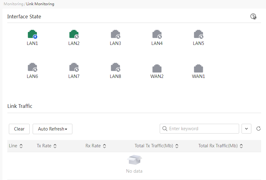
The meanings of each parameter on the page are shown in the table below.
Table 8 Parameter description
|
Item |
Description |
|
Port Status |
The current usage status of the WAN and LAN ports. Click the port icon to enter the WAN or LAN configuration page. |
|
Link |
Layer 3 interfaces on the device, such as WAN and VLAN interfaces. |
|
Tx Speed |
The message sending rate for this link. |
|
Rx Speed |
The message receiving rate for this link. |
|
Total Sent |
The total message size sent on this link. Unit is Mb. |
|
Total Received |
The total message size received on this link. Unit is Mb. |
Traffic ranking
The traffic ranking function displays terminal traffic usage, allowing viewing of terminal IP addresses, total traffic for the day, and onlink duration, facilitating administrators in analyzing and auditing user Internet behavior.
|
|
IMPORTANT: · This function will consume certain resources on the device, so please enable it with caution! · The traffic ranking list only shows the onlink IP traffic information currently accessing the Internet. · The traffic ranking list only displays traffic statistics for terminals that have connected to the device in the last 5 minutes. · The network connection count statistics refer to connections initiated by internal network IPs to the Internet. Connections initiated to the device itself and other internal network IPs, as well as connections initiated from the Internet to internal network IPs, are not counted. · The network connection count in the traffic ranking list includes TCP connection counts, UDP connection counts, and other connection counts (connections other than TCP and UDP, such as ICMP). · Total traffic refers to the overall traffic sustained by the current IP. If the IP does not engage in any Internet business for a period, it will be re-stated. · The unit conversion relationship for traffic statistics is 1 Gbit = 1,000 Mbit = 1,000,000 Kbit = 1,000,000,000 bit. |
Page Wizard: System Monitoring → Traffic Ranking
|
Select the “Enable Traffic Ranking” option to activate the user traffic ranking function. |
|
|
Configure terminal speed limits: 1. Click the speed limit icon in the operation column corresponding to the specified terminal IP address to open the terminal speed limit configuration dialog box, where you can set upload and download bandwidth as well as parameters for canceling the speed limit. 2. Click Apply. |
|
|
Configure terminal blacklisting: 1. Click the blacklisting icon in the operation column corresponding to the specified terminal IP address to open the terminal speed limit configuration dialog box, where you can set the blacklisting duration and parameters for permanent blacklisting. 2. Click Apply. |
|
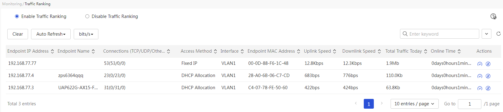
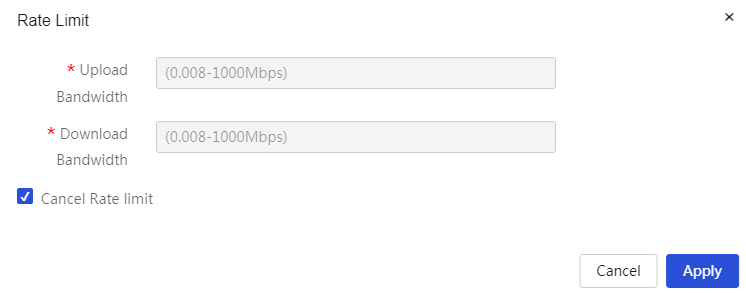
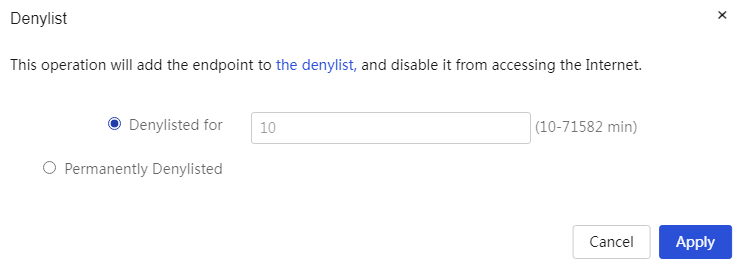
Table 9 Parameter description
|
Item |
Description |
|
Traffic ranking |
Whether to enable the traffic ranking function. If this function is enabled, the page will display the traffic information of the connected terminals. |
|
Terminal IP address |
IP address of the connected terminal |
|
Terminal name |
Username of the connected terminal |
|
Network connection count (TCP/UDP/Other) |
Number of sessions for the terminal's network connections. This mainly includes: · If the terminal transmits TCP packets, the page displays the number of TCP packet network connections. · If the terminal transmits UDP packets, the page displays the number of UDP packet network connections. · If the terminal transmits other packets, the page displays the number of other packet network connections. |
|
Access method |
Methods used for terminal access to the network, mainly divided into: · Fixed IP: The terminal accesses the network using a fixed IP address. · DHCP allocation: The terminal accesses the network using an IP address allocated by the device's DHCP. · PORTAL: An authentication method where the terminal accesses the network using Portal authentication. |
|
Ports |
Device interface used for terminal access to the network, such as VLAN1. |
|
Endpoint MAC address |
MAC address of the connected terminal |
|
Uplink Flow Rate |
Uplink traffic rate of the connected terminal |
|
Downlink Flow Rate |
Downlink traffic rate of the connected terminal |
|
Total traffic for the day |
Total transport stream (TS) traffic of the connected terminal for the day |
|
Onlink Duration |
Duration of the terminal's access to the network |
|
Task |
Operations on the terminal IP address, mainly include: · Speed limit: Apply speed limit to the terminal. ¡ Upload bandwidth: Set the upload bandwidth for the terminal. ¡ Download bandwidth: Set the download bandwidth for the terminal. ¡ Cancel speed limit: Selecting this will cancel the speed limit applied to the terminal. · Blacklist: Add the terminal to the denylist management list and prohibit its access to the Internet. ¡ Blacklist duration: Set the blacklist duration for the terminal. ¡ Permanent blacklist: Permanently blacklist the terminal. |
Network settings
Configure external network settings
About this task
In general, the external network refers to the wide area network (WAN). A wide area network is a data communications network that covers a relatively large geographical area; the Internet is a vast wide area network. By configuring the WAN interface, devices can access the external network.
Configuring the interface mode
Restriction and guidelinks
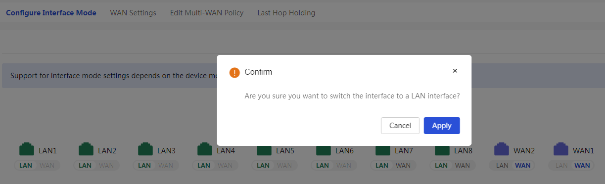
This function is used to configure the interface mode of the device's WAN/LAN ports.
· Under normal circumstances, after switching from the LAN port to the WAN port, the connection method of the WAN port to the Internet will be DHCP. The VLAN configuration information related to the interface will be lost after the interface conversion.
· Typically, the mirroring configuration of a LAN interface is cleared after the interface is changed to a WAN interface. To use the port mirroring feature after the change, configure port mirroring again.
Procedure
Page Wizard: [Network Settings/External Network Configuration/Configure Interface Mode]
|
Configure the interface mode of the device's WAN/LAN ports: 1. Click the button under the WAN/LAN interface to switchover. 2. Click Apply. |
|
Parameters
Table 10 Parameter description
|
Parameter |
Description |
|
Interface Mode |
Configure the switchover of the interface mode and set the WAN/LAN ports supported by the device. |
Configure WAN settings
About this task
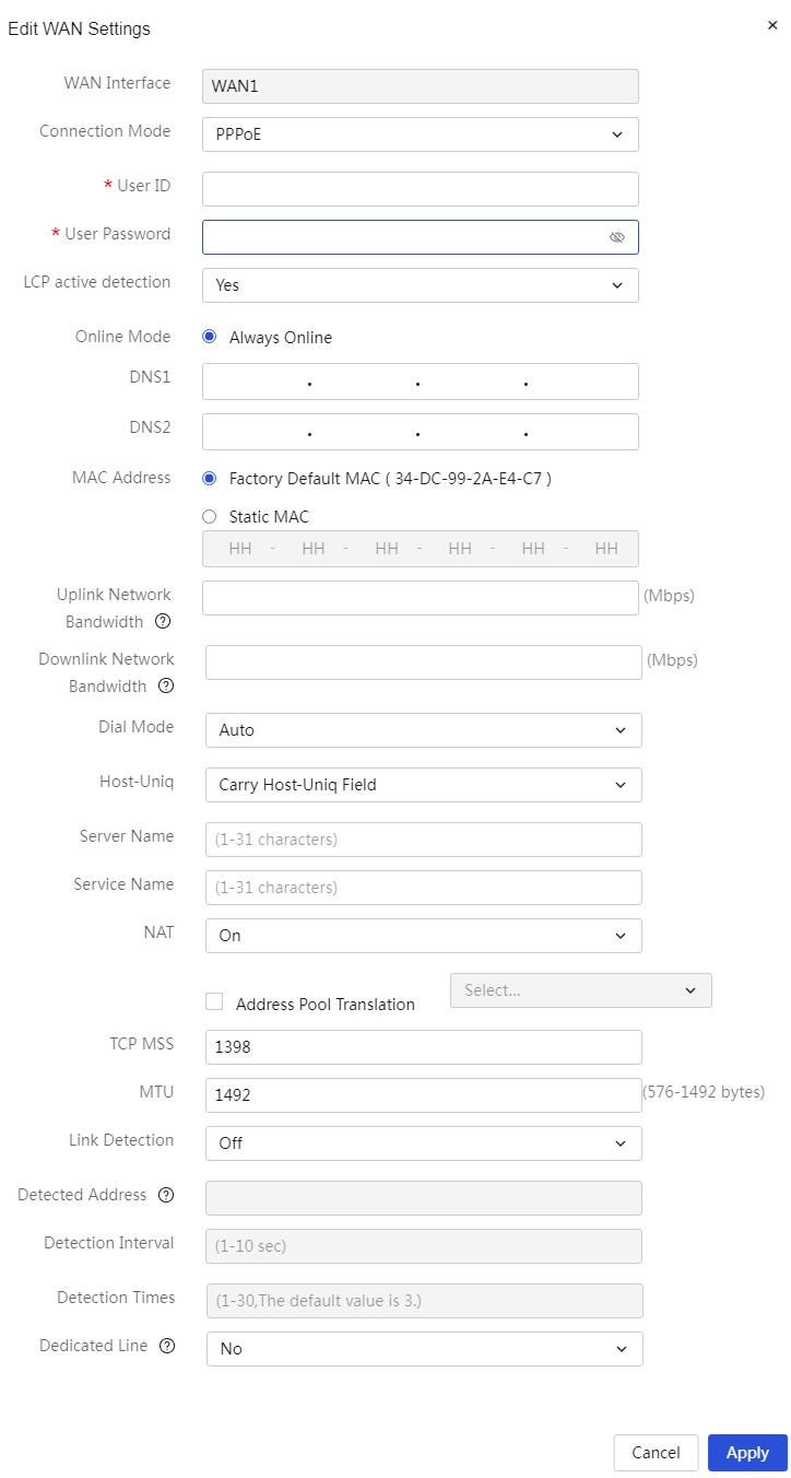
The device supports three methods for accessing the wide area network: PPPoE, DHCP, and fixed address.
Application scenarios
Table 11 Introduction to Wide Area Network Access Methods
|
Access method |
Description |
Application scenarios |
|
PPPoE |
PPPoE is a protocol that establishes a point-to-point connection over Ethernet, commonly used for authentication and dial-up connection in broadband access environments. When accessing the wide area network (WAN) using PPPoE, users need to provide specific account and password information. The router performs the dial-up connection for the user, enabling access to the Internet. |
PPPoE is suitable for home broadband access, catering to home users, small businesses, and other network environments that require dial-up connections. Users can dial up using a broadband modulation and demodulation (Modem) device (such as an ADSL Modem) to connect their home local area network (LAN) to the Internet. |
|
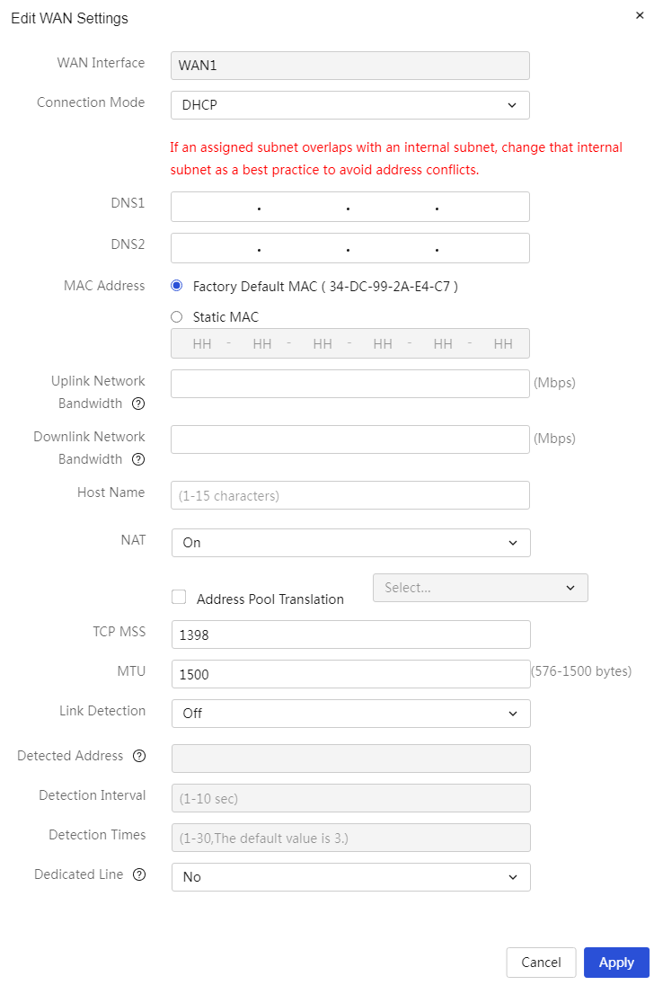
DHCP |
DHCP is a network connection method that dynamically allocates IP addresses. When a device connects to the network, it sends a request to the DHCP server, which dynamically assigns IP addresses, subnet masks, gateways, and DNS server parameters, allowing the device to quickly connect to the network and obtain the necessary IP profile. |
DHCP is suitable for large local area networks (LAN) or enterprise network environments. By automatically allocating IP addresses through the DHCP server in the network, it facilitates the management of IP address distribution for numerous devices and reduces the workload of manually configuring IP addresses. |
|
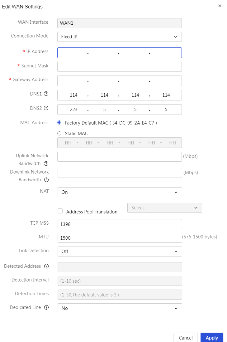
Fixed IP address |
A fixed address refers to a manually configured static IP address, including the subnet mask, gateway, and DNS server parameters. These configurations do not change based on the device's connection status. |
The fixed address method requires manually configuring a fixed IP address for network devices to ensure they always use the same IP address. This method is typically suitable for network devices that require long-term stable IP address allocation and do not need frequent changes for stable access. |
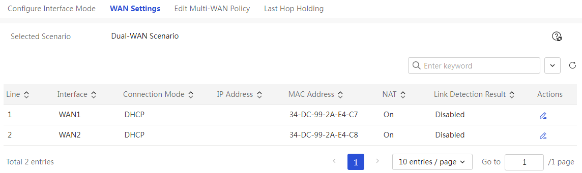
Procedure
Page Wizard: [Network Settings/External Network Configuration/WAN Configuration]
|
Item |
Description |
|
The WAN port connects to the wide area network (WAN) via PPPoE. |
|
|
The WAN port connects to the wide area network (WAN) via DHCP. |
|
|
The WAN port connects to the wide area network (WAN) via a fixed address. |
|
Parameters
Table 12 Parameter description
|
Parameter |
Description |
|
Link |
Link number for device access to the wide area network (WAN) |
|
WAN ports |
Interface for device access to the wide area network (WAN) |
|
Connection Mode |
The actual way users access the internet, options include: · PPPoE: Broadband dial-up internet access · DHCP: Automatically obtain an address from the DHCP server to access the wide area network (WAN) · Fixed Address: Access the wide area network (WAN) using a fixed address provided by the carrier |
|
Internet Account |
Username used for authentication. This parameter is provided by the carrier. This parameter can be configured when the connection mode is set to PPPoE |
|
Internet Password |
Password used for authentication. This parameter is provided by the carrier. This parameter can be configured when the connection mode is set to PPPoE |
|
LCP Active Detection |
Detecting abnormal states of the PPPoE link, options include: · Yes: Enable this function to check the link state every 20 seconds · No: Disable this function to check the link state every 2 minutes This parameter can be configured when the connection mode is set to PPPoE |
|
Onlink Mode |
The current onlink mode only supports "Always Onlink." When the connection mode is set to PPPoE, this option is enabled by default and cannot be canceled |
|
Dial-Up Method |
Dial-up method for PPPoE connection, options include: · Automatic Dial-Up: After configuration, click the <OK> button at the bottom of the dialog box to complete the dial-up automatically · Manual Dial-Up: After configuration, you need to click the <Dial> button at the bottom of the dialog box to complete the dial-up This parameter can be configured when the connection mode is set to PPPoE |
|
host-uniq |
When the internet access method is PPPoE, the current device will act as a PPPoE client to send a call message to the PPPoE server. The call message can be set to carry the host-uniq field to uniquely identify the sending PPPoE client. The PPPoE server must carry the host-uniq field in the response message, with the same content as the host-uniq field in the request message. This parameter is used to set whether the PPPoE client call message carries the host-uniq field · Carry host-uniq field: The PPPoE client call message carries the host-uniq field · Do not carry host-uniq field: The PPPoE client call message does not carry the host-uniq field This parameter can be configured when the connection mode is set to PPPoE. In some scenarios, the PPPoE server may require the PPPoE client to send a call message that carries the host-uniq field, so it is recommended to select the "Carry host-uniq field" option |
|
Server Name |
PPPoE Server Name, provided by the carrier, default is empty. This parameter can be configured when the connection mode is set to PPPoE |
|
Service Name |
Service name of the PPPoE server, provided by the carrier, default is empty. This parameter can be configured when the connection mode is set to PPPoE |
|
IP address |
Fixed IP address for device access to the wide area network (WAN), only A, B, C class IP addresses are allowed. This parameter must be configured when the connection mode is set to fixed address |
|
Subnet mask |
IP address mask or mask length, for example, 255.255.255.0. This parameter must be configured when the connection mode is set to fixed address |
|
Gateway |
Gateway address for device access to the wide area network (WAN), only A, B, C class IP addresses are allowed. This parameter must be configured when the connection mode is set to fixed address |
|
DNS1 and DNS2 |
DNS server addresses for device access to the wide area network (WAN). Preferably use DNS1 for domain name resolution; if resolution fails, use DNS2 for domain name resolution |
|
Network Upstream Bandwidth |
Actual upstream bandwidth value of the link, please consult the local carrier for confirmation |
|
Network Downstream Bandwidth |
Actual downstream bandwidth value of the link, please consult the local carrier for confirmation |
|
Host name |
The machine name that the device needs to advertise to the DHCP server. This parameter can be configured when the connection mode is set to DHCP |
|
NAT Address Translation |
Set whether multiple devices in the local area network (LAN) share the same public IP address. When "Enable" is selected, you can choose as needed: · If the device has only one public IP address, do not select "Use Address Pool Translation" · If the device has multiple public IP addresses, select "Use Address Pool Translation," and choose an already created NAT address pool. To add a new address pool, click the <Add Address Pool> button on the right to create a new address pool |
|
Link Detection Results |
Detection results of the link state for a specified IP address or domain name, mainly divided into: · Success: Indicates successful detection of the link state for the specified IP address or domain name · Failure: Indicates unsuccessful detection of the link state for the specified IP address or domain name · Not Enabled: Indicates that the link detection function is not enabled |
|
TCP MSS |
Maximum length of TCP segments for device interfaces, default is 1280 |
|
MTU |
Size of MTU (Maximum Transmission Unit) allowed through the device interface |
|
Link Detection |
Determine the link state to the specified IP address or domain name, improving link reliability. When configuring this parameter, you can choose as needed: · If you need to use ICMP packets to detect link state, select "ICMP Detection" · If you need to use DNS packets to detect link state, select "DNS Detection" · If you need to use NTP packets to detect link state, select "NTP Detection" · If you do not need to detect link state, select "Disable" |
|
Detection Address |
IP address or domain name for link detection. This parameter must be configured when link detection is set to ICMP Detection, DNS Detection, or NTP Detection |
|
Detection Interval |
Time interval for link detection. This parameter must be configured when link detection is set to ICMP Detection, DNS Detection, or NTP Detection |
|
Number of Detections |
Number of detection attempts for link detection. This parameter can be configured when link detection is set to ICMP Detection, DNS Detection, or NTP Detection |
|
Is it a Dedicated Link |
Select whether to set the current link as a dedicated link. Dedicated links typically cannot access the external network, such as medical dedicated links, police dedicated links, etc. · Yes: Set the current link as a dedicated link. After setting the dedicated link, users need to manually configure static routes · No: Do not set the current link as a dedicated link |
|
MAC |
MAC address used for device access to the wide area network (WAN) |
|
Task |
You can edit this configuration |
Editing the multi-WAN policy
About this task
You can configure settings on this page only in the multi-WAN scenario.
Application scenarios
The device supports five types of multi-WAN strategies.
Table 13 Introduction to Multi-WAN Load Sharing Strategies
|
Multi-WAN Strategy |
Description |
Application scenarios |
|
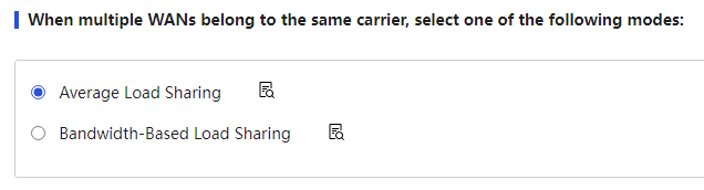
Average Load Sharing |
Each link shares the load equally |
WAN ports belong to the same carrier, and each link has the same bandwidth |
|
Bandwidth Ratio Load Sharing |
Each link shares the load according to its ratio |
WAN ports belong to the same carrier, and each link has different bandwidths |
|
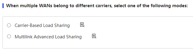
Carrier-Based Load Sharing |
Load sharing based on traffic access to the destination address |
WAN ports belong to different carriers, and each carrier provides links with the same bandwidth |
|
Advanced Multi-Link Load Sharing |
Load sharing based on traffic access to the destination address |
WAN ports belong to different carriers, and each carrier provides links with different bandwidths |
|
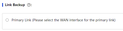
Link Backup |
One link serves as the primary link, while others serve as backup links to maintain network stability |
If network stability is a high priority, you can set up backup links. |
Procedure
Page Wizard: [Network Settings/External Network Configuration/Modify Multi-WAN Strategy]
|
1. Set up multi-WAN access mode with the same carrier: 2. Select "Average Load Sharing" or "Bandwidth Ratio Load Sharing" mode 3. Click <Apply> button to complete the configuration |
|
|
1. Set up multi-WAN access mode with different carriers: 2. Select "Carrier-Based Load Sharing" or "Multi-Link Advanced Load Sharing" mode 3. Click <Apply> button to complete the configuration |
|
|
1. Set up link backup: 2. Select the primary link and backup link 3. Click <Apply> button to complete the configuration |
|
Parameters
Table 14 Parameter description
|
Item |
Description |
|
Multiple WANs belong to the same carrier |
When a device has multiple WAN ports connected to the same carrier link, you can select the load sharing mode as needed: · If the bandwidth of each link is consistent, it is recommended to select "Average Load Sharing." · If the bandwidth of each link is inconsistent, it is recommended to select "Bandwidth Ratio Load Sharing" and set the allocation bandwidth ratio for the links. After setting, you need to click the "Apply" button to make the configuration take effect. |
|
Multiple WANs belong to different carriers |
When a device has multiple WAN ports connected to different carrier links, you can select the load sharing mode as needed: · If the bandwidth of the links provided by each carrier is consistent, it is recommended to select "Carrier-Based Load Sharing" and choose the corresponding carrier for each WAN port and the default link. · If the bandwidth of the links provided by each carrier is inconsistent, it is recommended to select "Advanced Multi-Link Load Sharing," set the allocation bandwidth ratio for the links, and choose the corresponding carrier for each WAN port and the default link. After setting, you need to click the "Apply" button to make the configuration take effect. |
|
Link Backup |
When accessing multiple WANs, one link is the primary link, while the others are backup links to maintain network stability. When configuring this parameter, first select "Primary Link (please choose the WAN interface as the primary link)" and the corresponding "Link n," then select the backup link "Link m." Note that n and m cannot be the same; otherwise, link backup cannot be achieved. If the selected primary link has the link probing function enabled (configured in the external network settings - WAN configuration), the system will change the actual effective primary link based on the probing results. If the selected primary link does not have the link probing function enabled, the system will change the actual effective primary link based on the physical status of the interface. |
|
Allocation Bandwidth Ratio of Links |
Set the default bandwidth ratio for each link. When setting this parameter, ensure that at least one link has a bandwidth ratio that is not 0. When the multi-WAN strategy is set to "Bandwidth Ratio Load Sharing" or "Advanced Multi-Link Load Sharing," this parameter needs to be set. Note: The input range for this parameter is integers from 0 to 100. |
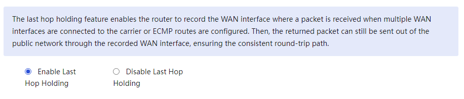
Configure last hop holding
Procedure
Page Wizard: [Network Settings/External Network Configuration/Save Interface Next Hop]
|
Set the WAN port to save the function of the previous hop on the interface |
|
Parameters
Table 15 Parameter description
|
Parameter |
Description |
|
Enable the Save Previous Hop Function |
Whether to enable the Save Previous Hop Function. If this function is enabled, in multi-WAN scenarios, messages entering and leaving the local area network (LAN) will be forwarded through the same WAN interface. |
Configuring LAN settings
Introduction
Use this feature to assign LAN interfaces of the device to VLANs, configure VLAN interface parameters, enable Dynamic Host Configuration Protocol (DHCP), and configure DHCP parameters.
DHCP (Dynamic Host Configuration Protocol) is a LAN protocol mainly used to assign IP addresses to hosts within the LAN. DHCP supports both dynamic and static address assignment mechanisms:
· The dynamic address assignment function is configured on the interface, allowing the user host to dynamically obtain an IP address. When the time expires or the host explicitly relinquishes the address, it can be used by other hosts. This assignment method is suitable for LAN environments where hosts acquire IP addresses with a certain validity period.
· The statically assigned IP address is not bound to the client's interface; it only needs to be bound to the host's NIC MAC address, providing a right-to-use (RTU) that is permanent. This assignment method is suitable for LAN environments where hosts acquire IP addresses with an infinite lease period.
VLAN
About this task
Assign the LAN interfaces on the device to the specified VLAN, so that hosts in the same VLAN can communicate and hosts in different VLANs cannot directly communicate.
Restriction and guidelinks
1. When you configure a VLAN as the PVID for an interface on the detailed port settings page, make sure the VLAN has been created.
2. Plan the VLANs to which each LAN interface belongs on the device, and create the corresponding VLAN interface on the LAN settings page.
3. The PVID identifies the default VLAN of a port. Untagged packets received on a port are considered as the packets from the port PVID.
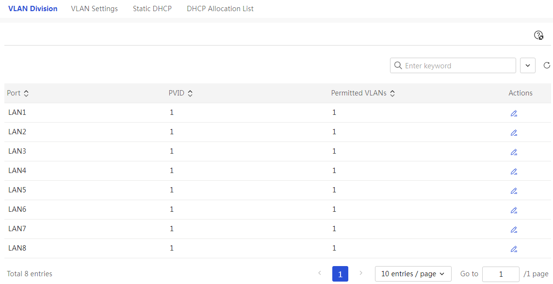
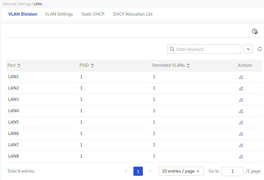
Procedure
Page Wizard: [Network Settings/LAN Configuration/VLAN Partitioning]
|
This page provides you with the following main functions: · Display information about the VLANs allowed through the port · Set the VLANs allowed through the port |
|
|
Set the VLANs allowed through the port |
|

Parameters
Table 16 Parameter description
|
Item |
Description |
|
Port name |
LAN interface that needs VLAN segmentation |
|
PVID |
Default VLAN for this port |
|
Permitted VLANs |
All VLANs allowed through this LAN port |
|
VLANs to be selected |
All VLANs that have been created on the device. When configuring this parameter, select the VLAN numbers below the "VLANs to be selected" check box, or directly check the "VLANs to be selected" check box to select all VLANs, then click the right orientation button below "VLANs to be selected" to add the port to the selected VLANs |
|
Selected VLANs |
The VLANs to which this port has been assigned. When configuring this parameter, select the VLAN numbers below the "Selected VLANs" check box, or directly check the "Selected VLANs" check box to select all VLANs, then click the left orientation button below "Selected VLANs" to remove the port from the joined VLANs |
|
Task |
This configuration can be edited |
Configure VLAN settings
About this task
Create a VLAN interface for the device to connect to the intranet, and use the VLAN interface as the gateway for the intranet device to provide DHCP service.
Restriction and guidelinks
If you enable DHCP service for a VLAN interface and then disable it, the system will delete the static DHCP bindings of this VLAN interface on the Static DHCP page at the same time.
Procedure
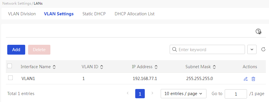
Page Wizard: [Network Settings/LAN Configuration/VLAN Configuration]
|
This page provides you with the following main functions: · Display detailed information of the added VLANs · Adding a VLAN · Delete the added VLANs · Modify the added VLANs |
|
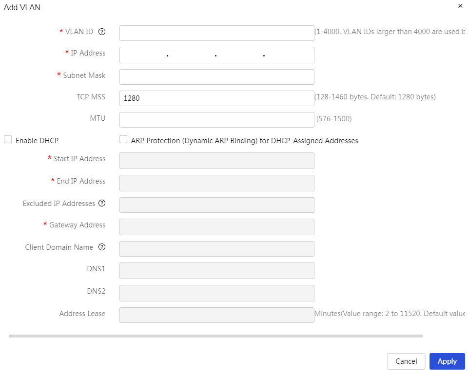
|
Add VLAN: 1. Click<the add>button to open the VLAN dialog box, and set parameters such as VLAN ID, IP address, subnet mask, etc. 2. Click<the confirm>button to complete the configuration |
|
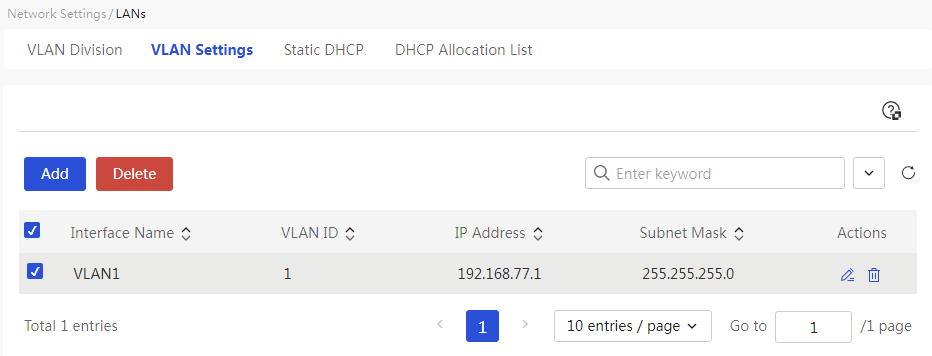
|
Delete added VLANs: 1. Select the radio box in front of the VLAN you want to delete 2. Click<the delete>button to open the confirmation dialog box, then click<the confirm>button to complete the configuration |
|
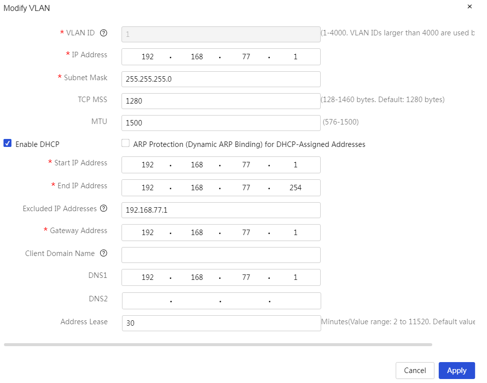
|
Modify added VLANs: 1. Click the edit icon in the action column corresponding to the VLAN you want to modify, open the modify VLAN dialog box, and change the relevant configuration items 2. Click Apply. |
|
Parameters
Table 17 Parameter description
|
Item |
Description |
|
Port name |
The name of this VLAN interface |
|
VLAN ID |
The ID number of this VLAN interface |
|
Connection mode |
The method for the device to obtain an IP address, options include: · DHCP: The device obtains an IP address from the DHCP server. When selecting this option, a DHCP server must exist in the network environment. · Static address: Manually create the IP address, subnet mask, and other information for the VLAN interface. |
|
IP address of the interface. |
The IP address of this VLAN interface |
|
Subnet mask |
The mask or mask length of this IP address, for example 255.255.255.0 |
|
TCP MSS |
The maximum segment length value for TCP packets on this VLAN interface, default is 1280 |
|
MTU |
The size of the MTU value allowed for this VLAN interface |
|
Enabling the DHCP service |
Whether to enable the DHCP service function. If this function is enabled, the device will dynamically assign IP addresses to clients connected to the device (such as computers connected to the device). The DHCP service function is disabled by default. |
|
ARP protection for DHCP allocated addresses (dynamic binding) |
Whether to enable ARP protection for DHCP allocated addresses (dynamic binding). If this function is enabled, the device will bind the client's MAC address to dynamically allocated IP addresses. ARP protection for DHCP allocated addresses (dynamic binding) is disabled by default. |
|
Starting address of the address pool |
The starting IP address of the DHCP server's address pool |
|
Ending address of the address pool |
The ending IP address of the DHCP server's address pool; the ending address cannot be less than the starting address. |
|
Excluded addresses |
IP addresses that the device cannot assign to clients. For example: gateway address |
|
Gateway |
The gateway address corresponding to the address pool. If the gateway address is not configured, it may cause network connectivity issues. |
|
Client domain name |
The domain name suffix assigned by the device to the client. Allowed characters for the client domain name include letters [a-z, A-Z], digits, and symbols - and ., and cannot start or end with the symbol .. · When containing the symbol ., the length of characters before and after the symbol cannot exceed 63 characters. If multiple symbols . exist, they cannot be entered consecutively, for example .. · When not including the symbol ., the value can be between 1-63 characters. |
|
DNS1 and DNS2 |
The DNS server addresses carried by the DHCP server when assigning IP addresses. DNS1 is used first for domain name resolution. If resolution fails, DNS2 will be used for domain name resolution. |
|
Address lease |
The lease period for the IP address assigned by the DHCP server to the client. When the lease period expires, the DHCP server will reclaim the IP address, and the client must reapply to the router (the client generally will apply automatically). |
|
Task |
This configuration can be edited and deleted. |
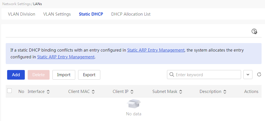
Configure static DHCP
About this task
To assign fixed IP addresses to some clients, configure static DHCP to bind client MAC addresses to IP addresses.
Restriction and guidelinks
1. Make sure statically bound client IP addresses are not contained in the WAN interface IP address range specified on the device.
2. When configuring static DHCP, if the client IP address set is already occupied by another terminal, the terminal corresponding to the client MAC will be assigned a different IP address when it comes onlink. Once the previously set client IP address is released, the terminal corresponding to the client MAC will be reassigned the designated IP address.
3. Before configuring static DHCP, first enable the DHCP service on the target VLAN interface.
Procedure
Page Wizard: [Network Settings/LAN Configuration/Static DHCP]
|
This page provides you with the following main functions: · Display detailed information of added DHCP static binding relationships · Add DHCP static binding relationships · Delete DHCP static binding relationships · Modify added DHCP static binding relationships · Import static DHCP address table |
|
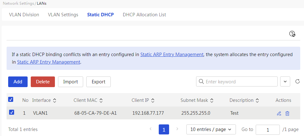
|
Add DHCP static binding relationships: 1. Click the <Add> button to open the new DHCP static binding relationship dialog box, and set parameters such as interface, client MAC address, and client IP. 2. Click the <OK> button to complete the configuration. |
|
|
Delete added DHCP static binding relationships: 1. Select the radio box in front of the DHCP static binding relationships you want to delete. 2. Click the <Delete> button to open the confirmation dialog box, then click the <OK> button to complete the configuration. |
|
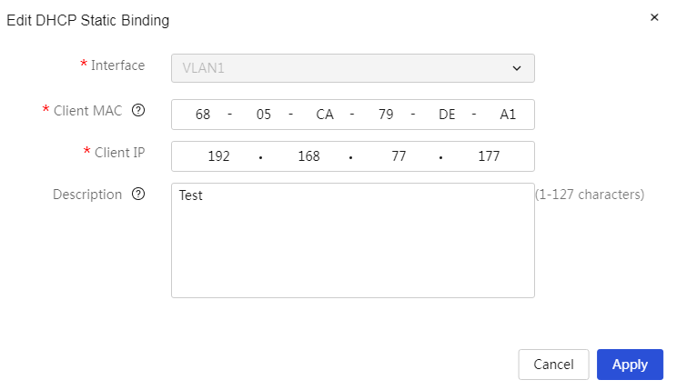
|
Modify added DHCP static binding relationships: 1. Click the edit icon in the operation column corresponding to the DHCP static binding relationship you want to modify, which opens the DHCP static binding relationship dialog box to modify the relevant configuration items. 2. Click Apply. |
|
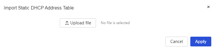
|
Import static DHCP address table: 1. Click the import icon on the interface to open the import static DHCP address table dialog box. Click the <Upload File> button to select the static DHCP address table to import. 2. Click the <OK> button to complete the configuration. |
|

Parameters
Table 18 Parameter description
|
Item |
Description |
|
No. |
Static DHCP policy number |
|
Ports |
The VLAN interface created on the device. This policy binds the IP address and MAC address obtained from a specific interface. |
|
Client MAC |
The MAC address of the client. Addresses consisting entirely of 0s or Fs are not supported here. |
|
Client IP Addresses |
The IP address assigned to the client. |
|
Subnet mask |
The mask or mask length for this IP address. For example, 255.255.255.0. |
|
Description |
A description of the policy, allowing for a simple explanation for easier use. |
|
Task |
This configuration can be edited and deleted. |
DHCP allocation list
Procedure
Page Wizard: [Network Settings/LAN Configuration/DHCP Allocation List]
|
This page provides you with the following main functions: · Display detailed information allocated by the device's DHCP · One-click reclaim IP address · Static allocation of IP address |
|
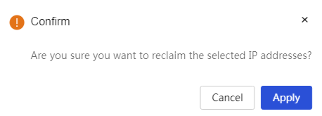
|
One-click reclaim IP address: 1. Select the IP address you want to reclaim from the list 2. Click the <One-click reclaim> button, a confirmation prompt dialog box will pop up. Click the <Confirm> button to complete the configuration |
|
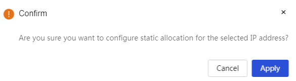
|
Static allocation of IP address: 1. Select the IP address you want to statically allocate from the list 2. Click the <Static allocation> button, a confirmation prompt dialog box will pop up. Click the <Confirm> button to complete the configuration |
|
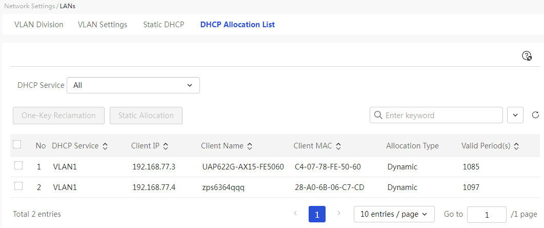
Parameters
Table 19 Parameter description
|
Parameter |
Description |
|
Number |
Number of DHCP Allocation Information |
|
DHCP |
VLAN Interface with DHCP Service Enabled on the Device |
|
Client IP Addresses |
Client's IP Address |
|
Client Name |
Client's Host Name |
|
Client MAC |
MAC address of the client. |
|
Validity Time |
Lease Duration of the IP Address Assigned by the DHCP Server to the Client. Once the lease expires, the DHCP server will reclaim the IP address, and the client must reapply to the router (the client usually requests automatically). |
|
One-Click Reclaim |
Reclaim the IP Address Assigned by the DHCP Server. To configure this parameter, select the IP addresses to be reclaimed from the list, click the <One-Click Reclaim> button, and in the confirmation prompt that appears, click the <Acknowledge> button to confirm the reclamation of the selected IP addresses. |
|
Static allocation |
Statically Bind the IP Address Dynamically Assigned by the DHCP Server. To configure this parameter, select the client IP to be statically bound from the list, click the <Static Allocation> button, and in the confirmation prompt that appears, click the <Acknowledge> button to confirm setting the DHCP dynamically assigned IP address to static allocation. |
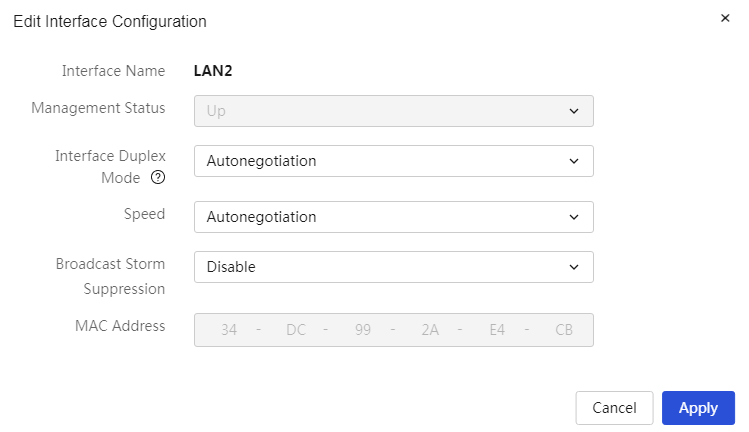
Manage ports
About this task
Use the port management function to view the interface type, interface duplex mode, speed, MAC address, and broadcast storm suppression information of each physical interface on the device, set the management status of the WAN interfaces, and edit interface configuration.
Procedure
Page Wizard: [Network Settings/Port Management]
|
This page provides you with the following main functions: · Display detailed information about device ports. · Editing port settings |
|
|
Modify port configuration: 1. Click the edit icon in the operation column corresponding to the port you want to modify, which will open the modify port dialog box to adjust the related configuration items. 2. Click Apply. |
|

Parameters
Table 20 Parameter description
|
Item |
Description |
|
Physical port |
Physical ports of the device, such as WAN1, LAN1 |
|
Port name |
Physical port names of the device |
|
Port type |
Port types of the device, mainly divided into: · WAN: Interface for accessing the wide area network · LAN: Interface for accessing the local area network |
|
Port mode |
Operating modes of the port, mainly divided into: · Autonegotiation: Duplex and rate states are determined by autonegotiation between this port and the peer port · Full duplex: The port can receive and transmit packets simultaneously · Half duplex: The port can either send or receive packets at the same time |
|
Transmission baud rate |
Port rates, including autonegotiation, 10Mbps, 100Mbps, 1Gbps, 2.5Gbps (supported by some device ports) |
|
MAC |
MAC address of the port |
|
Broadcast storm suppression |
Function to suppress the propagation of a large number of broadcast packets within the local area network, which can prevent network congestion and ensure the normal operation of network services. The suppression level can be selected as needed: "No suppression," "Low," "Medium," "High" |
|
Admin Status |
Operating states of the port, mainly divided into: · Enabled: The device enables this port · Disabled: The device disables this port When the port type is LAN, this parameter cannot be modified and defaults to enabled state |
Configure NAT
Introduction
Network Address Translation (NAT) translates an IP in the IP packet header to another IP address. It enables private hosts to access external networks and external hosts to access private network resources.
NAT supports the following address translation methods:
· Port mapping—Allows multiple internal servers (for example, Web, mail, and FTP servers) to provide services for external hosts by using one public IP address and different port numbers. This method saves public IP address resources.
· One-to-one mapping—Creates a fixed mapping between a private address and a public address. Use this method for fixed network access requirements. This method is preferred if you need to use a fixed public IP address to access an internal server.
NAT provides the following advanced features:
· NAT hairpin—Allows internal users to access internal servers through NAT addresses. This feature is applicable if you want the gateway to control the internal user traffic destined for the internal server that provides services for external users through a public IP address.
· NAT ALG—If an application layer service (for example, FTP or RTSP) exists between the internal and external networks, enable NAT ALG for the application layer protocol. It ensures that the data connection of this protocol can be correctly established after address translation.
Configure a virtual server
Procedure
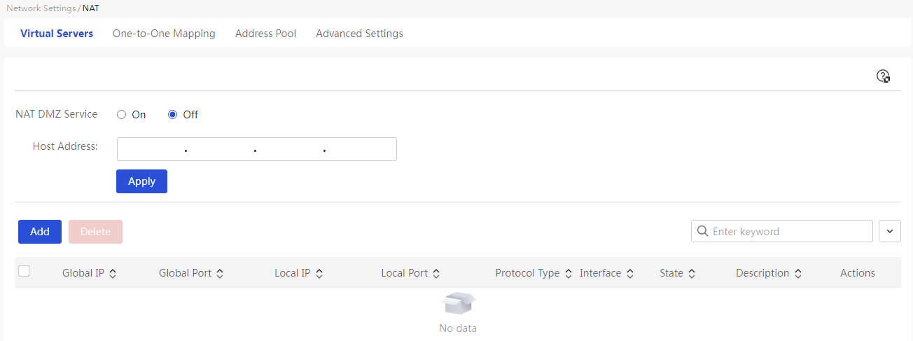
Page Wizard: [Network Settings/NAT Configuration/Virtual Server]
|
This page provides you with the following main functions: · Display detailed information of added virtual servers · Enable NAT DMZ server · Adding a NAT port mapping · Delete added NAT port mappings · Modify added NAT port mappings |
|
|
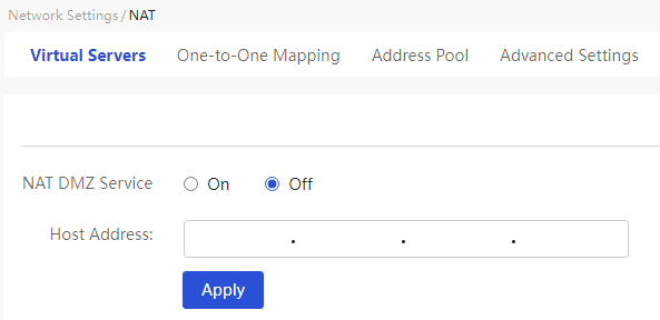
Enable NAT DMZ server: 1. Select the "Enable" option and set the host address parameter 2. Click<Apply> button to complete the configuration |
|
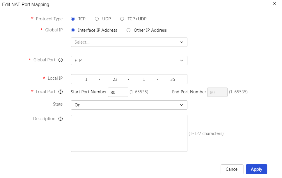
|
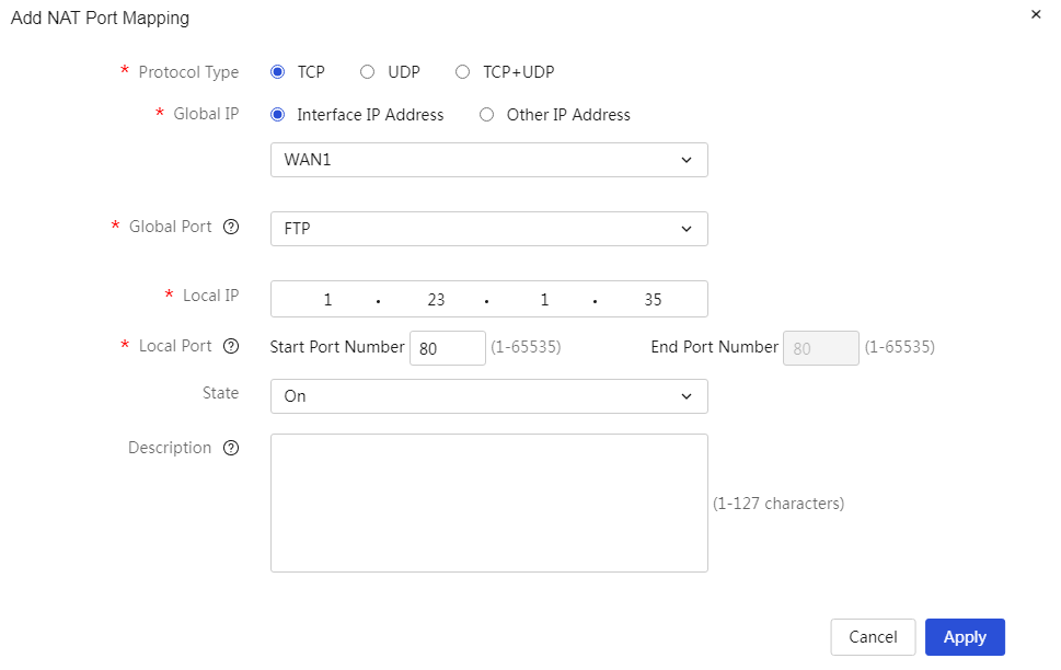
Add NAT port mapping: 1. Click<Add> button to open the Add NAT Port Mapping dialog box, and set parameters such as protocol type, external address, external port, etc. 2. Click<OK> button to complete the configuration |
|
|
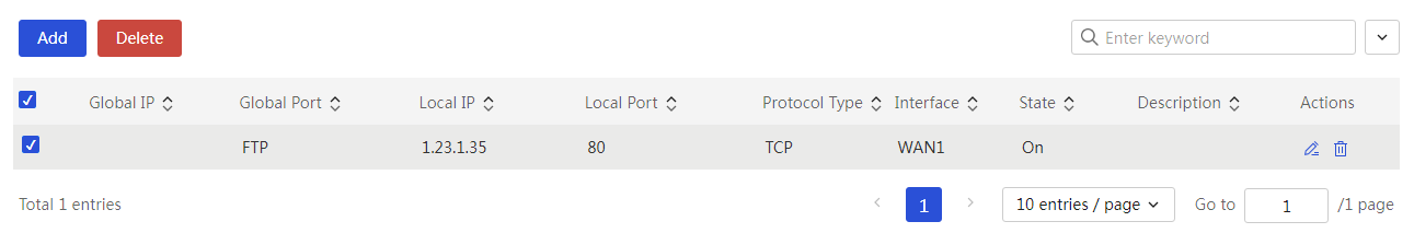
Delete added NAT port mapping: 1. Select the radio box in front of the NAT port mapping you want to delete 2. Click<Delete> button to open the confirmation prompt dialog box, then click<OK> button to complete the configuration |
|
|
Modify added NAT port mapping: 1. Click the edit icon in the operation column corresponding to the NAT port mapping you want to modify, open the Modify NAT Port dialog box, and modify the relevant configuration items 2. Click Apply. |
|
Parameters
Table 21 Parameter description
|
Parameter |
Description |
|
NAT DMZ Service |
The virtual server function can enhance the security of the local area network (LAN). When configuring this parameter, you can select as needed: · If this function is enabled, when the device receives a request from the external network, it first checks the virtual service list. If there is a match, it forwards the request to the corresponding IP address; if no match is found, it forwards the request to the DMZ host. · If the NAT DMZ service is disabled: when an external request does not match the virtual service list, the request message is discarded directly. |
|
Host Address |
IP address of the DMZ host |
|
Protocol |
Transmission protocol used by the internal host. When configuring this parameter, you can select as needed: · If the internal host uses the TCP transmission protocol, select “TCP”. · If the internal host uses the UDP transmission protocol, select “UDP”. · If the internal host uses both TCP and UDP transmission protocols, select “TCP+UDP”. |
|
External Address |
The public network address on the device can be set in two ways: · Current interface IP address: the IP address of the device's WAN port. · Other addresses: other public IP addresses on the device. |
|
Ports |
You can directly use the WAN interface IP address as the external address when selecting the interface. |
|
External port |
Mapping the internal host to the external address, the open ports on the external address can be configured as needed: · If the service provided to the outside is FTP, select “FTP”. · If the service provided to the outside is TELNET, select “TELNET”. · If the service provided to the outside is other, enter the range of port numbers used by the service. When configuring this parameter, the starting port number cannot be greater than the ending port number. |
|
Internal Address |
IP address of the internal host, which needs to provide specified services to the outside. |
|
Internal port |
The actual open service ports on the internal host. |
|
Enabling state. |
The execution actions of this policy are mainly divided into: · Enabled: indicates that this policy is enabled and takes effect immediately after configuration. · Not enabled: indicates that this policy is not currently enabled. |
|
Description |
Description information for the policy can provide a brief description, making it easier to use. |
|
Task |
You can edit and delete this configuration. |
Configure one-to-one mappings
About this task
If a one-to-one mapping of an internal IP address to a public IP address is needed, this function can be set.
Restriction and guidelinks
If the device has only one public address, do not configure a one-to-one mapping by using the public address.
Procedure
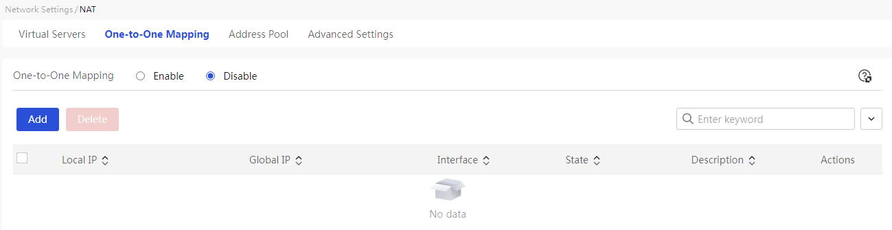
Page Wizard: [Network Settings/NAT Configuration/One to One Mapping]
|
This page provides you with the following main functions: · Display details of added one to one mappings · Enable one to one mapping · Add NAT one to one mapping · Delete added NAT one to one mappings · Modify added NAT one to one mappings |
|
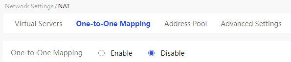
|
Select the "Enable" option to activate the one to one mapping function |
|
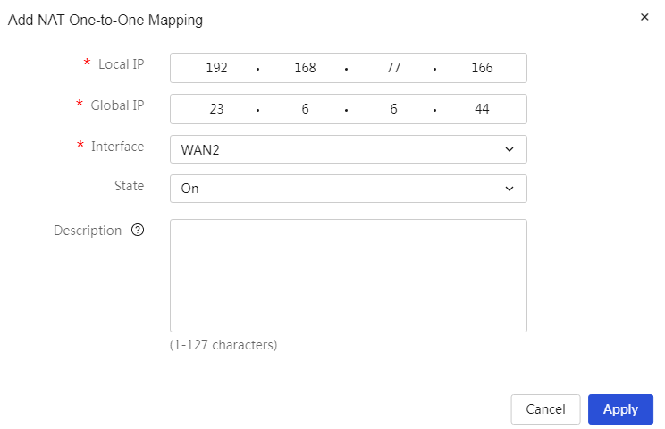
|
Add NAT one to one mapping: 1. Click<Add> button to open the add NAT one to one mapping dialog box, and set the internal address, external address, interface, and other parameter information 2. Click<OK> button to complete the configuration |
|
|
Delete added NAT one to one mapping: 1. Select the radio box in front of the NAT one to one mapping you want to delete 2. Click<Delete> button to open the confirmation prompt dialog box, then click<OK> button to complete the configuration |
|
|
Modify added NAT one to one mapping: 1. Click the edit icon in the operation column corresponding to the NAT one to one mapping you want to modify to open the modify application dialog box, and change the relevant configuration items 2. Click Apply. |
|
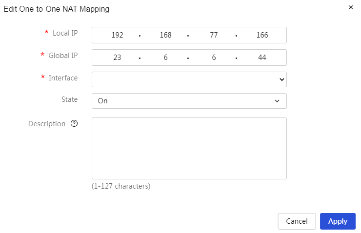
Parameters
Table 22 Parameter description
|
Parameter |
Description |
|
Internal Address |
IP address of the internal network host. This host needs to provide specified services externally. |
|
External Address |
Public IP address of the device. |
|
Ports |
The WAN port of the device mapped by the internal network host for external access. The packets are mapped through this interface. If this parameter is not set, it will apply to all WAN ports. |
|
Status |
The execution actions of this policy are mainly divided into: · Enabled: Indicates that this policy is enabled, and it takes effect immediately after configuration. · Not Enabled: Indicates that this policy is not currently enabled. |
|
Description |
Description information of the policy, allowing for a simple description of the policy for convenience. |
Configure address pools
Procedure
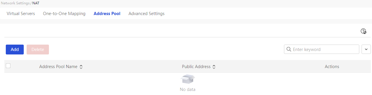
Page Wizard: [Network Settings/NAT Configuration/Address Pool]
|
This page provides you with the following main functions: · Display detailed information of the added address pool · Add NAT address pool · Delete added NAT address pool · Modify added NAT address pool |
|
|
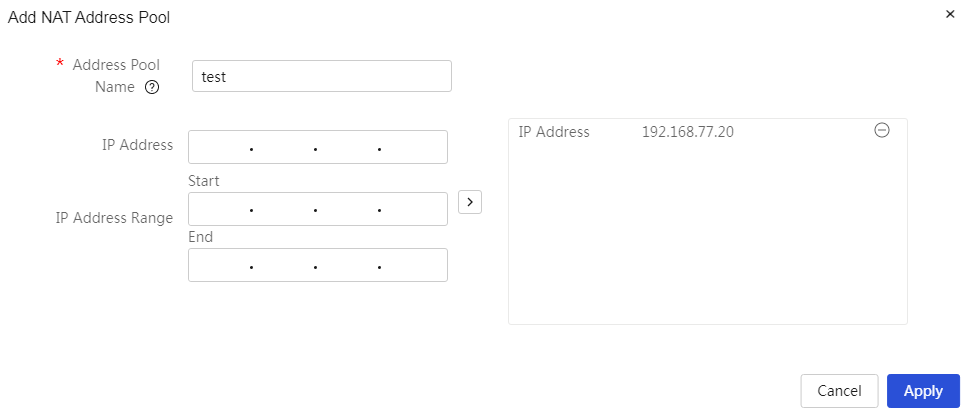
Add NAT address pool: 1. Click<Add> button to open the Add NAT Address Pool dialog box, and set the address pool name, IP address, and other parameter information 2. Click<OK> button to complete the configuration |
|
|
Delete added NAT address pool: 1. Select the radio box in front of the NAT address pool you want to delete 2. Click<Delete> button to open the confirmation prompt dialog box, then click<OK> button to complete the configuration |
|
|
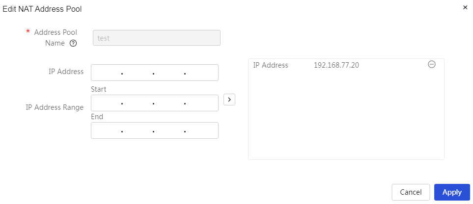
Modify added NAT address pool: 1. Click the edit icon in the operation column corresponding to the NAT address pool you want to modify, open the Modify Application dialog box, and change the relevant configuration items 2. Click Apply. |
|
Parameters
Table 23 Parameter description
|
Parameter |
Description |
|
Address Pool Name |
The name of the public IP address pool used for NAT conversion, which can consist of Chinese characters, digits, letters, and underscores. |
|
IP address |
The public IP address provided by the carrier. When configuring this parameter, after entering the IP address, you need to click the “>” button on the right side of the configuration item (CI) to submit the address pool content. |
|
IP Range |
Public IP address range. If the carrier provides multiple public IP addresses, this item must be configured. When configuring this parameter, after entering the starting and ending IP addresses, you need to click the “>” button on the right side of the configuration item (CI) to submit the address pool content. The number of IP addresses within a single IP address range cannot exceed 256, and unreasonable IP addresses cannot exist. |
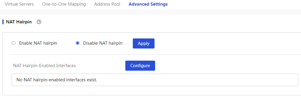
Configure NAT Hairpin
About this task
If internal users need to access internal servers using public IP addresses like external users, the NAT hairpin function can be enabled.
Before you configure NAT hairpin, perform more than one of the following tasks:
· Configure a mapping between the internal server IP address and port and the public IP address and port on the virtual server configuration page.
· Configure a mapping between the private user IP address and public IP address on the one-to-one mapping configuration page.
Procedure
Page Wizard: [Network Settings/NAT Configuration/Advanced Configuration]
|
Set up NAT hairpinning: 1. Enable the NAT hairpinning function and set the current NAT hairpinning effective interface. 2. Click the <Apply> button to complete the configuration. |
|
Parameters
Table 24 Parameter description
|
Parameter |
Description |
|
NAT hairpin |
Select whether to enable the NAT hairpin · Select the “Available Interfaces” · Select one or more interfaces from the available interfaces list, and click the “>” button below the “Available Interfaces” · If you want to cancel a selected interface, check this interface in the selected interfaces list, and click the “<” button below the “Available Interfaces” Once the settings are complete, click the <OK> button to apply the configuration. |
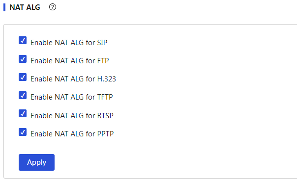
Configure NAT ALG
Procedure
Page Wizard: [Network Settings/NAT Configuration/Advanced Configuration]
|
Set NAT ALG: 1. Enable the NAT ALG function for the specified protocol. 2. Click<Apply>button to complete the configuration. |
|
Parameters
Table 25 Parameter description
|
Parameter |
Description |
|
NAT ALG |
To ensure that the data connections of certain application layer protocols can be correctly established after port mapping or one to one mapping, you need to enable the NAT ALG function for the specified protocol. When configuring this parameter, you can select as needed: · If the message uses the SIP protocol, select "Enable SIP." · If the message uses the FTP protocol, select "Enable FTP." · If the message uses the H323 protocol, select "Enable H323." · If the message uses the TFTP protocol, select "Enable TFTP." · If the message uses the RTSP protocol, select "Enable RTSP." · If the message uses the PPTP protocol, select "Enable PPTP." After the settings are complete, you need to click the "Apply" button to make the configuration take effect. |
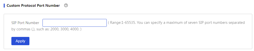
Configure user-defined protocol port numbers
Procedure
Page Wizard: [Network Settings/NAT Configuration/Advanced Configuration]
|
Set the custom protocol port number: 1. Set the custom SIP port number 2. Click<Apply>button to complete the configuration. |
|
Parameters
Table 26 Parameter description
|
Parameter |
Description |
|
Custom Protocol Port Number |
When setting up a SIP server, if the SIP protocol port number used is not 5060, you need to customize the SIP protocol port number. The input range for the SIP port number is 1-65535, and you can enter up to 7 port numbers, separated by commas, such as: 2000,3000,4000. |
Configure network connections
Procedure
Page Wizard: [Network Settings/NAT Configuration/Advanced Configuration]
|
Set up network connection: 1. Configure parameters such as the current number of network connections, total number of network connections, and select the interface to clear network connections. 2. Click the <Apply> button to complete the setup. |
|

Parameters
Table 27 Parameter description
|
Parameter |
Description |
|
Network Connections |
Current Number of Network Connections: The total number of network connections established by the current device Total Network Connections: The total number of network connections that the device can create, which is the total number of sessions. When the set value is less than the current number of established network connections, it will affect the establishment of new connections. Select the interface to clear network connections: The interface from which network connections need to be cleared. If there is a network attack affecting business operations or changes to firewall rules, policy-based routing (PBR), NAT configurations, etc., that have not taken effect immediately, you can try to clear the network connections. When configuring this parameter, please exercise caution as clearing network connections may impact the normal operation of existing services. |
Power the AP over PoE
About this task
PoE (Power over Ethernet) refers to the provision of power to an external powered device (PD) via copper ports using twisted pair cables.
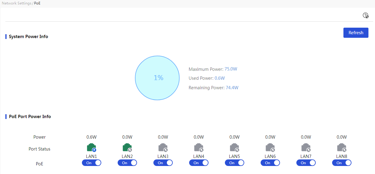
Configure PoE power supply
Procedure
Page Wizard: [Network Settings/POE Power Supply]
|
Activate the power supply function of the device's PoE port |
|
Parameters
Table 28 Parameter description
|
Parameter |
Description |
|
Overall system PoE power supply usage rate |
Percentage of the current used power supply compared to the overall system's maximum power supply |
|
Max Power |
Overall system maximum power supply |
|
Current power usage |
Current power supply used by the overall system |
|
Current remaining power |
Current unused power supply of the overall system |
|
Current Power |
Current power supply used by PoE ports |
|
Port Status |
Power supply status of PoE ports, including: · Port Down-PoE power supply: On · Port Down-PoE power supply: Off · Port Up-PoE power supply: On · Port Up-PoE power supply: On (Power supply abnormal: total power overload/port power overload). · Port Up-PoE power supply: Off |
|
PoE Switch |
Turn on or off the power supply function of PoE ports |
IPv6 configuration
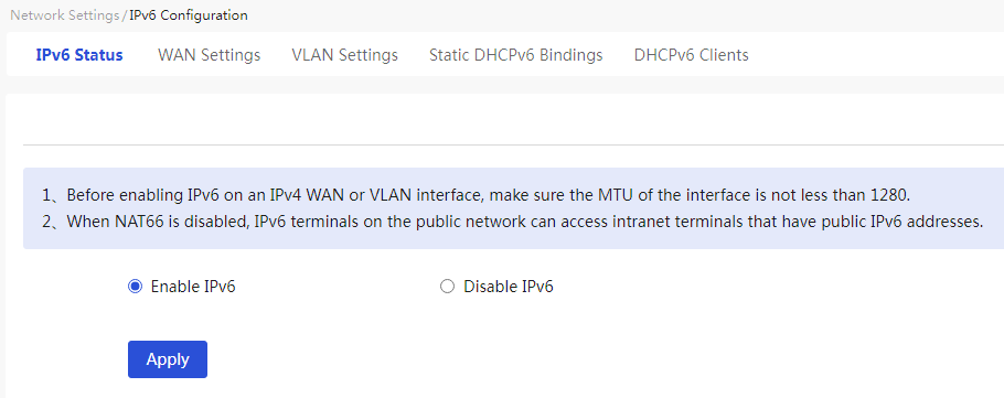
Introduction
Use this function to enable IPv6 for the device, configure WAN and VLAN interfaces, and configure static DHCPv6 bindings.
IPv6 (Internet Protocol Version 6) is the second-generation standard protocol of the network layer, also known as IPng (IP Next Generation). It is a set of specifications designed by the Internet Engineering Task Force (IETF) and is an upgrade of IPv4.
Power switch
Procedure
Page Wizard: [Network Settings/IPv6 Configuration/Switch]
|
Enable the device's IPv6 function |
|
Parameters
Table 29 Parameter description
|
Item |
Description |
|
Power switch |
Whether to enable the IPv6 For the configuration to take effect, click Apply. |
Configure WAN settings
Restriction and guidelinks
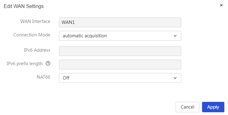
1. When the WAN interface connection mode is set to automatically obtain, the DHCPv6 message will carry IANA and IAPD, and IAPD will not carry IA Prefix. Whether an IPv6 prefix and its length can be obtained will be determined by the server algorithm.
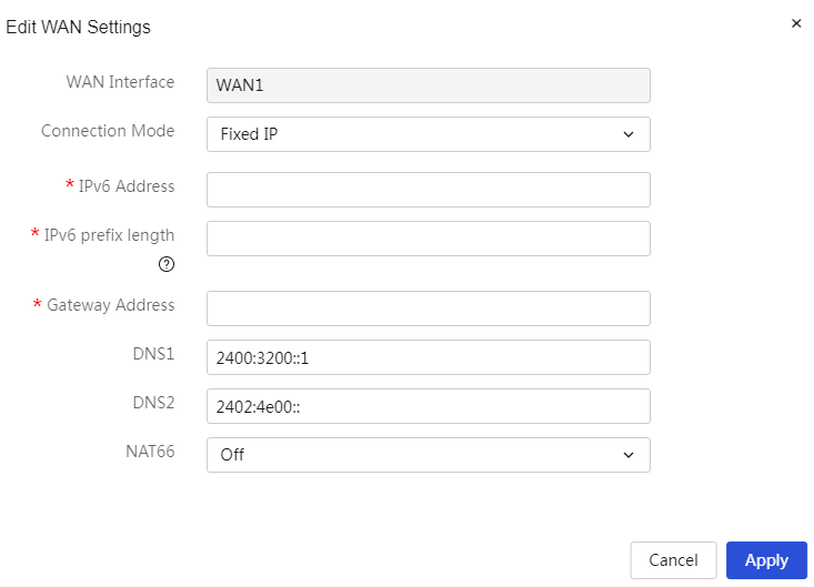
2. When the WAN interface connection mode is set to a fixed address, if the input range of the IPv6 prefix length is 48-64, that address will be used as the prefix.
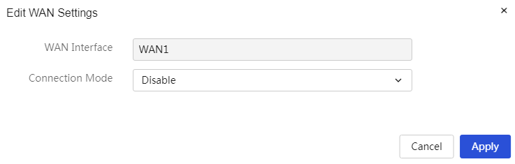
Procedure
Page Wizard: [Network Settings/IPv6 Configuration/WAN Configuration]
|
The WAN port does not enable the IPv6 access to external networks function. |
|
|
The WAN port obtains the IPv6 address automatically. |
|
|
The WAN port obtains the IPv6 address by manual entry. |
|
Parameters
Table 30 Parameter description
|
Item |
Description |
|
Link |
The link number for the device connecting to the wide area network (WAN). |
|
Ports |
The interface for the device connecting to the wide area network (WAN). |
|
Connection Mode |
The method for the device's WAN port to obtain an IPv6 address, including: · Not Enabled: Indicates that this WAN port does not enable IPv6 access to the external network. · Automatically Obtain: Automatically obtains the public IPv6 address for WAN access from the DHCPv6 server. ¡ NAT66 Address Translation: Select whether to enable this function based on actual needs. This function can be enabled when there is a need to hide the internal network's IPv6 address in an IPv6 network. · Fixed Address: Manually enter the IPv6 address, IPv6 prefix length, gateway address, and other information. ¡ IPv6 Address: The fixed IPv6 address for WAN access. ¡ IPv6 Prefix Length: The prefix length of the IPv6 address, with a value range of 48-64. ¡ Gateway Address: The IPv6 gateway address for WAN access. ¡ DNS1 and DNS2: Enter the DNS server addresses for WAN access. Note that the device prioritizes using DNS1 for domain name resolution. If that fails, it will use DNS2 for domain name resolution. ¡ NAT66 Address Translation: Select whether to enable this function based on actual needs. This function can be enabled when there is a need to hide the internal network's IPv6 address in an IPv6 network. |
|
Link-local address |
Link-specific IPv6 address used for communication within the same link. |
|
Task |
This configuration can be edited. |
Configure VLAN settings
About this task
Perform this task to create a VLAN and the related VLAN interface on the device for connections to the internal network. The VLAN interface can act as a gateway that provides DHCPv6 services for devices on the internal network.
Restriction and guidelinks
1. When the VLAN interface performs DHCPv6 allocation, if the IPv6 prefix length set for the VLAN interface belongs to the ranges [0,32] and [64,128], it will not be able to distribute an IPv6 prefix. If the IPv6 prefix length set for the VLAN interface belongs to (64,128], it will not be able to distribute an IPv6 address.
2. When the VLAN interface is performing IPv6 prefix allocation, if the IPv6 prefix length set for the VLAN interface is less than 62 and the received DHCPv6 message's IAPD does not carry IA Prefix, the VLAN interface will default to distributing a prefix length of 62. If the VLAN interface's IPv6 prefix length is equal to 62, it will default to distributing a prefix length of 63, and so on, with the VLAN interface distributing a maximum prefix length of 64.
3. If the input range for the IPv6 prefix length is 48-64, that address will be used as the prefix.
Procedure
Page Wizard: [Network Settings/IPv6 Configuration/VLAN Configuration]
|
Do not configure IPv6 VLAN |
|
|
Allocate IPv6 addresses using both DHCPv6 and SLAAC methods |
|
|
Allocate IPv6 addresses through the DHCPv6 server |
|
|
Automatically configure IPv6 addresses based on the device's link-layer address and the prefix information published by the router |
|
|
Generate the interface's IPv6 address after obtaining the prefix from the specified WAN interface |
|
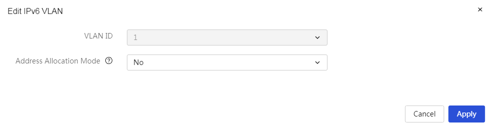

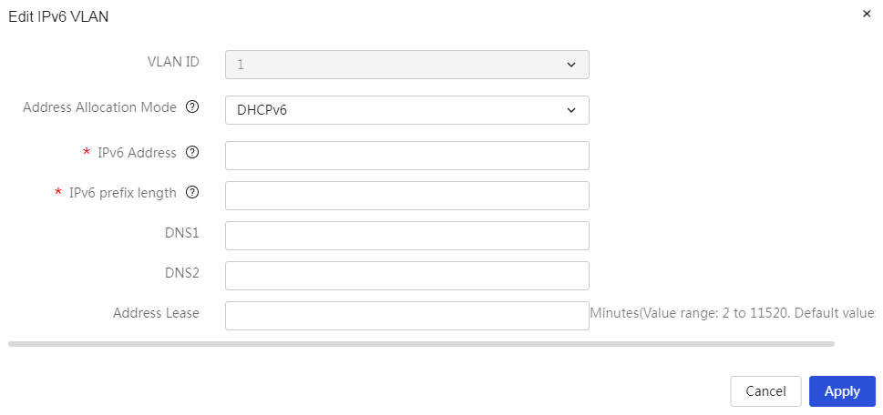
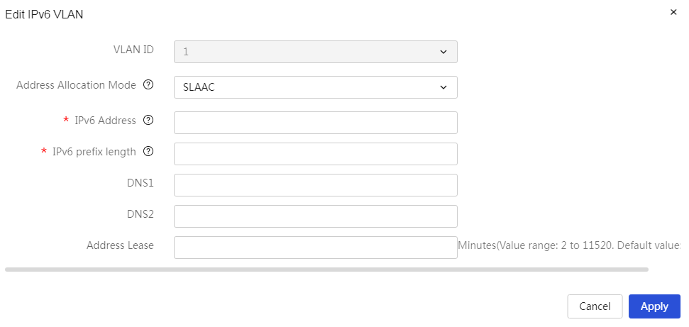

Parameters
Table 31 Parameter description
|
Item |
Description |
|
VLAN ID |
The ID number of this VLAN interface. |
|
Address allocation method |
The method for the device to obtain an IPv6 address, options include: · None: No IPv6 address configuration. · Automatic: Allocate IPv6 addresses using both DHCPv6 and SLAAC methods. ¡ IPv6 Address: The IPv6 address assigned to this VLAN interface. ¡ IPv6 Prefix Length: The prefix length of the IPv6 address, ranging from 48 to 64. ¡ DNS1 and DNS2: Input the DNS server addresses for accessing the wide area network (WAN). Note that the device prioritizes using DNS1 for domain name resolution. If resolution fails, it will use DNS2 for domain name resolution. ¡ Address Lease: The lease time for the IPv6 address. · DHCPv6: The device obtains an IP address from the DHCPv6 server. When selecting this option, a DHCPv6 server must exist in the network environment for dynamic allocation of IPv6 addresses. ¡ IPv6 Address: The IPv6 address assigned to this VLAN interface. ¡ IPv6 Prefix Length: The prefix length of the IPv6 address, ranging from 48 to 64. ¡ DNS1 and DNS2: Input the DNS server addresses for accessing the wide area network (WAN). Note that the device prioritizes using DNS1 for domain name resolution. If resolution fails, it will use DNS2 for domain name resolution. ¡ Address Lease: The lease time for the IPv6 address. · SLAAC: Automatically configures the IPv6 address based on the device's link-layer address and the prefix information published by the router. ¡ IPv6 Address: The IPv6 address assigned to this VLAN interface. ¡ IPv6 Prefix Length: The prefix length of the IPv6 address, ranging from 48 to 64. ¡ DNS1 and DNS2: Input the DNS server addresses for accessing the wide area network (WAN). Note that the device prioritizes using DNS1 for domain name resolution. If resolution fails, it will use DNS2 for domain name resolution. ¡ Address Lease: The lease time for the IPv6 address. · DHCPv6-PD: Generates the interface's IPv6 address after obtaining a prefix from the specified WAN interface. ¡ Subnet Prefix Name: The identifying name of the subnet, which can specify from which WAN interface to obtain the prefix, defaulting to all interfaces. ¡ Subnet Prefix Length: Specifies the length of the subnet mask to define the subnet range, ranging from 48 to 64. ¡ Subnet ID: Specifies the identifier (ID) of a specific subnet. ¡ DNS1 and DNS2: Input the DNS server addresses for accessing the wide area network (WAN). Note that the device prioritizes using DNS1 for domain name resolution. If resolution fails, it will use DNS2 for domain name resolution. ¡ Address Lease: The lease time for the IPv6 address. |
|
Link-local address |
Dedicated IPv6 addresses for communication within the same network link. |
|
Task |
You can edit and delete this configuration. |
Configure static DHCPv6
About this task
To allocate a fixed IPv6 addresses to a client, perform this task to bind the client's DUID to the IPv6 address.
Procedure
Page Wizard: [Network Settings/IPv6 Configuration/Static DHCPv6]
|
This page provides you with the following main functions: · Display detailed information about the added DHCPv6 static binding relationships · Add a DHCPv6 static binding relationship · Delete a DHCPv6 static binding relationship · Modify an added DHCPv6 static binding relationship |
|
|
Add a DHCPv6 static binding relationship: 1. Click the < Add > button to pop up the Add DHCPv6 dialog box, and set the parameters for the interface, IPv6 suffix, and DUID 2. Click the < Acknowledge > button to complete the configuration |
|
|
Delete an added DHCPv6 static binding relationship: 1. Select the radio box in front of the DHCPv6 static binding relationship you want to delete 2. Click the < Delete > button to pop up the confirmation prompt dialog box, then click the < Acknowledge > button to complete the configuration |
|
|
Modify an added DHCPv6 static binding relationship: 1. Click the edit icon in the operation column corresponding to the DHCPv6 static binding relationship you want to modify, which will pop up the DHCP static binding relationship dialog box, and modify the relevant configuration items 2. Click Apply. |
|
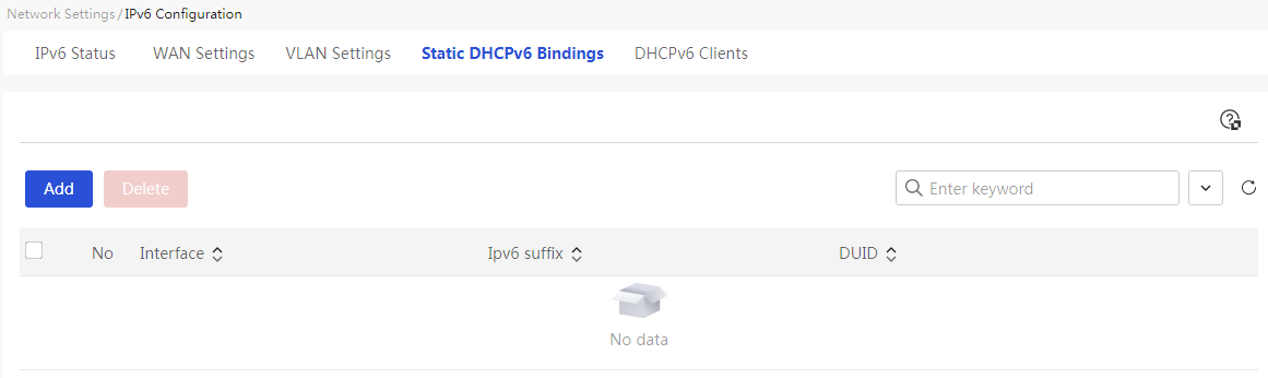
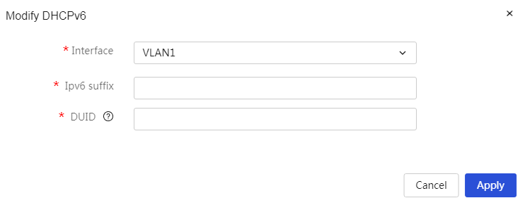
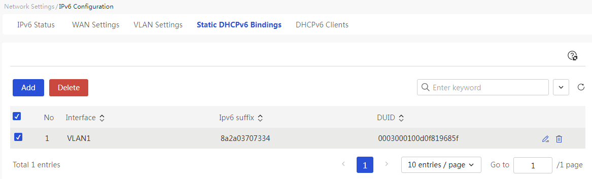

Parameters
Table 32 Parameter description
|
Item |
Description |
|
No. |
The ID number of the VLAN interface. |
|
Ports |
The VLAN interfaces created on the device. |
|
IPv6 suffix |
The interface identifier that generates the IPv6 address together with the IPv6 prefix, which is the IPv6 suffix. |
|
DUID |
The client's unique identifier (DHCP Unique Identifier) used to distinguish different devices. |
View DHCPv6 client information
About this task
After the DHCPv6 server allocates IPv6 addresses to DHCPv6 clients through either dynamic allocation or static binding, you can view information about the IPv6 addresses assigned to DHCPv6 clients.
Procedure
Page Wizard: [Network Settings/IPv6 Configuration/DHCPv6 Client]
|
Display the details of the device allocated by DHCP |
|
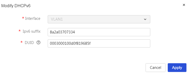
Parameters
Table 33 Parameter description
|
Item |
Description |
|
No. |
Number of DHCPv6 allocation information. |
|
DHCPv6 service |
VLAN interface on the device where DHCPv6 service is enabled. |
|
IPv6 address. |
IPv6 address allocated to the client device. |
|
DUID |
Unique identifier of the client, used to distinguish different devices. |
|
Validity Time |
Remaining valid time of the address lease, in seconds. |
Configure address groups
About this task
An address group is a collection of host names or IP addresses. Each address group can contain several members, which can be IP addresses or IP address ranges. If your certain services (e.g., bandwidth management) require using address groups to identify user packets, you need to configure address groups that meet business needs in advance.
Restriction and guidelinks
1. An address group can contain only IPv4 addresses.
2. The start address in an IP address range must be lower than the end address.
3. An address range can contain a maximum of 256 IP addresses and make sure all the IP addresses in the address range are valid.
Procedure
Page Wizard: [Network Settings/Address Group]
|
This page provides you with the following main functions: · Display details of the added address groups · Add address groups · Delete added address groups · Modify added address groups |
|
|
Add address group: 1. Click the <Add> button to open the Add Address Group dialog box. Enter the name, description, IP address, and other parameter information for the address group. 2. Click the <OK> button to complete the configuration. |
|
|
Delete added address groups: 1. Select the radio box in front of the address group you want to delete. 2. Click the <Delete> button to open the confirmation dialog, then click the <OK> button to complete the configuration. |
|
|
Modify added address groups: 1. Click the edit icon in the operation column corresponding to the address group you want to modify, which will open the modify address group dialog box to change the relevant configuration items. 2. Click Apply. |
|
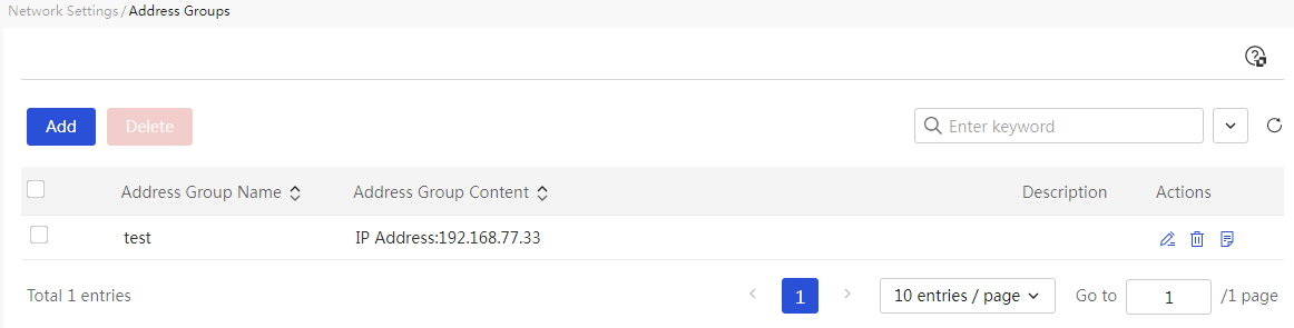
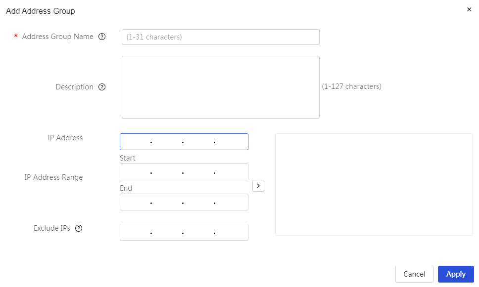
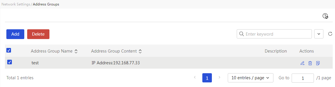
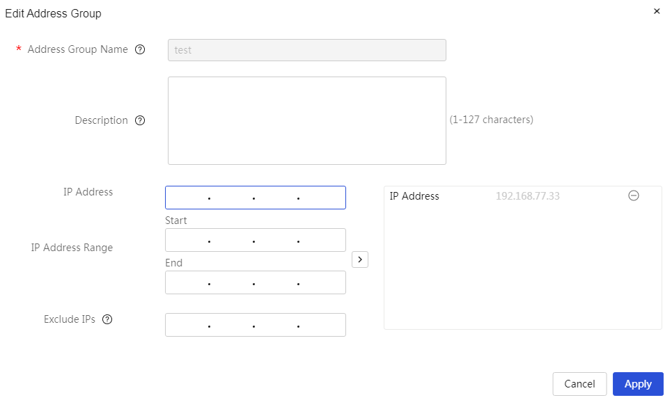
Parameters
Table 34 Parameter description
|
Parameter |
Description |
|
Address Group Name |
A name for a set of user host names or IP addresses. When configuring this parameter, the name can indicate the characteristics of the addresses in this address group. The address group name cannot be named 'any' (case-sensitive). |
|
Description |
Description of the address group, providing a simple description for easier use. |
|
IP address |
A single IP address to be added to the address group. When configuring this parameter, after entering the IP address, click the “>” button on the right side of the configuration item (CI) to submit the configured address pool content. |
|
IP Range |
A range of IP addresses to be added to the address group. When configuring this parameter, after entering the starting and ending IP addresses, click the “>” button on the right side of the configuration item (CI) to submit the configured address pool content. |
|
Excluded addresses |
IP addresses that need to be excluded from the address group. When configuring this parameter, after entering the exclusion address, click the “>” button on the right side of the configuration item (CI) to submit the configured address pool content. |
|
Task |
This configuration can be edited, deleted, and viewed in detail. |
Configure time range groups
About this task
For some features (for example, bandwidth management or network behavior management) to take effect only during the specified time period, you can create a time range group and reference it when configuring such features.
A time group can configure one or more time ranges. The effective time for the time range has the following two methods:
· Periodic Effect: Cycles weekly, for example, every Monday from 8 to 12.
· Non-Periodic Effect: Effective within a specified time range, for example, from January 1, 2015, to January 3, 2015, daily from 8 AM to 6 PM.
Restriction and guidelinks
1. You can create a maximum of 64 time range groups.
2. A time range group can contain a maximum of 16 recurring time ranges and a maximum of 16 non-recurring time ranges.
Procedure
Page Wizard: [Network Settings/Time Group]
|
This page provides you with the following main functions: · Display detailed information of the added time groups · Add time groups · Delete added time groups · Modify added time groups |
|
|
Add time groups: 3. Click the <Add> button to open the New Time Group dialog box, and enter the name and effective time of the time group. 4. Click the <OK> button to complete the configuration. |
|
|
Delete added time groups: 1. Select the radio box in front of the time groups you want to delete 2. Click the <Delete> button to open the confirmation prompt dialog box, then click the <OK> button to complete the configuration. |
|
|
Modify added time groups: 1. Click the edit icon in the corresponding operation column of the time group you want to modify, pop up the modify time group dialog box, and change the relevant configuration items (CIs) 2. Click Apply. |
|
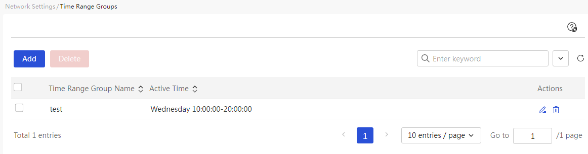
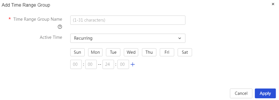
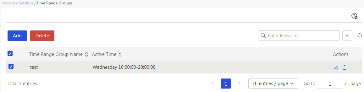
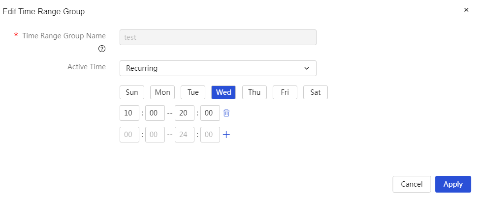
Parameters
Table 35 Parameter description
|
Parameter |
Description |
|
Time Group Name |
The name for a specific time period. When configuring this parameter, the name can help users understand the characteristics of the time period. The time group name cannot be named 'any' (case-sensitive). |
|
Effective At |
The effective time for this time group can be set in two ways: · Periodic Effectiveness: Effective on a weekly cycle. When configuring this parameter, select the specific days of the week on which it should be effective, and enter the specific effective times for each day below. Click the <+> button, then click the <Confirm> button to complete the configuration for this time period. · Non-Periodic Effectiveness: Effective within a specified time range. When configuring this parameter, select the start and end dates for effectiveness, and enter the specific start and end times below. Click the <+> button, then click the <Confirm> button to complete the configuration for this time period. |
|
Task |
This configuration can be edited or deleted. |
Configure network behavior management
Configure bandwidth management
Introduction
The bandwidth management function is used to manage traffic. Administrators can perform fine control over user traffic based on conditions such as address groups and time groups.
Configure rate limiting
About this task
Manage bandwidth for specified interfaces or users.
Restriction and guidelinks
Before configuring IP rate limiting, please first set the upstream and downstream bandwidth for the link on the "WAN Configuration" tab in the [Network Settings/External Network Configuration] page. If not pre-configured, you can also click the "Set" link in the "Traffic Limitation" configuration item to go to the WAN configuration page to set the current link's upstream and downstream bandwidth.
Procedure
Page Wizard: [Internet Behavior Management/Bandwidth Management/IP Rate Limiting]
|
This page provides you with the following main functions: · Display detailed information about the added IP traffic control · Add IP traffic control · Delete added IP traffic control · Modify added IP traffic control |
|
|
Add IP traffic control policy: 1. Click<Add> button to pop up the add IP traffic control policy dialog box, and set parameters such as application interface, user range, traffic limit, and restriction time period. 2. Click<OK> button to complete the configuration. |
|
|
Delete added IP traffic control: 1. Select the radio box in front of the IP traffic control you want to delete. 2. Click<Delete> button to pop up a confirmation prompt dialog box, then click<OK> button to complete the configuration. |
|
|
Modify added IP traffic control: 1. Click the edit icon in the operation column corresponding to the IP traffic control you want to modify, which will pop up the modify IP traffic control dialog box to change the relevant configuration items. 2. Click Apply. |
|
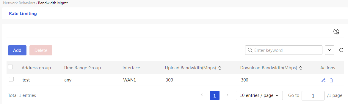
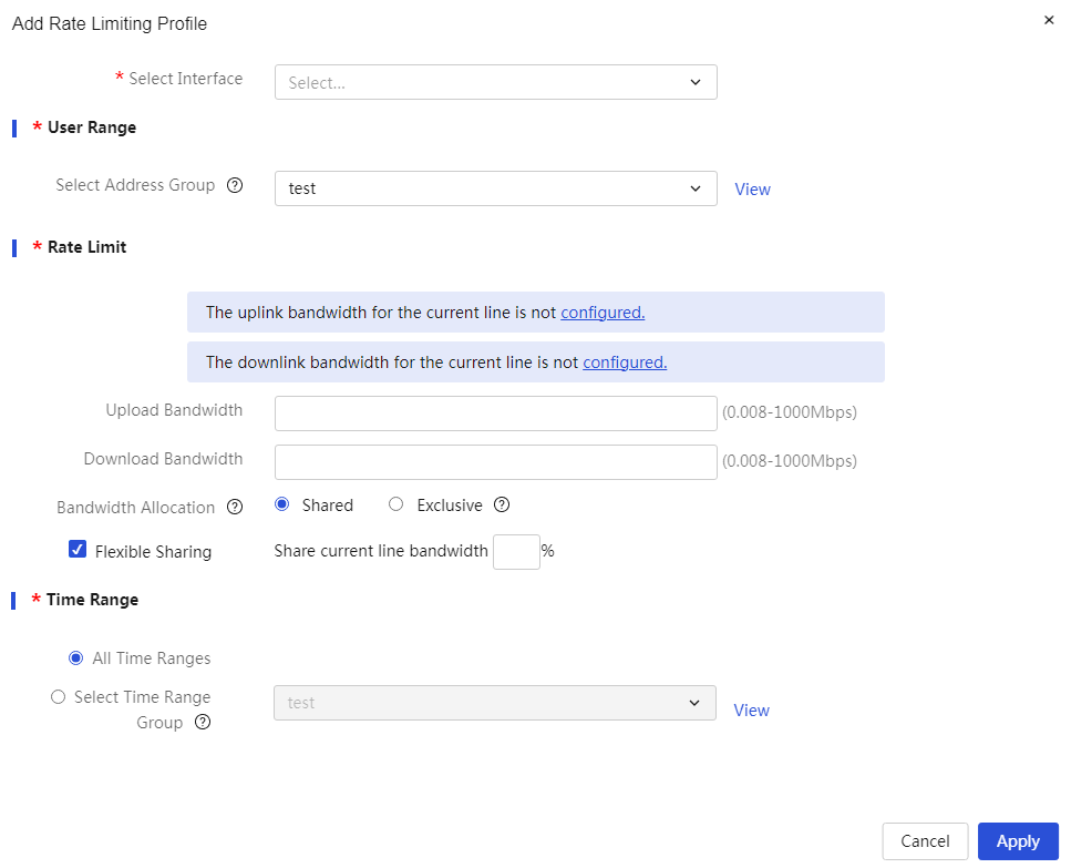
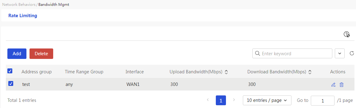
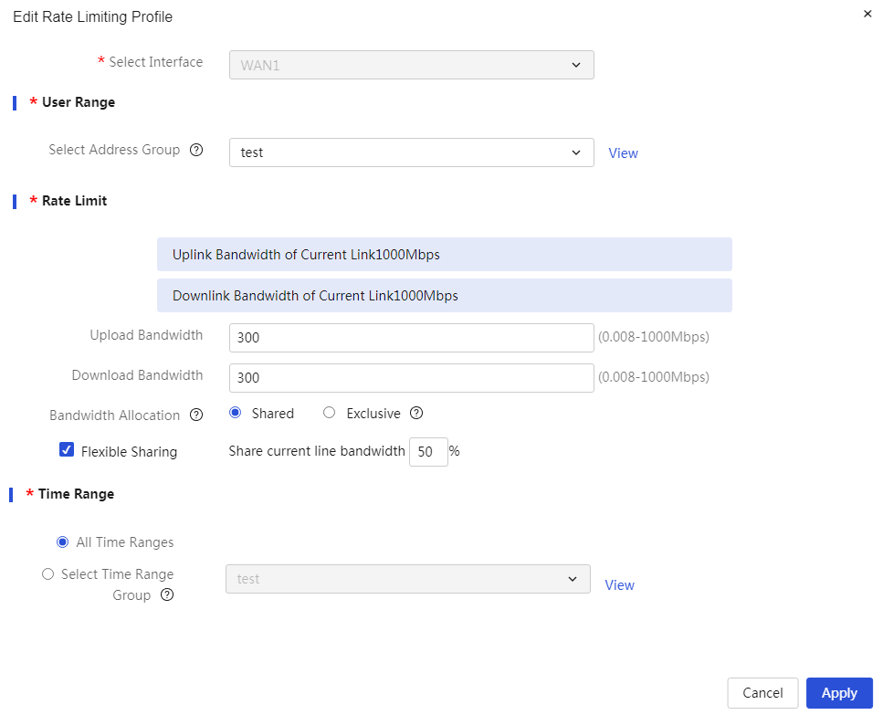
Parameters
Table 36 Parameter description
|
Parameter |
Description |
|
Application Interface |
The source interface of the message, where the rules control the data packets received from a specific interface. |
|
User |
The address group that the rules need to control. When configuring this parameter, you must select an existing address group. To add a new address group, you can create it by clicking the <Add Address Group> button on the right. |
|
Upload Bandwidth |
The maximum upload bandwidth value for users within the address group. The unit is Mbps. Before configuring this parameter, you need to set the current link's upload bandwidth based on the actual upstream bandwidth provided by the carrier. |
|
Download Bandwidth |
The maximum download bandwidth value for users within the address group. The unit is Mbps. Before configuring this parameter, you need to set the current link's download bandwidth based on the actual upstream bandwidth provided by the carrier. |
|
Traffic Allocation |
The method of traffic allocation: mainly divided into: · Shared: All computers in the specified address group share the given bandwidth. · Exclusive: Each computer in the specified address group occupies the given bandwidth (i.e., traffic upper limit) individually. |
|
Flexible Sharing |
When the user's actual traffic bandwidth exceeds the configured bandwidth limit, the maximum percentage of the current link's upstream and downstream bandwidth that can be shared. When the traffic allocation is set to shared, this parameter can be configured as needed. |
|
Restriction Time Period |
The effective time period for IP speed limiting. When configuring this parameter, you can choose: · All Time Periods · Select an existing time group. To add a new time group, you can create it by clicking the <Add Time Group> button on the right. |
|
Task |
You can edit and delete this rule. |
Configure network behavior management
Introduction
The internet behavior management function performs fine control over users' internet behavior based on conditions such as address groups, time groups, and applications.
Configure URL control
About this task
Perform this task to allow users to access or prevent users from accessing the specified URLs.
Restriction and guidelinks
1. After enabling the URL denylist mode, the device will prohibit specified users from accessing websites specified in the custom URL category during the designated time period; websites not in the URL category can be accessed normally.
Assuming the administrator creates a URL denylist with the name URL Group A and an address group named User Group A. The matching rules for users are as follows:
¡ If user User1 belongs to User Group A, then user User1 is not allowed to access URLs in URL Group A;
¡ If user 2 does not belong to user group A, user 2 can access any URLs.
2. After enabling the URL allowlist mode, the device only allows specified users to access websites specified in the custom URL category during the designated time period; websites not in the URL category cannot be accessed.
Suppose you create the following allowlists:
¡ URL allowlist A: The URL category is URL group A and the address group is user group A.
¡ URL allowlist B: The URL category is URL group B and the address group is user group B.
The match rules are as follows:
¡ If user User1 belongs to both User Group A and User Group B, then user User1 is only allowed to access URLs in URL Group A and URL Group B;
¡ If user User2 only belongs to User Group A, then user User2 is only allowed to access URLs in URL Group A.
¡ If user User3 belongs neither to user group A nor to user group B, then user User3 is not allowed to access any URLs.
3. If the IE browser is used to export custom URLs and Excel fails to be started, edit the browser settings as follows:
Select Tools > Internet Options, click the Security tab, and then click Custom level. Under ActiveX controls and plug-ins, select Enable for Initialize and script ActiveX controls not marked.
4. When configuring URL keywords, if exact match is required, the keyword should not include wildcard *, for example, www.baidu.com; if fuzzy match is required, the keyword should include wildcard *, for example, *.baidu.com, www.baidu*, or *baidu*; if all URLs need to be configured, the keyword should be set to *.*. Note that wildcards cannot be configured in the middle of a character string or consist solely of wildcards, such as aaa*11 and *, as this will cause the configuration to fail.
Procedure
Page wizard: [Internet Behavior Management/Internet Behavior Management/URL Control]
|
This page provides you with the following main functions: · Enable URL denylist and allowlist mode · Configure custom URL categories · Delete added URL categories · Import custom URL list |
|
|
Enable URL denylist and allowlist mode: 1. Select the “URL denylist mode” or “URL allowlist mode” option 2. Click the <OK> button to complete the configuration |
|
|
Configure custom URL categories: 1. Set the custom URL category name, address group, and time group 2. Click the details icon corresponding to the new URL category to open the set URL keywords dialog box. Configure the URL keywords 3. Click the <OK> button to complete the configuration |
|
|
Delete added URL categories: 1. Select the URL category to delete and click the <Delete> button 2. A confirmation dialog box will pop up. Click the <OK> button to complete the configuration |
|
|
1. Import custom URL list 2. Click the import icon corresponding to the new URL category to open the import custom URL list dialog box. Click the <Upload File> button and select the custom URL list to import 3. Click the <OK> button to complete the configuration |
|
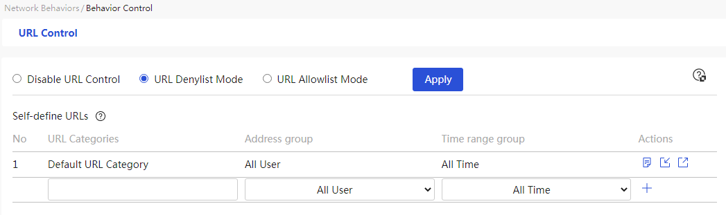
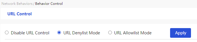

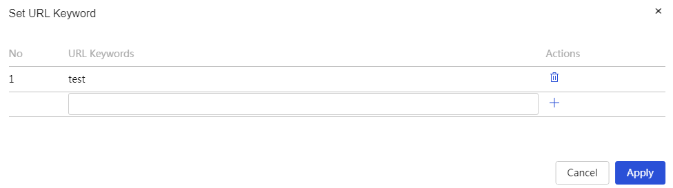
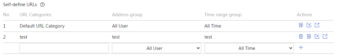

Parameters
Table 37 Parameter description
|
Parameter |
Description |
|
URL Allowlist |
If this function is enabled, the device allows specified users to access designated URLs within the custom URL category during specified time periods; URLs not in the category cannot be accessed. |
|
URL Denylist |
If this function is enabled, the device prohibits specified users from accessing designated URLs within the custom URL category during specified time periods; URLs not in the category can be accessed normally. |
|
No. |
Number of the URL Control Policy |
|
URL Categories |
URL Keyword Dialog Box. Enter the corresponding URL, click the <+> button on the right, and the URL will be added successfully. Click the <OK> button to complete adding the URL keyword. |
|
Configure address groups |
IP address group that the policy needs to control. |
|
Configure time range groups |
Effective time of the policy |
|
Task |
You can perform the following operations on this policy: · Delete: Remove this policy · Details: Set URL keywords · Import: If there are too many custom URL category policies, you can first export the custom URL list in CSV format, fill in the policy, and then import it back into the device. · Export: Export the custom URL list in CSV format |
|
URL Keyword |
Keywords for the policy's URLs. Click the details icon in the operation column corresponding to the URL control policy, and in the pop-up set URL keywords dialog box, you can set the URL keywords. The range is 1-63 characters, and you can enter letters, digits, and special characters (excluding / \'"<>;&`: and spaces). Letters are case-insensitive. If the keyword does not include the wildcard *, the URL control policy will perform an exact match based on the keyword, such as www.baidu.com; if the keyword includes the wildcard *, the URL control policy will perform a fuzzy match based on the keyword, such as *.baidu.com, www.baidu*, or *baidu*; if the keyword is set to *.*, it matches all URLs. |
Audit logs
Introduction
This feature allows you to audit logs of the application control and URL control functions and send the logs to the specified server.
URL filter logs
About this task
Perform this task to audit logs of the URL control function.
Restriction and guidelinks
To enable URL filter log auditing, first enable URL control.
Procedure
Page wizard: [Internet Behavior Management/Audit Logs/URL Filtering Logs]
|
Select the “Enable URL Filtering Log” option to activate the URL filtering log auditing function. |
|
|
Click the <Clear Logs> button, and in the confirmation prompt, click the <Yes> button to clear all application audit logs. |
|
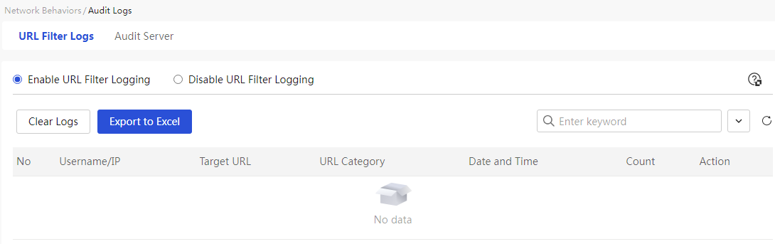
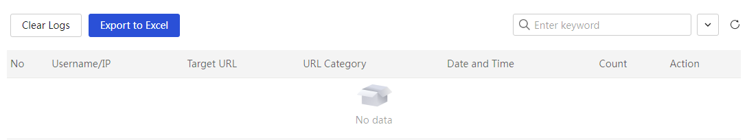
Parameters
Table 38 Parameter description
|
Parameter |
Description |
|
No. |
Log Information Number |
|
Username/IP Address |
Username or IP address that triggered the application control rule |
|
Target URL |
URL prohibited from access in the filtering rule |
|
URL Category |
Category to which the target URL belongs, e.g., search portal |
|
Date and Time |
Date and specific time when the log was generated |
|
Use License Upon Login |
Total number of logs generated |
|
Actions |
Execution actions of the application control policy on the messages that need control, mainly divided into: · Block: Indicates that the policy denies the message from passing and logs the action · Allow: Indicates that the policy permits the message to pass and logs the action |
Audit server
About this task
Perform this task to configure an audit server to send audit logs.
Restriction and guidelinks
Make sure the IP address of the audit server can communicate with the IP address of the device.
Procedure
Page wizard: [Internet Behavior Management/Audit Logs/Audit Server]
|
Set up the audit server: 1. Enable the function to send audit logs to the server, and set the audit server address and port number. 2. Click the <Apply> button to complete the configuration. |
|
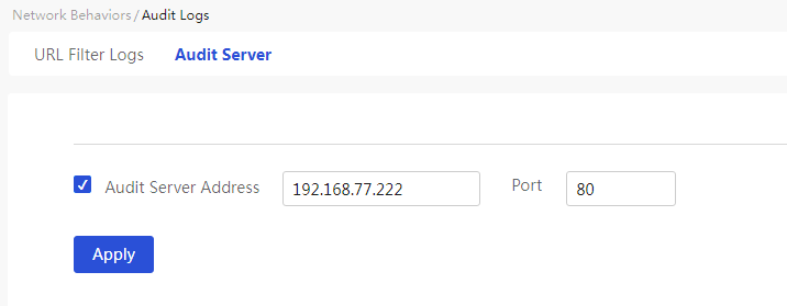
Parameters
Table 39 Parameter description
|
Parameter |
Description |
|
Audit server |
Specify the server that will |
|
Audit Server Address |
The IP address or domain name of the server for the audit logs. |
|
Port |
The |
Configure network security
Firewall
About this task
This feature allows you to configure firewall settings for network security protection. The firewall matches packets in the network based on a series of security rules to block invalid packets and forward valid packets.
Restriction and guidelinks
· After a packet matches a firewall security rule, it will no longer match other rules. To avoid incorrect packet filtering actions because of security rule matching errors, set the priorities for security rules to appropriate values.
· If the default filtering rule is Permit, you do not need to configure any security rules. All internal network endpoints connecting to the device can access each other and the external network.
· If the default filtering rule is Permit, you can
restrict the access permissions for specific internal network endpoints:
To deny specific internal network endpoints in a VLAN from accessing the
external network, configure a deny security rule between the corresponding VLAN
interface and WAN interface.
To deny specific internal network endpoints in a VLAN from accessing endpoints
in another VLAN, configure a deny security rule between the corresponding VLAN
interfaces.
· If the default filtering rule is Deny and you have not configured any security rules, no internal network endpoints can access the external network and endpoints in different VLANs cannot access each other.
· When the default filtering rule is set to deny, if a user needs to allow specified terminals to access a specific external network, they must configure the security rules between the designated VLAN interface and the WAN interface according to their needs, and must configure bidirectional rules, that is, one for outbound orientation and one for inbound orientation. If the user needs to allow specified terminals to access terminals in other VLANs, they must configure the security rules between the designated local VLAN interface and the opposite VLAN interface, and bidirectional rules must also be configured.
Procedure
Page wizard: [Network Security/Firewall]
|
This page provides you with the following main functions: · Enable or disable the firewall · Set default filtering rules · Add security rules · Delete security rules · Modify existing security rules · Display information about created security rules |
|
|
Select the “Enable Firewall” radio box to enable the firewall function |
|
|
In the default filtering rule configuration item, set the default filtering rules, click the <Apply> button to save the configuration |
|
|
Add security rules: 1. Click the <Add> button to open the create security rules page and configure parameters such as interface, orientation, and precedence 2. Click Apply. |
|
|
Delete security rules: 1. Select the security rules you want to delete 2. Click the <Delete> button to open the prompt dialog box 3. Click Apply. |
|
|
Modify security rules: 1. Click the edit icon in the operation column of the security rule you want to modify to open the modify security rule dialog box and change the relevant parameters 2. Click Apply. |
|
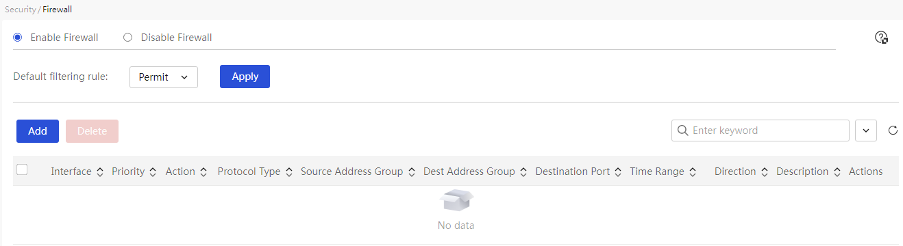

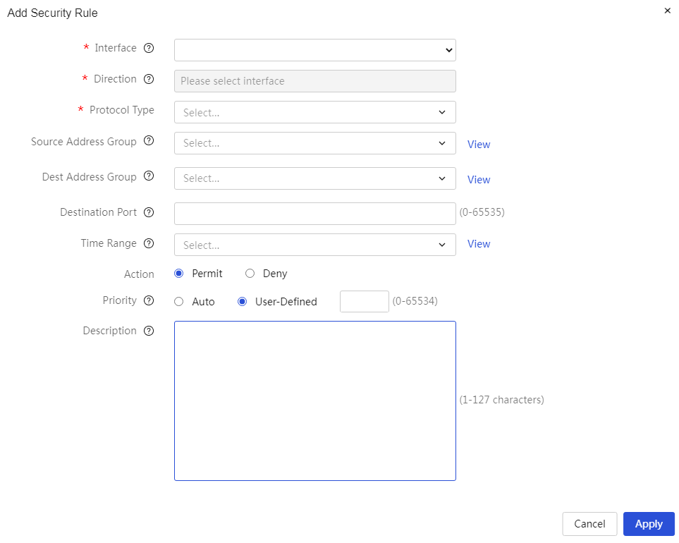
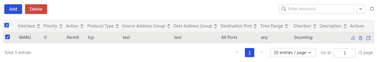
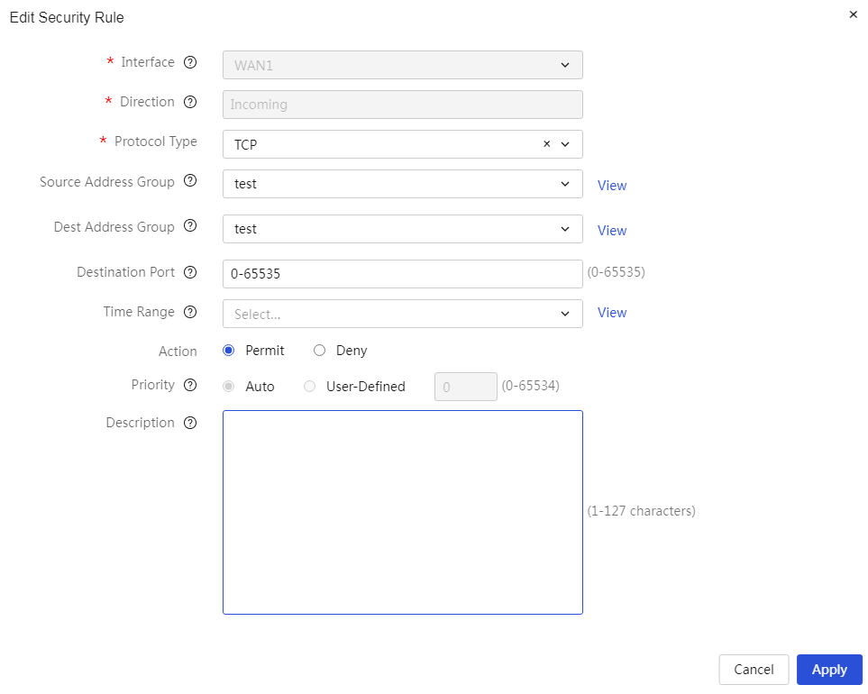
Parameters
Table 40 Parameter description
|
Parameter |
Description |
|
Enable Firewall |
Whether to enable the firewall function. If this function is enabled, the device will operate according to the configured firewall and rules. The default is off. |
|
Default Filtering Rules |
The handling method for packets that do not match any rules, meaning the action the device takes on a packet when it does not match any rules, is mainly divided into: · Allow: Allow the packet to pass through the firewall. · Deny: Prevent the packet from passing through the firewall. After setting is complete, you need to click the “Apply” button to make the configuration effective. The default state is to allow. |
|
Ports |
The source interface of the packet, meaning the rules control the data packets received from a specific interface. |
|
Direction |
Display the direction of security rules, including inbound and outbound directions. · When the “Interface” parameter is selected as the WAN interface, the direction of security rules is inbound, meaning it controls traffic entering the device from the public network side. · When the “Interface” parameter is selected as the VLAN interface, the direction of security rules is outbound, meaning it controls traffic entering the device from the internal network side. |
|
Protocol |
Protocol type of the packets. Options include: · If you need to control packets of a specific transport layer protocol, select “TCP” or “UDP.” · If you need to control ICMP protocol packets like Ping or Tracert, select “ICMP.” · If you need to control packets of all protocols, select “All Protocols.” |
|
Source Address Group |
The range of source IP addresses that the rule needs to control. When configuring this parameter, you must select an already created address group. If you need to add a new address group, you can create a new address group by clicking the right-side < Add Address Group > button. |
|
Destination Address Group |
The range of destination IP addresses that the rule needs to control. When configuring this parameter, you must select an already created address group. If you need to add a new address group, you can create a new address group by clicking the right-side < Add Address Group > button. |
|
Dest Port Range |
The range of destination port numbers that the rule needs to control. When configuring this parameter, the starting port number cannot be greater than the ending port number. |
|
Rule Effective Time |
The effective time of the rule. When configuring this parameter, you must select an already created time group. If you need to add a new time group, you can create a new time group by clicking the right-side < Add Time Group > button. |
|
Actions |
The action the rule takes on the packets that need to be controlled is mainly divided into: · Allow: Indicates that the rule allows the packet to pass. · Deny: Indicates that the rule denies the packet from passing. |
|
Priority |
The precedence of the rule. There are two ways to set it: · Automatic: The system automatically assigns precedence to the rule, allocating it sequentially based on the configuration order in increments of 5. · Custom: The user customizes the precedence of the rule; the smaller the value, the higher the precedence. |
|
Description |
The description information of the rule, which can provide a simple description of the rule for easier use. |
|
Task |
You can edit, delete, or copy this rule. |
Connection limitation
Introduction
The connection limitation function is a security mechanism that limits the number of connections initiated by each IP address, achieving reasonable allocation of device processing resources and preventing malicious connections.
If the device detects that the number of TCP or UDP connections from a certain IP address exceeds the specified number, it will deny that connection establishment. New connections will only be allowed when the connection count falls below the limit.
Network connection limit number
About this task
The network connection limit refers to the restriction on the number of connections initiated by each IP address within a specified IP address range. This method is used to control connections received by all interfaces on the device.
Restriction and guidelinks
· Each network connection limit rule, if it is an IP address range, indicates that the maximum number of network connections that can be established by each IP within that address range will be limited to the set upper limit. If the starting address and ending address are the same, it means that the network connection limit is only for that specific IP.
· Multiple network connection limit rules can be added to the limit rule table; when configuring the rules, overlapping IP addresses among certain rules are allowed, but the priority of the earlier-added rule takes precedence. For the same IP address, the later-added network connection limit settings will not overwrite the previous settings, and the earlier configured connection limit will prevail.
· It is allowed to delete, modify, and perform other operations on previously configured rules in the limit rule table. However, modifications cannot change the priority of the rules, and the effective rules will still adhere to the conventions of rule point 2.
· Network connection rate limiting only restricts internal IPs initiating network connections to the Internet; the following situations are not within the scope of limitation: connections initiated to the device itself and to other internal IPs, as well as connections initiated from the Internet to internal IPs.
· Total connection number = TCP connection number + UDP connection number + other connection number, where other connections refer to connections other than TCP and UDP, such as ICMP, etc. The conditions for a certain IP to establish a new connection are: the number of connections already established by this IP must not exceed the set upper limit. For example, if a certain IP needs to establish a TCP connection, it must satisfy that the total number of connections already established by this IP has not reached the upper limit for total connections, and the TCP connection number has not reached the upper limit for TCP connections; the conditions for establishing UDP connections and other connections are the same as for TCP.
· Setting the TCP connection number to 0 and leaving it blank differ in that: setting it to 0 means that TCP connections are not allowed, while leaving it blank means that there is no separate restriction on the TCP connection number, but the total connection limit condition must still be met. The situation for UDP connection numbers is similar.
· Each VLAN network connection limit rule indicates that the maximum number of network connections that can be established within the specified VLAN will be limited to the set upper limit. Note that the connection limit set here refers to the upper limit of the total number of connections of all IPs within that VLAN, not each IP's individual connection limit.
· Total connection number = TCP connection number + UDP connection number + other connection number, where other connections refer to connections other than TCP and UDP, such as ICMP, etc. The conditions for a certain VLAN to establish new connections are: the number of connections already established by IPs within this VLAN must not exceed the set upper limit. For example, if an IP within a certain VLAN needs to establish a TCP connection, it must satisfy that the total number of connections already established by this VLAN has not reached the upper limit for total connections, and the TCP connection number has not reached the upper limit for TCP connections; the conditions for establishing UDP connections are similar to those for establishing TCP connections.
Procedure
Page wizard: [Network Security/Connection Limitation/Network Connection Limit Number]
|
This page provides you with the following main functions: · Enable or disable network connection limit · Add network connection limit rules · Delete network connection limit rules · Modify added network limit rules · Display information related to added network connection limit rules |
|
|
Add network connection limit rules: 1. Click the <Add> button to open the new network connection limit rule dialog box and configure the relevant parameters 2. Click the <Apply> button to complete the configuration |
|
|
Delete network connection limit rules: 1. Select the network connection limit rules to delete, click the <Delete> button, and a confirmation prompt dialog box will appear 2. Click Apply. |
|
|
Modify network connection limit rules: 1. Click the edit icon in the operation column corresponding to the network connection limit rule you want to modify, open the modify network connection limit rule dialog box, and change the relevant configuration items 2. Click Apply. |
|
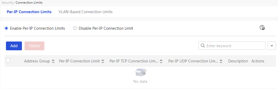
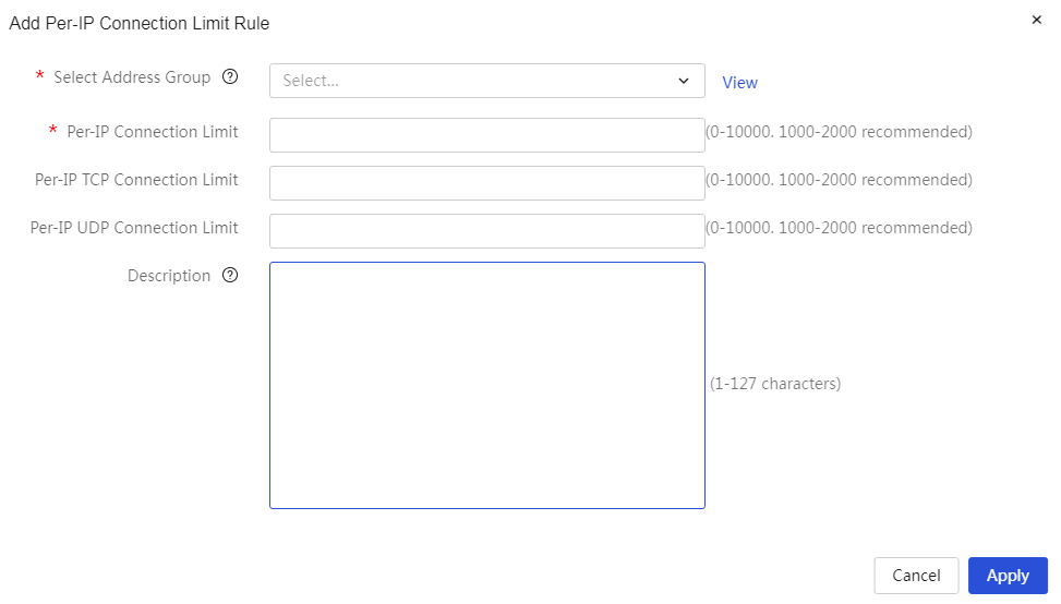
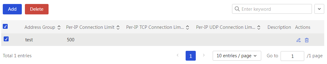

Parameters
Table 41 Parameter description
|
Parameter |
Description |
|
Enable Network Connection Limit |
Whether to enable the network connection limit function. If this function is enabled, the device will operate according to the configured network connection limit rules, which are disabled by default. |
|
Connection Limit Address Group |
IP address range that needs to be controlled by the rules |
|
Maximum Total Connections per IP |
Maximum number of network connections allowed per IP address |
|
Maximum TCP Connections per IP |
Maximum TCP network connections allowed per IP address |
|
Maximum UDP Connections per IP |
Maximum UDP network connections allowed per IP address |
|
Description |
Description of the rules, providing a simple description for ease of use |
VLAN network connection limit
About this task
VLAN network connection limit refers to the restriction on the number of connections initiated by each IP address on the specified VLAN interface. This method is used to control connections received by the specified VLAN interface.
Procedure
Page wizard: [Network Security/Connection Limitation/VLAN Network Connection Limit Number]
|
This page provides you with the following main functions: · Enable or disable VLAN network connection limit · Add VLAN network connection limit rules · Delete VLAN network connection limit rules · Edit the added VLAN network limit rules · Display information related to the added VLAN network connection limit rules |
|
|
Add VLAN network connection limit rules: 1. Click the <Add> button to open the new VLAN network connection limit rules dialog box and configure the relevant parameters 2. Click the <Apply> button to complete the configuration |
|
|
Delete VLAN network connection limit rules: 1. Select the VLAN network connection limit rules you want to delete, and click the <Delete> button to open the confirmation prompt dialog box 2. Click Apply. |
|
|
Edit VLAN network connection limit rules: 1. Click the edit icon in the operation column of the VLAN network connection limit rule you want to modify, open the edit VLAN network connection limit rules dialog box, and modify the relevant configuration items 2. Click Apply. |
|
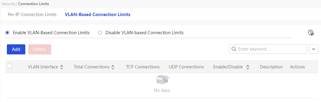

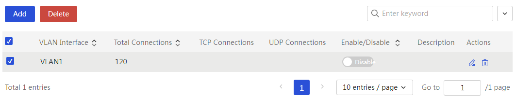
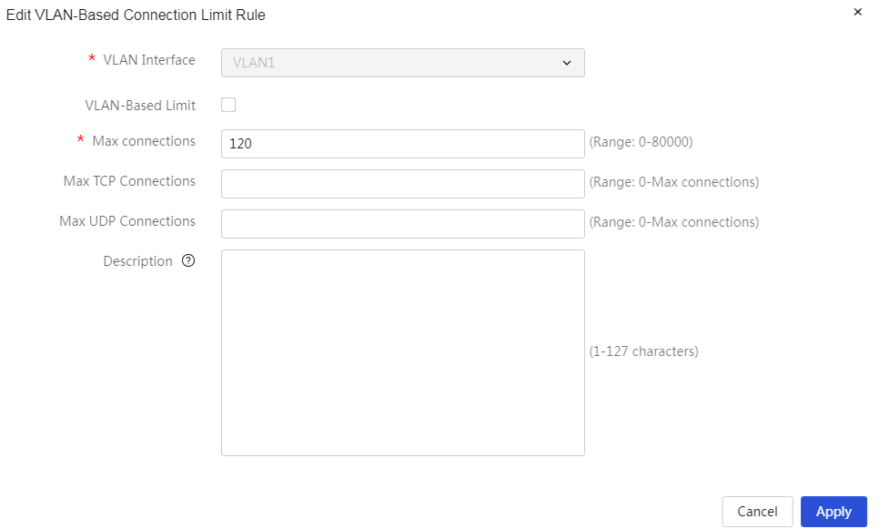
Parameters
Table 42 Parameter description
|
Parameter |
Description |
|
Enable VLAN Network Connection Limit |
Whether to enable the VLAN network connection limit function. If this function is enabled, the device will operate according to the configured VLAN network connection limit rules. By default, the VLAN network connection limit function is turned off. |
|
VLAN Interface |
The VLAN interfaces that need to be controlled by the rules |
|
Total Connection Upper Limit |
The maximum number of network connections allowed for the specified VLAN interface, to prevent individual VLANs from consuming excessive resources |
|
TCP Connection Upper Limit |
The maximum number of TCP network connections allowed to be initiated by the specified VLAN interface |
|
UDP Connection Upper Limit |
The maximum number of UDP network connections allowed to be initiated by the specified VLAN interface |
|
Description |
Description of the rules, allowing for a simple description of the rules for ease of use |
MAC filter
Introduction
If you wish to restrict packets coming from certain devices (allow or deny their passage), you can configure the MAC address filtering function on the VLAN interface. After enabling the MAC address filtering function, it will filter the source MAC addresses of received packets based on the MAC denylist and allowlist.
The filtering methods are as follows:
· Allowlist: Only source MAC addresses in the allowlist are permitted to access the external network; others are denied access.
· Denylist: Only source MAC addresses in the denylist are prohibited from accessing the external network; others are allowed access.
MAC filtering settings
Restriction and guidelinks
· If you need to enable the MAC address filtering function on the interface connected to the administrator's terminal, please ensure that the administrator's terminal MAC address has been added to the allowlist or has not been added to the denylist.
· English characters in MAC addresses are case-insensitive.
Page wizard: [Network Security/MAC Address Filtering/MAC Filtering Settings]
|
Set MAC address filtering: 1. Select the "allowlist" or "denylist" option in the "Filtering Method" column for the specified interface, and select the "Enable" option in the "On and Off" column. 2. Click the <Apply> button to complete the configuration. |
|
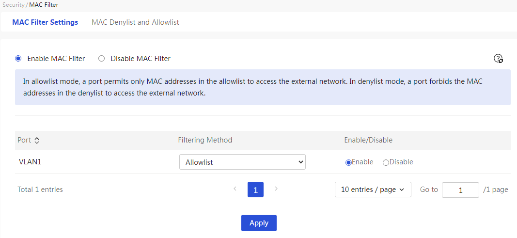
Parameters
Table 43 Parameter description
|
Parameter |
Description |
|
Port |
Interface for Matching MAC Address Filtering Policy |
|
Filtering Method |
The method for the device to filter MAC addresses is mainly divided into: · Allowlist: Only allows source MAC addresses within the allowlist to access the internet, while others are denied access. · Denylist: Only prohibits source MAC addresses within the denylist from accessing the internet, while others are allowed access. |
|
Enable and Disable |
Whether to enable the MAC address filtering function: · If this function is enabled, the device will control the access of internal LAN computers to the internet based on the MAC addresses in the MAC address list. · If this function is not enabled, all computers in the local area network can access the internet without restrictions. |
MAC allowlist and denylist management
About this task
Add or delete entries from the allowlist.
Configure allowlist
Page wizard: [Network Security/MAC Address Filtering/MAC Filtering Settings/MAC Allowlist and Denylist Management/Allowlist]
|
This page provides you with the following main functions: · Display detailed information of MAC addresses added to the allowlist · Add a single MAC address to the allowlist · Batch add MAC addresses to the allowlist · Add MAC addresses from the ARP entry to the allowlist · Export all MAC addresses currently added to the allowlist · Delete MAC addresses that have been added to the allowlist · Modify MAC addresses that have been added to the allowlist |
|
|
Add a single MAC address to the allowlist: 1. Click the <Add> button to open the Add Source MAC Address dialog box, then enter the MAC address and description you want to add. 2. In the dialog box that opens, click OK. |
|
|
Batch add MAC addresses to the allowlist: 1. Click the <Export> button and select the “Export Template” menu item. 2. Open the downloaded template, add the source MAC addresses to be filtered, and save it locally. 3. Click the <Import> button to open the Import Source MAC Address dialog box. 4. Click the <Upload File> button to open the dialog box for selecting the file to load, and select the edited template. 5. Click the <OK> button to complete the batch addition of MAC addresses to the allowlist. |
|
|
Import MAC addresses from ARP entries: 1. Click the <Import from ARP Entries> button to open the Import ARP MAC Table dialog box. 2. Select the MAC addresses to import and then click the <Import> button, which opens a confirmation dialog box. 3. In the dialog box that opens, click OK. |
|
|
Export all MAC addresses currently added to the allowlist: 1. Select all entries 2. Click the <Export> button and select the “Export All Data of Selected Filtering Mode” menu item. |
|
|
Delete MAC addresses that have been added to the allowlist: 1. Click the radio box in front of the MAC address you want to delete 2. Click the <Delete> button, which opens a confirmation dialog box. Click the <OK> button to complete the configuration. |
|
|
Modify MAC addresses that have been added to the allowlist: 1. Select the edit icon in the operation column corresponding to the MAC address you want to modify, which opens the Edit Source MAC Address dialog box to modify the relevant configuration items. 2. Click Apply. |
|
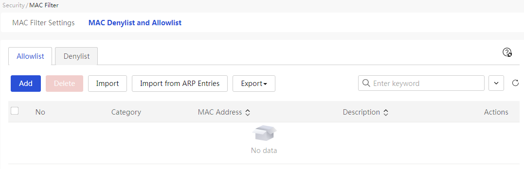
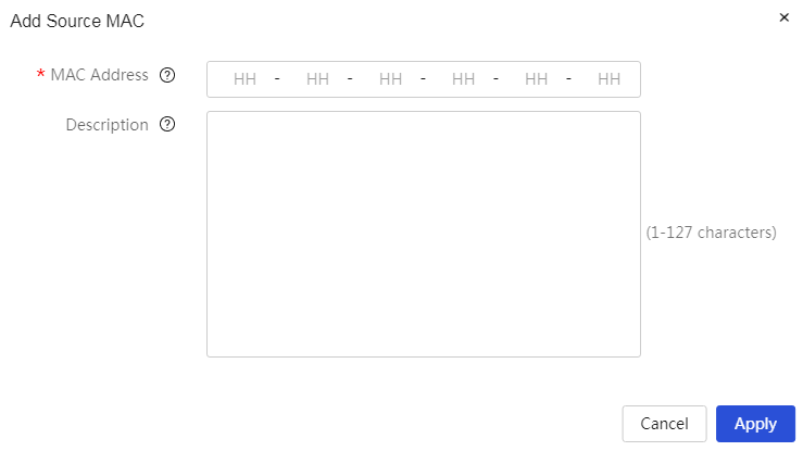

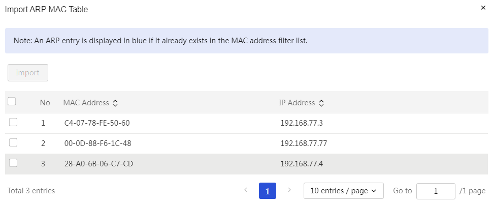
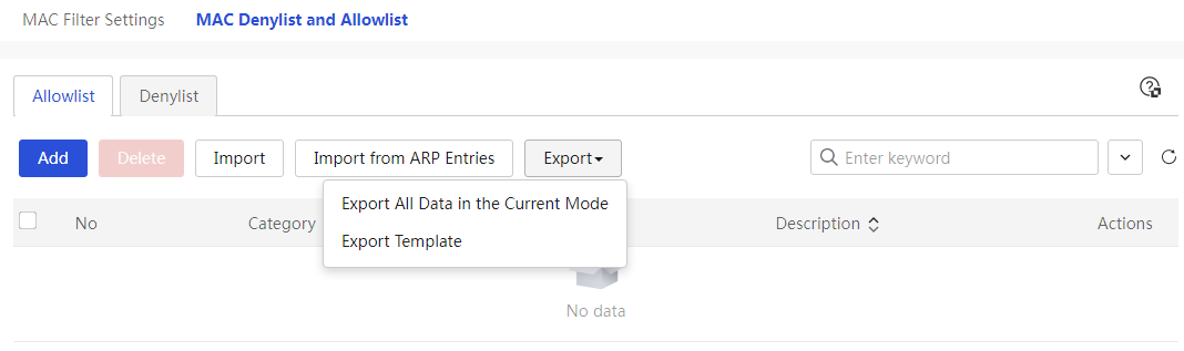
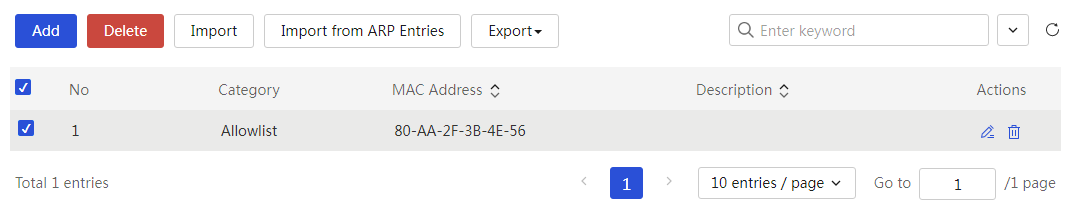

Parameters
Table 44 Parameter description
|
Parameter |
Description |
|
No. |
Policy number for MAC denylist and allowlist management |
|
Type |
Categories of MAC address filtering policies, mainly divided into: · Allowlist: Only source MAC addresses within the allowlist are allowed to access the external network; all others are prohibited from access · Denylist: Only source MAC addresses within the denylist are prohibited from accessing the external network; all others are allowed access |
|
MAC |
MAC addresses that the policy needs to control. This does not support MAC addresses of all 0s or all Fs |
|
Description |
Description information for the policy, allowing for a simple description of the policy for ease of use |
|
Task |
Allows editing and deletion of the added policies |
Denylist
Page wizard: [Network Security/MAC Address Filtering/MAC Filtering Settings/MAC Allowlist and Denylist Management/Denylist]
The configuration steps and Parameter for the denylist are similar to those for the allowlist; please refer to the denylist for configuration, and no further description is provided here.
ARP security
Introduction
The ARP protocol itself has defects, and attackers can easily exploit these defects to launch attacks. ARP attack defense technologies provide various methods to prevent, detect, and resolve ARP attacks and ARP viruses in local area networks.
ARP learning management
About this task
This function supports enabling and disabling the learning function of dynamic ARP entries on the interface. When the dynamic ARP entry learning function is disabled on the interface, it will no longer learn new dynamic ARP entries, enhancing security. When a certain interface of the device has learned all legitimate users' ARP entries, it is recommended to disable the dynamic ARP entry learning function.
Procedure
Page wizard: [Network Security/ARP Security/ARP Learning Management]
|
In the "ARP Learning Management" column of the specified interface, set whether to allow the interface to learn dynamic ARP entries. |
|
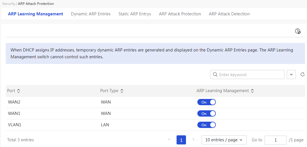
Parameters
Table 45 Parameter description
|
Parameter |
Description |
|
Port |
Interfaces, such as WAN1, VLAN1 |
|
Port type |
The interface types of the device are mainly divided into WAN and LAN ports |
|
ARP Learning Management |
The learning function of dynamic ARP entries is mainly divided into: · Enabled: Allows the interface to learn dynamic ARP entries · Disabled: Does not allow the interface to learn dynamic ARP entries When the device has learned all valid user ARP entries under a certain interface, it is recommended to disable the dynamic ARP entry learning function. Dynamic ARP entries are temporarily generated when DHCP assigns IP addresses, and these entries will appear on the dynamic ARP management page, unaffected by the on-off control of the interface's ARP learning management. |
Dynamic ARP management
About this task
This function includes dynamic ARP entry management and ARP scanning and solidification functions. The ARP scanning and solidification function automatically scans users within the local area network and solidifies the generated dynamic ARP entries into static ARP entries. It is recommended to configure this function in stable small networks (like Internet cafes). Configure the ARP scanning and solidification function first, then disable the dynamic ARP entry learning function to prevent the device from learning incorrect ARP entries.
Procedure
Page wizard: [Network Security/ARP Security/Dynamic ARP Management]
|
This page provides you with the following main functions: · Display dynamic ARP information for a specified interface · Delete specified dynamic ARP · Scan for dynamic ARP within a specified interface and IP address range · Stabilize dynamic ARP |
|
|
Delete specified dynamic ARP: 1. Select the specified option in the dynamic ARP list, click the <delete> button, and a confirmation dialog box will pop up 2. Click Apply. |
|
|
Scan for dynamic ARP within a specified interface and IP address range: 1. Click the <scan> button to open the scan dialog box, select the specified interface, and enter the specified IP address range 2. Click Apply. |
|
|
Stabilize the specified dynamic ARP: 1. Select the specified option in the dynamic ARP list 2. Click the <stabilize> button to complete the configuration |
|
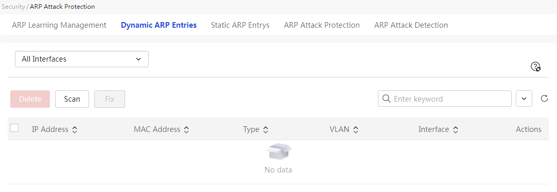
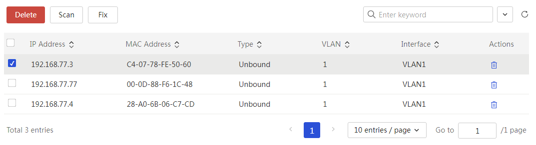
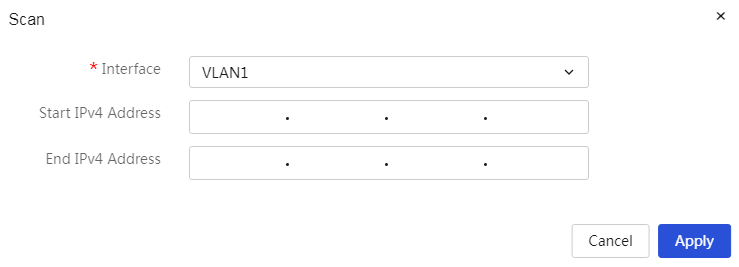
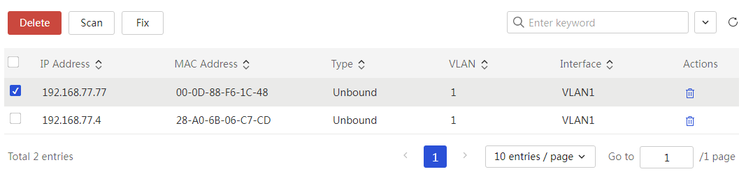
Parameters
Table 46 Parameter description
|
Parameter |
Description |
|
IP address |
The IP address in this dynamic ARP information |
|
MAC |
The MAC address in this dynamic ARP information |
|
Type |
The type of this dynamic ARP information, mainly divided into: · Unbound: Indicates that this entry is a dynamically learned ARP entry · Dynamic binding: Indicates that this entry was automatically bound while providing ARP protection for a DHCP-assigned address |
|
VLAN |
The VLAN to which this dynamic ARP information belongs |
|
Ports |
The interface to which this dynamic ARP information belongs |
|
Task |
This dynamic ARP information can be edited |
Static ARP management
About this task
This function includes static ARP entry management, refreshing, adding, and importing/exporting functions. The refresh function refers to refreshing the static ARP entry list; the add function refers to manually adding static ARP entries; the import function refers to batch obtaining static ARP entries from files; the export function refers to exporting existing static ARP entries to a local file.
Procedure
Page wizard: [Network Security/ARP Security/Static ARP Management]
|
This page provides you with the following main functions: · Display static ARP information · Add static ARP entries · Delete static ARP entries · Import static ARP entries · Export static ARP entries · Modify ARP entries |
|
|
Add static ARP entries: 1. Click the <Add> button to open the Add ARP Entry dialog box, then enter the IP address and MAC address 2. Click Apply. |
|
|
Delete static ARP entries: 3. Select the static ARP entries you want to delete, then click the <Delete> button to open the confirmation prompt dialog box 4. Click Apply. |
|
|
Import static ARP entries: 1. Click the <Import> button to open the Import ARP Entry dialog box, then click the <Upload File> button to upload ARP entries 2. Click Apply. |
|
|
Modify ARP entries: 1. Click the edit icon in the operation column corresponding to the ARP entry you want to modify to open the Modify ARP Entry dialog box, then enter the configuration items you need to modify 2. Click Apply. |
|
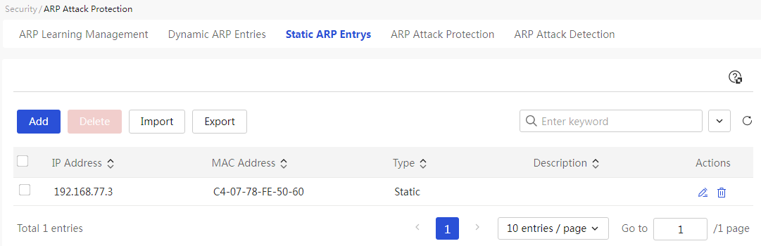
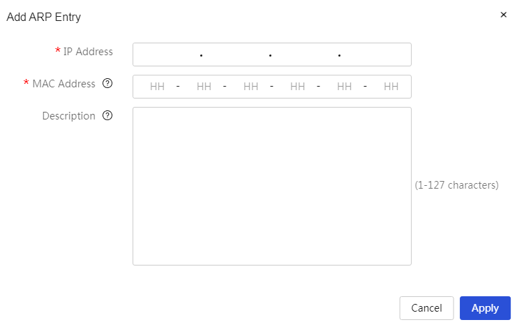
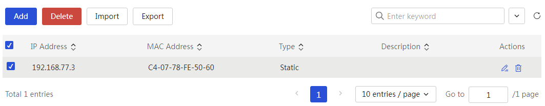
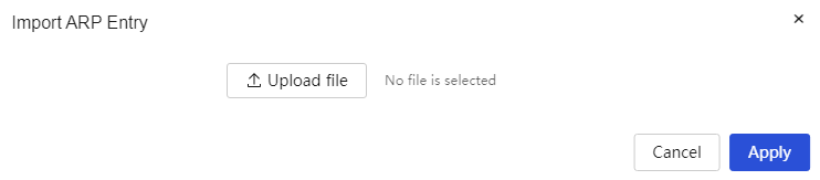
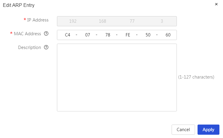
The meanings of each parameter on the page are shown in the following table.
Table 47 Parameter description
|
Item |
Description |
|
IP address |
The IP address in this static ARP information |
|
MAC |
The MAC address in this static ARP information. Full 0 or full F MAC addresses are not supported here. |
|
Type |
The type of this static ARP information, which is static, indicating that the device's IP address is bound to the MAC address, forming a static ARP entry. |
|
Description |
Description information for the ARP entry, allowing for a simple description of the entry for easier use. |
|
Task |
You can edit or delete this static ARP information. |
ARP protection
About this task
This includes ARP message validity checks and free ARP functions. ARP message validity checks are performed by setting rules to verify the validity of ARP messages. Free ARP messages are a special type of ARP message where both the sender's IP address and the target IP address are the local machine's IP address, with the source MAC address being the local machine's MAC address, and the destination MAC address being the broadcast address. The device sends free ARP messages to achieve the following functions:
· To determine whether the IP address of other devices conflicts with the local machine's IP address. When other devices receive the free ARP message and find that the IP address in the message is the same as their own, they will respond with an ARP reply to inform the device sending the free ARP message of the IP address conflict.
· If the device changes its hardware address, it sends free ARP messages to notify other devices to update their ARP entries.
Restriction and guidelinks
· Sending free ARP can prevent hosts on the LAN or WAN side from ARP attacks and spoofing. The smaller the time interval for sending free ARP is set, the stronger the host's ability to prevent ARP attacks, but the more network resources it consumes, so please set the free ARP message sending time interval reasonably.
· Since some devices (such as switches) may restrict ARP messages, excessive ARP messages may be deemed as an attack; please determine whether to enable the active sending of free ARP and make reasonable parameter settings.
· Routers support the timed sending of free ARP functions, allowing timely notifications to other devices to update ARP entries or MAC address entries to prevent spoofing gateway ARP attacks and prevent aging of host ARP entries, etc.
Procedure
Page wizard: [Network Security/ARP Security/ARP Protection]
|
1. Set ARP message validity check and free ARP 2. Click<Apply>button to complete the configuration |
|
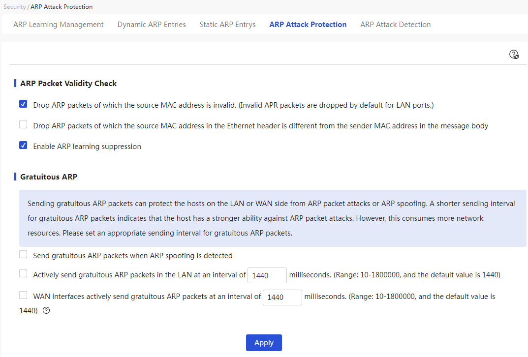
Parameters
Table 48 Parameter description
|
Parameter |
Description |
|
ARP Packet Validity Check |
ARP packet validity is verified by setting rules, mainly divided into: · Discard ARP packets with an invalid sender MAC address (the LAN port discards invalid ARP packets by default): When the source MAC address in the received ARP packet is all zeros, multicast, or a broadcast MAC address, the device will not learn this ARP packet and will discard it directly. · Discard ARP packets where the source MAC address in the packet header does not match the sender MAC address in the packet: When the source MAC address in the received ARP packet does not match the Layer 2 source MAC address of the packet, the device will not learn this ARP packet and will discard it directly. · ARP Packet Learning Suppression: When the device sends an ARP request packet and receives multiple different ARP response packets, the device will only learn the first ARP response packet received. |
|
Gratuitous ARP |
A special ARP packet that carries both the sender IP address and target IP address as the local IP address, with the source MAC address being the local MAC address and the destination MAC address being the broadcast address. It is mainly divided into: · Send Gratuitous ARP packet upon detecting ARP spoofing: When the device detects ARP spoofing (for example, when the source IP address is the device's interface IP address but the source MAC address is not the device's interface MAC address), it will actively send a Gratuitous ARP packet. · Active sending of Gratuitous ARP packets within the LAN: Additionally, input the sending interval for Gratuitous ARP packets in the "Sending Interval" configuration item. · Active sending of Gratuitous ARP packets on the WAN port: Additionally, input the sending interval for Gratuitous ARP packets in the "Sending Interval" configuration item. When the WAN port is connected to the internet via a static address/DHCP, it actively sends Gratuitous ARP packets; when connected via PPPoE, sending Gratuitous ARP packets is not supported. |
ARP detection
About this task
ARP detection: Probe all onlink devices under the specified interface and check whether their information conflicts with existing ARP entries. Based on the search results, ARP binding operations can be performed.
Procedure
Page wizard: [Network Security/ARP Security/ARP Detection]
|
1. Select the specified interface and enter the designated IP address range. 2. Click the <Scan> button to perform ARP detection. |
|
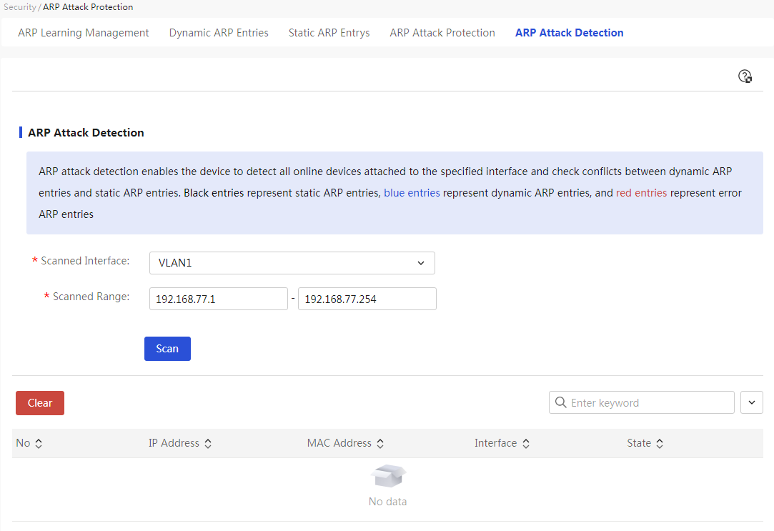
Parameters
Table 49 Parameter description
|
Parameter |
Description |
|
Scanning Interface |
Interface for the device to perform ARP detection |
|
Scanning Address Range |
Starting IP address and ending IP address for ARP detection Settings complete, click the “Scan” button to perform ARP detection |
|
No. |
Number of detected ARP entries |
|
IP address |
IP address in the ARP information |
|
MAC |
MAC address in the ARP information |
|
Ports |
Interface to which the ARP information belongs |
|
Status |
ARP detection result status, mainly divided into: · Static Entry: This entry is a black entry, indicating a manually configured or automatically bound ARP entry · Dynamic Entry: This entry is a blue entry, indicating a dynamically learned ARP entry that has not been automatically bound · Error Entry: This entry is a red entry, indicating the presence of an ARP conflict entry |
DDoS attack defense
Introduction
A DDoS attack is a widespread type of attack on the Internet that can cause greater harm than traditional denial of service (DoS) attacks. It allows devices to protect against common attack types from both external and internal networks, discarding attack packets. Meanwhile, the device can log corresponding attack events.
Attack defense
About this task
This function enables devices and networks to be protected from the following DDoS attacks:
· Single Packet Attack: The attacker uses malformed packets to launch an attack aimed at paralyzing the target system. For example, a Land attack packet is a TCP packet where both the source IP and destination IP are the target IP, which exhausts the connection resources of the target server, preventing it from handling normal business.
· Abnormal flow attack—Attackers send a large number of forged requests to the target system, causing the target system to be overwhelmed with useless information, thus unable to provide normal services to legitimate users.
· Scanning attack—Attackers scan host addresses and ports, probe the target network topology and open service ports to prepare for further intrusion into the target system.
Procedure
Page Wizard: [Network Security/DDoS Attack Defense/Attack Defense]
|
This page provides the following main functions: · Display the added DDOS attack defense strategies · Turn on or off DDOS attack defense · Add DDOS attack defense strategies · Delete DDOS attack defense strategies · Edit added DDOS attack defense strategies |
|
|
Add DDOS attack defense strategies: 1. Click<Add> button to pop up the new attack defense dialog box, select the application interface and attack defense type 2. Click Apply. |
|
|
Delete DDOS attack defense strategies: 1. Select the attack defense strategies to delete and then click<Delete> button to pop up the acknowledgment prompt dialog box 2. Click Apply. |
|
|
Edit added DDOS attack defense strategies: 1. Click the edit icon in the operation column corresponding to the attack defense that needs to be edited to pop up the edit attack defense dialog box, and modify the relevant configurations 2. Click Apply. |
|
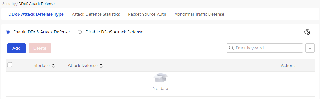
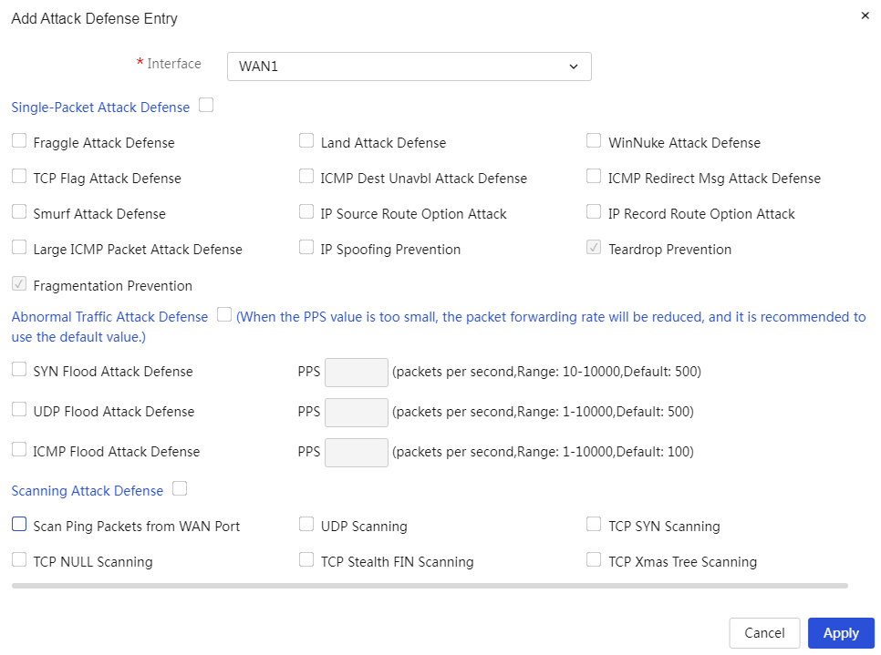
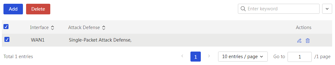
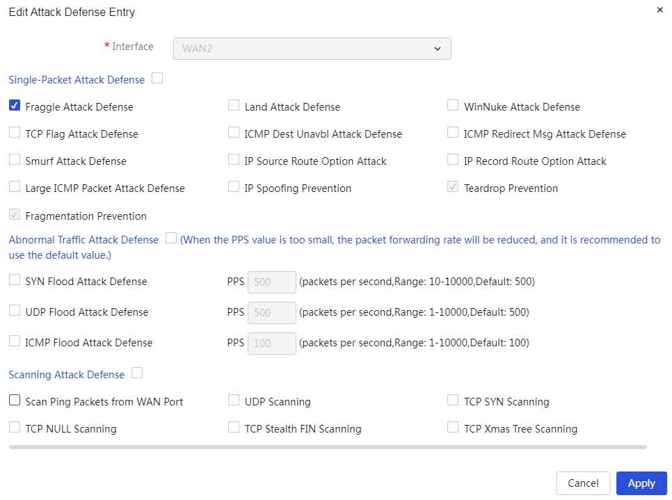
Parameters
Table 50 Parameter description
|
Parameter |
Description |
|
DDoS Attack Defense |
Enable this function to allow the device to defend against common DDoS attacks from both external and internal networks, discard attack packets, and log the corresponding attack events. |
|
Application Interface |
The source interface of the attack packets, meaning the rules apply DDoS attack defense to packets received from a specific interface. |
|
Attack defense |
Types of DDoS attack defense performed by the device, mainly divided into: · Single Packet Attack Defense: Defends against attackers using malformed packets to launch attacks that cripple the target system. This mainly includes: ¡ Fraggle Attack Defense: When enabled, the device can effectively prevent Fraggle attacks. This attack involves an attacker sending UDP packets with the source address of the victim network or host to the subnet broadcast address. Each host in the subnet responds to the victim network or host, leading to network congestion or host crashes. ¡ Land Attack Defense: When enabled, the device can effectively prevent Land attacks. This attack involves an attacker sending TCP packets with the SYN flag, where both the source and destination addresses are set to the target's IP address. When the target machine receives such packets, it begins an internal response storm, consuming a large amount of CPU resources. ¡ WinNuke Attack Defense: When enabled, the device can effectively prevent WinNuke attacks. This attack involves an attacker exploiting the OOB (Out of Band) vulnerability in the NetBIOS protocol to attack the target, potentially causing some hosts to crash or blue screen. ¡ TCP Flag Attack Defense: When enabled, the device can effectively prevent TCP flag attacks. This attack involves an attacker sending packets with unconventional TCP flags to probe the operating system type of the target host. If the operating system mishandles these packets, the attacker can cause the target host system to crash. ¡ ICMP Unreachable Packet Attack Defense: When enabled, the device can effectively prevent ICMP unreachable packet attacks. This attack involves an attacker sending ICMP unreachable packets to the target to sever the network connection of the target host. ¡ ICMP Redirect Packet Attack Defense: When enabled, the device can effectively prevent ICMP redirect packet attacks. This attack involves an attacker sending ICMP redirect packets to the target, altering the target's routing table and interfering with normal IP packet forwarding. ¡ Smurf Attack Defense: When enabled, the device can effectively prevent Smurf attacks. This attack is similar to the Fraggle attack, where an attacker broadcasts an ICMP echo request packet to a subnet with the source address of the attacked host. When all hosts in the subnet receive the echo request, they respond with ICMP echo reply packets to the attacked host, resulting in network congestion or system crashes for the attack target. ¡ IP Attack with Source Route Option Defense: When enabled, the device can effectively prevent IP attacks with source route options. This attack involves an attacker sending IP packets with source route options to the target to probe the network structure. ¡ IP Attack with Record Route Option Defense: When enabled, the device can effectively prevent IP attacks with record route options. This attack involves an attacker sending IP packets with record route options to the target to probe the network structure. ¡ Oversized ICMP Attack Defense: When enabled, the device can effectively prevent oversized ICMP attacks. This attack involves an attacker sending oversized ICMP packets to the target, causing the target host to crash. ¡ Prevent IP Spoofing: When enabled, the device can effectively prevent IP spoofing attacks. This attack involves an attacker using the same IP address to impersonate a legitimate host on the network and access critical information, typically masquerading as an IP address within the LAN. ¡ Prevent TearDrop: When enabled, the device can effectively prevent TearDrop attacks. This option is enabled by default and cannot be disabled. This attack involves an attacker sending overlapping fragmented packets to the target, which may cause the target host to crash when processing these fragments. ¡ Prevent Fragmented Packet Attacks: When enabled, the device can effectively prevent fragmented packet attacks. This option is enabled by default and cannot be disabled. This attack involves an attacker sending partial fragmented packets to the target host without sending all the fragments, causing the target host to wait indefinitely until the timer expires. If the attacker sends a large number of fragmented packets, it will exhaust the target host's resources, preventing it from responding to normal IP packets. · Anomaly Flow Attack Defense: Defends against attackers sending a large number of forged requests to the target system, leading the target system to become overwhelmed with useless information and unable to provide normal service to legitimate users. This mainly includes: ¡ SYN Flood Attack Defense: Select this option and set the threshold to enable SYN Flood attack prevention. When the traffic rate exceeds this threshold, the device will enable SYN Flood attack defense. This attack involves an attacker sending a large number of SYN packets to the target, consuming the target's connection resources and preventing the target system from accepting new connections. ¡ UDP Flood Attack Defense: Select this option and set the threshold to enable UDP Flood attack prevention. When the traffic rate exceeds this threshold, the device will enable UDP Flood attack defense. This attack involves an attacker sending a large number of UDP packets to the target, causing the target host to be busy processing these UDP packets and unable to continue processing normal packets. ¡ ICMP Flood Attack Defense: Select this option and set the threshold to enable ICMP Flood attack prevention. When the traffic rate exceeds this threshold, the device will enable ICMP Flood attack defense. This attack involves an attacker sending a large number of ICMP packets to the target, causing the target host to be busy processing these ICMP packets and unable to continue processing normal packets. · Scanning Attack Defense: Defends against attackers scanning host addresses and ports to probe the target network topology and open service ports, preparing for further intrusion into the target system. This mainly includes: ¡ WAN Port Ping Scan: When enabled, the device will not respond to Ping requests from the Internet, preventing malicious Ping probes from the Internet. ¡ UDP Scan: When enabled, the device can effectively prevent UDP scanning attacks. This attack involves an attacker sending UDP packets to the target port to probe the port's openness. ¡ TCP SYN Scan: When enabled, the device can effectively prevent TCP SYN scanning attacks. This attack involves an attacker sending SYN packets to the target port as if establishing a normal TCP connection, then waiting for the target host's response to probe the port's openness. ¡ TCP NULL Scan: When enabled, the device can effectively prevent TCP NULL scans. This attack involves an attacker sending TCP packets with no flags set to the target port, then waiting for the target host's response to probe the port's openness. ¡ TCP Stealth FIN Scan: When enabled, the device can effectively prevent TCP Stealth FIN scans. This attack involves an attacker sending TCP packets with only the FIN flag set to the target port, then waiting for the target host's response to probe the port's openness. ¡ TCP Xmas Tree Scan: When enabled, the device can effectively prevent TCP Xmas Tree scans. This attack involves an attacker sending TCP packets with FIN, URG, and PUSH flags set to the target port, then waiting for the target host's response to probe the port's openness. |
Attack defense statistics
About this task
This function can separately display statistical information on single packet attack defense and abnormal traffic attack defense, which can be exported to Excel for saving.
Procedure
Page Wizard: [Network Security/DDoS Attack Defense/Attack Defense Statistics]
|
View detailed information on "single package attack defense" and "anomaly attack defense," and support exporting this information in Excel format. |
|
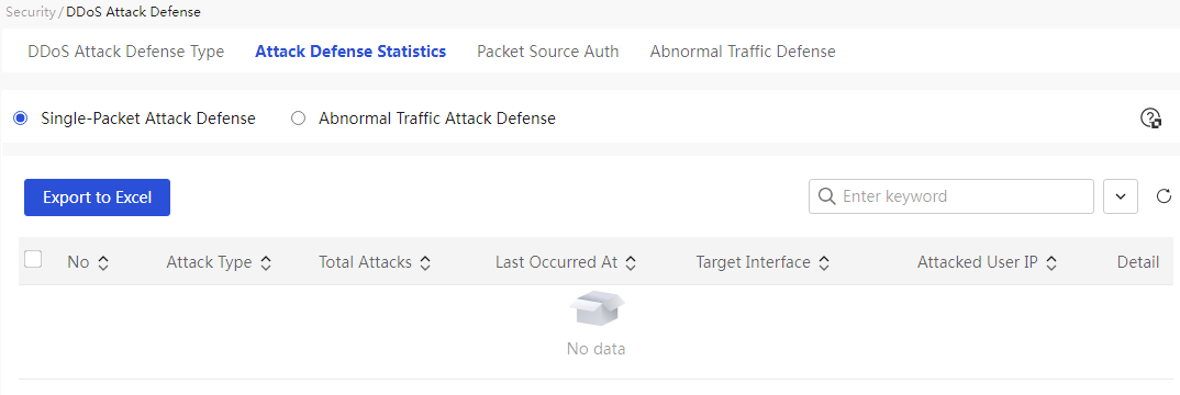
Parameters
Table 51 Page Parameter Description
|
Parameter |
Description |
|
No. |
Number of Attacks on Device |
|
Attack Type |
Type of Attack on Device. Includes specific attack types in single packet attack defense and abnormal traffic attack defense |
|
Total Count |
Total number of times the device has suffered such attacks. This parameter is displayed when viewing single packet attack defense statistics |
|
Last Occurrence Time |
Specific time when the device last suffered such an attack |
|
Attacked Interface/Attacked Security Zone |
Interface or security zone on the device that was attacked |
|
User IP Involved |
User IP address that launched the attack |
|
Detailed information |
Details of the attack, including: Serial Number, Attack Type, Source Address, Destination Address, Defense Action, Date, and Time |
Packet source authentication
About this task
This function refers to the device authenticating the source IP/MAC of received internal network packets to confirm whether the peer is a legitimate host, preventing potential illegal packet attacks within the internal network, avoiding consumption of device and network resources, and improving overall network stability.
Procedure
Page Wizard: [Network Security/DDoS Attack Defense/Packet Source Authentication]
|
1. Select message source authentication method 2. Click < application > button to complete configuration |
|
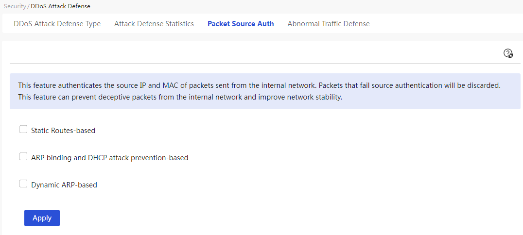
Parameters
Table 52 Parameter Description
|
Parameter |
Description |
|
Packet source authentication |
The device authenticates the source IP/MAC of the received internal network packets to acknowledge whether the other end is a legitimate host, preventing potential illegal packet attacks in the internal network, avoiding the consumption of device resources and network resources, and improving the overall stability of the network. This mainly includes: · Enabling source authentication function based on static route: After applying this, the device allows traffic from source IPs within the same subnet as the LAN interface or reachable internal routers through the static routing table with the outgoing interface as the LAN port. Other internal packets will be discarded by the device. · Enabling source authentication function based on ARP binding and DHCP attack protection: After applying this, the device will authenticate the packets coming from the internal network based on the static binding relationships in the ARP binding table and the corresponding relationships in the DHCP allocation list. If there is a conflict between the source IP/MAC of the packet and the IP/MAC correspondence in the ARP binding table, the packet will be discarded by the device. · Enabling source authentication function based on dynamic ARP: After applying this, the device will intelligently authenticate the source IP/MAC of internal packets to confirm whether the other end is a legitimate host. If the source IP/MAC of the packet conflicts with the IP/MAC of an already confirmed legitimate host, the packet will be discarded by the device. If there are applications in the network with the same MAC corresponding to different IPs, please perform static ARP binding for the corresponding IP/MAC; otherwise, it may affect normal business access. |
Abnormal traffic defense
About this task
This function refers to controlling hosts with abnormally high traffic within the internal network to prevent these abnormal hosts from excessively consuming bandwidth and system performance. There are three levels of protection, and you can select a suitable level based on your actual network conditions. To prevent illegally spoofed packet traffic from being counted among legitimate host traffic, it is recommended to enable relevant authentication features on the packet source authentication page as much as possible.
Procedure
Page Wizard: [Network Security/DDoS Attack Defense/Abnormal Traffic Protection]
|
Configure abnormal traffic protection. |
|
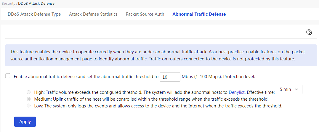
Parameters
Table 53 Parameter description
|
Parameter |
Description |
|
Abnormal traffic defense |
Control the abnormal high traffic from internal network hosts to prevent excessive consumption of device bandwidth and processing performance. The IP rating is mainly divided into: · High: The highest level of protection. Under high protection, the device will detect abnormal host traffic and automatically add detected attacking hosts to the denylist. During the specified time-range (TRANGE), it will prohibit access to this device and the Internet to minimize the impact of the abnormal host on the network. · Medium: A moderate level of protection. Under medium protection, the device will limit the upstream traffic of a single internal network host to within the abnormal traffic threshold range. Any traffic exceeding the threshold will be discarded by the device. · Low: A low level of protection. Under low protection, the device will only log abnormal traffic and still allow the corresponding host to access the device and the Internet. |
|
Abnormal Traffic Threshold |
The maximum value of abnormal traffic; if it exceeds the set threshold, the device will take control measures for this abnormal traffic. |
IPv6 neighbor list
About this task
The IPv6 neighbor list is an important concept in IPv6 networks, used to track and manage information about neighboring devices in the IPv6 network. Each IPv6 device maintains a neighbor list that contains information about other directly connected IPv6 devices, such as MAC address, neighbor status, and reachability status. The neighbor list plays a significant role in IPv6 networks, helping devices perform packet forwarding, address resolution, and neighbor discovery, while also assisting in network management and troubleshooting.
Neighbor entries save information about the neighbors of a device within the same link. They can be dynamically generated through NS and NA messages or manually created.
Procedure
Page Wizard: [Network Security/IPv6 Neighbor List]
|
This page provides the following main functions: · Display created IPv6 neighbor entries · Add static IPv6 neighbors · Edit IPv6 neighbor entries · Delete IPv6 neighbor entries |
|
|
Add static IPv6 neighbor: 1. Click the <Add> button to pop up the add IPv6 neighbor dialog box, select the binding interface, and enter the IPv6 address and MAC address 2. Click the <OK> button to complete the addition |
|
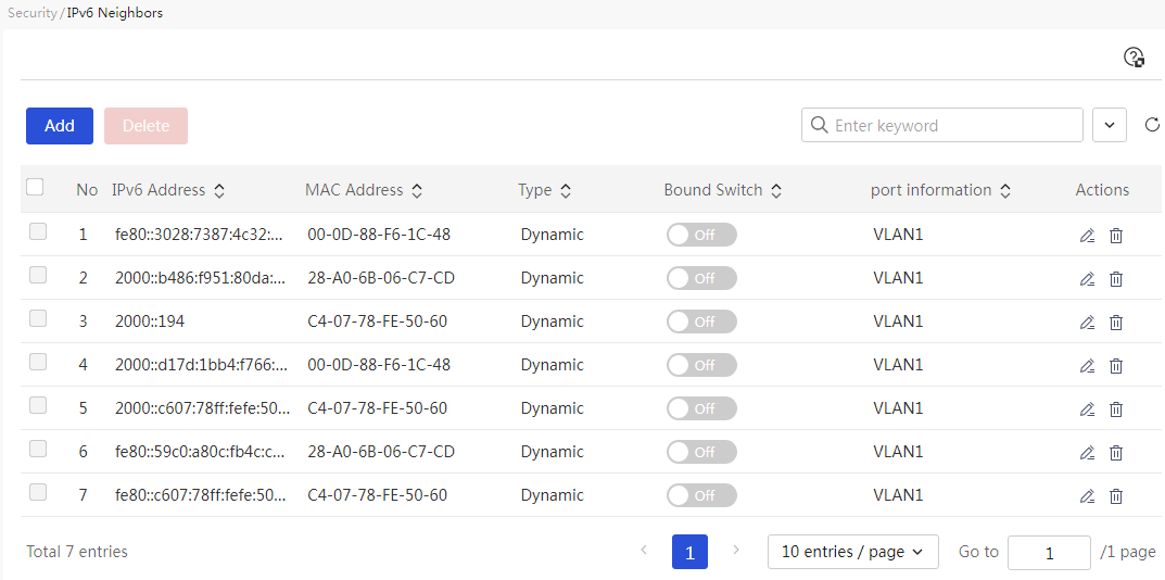
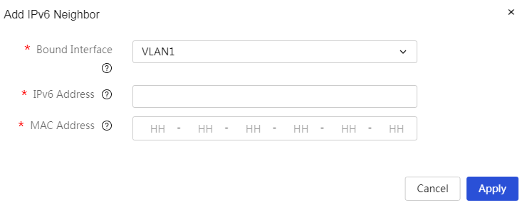
Parameters
Table 54 Parameter description
|
Item |
Description |
|
Bind an API to a proxy caching policy |
This node's Layer 3 interface, please select the VLAN set in the VLAN division. |
|
IPv6 address. |
The IPv6 address of the neighboring node connected to this node's Layer 3 interface. |
|
MAC |
The MAC address of the neighboring node connected to this node's Layer 3 interface. |
|
Binding switch |
For dynamically generated IPv6 neighbor entries, enabling the binding switch can convert them into static IPv6 neighbor entries. |
Denylist management
About this task
The denylist management feature is used to view and remove users that have been added to the denylist.
Procedure
Page Wizard: [Network Security/Denylist Management]
|
View the information of users added to the denylist and support removing them from the denylist. |
|
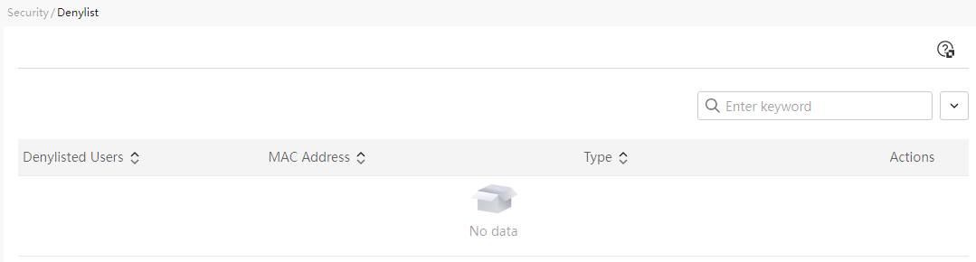
Parameters
Table 55 Parameter Description
|
Item |
Description |
|
Denylist user |
Denylist user's IP address |
|
MAC |
Denylist user's MAC address |
|
Type |
Denylist user types are mainly divided into: Static denylist: Users manually added to the denylist using the blacklist button in the corresponding operation column on the "System Monitoring > Traffic Ranking" page of the device's web navigation bar, categorized as "Static denylist" Dynamic denylist: When the abnormal host traffic protection function is enabled on the "Network Security > DDOS Attack Defense" page of the device's web navigation bar, and the "IP rating" is set to "High", any abnormal hosts added to the denylist management will occur when the device receives abnormal traffic exceeding the set threshold, categorized as "Dynamic denylist" |
|
Actions |
For handling operations on this denylist user, if this denylist user is a normal access user, the denylist can be lifted. |
Endpoint access control
About this task
The access control feature can simultaneously match the source MAC address and source IP address in data packets. Only the endpoints that have both the MAC address and IP address matched are allowed to access the external network.
Procedure
Page Wizard: [Network Security/Terminal Access Control]
|
Configure terminal access control |
|
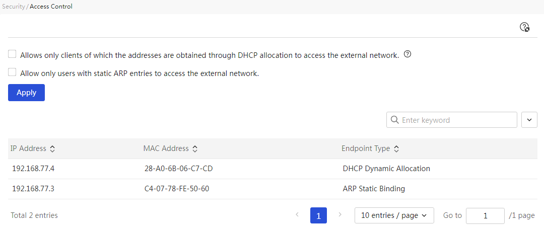
Parameters
Table 56 Parameter Description
|
Item |
Description |
|
Only clients assigned by the DHCP server are allowed to access the external network. |
If this function is enabled, users can specify that only clients assigned by the DHCP server can access the external network. After using this function, clients not in the customer list assigned by the DHCP Server will be unable to access the external network. After completing the settings, you need to click the <Apply> button to make the configuration effective. |
|
Only users with ARP static binding are allowed to access the external network. |
If this function is enabled, users can specify that only clients in the ARP static binding rule table can access the external network. After using this function, clients not in the ARP static binding rule table will be unable to access the external network. After completing the settings, you need to click the <Apply> button to make the configuration effective. |
|
IP address |
IP addresses controlled by the policy |
|
MAC |
MAC addresses controlled by the policy |
|
Endpoint Type |
User access control methods for the network are mainly divided into: · DHCP dynamic allocation: Indicates that clients dynamically assigned by the DHCP server are allowed to access the external network. · DHCP static allocation: Indicates that clients statically assigned by the DHCP server are allowed to access the external network. · ARP static binding: Indicates that clients in the ARP static binding rule table are allowed to access the external network. |
Virtual private networks
IPsec VPN
IPsec VPN is a virtual private network established using IPsec technology. IPsec protects the user data transmitted between specific communication parties by establishing a "channel," commonly referred to as an IPsec tunnel.
The IPsec protocol provides a complete security architecture for network data security at the IP layer, including security protocols AH (Authentication Header) and ESP (Encapsulating Security Payload), IKE (Internet Key Exchange), and various algorithms for network authentication and encryption. Among these, the AH and ESP protocols provide security services, while the IKE protocol is used for key exchange.
The device supports two networking methods for IPsec VPN:
· "Hub-and-Spoke" Networking: The branch gateway of an enterprise actively establishes an IPsec tunnel with the headquarters gateway, allowing internal terminals of the branch to securely access the headquarters' network resources.
· "Branch-to-Branch" Networking: Each branch gateway of the enterprise can actively establish IPsec tunnels with each other to protect data communications between branches.
Add an IPsec policy.
Page Wizard: Virtual Private Network (VPN)→IPsec VPN→IPsec Policy
|
This page provides you with the following main functions: · Display information about added IPsec policies · Add IPsec policies (including basic IPsec configuration, IKE configuration, and IPsec configuration) · Delete IPsec policy · Edit added IPsec policies |
|
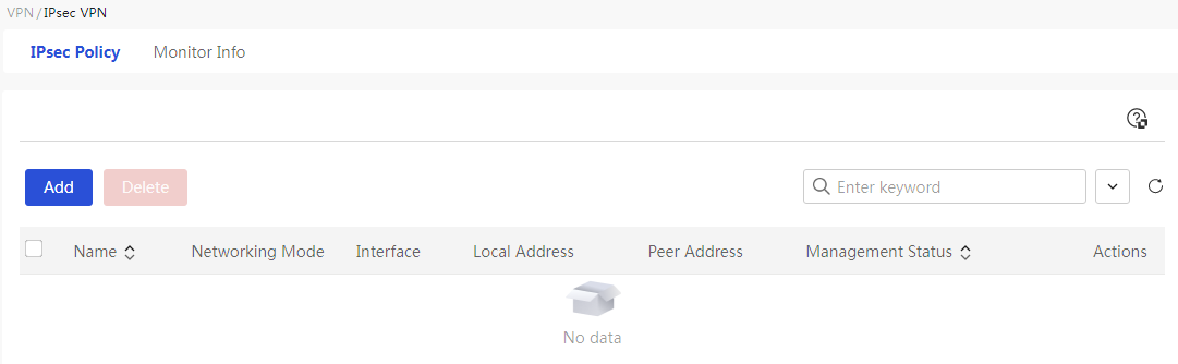
Add IPsec Policy (Basic Configuration)
|
|
IMPORTANT: · When the device acts as a central node, only one central node policy can be configured under a single interface. When adding an IPsec central node policy, select an interface that has not previously created a central node policy. · When adding protection flows, it is not recommended to configure multiple identical IP addresses with different masks simultaneously, for example, configuring both 192.168.1.1/24 and 192.168.1.1/16 protection flows at the same time. |
|
3. Click the <Add> button to open the Add IPsec Policy dialog box and configure the relevant parameters. 4. Click the <Show Advanced Configuration> button to complete the setup and proceed to the IKE configuration page. |
|
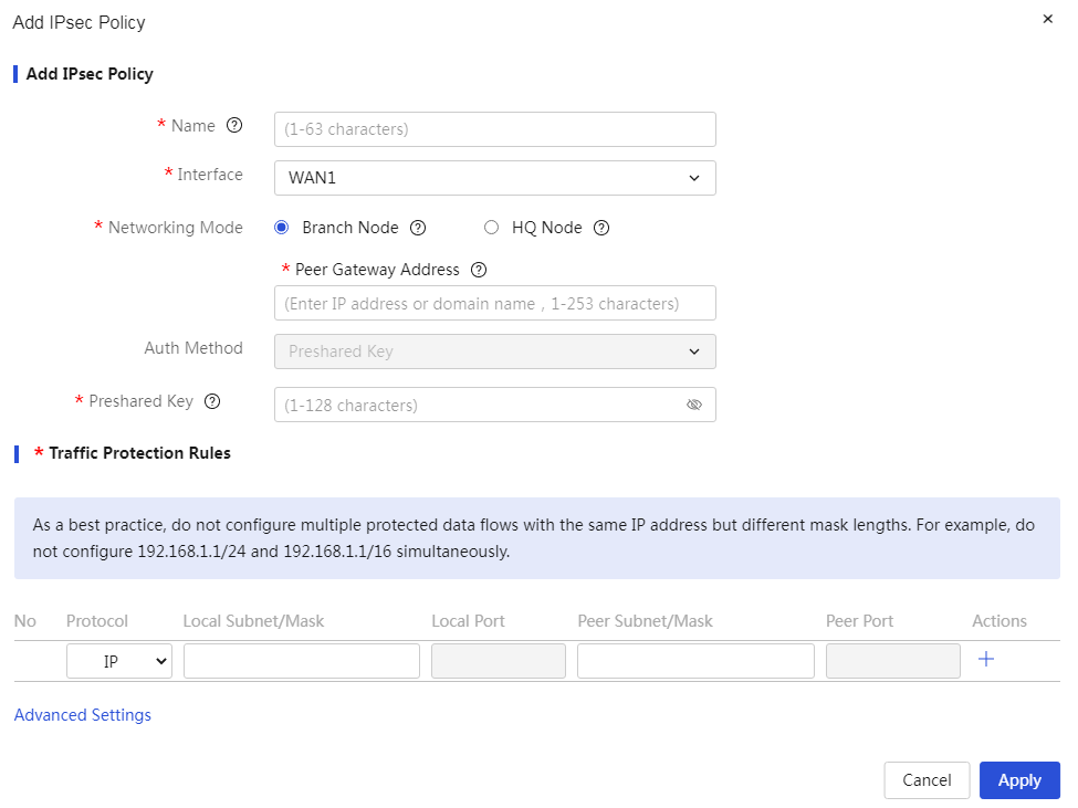
The meanings of the parameters on the page are shown in the table below.
Table 57 Parameter Description
|
Parameter |
Description |
|
Ports |
The source interface of the message, which controls the data packets received from a specific interface according to rules. When configuring this parameter, the interface must be routable to the peer device. |
|
Networking method |
There are two main ways to set up an IPsec VPN network: · Branch Node: The device acts as a branch node and establishes an IPsec tunnel with the central node. When configuring this parameter, you need to set the IP address or domain name of the IPsec tunnel's peer. This is usually the WAN address of the headquarters gateway or the peer branch gateway. · Central Node: The device acts as a central node and establishes an IPsec tunnel with branch nodes. |
|
Authentication |
Authentication method for the IPsec tunnel. This parameter currently only supports pre-shared key (PSK). |
|
Preshared Key |
Authentication password for the IPsec tunnel. When configuring this parameter, you need to enter the same pre-shared key as the peer device, which must be negotiated and announced in advance. |
|
No. |
Identifier for protected traffic. |
|
Protected Protocol |
The protocol type of the messages protected by the IPsec tunnel. It mainly includes: · If you need to control messages of a certain network layer protocol, select "IP," "IGMP," "GRE," "IPINIP," or "OSPF." · If you need to control messages of a certain transport layer protocol, select "TCP" or "UDP." · If you need to control ICMP protocol messages such as Ping or Tracert, select "ICMP." |
|
Protected Local Subnet/Mask |
Protected local subnet. For example, 1.1.1.1/24. |
|
Protected Local Port |
Protected local port. This parameter must be configured when the protected protocol is selected as TCP or UDP. |
|
Protected Peer Subnet/Mask |
Protected subnet of the peer node. For example, 2.2.2.2/24. |
|
Protected Peer Port |
Protected port of the peer node. This parameter must be configured when the protected protocol is selected as TCP or UDP. |
Add IPsec Policy (IKE Configuration)
|
1. Configure IKE-related parameters 2. Click the IPsec tab to enter the IPSec configuration page |
|
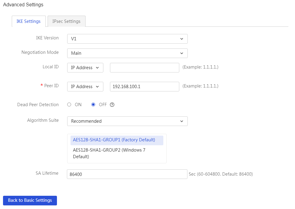
The meanings of the parameters on the page are shown in the table below.
Table 58 Parameter Description
|
Parameter |
Description |
|
IKE Version |
The version of the Internet Key Exchange protocol, mainly divided into: · If the IKE version used by the peer node is V1, then select "V1" on this end. · If the IKE version used by the peer node is V2, then select "V2" on this end. |
|
Negotiation Mode: |
The negotiation mode of the peers. Mainly divided into: · Main Mode: More negotiation steps, with identity verification occurring after the key exchange process, suitable for scenarios requiring high identity protection. · Aggressive Mode: Fewer negotiation steps, with identity verification occurring simultaneously with the key exchange, suitable for scenarios with low identity protection requirements. When the IKE version is V1, this parameter can be configured. If the device's public IP address is dynamically assigned, it is recommended to select Aggressive Mode for IKE negotiation. |
|
This End Identity Type |
The identity type and identity identifier of this end's device for IKE authentication. Mainly divided into: · If the peer node's IKE identity type is an IP address, then select "IP address" on this end. If the IKE negotiation mode is set to Main Mode, the identity type of this end's device needs to be configured as an IP address. The default is the device's outgoing interface IP address. · If the peer node's IKE identity type is FQDN, then select "FQDN," which is the FQDN name identifying this end's identity. · If the peer node's IKE identity type is User-FQDN, then select "User-FQDN," which is the User FQDN name identifying this end's identity. |
|
Peer Identity Type |
The identity type and identity identifier of the peer device for IKE authentication. Mainly divided into: · If the peer node's IKE identity type is an IP address, then select "IP address" on this end. If the IKE negotiation mode is set to Main Mode, the identity type of this end's device needs to be configured as an IP address. Generally, the device's outgoing interface IP address is used. · If the peer node's IKE identity type is FQDN, then select "FQDN," which is the FQDN name identifying this end's identity. · If the peer node's IKE identity type is User-FQDN, then select "User-FQDN," which is the User FQDN name identifying this end's identity. |
|
Dead Peer Detection (DPD) |
Whether to enable the Dead Peer Detection (DPD) function. If enabled, the device will check whether the tunnel peer is alive and remove the inactive IPsec tunnel. When configuring this parameter, the following must be set: · Probe Time: Every probe time interval, the device will perform a livelinkss check. The value ranges from 1 to 60, in seconds. · Timeout: If this time threshold is exceeded and the device cannot detect the peer, it is considered inactive. The value ranges from 2 to 300, in seconds. |
|
Algorithm Combination (IKE) |
The encryption and authentication algorithms required for IKE protocol interaction, which can be set in two ways: · Recommended: The algorithm combination recommended by the device. The recommended algorithm combinations configured at both ends of the IPsec tunnel must be consistent. · Custom: User-defined IKE algorithms, with options including: ¡ Authentication Algorithm: The authentication algorithm for IKE. The authentication algorithms configured at both ends of the IPsec tunnel must be consistent. ¡ Encryption Method: The encryption algorithm for IKE. The encryption algorithms configured at both ends of the IPsec tunnel must be consistent. ¡ PFS: Refers to the property that the compromise of one key does not affect the security of other keys. The PFS algorithms configured at both ends of the IPsec tunnel must be consistent. |
|
SA Lifetime |
The time interval for IKE renegotiation, which, if exceeded, will trigger the renegotiation of IKE-related parameters. It is recommended that the SA lifetime be set to no less than 600 seconds. |
Add IPsec Policy (IPsec Configuration)
|
Configure IPsec related parameters |
|
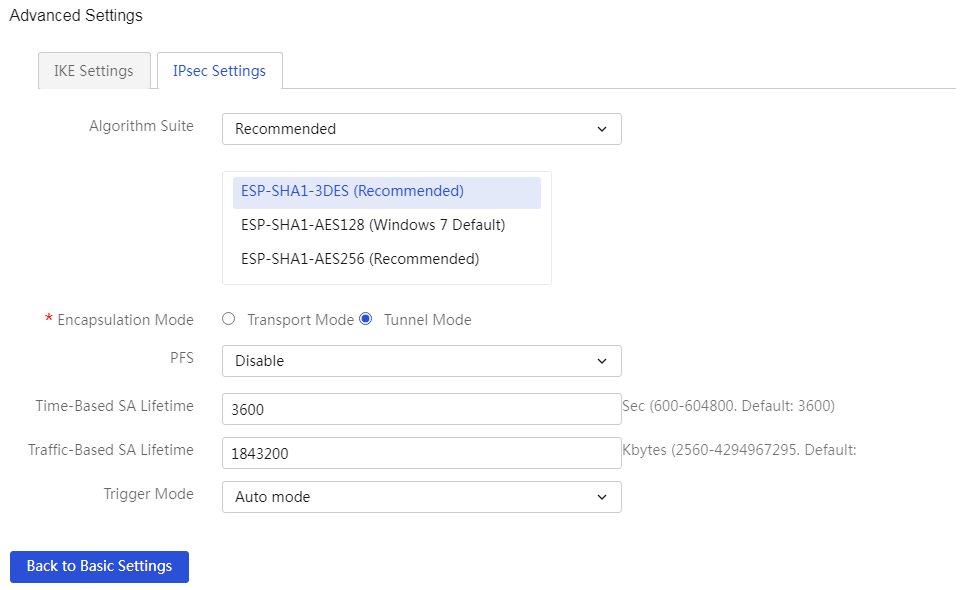
The meanings of the parameters on the page are shown in the table below.
Table 59 Parameter Description
|
Parameter |
Description |
|
Algorithm Combination (IPSEC Configuration) |
The encryption and authentication algorithms of the IPsec tunnel can be set in two ways: · Recommended: The algorithm combination recommended by the device. - The recommended algorithm combinations configured at both ends of the IPsec tunnel must be consistent. · Custom: User-defined IKE algorithms, mainly divided into: ¡ Security Protocol: Verifies the integrity of IP packets to determine whether the packets have been tampered with during transmission. The security protocols configured at both ends of the IPsec tunnel must be consistent. ¡ ESP Authentication Algorithm: The authentication algorithm for ESP. The ESP authentication algorithms configured at both ends of the IPsec tunnel must be consistent. ¡ ESP Encryption Algorithm: The encryption algorithm for ESP. The ESP encryption algorithms configured at both ends of the IPsec tunnel must be consistent. |
|
Encapsulation Mode |
The encapsulation modes of the IPsec tunnel are mainly divided into: · Transmission Mode: Suitable for establishing a tunnel between host and host. · Tunnel Mode: Suitable for establishing a tunnel between gateway and gateway. If both the protected network segment on this end and the protected network segment on the other end are private network segments, it is recommended to select the encapsulation mode as tunnel mode. The encapsulation modes configured at both ends of the IPsec tunnel must be consistent. |
|
PFS |
PFS Algorithm of the IPsec Tunnel. If this end is configured with PFS features, the negotiating peer must also be configured with PFS features, and the DH groups specified by this end and the peer must be consistent; otherwise, the negotiation will fail. |
|
Time-based SA Lifetime |
The time interval that triggers IPsec renegotiation, meaning exceeding the configured time will trigger the renegotiation of IPsec-related parameters. |
|
Traffic-based Lifetime |
The traffic size that triggers IPsec renegotiation, meaning exceeding the configured traffic will trigger the renegotiation of IPsec-related parameters. |
|
Trigger Mode |
The mode that triggers IPsec renegotiation is mainly divided into: · Traffic Trigger: After the IKE tunnel configuration is issued, the tunnel will not be established automatically and will wait for interest traffic to trigger the tunnel establishment. · Self-negotiation Mode: After the IKE tunnel configuration is issued or the tunnel is abnormally disconnected, it will automatically trigger tunnel establishment and ensure the tunnel is established for a long time without waiting for interest traffic to trigger. |
|
Admin Status |
Usage status of the IPsec policy is mainly divided into: · Enabled: Enable this policy. · Disabled: Disable this policy. |
|
Task |
This policy can be edited or deleted. |
Monitor Info
Page Wizard: Virtual Private Network (VPN)→IPsec VPN→Monitoring Information
|
Display the added IPsec policy information. |
|

The meanings of the parameters on the page are shown in the table below.
Table 60 Parameter Description
|
Parameter |
Description |
|
Policy name |
Name of the established IPsec tunneling policy |
|
Status |
Status of the established IPsec VPN tunnel. Only successfully established IPsec VPN tunnels with a status of UP are displayed |
|
Ports |
Source interface of the packet, meaning the rule controls the packets received from a specific interface |
|
Local address |
Local device's exit address |
|
Peer address |
Peer device's exit address |
|
IPsec proposal |
Algorithm information used by the IPsec VPN |
|
Task |
You can delete this tunnel information |
L2TP server
Perform this task to configure basic L2TP server parameters and enable L2TP.
To provide a secure, cost-effective solution for remote users (such as branches and travelers) of an enterprise to access resources in the internal network of the enterprise, configure the L2TP server.
An L2TP server is a device that can process PPP and L2TP protocol packets. Typically, an L2TP server is deployed on the border of the internal network of an enterprise.
Configuring L2TP
Page Wizard: Virtual Private Network (VPN)→L2TP Server→L2TP Configuration
|
This page provides you with the following main functions: · Enable and disable the L2TP server · Add L2TP group · Delete L2TP group · Edit added L2TP group |
|
|
Select the radio box for “Enable L2TP server”, then click the <OK> button to turn on the L2TP server. |
|
|
To add an L2TP group: 1. Click the <Add> button to open the new L2TP group page and configure the relevant parameters. 2. Click Apply. |
|
|
To delete an L2TP group: 1. Select the radio box for the L2TP group you want to delete, which will prompt a confirmation dialog box. 2. Click Apply. |
|
|
To edit an added L2TP group: 1. Click the edit icon in the corresponding action column of the L2TP group you wish to edit, which will open the modify L2TP group dialog box to change the relevant parameters. 2. Click Apply. |
|
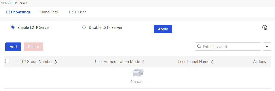
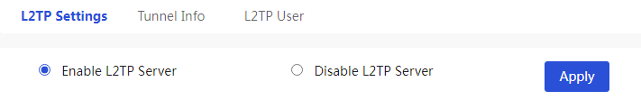
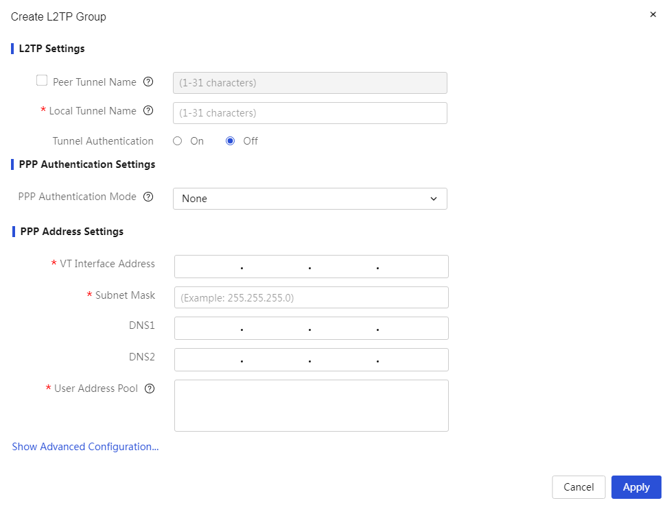
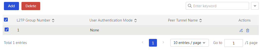

The meanings of the parameters on the page are shown in the table below.
Table 61 Parameter Description
|
Parameter |
Description |
|
Enable L2TP Server |
Whether to enable the L2TP server function. If this function is enabled, the device will provide a secure and economical way for remote users, such as those in overseas offices and business travelers, to communicate with the intranet and access network resources. The L2TP server function is disabled by default. |
|
Peer Tunnel Name |
L2TP Client Tunnel Name. You can choose whether to check this configuration item as needed. When configuring this parameter, enter the L2TP client tunnel name in the configuration item. The value can be 1 to 31 characters and does not support input of #, English semicolon, or spaces. |
|
This End Tunnel Name |
L2TP Server Tunnel Name. The value can be 1 to 31 characters and only supports letters [a-z, A-Z], digits, and underscores. |
|
Tunnel Authentication |
Whether to enable the L2TP tunnel authentication function. If this function is enabled, you need to enter the tunnel authentication password. This method is more secure, but requires both the L2TP server and L2TP client to enable tunnel authentication with the same password. The tunnel authentication password does not support input of #, English question mark, English semicolon, or spaces. |
|
PPP Authentication Method |
The authentication methods for L2TP users are mainly divided into: · None: No authentication for users. This method has the lowest security, please use it with caution. · PAP: Uses a two-way handshake mechanism for user authentication. This method has medium security. · CHAP: Uses a three-way handshake mechanism for user authentication. This method has the highest security. · MSCHAP: Uses symmetric cryptography to enhance security. · MSCHAPv2: An improved version of MS-CHAP, it uses a stronger hash algorithm and strengthens the encryption process. |
|
Username |
Username for Authentication. The value can be 1 to 55 characters and cannot include the English question mark (?). When the "PPP Authentication Method" selects PAP or CHAP, this parameter must be set. |
|
Password |
Password corresponding to the Username for Authentication. The value can be 1 to 63 characters. When the "PPP Authentication Method" selects PAP or CHAP, this parameter must be set. |
|
Virtual Template Interface Address |
The IP address of the virtual template interface, which allows the L2TP server to assign IP addresses to L2TP clients or users. |
|
Subnet mask |
Subnet Mask for Virtual Template Interface IP Address, for example, 255.255.255.0. |
|
DNS1 and DNS2 |
Primary and Secondary DNS assigned to L2TP clients or users. DNS1 and DNS2 cannot be the same. |
|
User Address Pool |
The address pool used to assign addresses to L2TP clients. The user address pool cannot contain the configured virtual template interface address. |
|
Hello Message Interval |
The time interval for sending Hello messages between the L2TP server and client. Hello messages are used to detect the connectivity of the tunnel between LAC and LNS, measured in seconds. |
Tunnel Information
Page Wizard: Virtual Private Network (VPN)→L2TP Server→Tunnel Information
|
Display L2TP tunnel information |
|
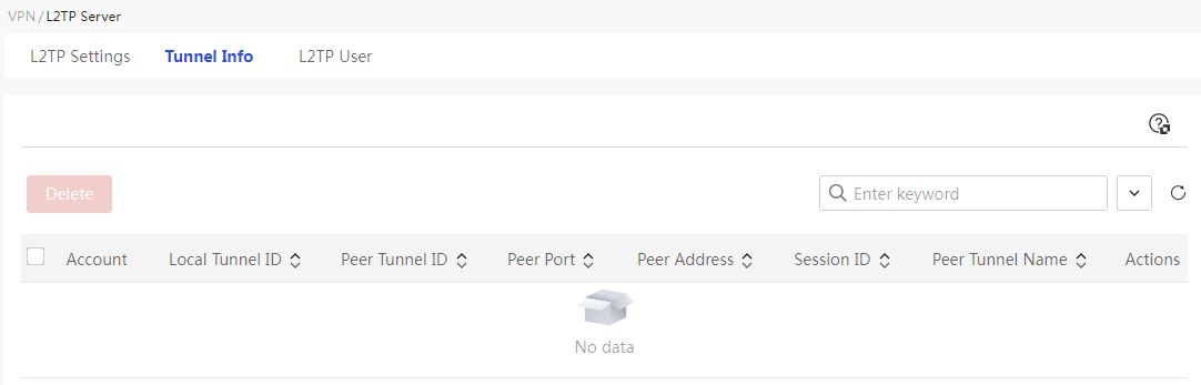
The meanings of the parameters on the page are shown in the table below.
Table 62 Page Parameter Description
|
Parameter |
Description |
|
Account Name |
L2TP Client Username |
|
Local Tunnel Number |
ID Number of Established Local Tunnel |
|
Peer Tunnel Number |
ID Number of Established Peer Tunnel |
|
Peer Tunnel Port |
Server Port Used for Connection Between L2TP Client and Server |
|
Peer Tunnel IP Address |
L2TP Client IP Address |
|
Number of Sessions |
Number of Sessions Established Between L2TP Server and Client |
|
Peer Tunnel Name |
L2TP Client Tunnel Name |
|
Task |
Can Perform Deletion Operation on Tunnel Information |
L2TP User
Page Wizard: Virtual Private Network (VPN)→L2TP Server→L2TP User
|
This page provides you with the following main functions: · Display the information of added L2TP users · Add a single L2TP user · Batch import L2TP users · Delete L2TP users · Export L2TP users |
|
|
Add a single L2TP user: 1. Click<Add> button to open the add user dialog box, then enter the relevant configuration items 2. Click<OK> button to complete the operation |
|
|
Batch import L2TP users: 1. Click<Import> button to open the L2TP user list dialog box 2. Click<Upload File> button to open the dialog box for selecting the file to load, then select the edited template 3. Click Apply. |
|
|
Export current L2TP users (Click<Export> button, the system will automatically export the current L2TP user list.) |
|
|
Delete L2TP user group: 1. Select the radio box in front of the L2TP users you want to delete 2. Click<Delete> button to open the confirmation prompt dialog box, then click<OK> button to complete the configuration |
|
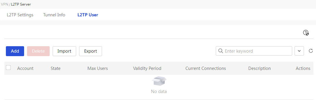
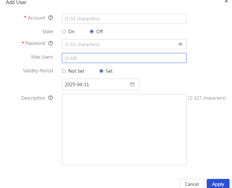
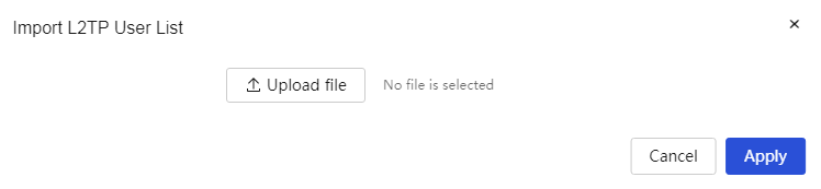
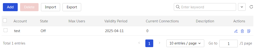
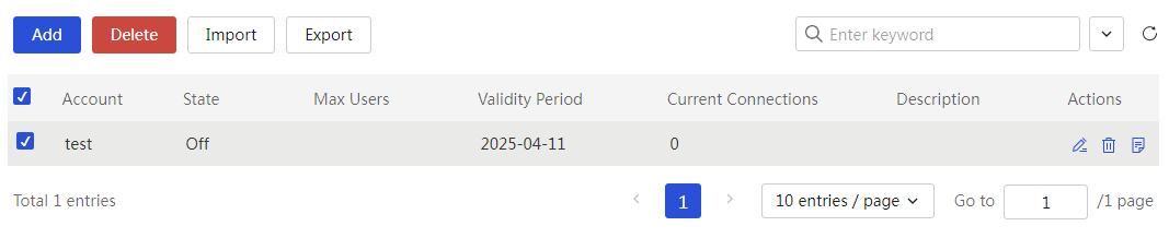
The meanings of the parameters on the page are shown in the table below.
Table 63 Parameter Description
|
Parameter |
Description |
|
Account Name |
Username for the L2TP client. The value must be between 1 and 55 characters, supporting only letters [a-z, A-Z], digits, and underscores. |
|
Status |
Status of the L2TP client. Mainly divided into: · Available: Allows the L2TP client to establish a session using this user. · Disabled: Prohibits the L2TP client from establishing a session using this user. |
|
Password |
Account password for the L2TP client. |
|
Maximum Number of Users |
Maximum number of L2TP clients allowed to connect to the intranet. |
|
Validity Period |
Expiration date for L2TP client authority. Mainly divided into: · Configure: You need to select the expiration date for user authority in the date selection box. · Not Configured: User authority remains valid indefinitely. |
|
Current Connection Count |
Number of L2TP clients onlink. |
|
Description |
Description information for the rule, providing a simple description for ease of use. |
|
Task |
This configuration can be edited and deleted. |
L2TP client
Perform this task to configure basic L2TP client parameters and enable L2TP.
If you want to provide a secure and cost-effective way for your enterprise's remote offices to communicate with the internal network and access internal network resources, you can achieve this by configuring the L2TP client.
An L2TP client is a device that can process PPP and L2TP protocol packets. Typically, an L2TP client is deployed on the egress of an enterprise branch.
Configuring L2TP
Page Wizard: Virtual Private Network (VPN)→L2TP Client→L2TP Configuration
|
This page provides you with the following main functions: · Enable and disable the L2TP client · Add L2TP groups · Delete L2TP groups · Edit added L2TP groups |
|
|
Select the radio box for "Enable L2TP Client," then click the <Acknowledge> button to start the L2TP client. |
|
|
Add L2TP group: 1. Click the <Add> button to pop up the new L2TP group page and configure the relevant parameters. 2. Click Apply. |
|
|
Delete L2TP group: 1. Select the radio box for the L2TP group you want to delete, which will pop up a confirmation dialog box. 2. Click Apply. |
|
|
Edit added L2TP group: 1. Click the edit icon in the operation column corresponding to the L2TP group you want to edit, which will pop up the modify L2TP group dialog box to change the relevant parameters. 2. Click Apply. |
|
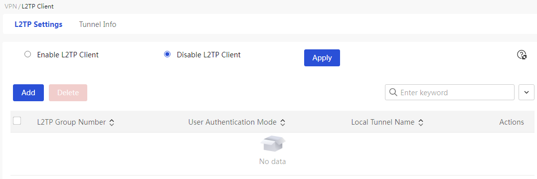


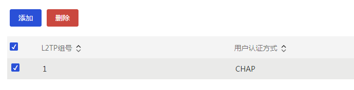
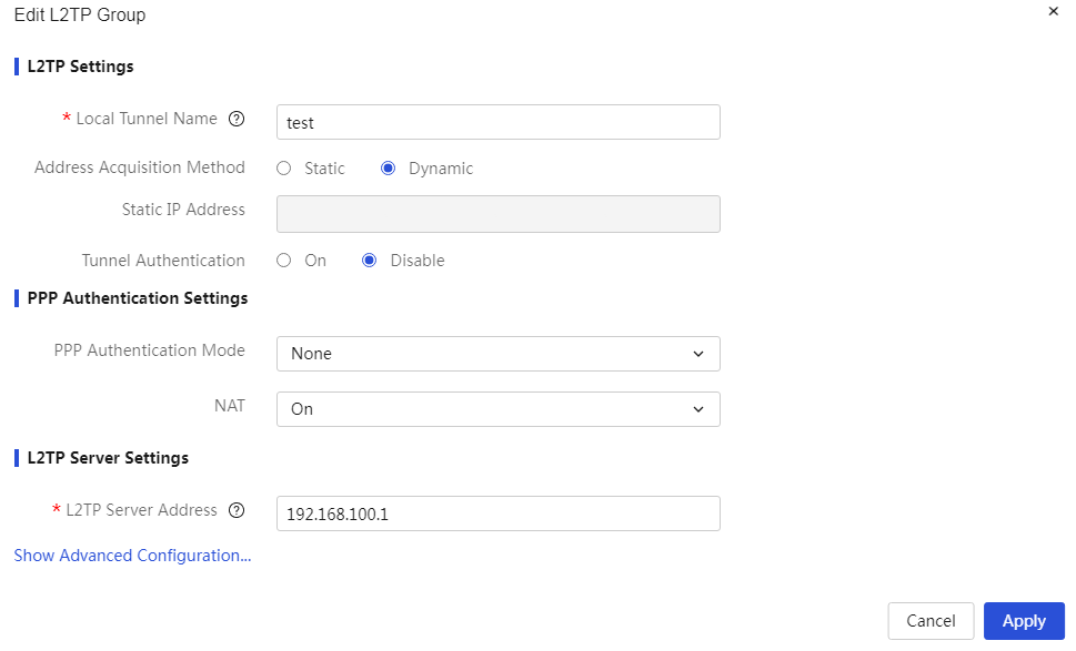
The meanings of the parameters on the page are shown in the table below.
Table 64 Page Parameter Description
|
Parameter |
Description |
|
L2TP Group Number |
Identifier for L2TP client rules |
|
L2TP Client |
Enable L2TP client function. If enabled, the device will access the intranet as an L2TP client. |
|
This End Tunnel Name |
Tunnel name for the L2TP client. The value can be 1 to 31 characters, supporting only letters [a-z,A-Z], digits, and underscores. |
|
IP Acquisition |
IP Address Acquisition Method for PPP Interface After L2TP Tunnel Establishment, mainly divided into: · Static: The L2TP client manually sets an IP (assigned by the L2TP server administrator). · Dynamic: The L2TP server dynamically assigns an IP address for the virtual PPP interface. The default is dynamic acquisition. |
|
Tunnel Verification |
Enable L2TP tunnel verification function. If enabled, a tunnel verification password must be entered. This method is more secure but requires both the L2TP server and client to enable tunnel verification and have matching passwords. The tunnel verification password does not support the input of #, question mark, semicolon, and spaces. |
|
PPP Authentication Method |
Authentication method for L2TP users, mainly divided into: · None: No authentication for users. This method has the lowest security; please use it cautiously. · PAP: Uses a two-way handshake mechanism for user authentication. This method has medium security. · CHAP: Uses a three-way handshake mechanism for user authentication. This method has the highest security. · MSCHAP: Uses symmetric cryptography to enhance security. · MSCHAPv2: An improved version of MS-CHAP, using a stronger hash algorithm and enhancing the encryption process. |
|
Username |
Username used for authentication. The value can be 1 to 55 characters and cannot include a question mark (?). This parameter must be set when "PPP Authentication Method" is selected as PAP or CHAP. |
|
Password |
Password corresponding to the authentication username. The value can be 1 to 63 characters. This parameter must be set when "PPP Authentication Method" is selected as PAP or CHAP. |
|
NAT Address Translation |
Address translation function; you can choose whether to enable this function based on actual needs when configuring this parameter. · If this function is enabled, the L2TP server does not need to configure routes to reach the client. · If this function is not enabled, the L2TP server must configure routes to reach the client for the L2TP client to access server resources properly. |
|
L2TP Server Address |
IP address or domain name of the L2TP server |
|
Hello Message Interval |
Time interval between sending Hello messages between the L2TP server and client. Hello messages are used to check the connectivity of the tunnel between LAC and LNS, measured in seconds. |
|
Task |
You can edit and delete this tunnel information. |
Tunnel information
Page Wizard: Virtual Private Network (VPN)→L2TP Client→L2TP Configuration
|
Display L2TP tunnel information |
|
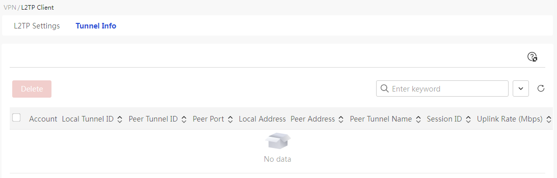
The meanings of the parameters on the page are shown in the table below.
Table 65 Parameter Description
|
Parameter |
Description |
|
Account Name |
L2TP Client Username |
|
Local Tunnel Number |
ID Number of Established Local Tunnel |
|
Remote Tunnel Number |
ID Number of Established Remote Tunnel |
|
Remote Tunnel Port |
Server Port Used to Establish Connection Between L2TP Client and Server |
|
Local address |
L2TP Client IP Address |
|
Remote Tunnel IP Address |
L2TP Server IP Address |
|
Peer Tunnel Name |
L2TP Server Tunnel Name |
|
Number of Sessions |
Number of Sessions Established Between L2TP Server and Client |
|
Upstream Speed (Mbps) |
Upstream Traffic Rate for L2TP Client Accessing Intranet |
|
Downstream Speed (Mbps) |
Downstream Traffic Rate for L2TP Client Accessing Intranet |
|
Task |
Can Perform Deletion Operation on This Tunnel Information |
Configure advanced settings
Manage application services
Application services provide DNS configuration functionality. DNS (Domain Name System) is a distributed database used for TCP/IP applications, providing a conversion between domain names and IP addresses. It mainly includes: static DNS, dynamic DNS, local domain services, and terminal automatic access to web services.
The setting rules for "Domain Name," "Local Domain Address," "Server Address," and "Terminal Automatic Access Address" are as follows:
· "Domain Name" and "Server Address" must be 1-253 characters; "Local Domain Address" must be 1-250 characters; "Terminal Automatic Access Address" must be 1-127 characters.
· A domain, server address, or local domain name can contain only letters, digits, hyphens (-), and dots (.)
· A domain, server address, or local domain name cannot start with or end with a dot (.) or hyphen (-), and cannot contain two or more consecutive dots (.) or hyphens (-).
· "Domain Name," "Local Domain Address," and "Server Address" must contain the symbol '.', and the characters after the last '.' cannot be all digits.
· "Terminal Automatic Access Address" does not support Chinese characters and spaces.
Configure static DNS
About this task
Static DNS is the manual establishment of a correspondence between domain names and IP addresses. When you access services provided by the device (such as Web, Mail, or FTP) using the domain name, the system will look up the static DNS resolution table to obtain the IP address corresponding to the specified domain name.
Procedure
Page Wizard: [Advanced Options/Application Services/Static DNS]
|
This page provides you with the following main functions: · Display details of added static DNS · Add static DNS · Delete added static DNS · Modify added static DNS |
|
|
Add static DNS: 1. Click the add button to pop up the new static DNS dialog box, and enter the domain name and IP address of the network device 2. Click Apply. |
|
|
Delete static DNS: 1. Select the static DNS you want to delete 2. Click the delete button to pop up a confirmation dialog box 3. Click Apply. |
|
|
Modify static DNS: 1. Click the edit icon in the operation column of the static DNS you want to modify, which will pop up the modify static DNS dialog box to change the relevant parameters 2. Click Apply. |
|

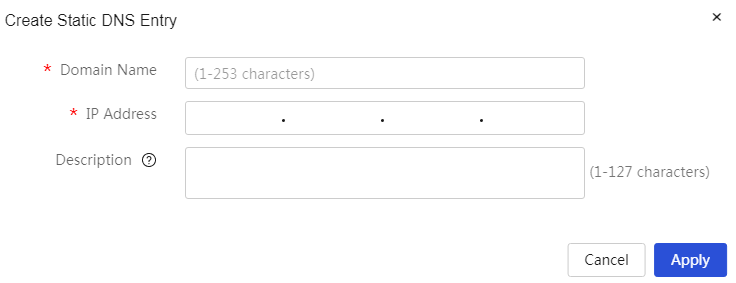
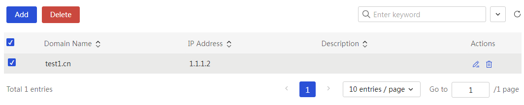
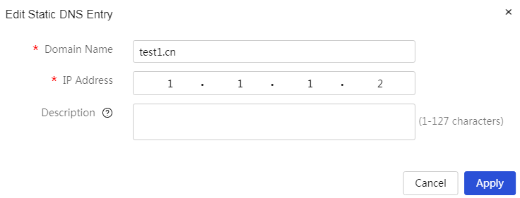
Parameters
Table 66 Parameter Description
|
Parameter |
Description |
|
Domain name. |
The domain name assigned to the device. When configuring this parameter, the domain name must correspond one-to-one with the device's IP address. |
|
IP address |
The device's IP address, which corresponds to the domain name. |
|
Description |
Description information for the rule, allowing for a simple description of the rule for easier use. |
|
Task |
You can edit and delete this configuration. |
Configure DDNS
About this task
Perform this task to configure DDNS for users to access services (such as Web, mail, or FTP) provided by a device's WAN interface through a fixed domain name when the WAN interface IP changes. For example, the WAN interface IP might change because of broadband dial-up.
Before using the DDNS service, you need to register an account and set a password in advance on the DDNS server (i.e., DDNS service provider, such as the Peanut Shell website). After that, when the WAN interface IP address of the device changes, the device will automatically notify the DDNS server to update the record of the IP address and the fixed domain name mapping.
Restriction and guidelinks
For the router to apply for a domain name from the DDNS server, make sure the IP address of the WAN interface is a public IP address.
Procedure
Page Wizard: [Advanced Options/Application Services/Dynamic DNS]
|
This page provides you with the following main functions: · Display details of added dynamic DNS · Add dynamic DNS · Delete added dynamic DNS · Modify added dynamic DNS |
|
|
Add dynamic DNS: 1. Click the add button to open the new dynamic DNS policy dialog box, select the WAN interface that provides the corresponding service on the device, and enter the domain name, username, and password registered with the provider. 2. Click Apply. |
|
|
Delete dynamic DNS: 1. Select the dynamic DNS you want to delete 2. Click the delete button to open a confirmation dialog box. 3. Click Apply. |
|
|
Modify dynamic DNS: 1. Click the edit icon in the action column of the dynamic DNS you want to modify to open the modify dynamic DNS policy dialog box and change the relevant parameters. 2. Click Apply. |
|
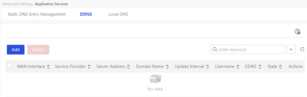
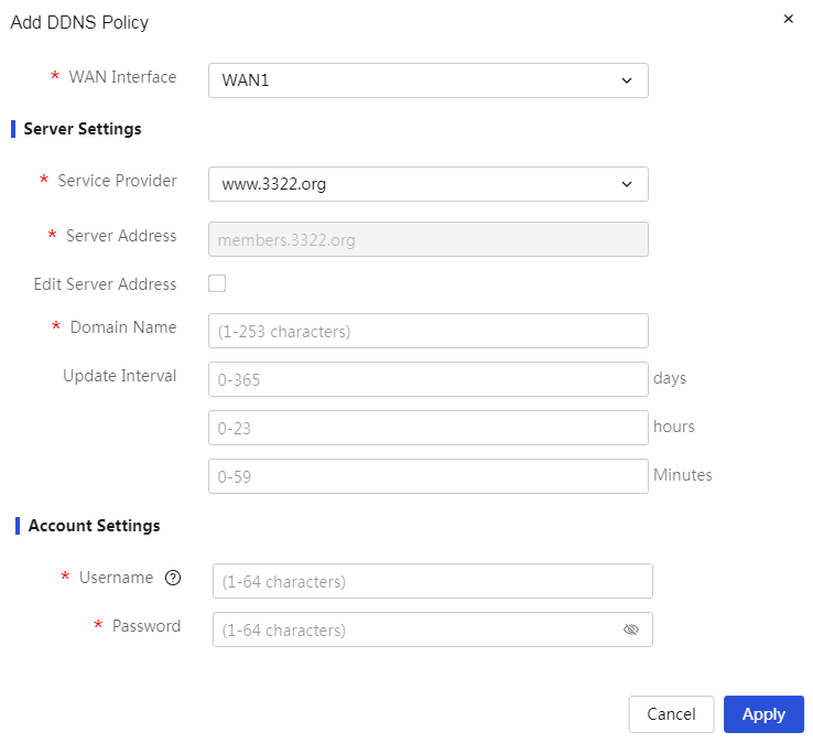
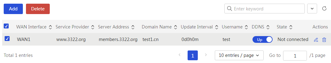
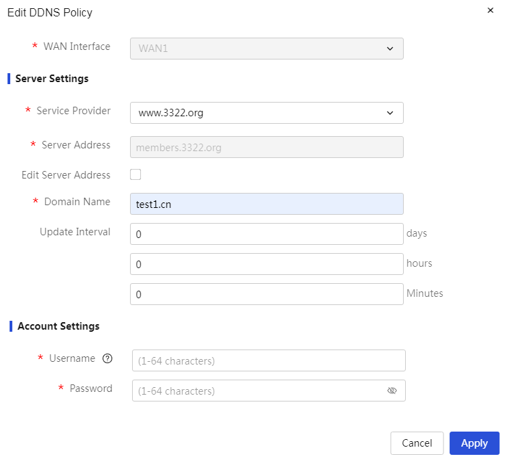
Parameters
Table 67 Parameter Description
|
Parameter |
Description |
|
WAN ports |
WAN interface on the device that provides services, such as WAN1 port |
|
Domain name. |
Domain name assigned to the device. When configuring this parameter, you need to register in advance with the DDNS server (i.e., DDNS provider) |
|
Service Provider |
Dynamic DNS service provider. If the server address differs from the default, select “Modify Server Address” and update the DDNS server address in the “Server Address” configuration item |
|
Update Interval |
Time interval at which the device sends update requests to the server. When configuring this parameter, specify days, hours, and minutes. If the configured time interval is 0, the device will only send update requests when the WAN interface IP address changes or the interface connection changes from down to up |
|
Account Configuration |
Account information for Dynamic DNS. Mainly includes: · Username: The username registered with the dynamic DNS provider · Password: The password registered with the dynamic DNS provider |
|
DDNS Function |
Whether to enable the DDNS function. If this function is enabled, the device will operate according to the configured DDNS policies and rules. The DDNS function is enabled by default |
|
Status |
Connection status of Dynamic DNS, mainly divided into: · Connected: This WAN interface has established a dynamic DNS connection with the domain name · Not Connected: This WAN interface has not established a dynamic DNS connection with the domain name |
|
Task |
You can edit and delete this configuration |
Configure the local DNS service
About this task
Endpoints in the internal network can access the Web management interface of the device by using the local domain name.
Restriction and guidelinks
Make sure the local domain name does not conflict with registered domain names in the Internet.
Procedure
Page Wizard: [Advanced Options/Application Services/Local Domain Services]
|
Set up local domain name service: 1. Enable local domain name service function 2. Set local domain address 3. Click<Apply>button to complete the configuration |
|
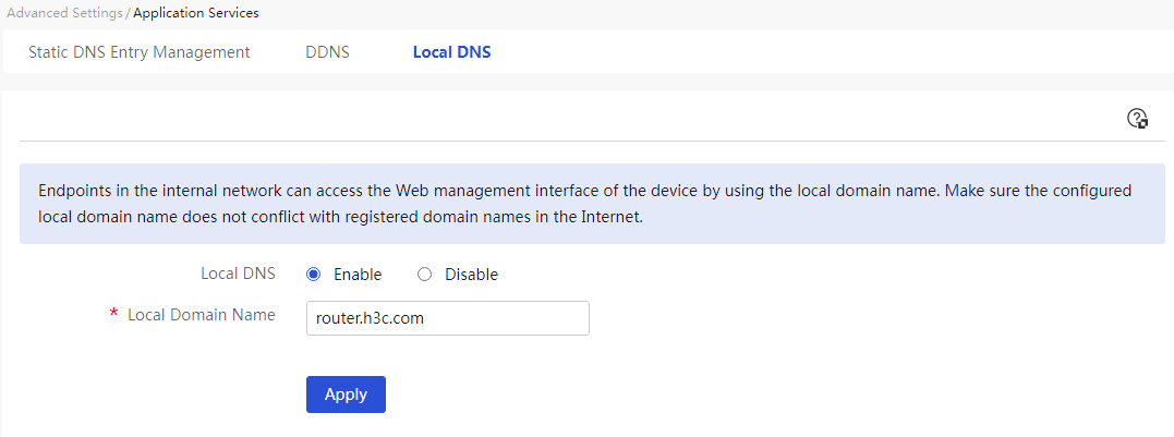
Parameters
Table 68 Page Parameter Item Descriptions
|
Parameter |
Description |
|
Local Domain Service |
Select whether to enable the local domain service. The default is enabled. |
|
Local Domain Address |
The domain name used by internal terminals to access the device's web management page. |
Static routes
About this task
Static routing is the process of manually setting fixed routing entries in the router. When your network structure is relatively simple and stable, configuring static routing can achieve network intercommunication. For example, when you know the outgoing interface of the network and the IP address of the gateway, setting static routing can enable normal communication.
When multiple static routes exist to the same destination, if you want to give priority to a specific static route, you can adjust the priority of the static route. The smaller the value of the priority, the higher the priority of the corresponding static route.
Restriction and guidelinks
When the interface corresponding to the next hop in the static route fails, the local static route entry will not be deleted. In this case, you need to check the network environment and then modify the static route configuration.
Procedure
Page Wizard: [Advanced Options/Static Routing]
|
This page provides you with the following main functions: · Display details of added static routes · Add static routes · Delete added static routes · Modify added static routes · View routing information table |
|
|
Add static route: 1. Click<Add> button to pop up the Add IPv4 Static Route dialog box, and enter the destination IP address, mask length, next hop, and other information 2. Click Apply. |
|
|
Delete static route: 1. Select the static route entries to be deleted 2. Click<Delete> button to pop up the confirmation dialog box 3. Click Apply. |
|
|
Modify static route: 1. Click the edit icon in the operation column of the static route to be modified, which will pop up the Modify IPv4 Static Route dialog box, and modify the relevant parameters 2. Click Apply. |
|
|
View routing information table: Click<View Routing Information Table> button to view the routing information table |
|
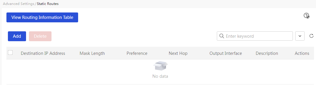
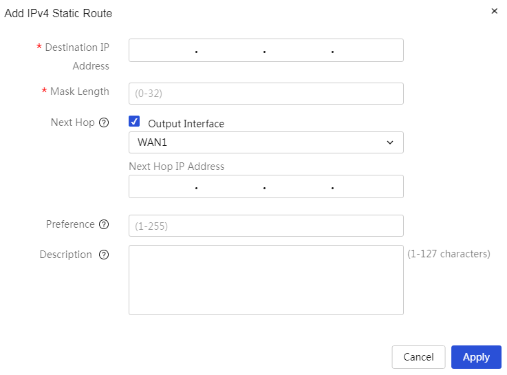
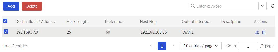
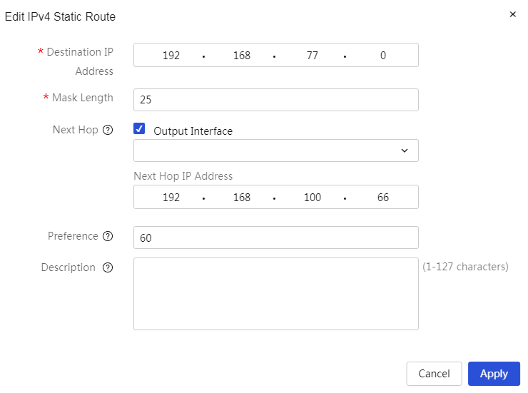

Parameters
Table 69 Parameter Description
|
Parameter |
Description |
|
Destination IP Address |
IP address of the destination network that the device needs to access |
|
Address Mask |
Mask length of the destination network, for example, 24 |
|
Next hop |
The IP address of the next router that the data needs to pass through before reaching the destination address. When configuring this parameter, you can select whether to check the "out interface" option as needed · If you are certain about the device exit that the data will go through, check the "out interface" option and set the next-hop IP address; the next-hop address must be in the same subnet as the selected interface · If you are unsure about the exit interface, do not check the "out interface" option. By setting the next-hop IP address, the device can choose an appropriate exit interface by itself |
|
Priority |
Precedence of the static route; when configuring this parameter, a smaller value indicates a higher precedence |
|
Description |
Description information for the rule; you can provide a simple description of the rule for easier use |
|
Task |
You can edit and delete this configuration |
Policy-based routing
About this task
Unlike simply forwarding based on the destination address of IP packets to look up the routing table, policy routing is a mechanism that routes based on user-defined policies. Policy routing can execute specified actions (such as setting the next hop and outgoing interface) for packets that meet certain conditions (such as source address and destination address). The matching conditions for policy routing are more diverse than ordinary routing; when packets need to be forwarded to different networks based on certain characteristics (such as packet source and destination addresses), the policy routing function can be configured.
The PBR policies take effect in the order they are configured. The PBR policy configured first take preference over the PBR policy configured later.
You can customize the priorities for PBR policies. The smaller the value, the higher the priority.
Restriction and guidelinks
· Before enabling the mandatory feature of policy routing, please ensure that the link detection feature of the WAN interface is enabled so that the device can determine the external network connectivity status of that interface.
· The physical state of the WAN interface referenced in policy-based routing (PBR) must be UP; otherwise, the policy-based routing will not take effect.
Procedure
Page wizard: [Advanced Options/Policy-Based Routing]
|
This page provides you with the following main functions: · Display details of added policy-based routing (PBR) · Add policy-based routing (PBR) · Delete added policy-based routing (PBR) · Modify added policy-based routing (PBR) |
|
|
Add policy-based routing (PBR): 1. Click the add button to open the new policy-based routing (PBR) list dialog box, and set the interface, protocol type, source and destination IP address ranges, and other information. 2. Click Apply. |
|
|
Delete policy-based routing (PBR): 1. Select the policy-based routing (PBR) entries you wish to delete. 2. Click the delete button to open a prompt dialog box. 3. Click Apply. |
|
|
Modify policy-based routing (PBR): 1. Click the edit icon in the action column of the policy-based routing (PBR) you want to modify to open the modify policy-based routing (PBR) list dialog box and change the relevant parameters. 2. Click Apply. |
|
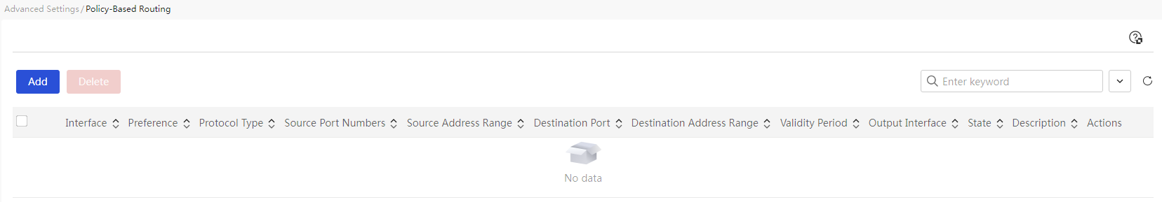
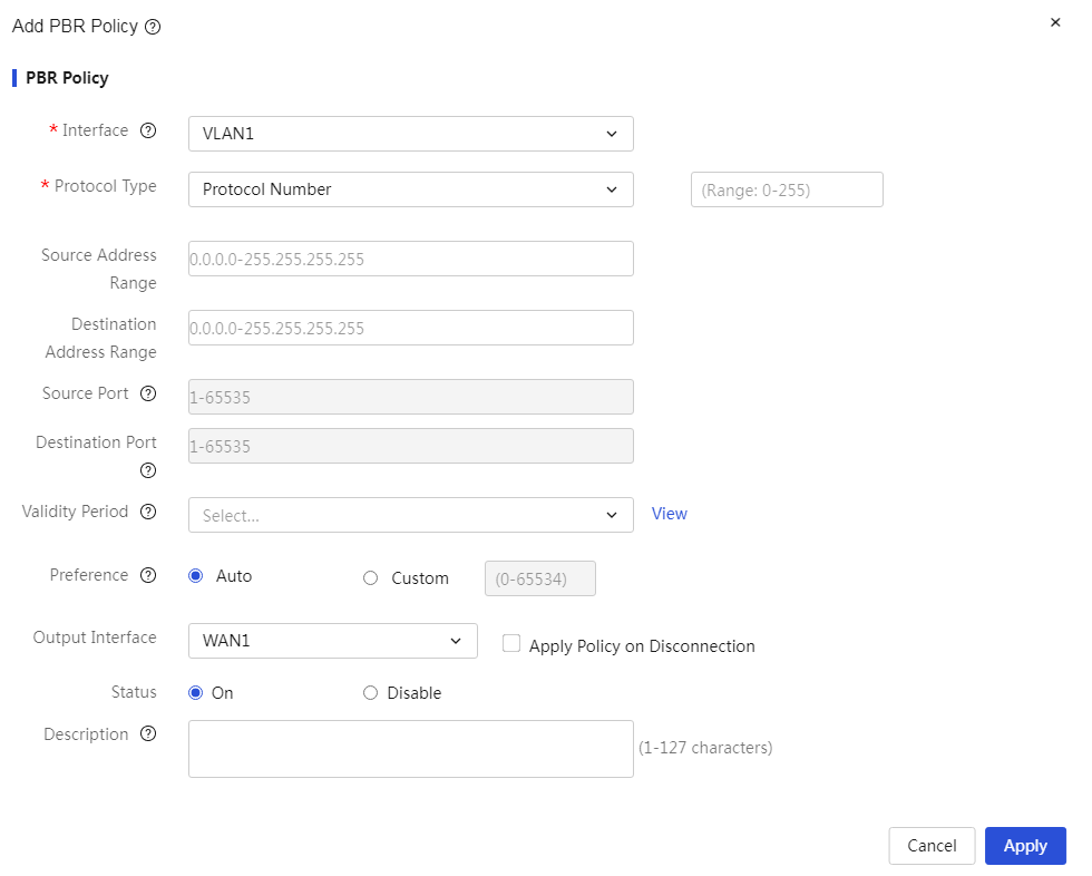
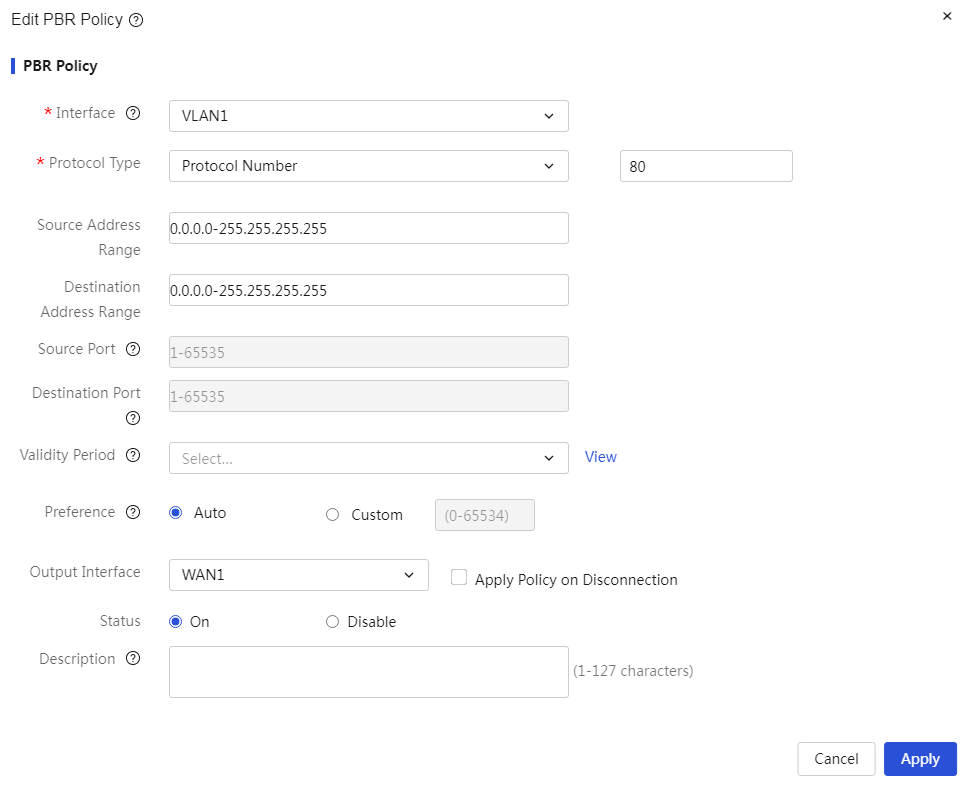
Parameters
Table 70 Parameter description
|
Parameter |
Description |
|
Ports |
The source interface of the packets, which means the policy controls the data packets received from a specific interface |
|
Protocol |
The types of packet protocols that the policy needs to control. When configuring this parameter, you can select as needed: · If you need to control packets of a certain transport layer protocol, select "TCP" or "UDP" · If you need to control packets of a certain network layer protocol, select "IP" · If you need to control ICMP protocol packets such as Ping or Tracert, select "ICMP" · If you need to control packets of other protocols, select "Protocol Number" and configure the protocol number |
|
Source IP Address Range |
The range of source IP addresses that the rule needs to control. When configuring this parameter, connect the starting and ending addresses with a hyphen, such as "1.1.1.1-1.1.1.2" · If only one address is specified, the starting and ending addresses must be the same · If you add "!" before the input address range or address, it means negation, meaning any address other than this address range or address will match, such as "!1.1.1.1-1.1.1.10" |
|
Destination IP Address Range |
The range of destination IP addresses that the rule needs to control. When configuring this parameter, connect the starting and ending addresses with a hyphen, such as "1.1.1.1-1.1.1.2" · If only one address is specified, the starting and ending addresses must be the same · If you add "!" before the input address range or address, it means negation, meaning any address other than this address range or address will match, such as "!1.1.1.1-1.1.1.10" |
|
Source port |
The source port that the rule needs to control. This parameter only needs to be configured when the protocol type is specified as "TCP" or "UDP." If you add "!" before the input port number, it means negation, meaning any port other than this port number will match, such as "!1-5000" |
|
Destination port |
The destination port that the rule needs to control. This parameter only needs to be configured when the protocol type is specified as "TCP" or "UDP." If you add "!" before the input port number, it means negation, meaning any port other than this port number will match, such as "!1-5000" |
|
Effective At |
The effective time of the rule. When configuring this parameter, you need to select a created time group. If you need to add a new time group, you can create a new time group by clicking the <Add Time Group> button on the right |
|
Priority |
The priority of the rule. There are two ways to set it: · Automatic: The system automatically assigns a priority to this rule, allocating it sequentially with a step of 5 based on the order of rule configuration · Custom: The user customizes the priority of the rule; a smaller value indicates a higher priority |
|
Output Interface |
The forwarding interface of the packets, meaning that the packets matching the rule are forwarded through the specified outgoing interface |
|
Forced |
When the WAN port's port status indicates that the external network is not connected, the policy-based routing pointing to that WAN port will become invalid. By configuring this parameter, you can force the policy-based routing to take effect when the WAN port's port status indicates that the external network is not connected. · If the "Force" option is selected, when the WAN port's port status indicates that the external network is not connected, the current policy-based routing will still take effect and forward data · If the "Force" option is not selected, when the WAN port's port status indicates that the external network is not connected, the current policy-based routing will not take effect |
|
Enabling state. |
Whether to enable this routing rule. If this rule is enabled, the device will operate according to the configured routing policy and rules |
|
Description |
The description information of the rule, which allows for a simple description of the rule for convenience |
|
Task |
You can edit and delete this configuration |
IPv6 static routes
About this task
IPv6 static routes are fixed routing entries manually configured in the router. When your IPv6 network structure is relatively simple and stable, configuring IPv6 static routes can achieve network intercommunication. For example, when you know the outgoing interface of the network and the IPv6 address of the gateway, setting the IPv6 static route will enable normal communication.
When multiple IPv6 static routes exist for the same destination, and you want to prioritize a specific IPv6 static route, you can adjust the precedence of the IPv6 static routes. The smaller the precedence value, the higher the priority of the corresponding static route.
Restriction and guidelinks
When the interface corresponding to the next hop in the IPv6 static route fails, the local IPv6 static route entry will not be deleted. In this case, you need to check the network environment and then modify the configuration of the IPv6 static route.
Procedure
Page wizard: [Advanced Options/IPv6 Static Route]
|
This page provides you with the following main functions: · Display details of added IPv6 static routes · Add IPv6 static routes · Delete added IPv6 static routes · Modify added IPv6 static routes · View the IPv6 routing information table |
|
|
Add IPv6 static routes: 1. Click the add button, and the add IPv6 static route dialog box will pop up. Enter the destination IP address, IPv6 prefix length, next hop, and other information. 2. Click Apply. |
|
|
Delete IPv6 static routes: 1. Select the IPv6 static route entries you wish to delete. 2. Click the delete button, and a confirmation dialog box will pop up. 3. Click Apply. |
|
|
Modify IPv6 static routes: 1. Click the edit icon in the operation column of the IPv6 static route you wish to modify, and the modify IPv6 static route dialog box will pop up. Modify the relevant parameters. 2. Click Apply. |
|
|
View the IPv6 routing information table: Click the view IPv6 routing information table button to see the routing information table. |
|
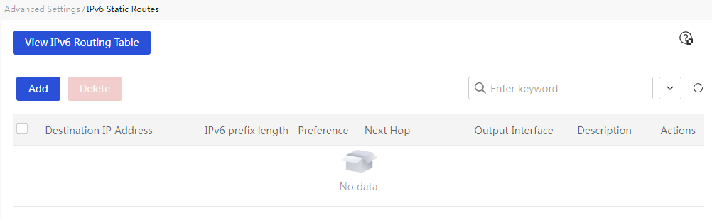
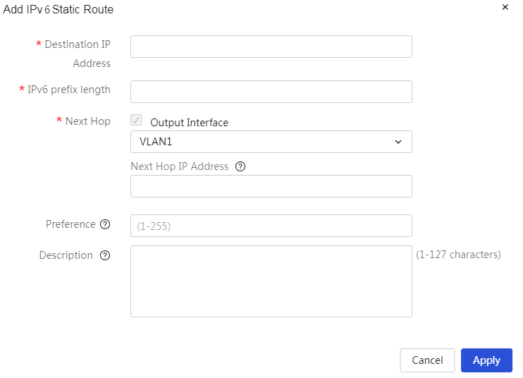
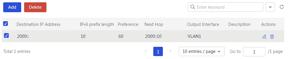
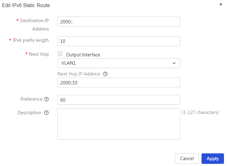
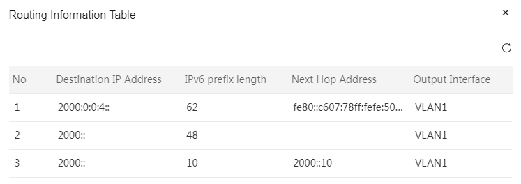
Parameters
Table 71 Parameter description
|
Parameter |
Description |
|
Destination IP Address |
IP address of the destination network that the device needs to access |
|
IPv6 prefix length. |
IPv6 prefix length of the destination network, for example, 64 |
|
Next hop |
The IP address of the next router that data needs to pass through before reaching the destination address. When configuring this parameter, you can select whether to check the "out interface" option as needed · If you confirm the device exit that the data will pass through, check the "out interface" option and set the next-hop IP address. The next-hop address must be in the same subnet as the selected interface · If you are unsure about the out interface, do not check the "out interface" option. By setting the next-hop IP address, the device can select an appropriate out interface on its own |
|
Priority |
Precedence of the IPv6 static route; when configuring this parameter, a smaller value indicates a higher precedence |
|
Description |
Description of the rule; you can provide a brief description of the rule for convenience |
|
Task |
You can edit and delete this configuration |
Use system tools
Configure system settings
Introduction
This function allows you to set device information and system time. Device information includes device name, device location, and contact information for the network administrator, facilitating the management and localization of devices. System time includes date, time, and time zone, etc. To aid in device management and ensure that this device collaborates effectively with other network devices, you need to configure the device with accurate system time.
You can use the following methods to obtain the system time:
· Manually set the date and time--After you specify the date and time, the device will use its internal clock signal for timing. If the device restarts, the system time will be reset to the factory default.
· Automatic time synchronization--The device uses the time obtained from the NTP server as the current system time and periodically synchronizes the time with the NTP server. The device can resynchronize the system time of the NTP server after it restarts. As a best practice, use automatic time synchronization if an NTP server is available in your network to provide more accurate time.
Device Info
About this task
To better assist network administrators in managing devices within the network, it is necessary to set device information, which includes the device's name, location, and contact information for the network administrator.
Procedure
Page wizard: [System Tools/System Settings/Device Information]
|
Set device information, including device name, device location, and network administrator's contact information. |
|
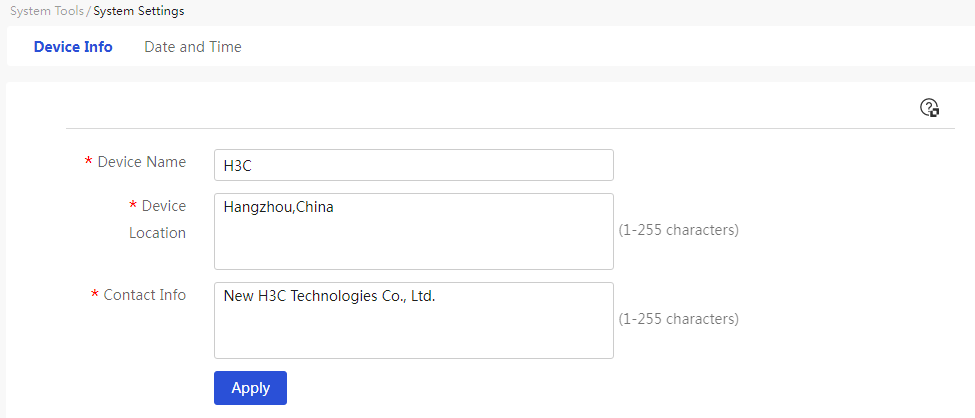
Parameters
The meanings of various parameters on the page are shown in the table below.
Table 72 Parameter description
|
Parameter |
Description |
|
Device name |
Enter the name of the device |
|
Device location |
Enter the location of the device |
|
Contact information |
Enter the contact information of the network administrator |
Date and time
About this task
Set the system time using the following two methods:
· Manually set the date and time—
· Automatic date and time synchronization—
Obtain the time zone of the device. Configure the time zone of the device as the time zone of the geographical area where the device is located. For example, if the device is in China, select Beijing, Chongqing, Hong Kong SAR, Urumqi (GMT+08:00). If the device is in the United States, select Central Time (US & Canada) (GMT-06:00).
Procedure
Page wizard: [System Tools/System Settings/Date and Time]
|
Set System Time |
|
|
Click "Manually Set Date and Time" to configure the system time to the current time of the device's geographical area: 1. Select Year, Month, and Day 2. Select Hour, Minute, and Second 3. Configure the time zone to the time zone of the device's geographical area 4. Click < Apply > button to complete the configuration |
|
|
Select the "Auto Synchronize Network Date and Time" option, and the device will automatically choose the system time from either NTP Server 1 or NTP Server 2 as the device's system time. If the preferred server fails, the device will automatically use the system time from the other NTP server. If both NTP servers fail, the device will continue to keep time using its internal clock signal, and will synchronize with the NTP server's time once it recovers: 1. In the "NTP Server 1" configuration item, enter the IP address or domain name of NTP Server 1 2. In the "NTP Server 2" configuration item, enter the IP address or domain name of NTP Server 2. Configure the time zone to the time zone of the device's geographical area 3. Configure the time zone to the time zone of the device's geographical area 4. Click < Apply > button to complete the configuration |
|
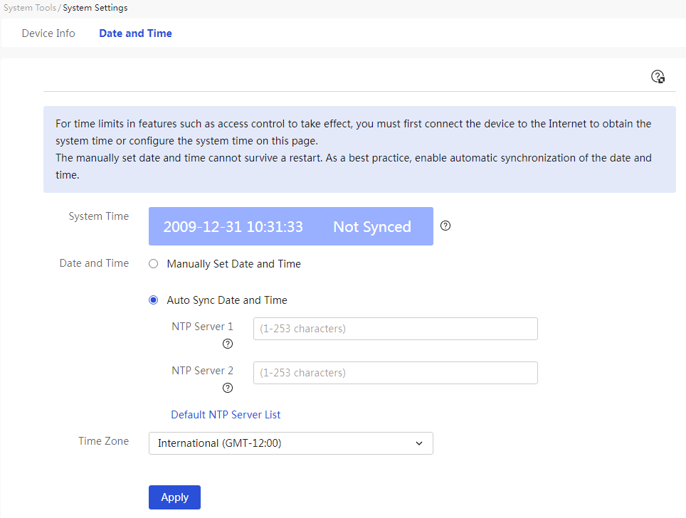
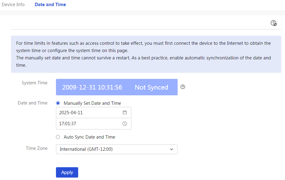
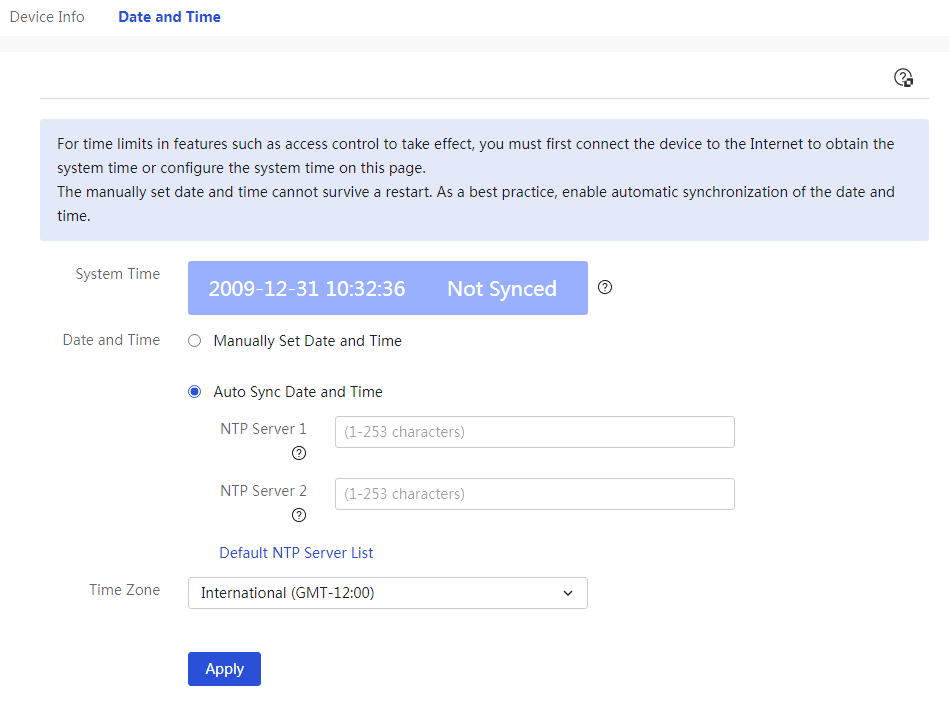
Parameters
The meanings of various parameters on the page are shown in the table below.
Table 73 Parameter description
|
Parameter |
Description |
|
System time |
Current System Status |
|
Manually set the date and time |
Manually set the system date and time. If the device restarts, the system time will revert to the factory time. |
|
Configure automatic date and time synchronization |
Automatically synchronize the network date and time. The device and the NTP server must have the same time zone configured; otherwise, it will cause a discrepancy between the device's system time and the NTP server's system time. |
|
NTP Server 1 |
Enter the IP address or domain name of NTP Server 1. |
|
NTP Server 2 |
Enter the IP address or domain name of NTP Server 2. |
|
Default NTP Server List |
View the built-in NTP server information of the device. |
|
Time Zone |
The time zone of the device. |
|
Applications |
Complete Configuration |
Perform network diagnosis
Configure ping
Procedure
Page wizard: [System Tools/Network Diagnostics/Ping]
|
Used to detect the network and test whether another device or host is reachable. |
|
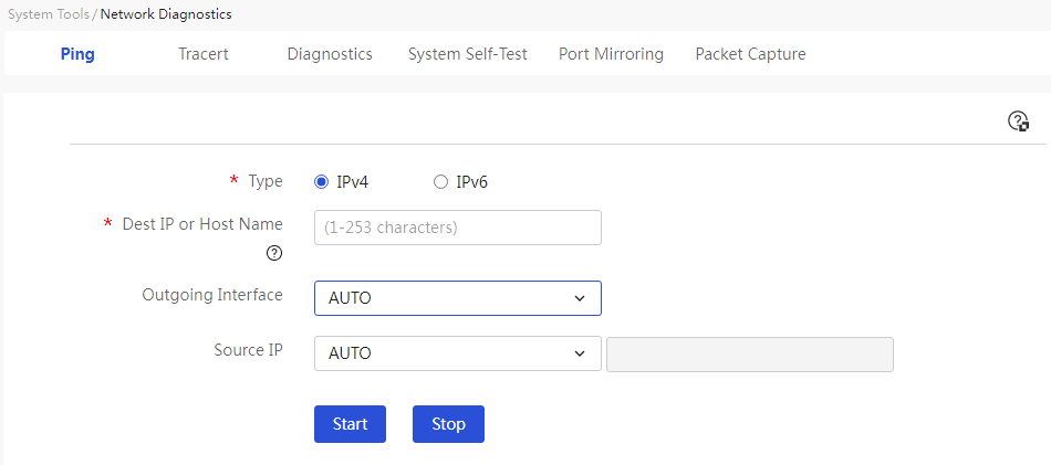
Parameters
The meanings of various parameters on the page are shown in the table below.
Table 74 Parameter description
|
Parameter |
Description |
|
Type |
Type of Ping Operation |
|
IPv4 |
Operate using IPv4 protocol, with message type and address format as IPv4 |
|
IPv6 |
Operate using IPv6 protocol, with message type and address format as IPv6 |
|
Destination IP or Host Name |
Enter the target IP address or host name for the Ping operation. Input of characters such as \ ' " < > ; & ` # and Chinese characters, as well as spaces, is not supported. If the target IP address is the source IP address of the device, please select the interface as AUTO. |
|
Select Outgoing Interface |
Select the device interface to reach the target IP address or host name. When "AUTO" is selected, it means the device automatically chooses an interface to forward the Ping message. |
|
Source IP address |
Select the source IP address for the Ping operation. When "AUTO" is selected, it means the device automatically selects the source IP address for the Ping operation; when "Source IP Address" is selected, you need to manually enter the source IP address for the Ping operation. |
|
Start |
The system starts detection |
|
Stopped |
The system stops detection |
|
Result. |
Display the detection process and results, indicating the status of network packet testing and the round-trip average latency with the test host. |
Configure tracert
Procedure
Page wizard: [System Tools/Network Diagnostics/Tracert]
|
Used to check the routing situation from the standby device to the destination host. |
|
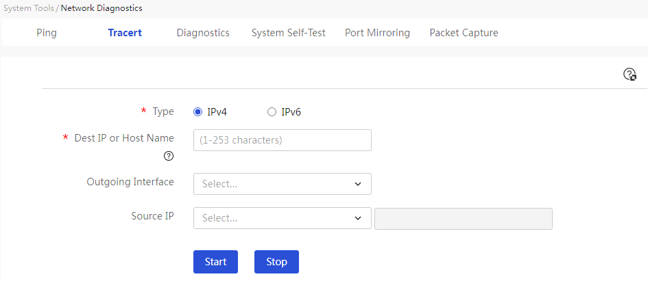
Parameters
The meanings of various parameters on the page are shown in the table below.
Table 75 Parameter description
|
Parameter |
Description |
|
Type |
Type of Tracert Operation |
|
IPv4 |
Operate using the IPv4 protocol, with message type and address format as IPv4 |
|
IPv6 |
Operate using the IPv6 protocol, with message type and address format as IPv6 |
|
Destination IP or Host Name |
Input the target IP address or host name for routing trace |
|
Select Outgoing Interface |
Select the device interface to the target IP address or host name. When "AUTO" is selected, the device automatically chooses an interface to forward the Tracert message |
|
Source Address |
Select the source IP address for the Tracert operation. When "AUTO" is selected, the device automatically chooses the source IP address for the Tracert operation; when "Source IP Address" is selected, you need to manually input the source IP address for the Tracert operation |
|
Start |
The system starts detection |
|
Stopped |
The system stops detection |
|
Result. |
Display the detection process and results |
Collect diagnostic information
Procedure
Page wizard: [System Tools/Network Diagnostics/Diagnosis]
|
The diagnostic information consists of operational information from each functional module, used for problem identification. The device will automatically save this information as a ZIP file to your terminal equipment (TE). |
|
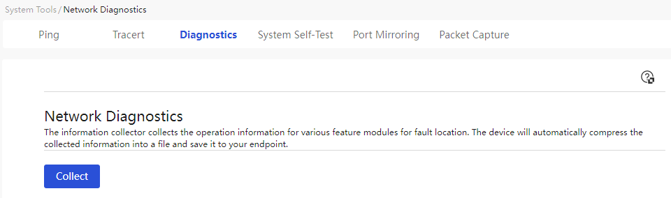
Parameters
The meanings of various parameters on the page are shown in the table below.
Table 76 Parameter description
|
Parameter |
Description |
|
Network Diagnosis |
The system has started collecting diagnostic information. |
Perform a system self-test
Procedure
Page wizard: [System Tools/Network Diagnostics/System Self-Test]
|
Used to check the current operation and configuration status of the device, providing feedback on whether the device configuration is reasonable and whether the device is operating normally, among other information. |
|
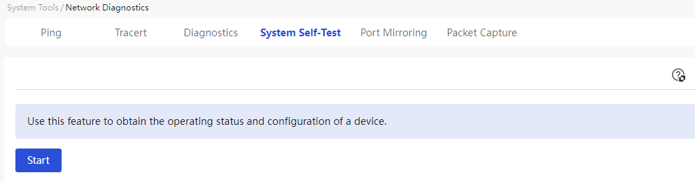
Parameters
The meanings of various parameters on the page are shown in the table below.
Table 77 Parameter description
|
Parameter |
Description |
|
Self-Check |
The system performs a self-check and displays the results. |
Port mirroring
Procedure
Page wizard: [System Tools/Network Diagnostics/Port Mirroring]
|
Automatically copies packets from the mirrored port to the mirror port, providing real-time detailed information on the transmission status of each port, facilitating network management personnel in traffic monitoring, performance analysis, and fault diagnosis. |
|
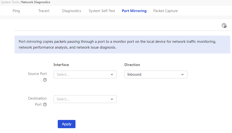
Parameters
The meanings of various parameters on the page are shown in the table below.
Table 78 Parameter description
|
Parameter |
Description |
|
Source port |
Select the source port for mirroring, which is the monitored port |
|
Direction |
Select the orientation for mirroring: · If you select "In orientation," it means only copy the packets received by the source port · If you select "Out orientation," it means only copy the packets sent by the source port · If you select "Both directions," it means to copy both the packets received and sent by the source port |
|
Destination port |
Select the destination port for mirroring, which is the port connected to the data monitoring device |
|
OK |
The system starts port mirroring |
Capture packets
Procedure
Page wizard: [System Tools/Network Diagnostics/Packet Capture Tool]
|
Used to capture network datagrams for more effective analysis of network outages. After the packet capture is complete, it will automatically export the captured file "capture-******.pcap" for the user to save locally. |
|
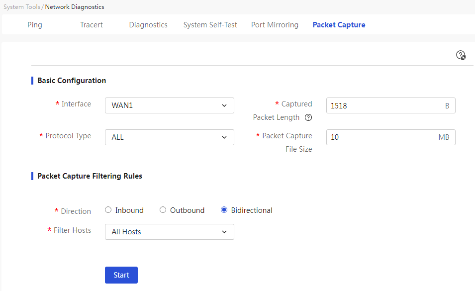
Parameters
The meanings of various parameters on the page are shown in the table below.
Table 79 Parameter description
|
Parameter |
Description |
|
Ports |
Select the interface from which to capture data, supporting all WAN, VLAN, and other interfaces of the current router. |
|
Captured Packet Length |
Input the capture length of the data packets, measured in bytes. If the packet length exceeds this value, the packet will be truncated. Note that using a longer capture length increases processing time and reduces the number of packets that can be cached, which may lead to packet loss. Therefore, the smaller the capture length, the better, as long as it can still capture the desired packets. |
|
Protocol |
Select the protocol types to filter. Choosing ALL will capture all packets on the current interface. |
|
Packet Capture File Size |
Input the size of the captured packets, measured in MB. |
|
Duration |
Input the duration of the capture, measured in seconds. |
|
Direction |
Select the direction of the captured packets, mainly divided into: · Inbound: Indicates capturing only the packets received by the port. · Outbound: Indicates capturing only the packets sent by the port. · Bidirectional: Indicates capturing both the packets received and sent by the port. Default is bidirectional. |
|
Source Host |
Select the source host for capturing packets. |
|
Destination Host |
Select the destination host for capturing packets. |
|
Filter Hosts |
Select the filtering host for capturing packets. |
|
All Hosts |
Filter by source or destination host, i.e., capture packets from all source/destination hosts. |
|
IP Address Filtering |
You need to set the host's IP address. |
|
MAC filter |
You need to set the host's MAC address. |
|
Start |
The system begins capturing packets. The capture process and the current number of captured packets are displayed on this page. |
|
Cancel |
During the packet capture process, you can terminate the current operation and export the captured file “capture-******.pacp”. |
Remote management
Configure ping
Procedure
Page wizard: [System Tools/Remote Management/Ping]
|
By using the ping |
|
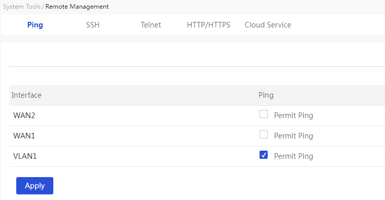
Parameters
The meanings of various parameters on the page are shown in the table below.
Table 80 Parameter description
|
Parameter |
Description |
|
Allow Ping |
Select the “Allow Ping” option corresponding to the interface in the list to set the interface to receive (Rx) Ping packets. |
|
Applications |
Complete Configuration |
SSH protocol
Procedure
Page wizard: [System Tools/Remote Management/Telnet]
|
SSH (Secure Shell) is an encrypted network protocol used for remote login, file transfer, and command execution on an unsafe network in a safety ground. |
|
|
In the "Administrator List" section, click < the Add/Edit > button to pop up the Add/Edit Administrator List. |
|
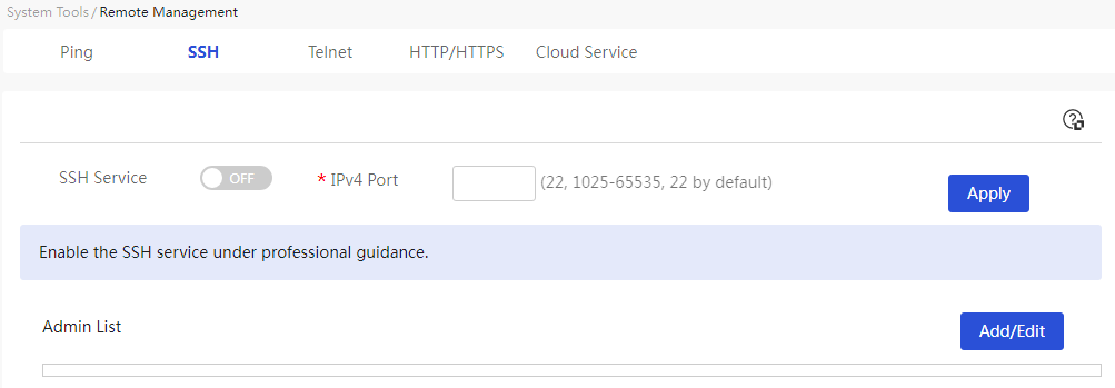
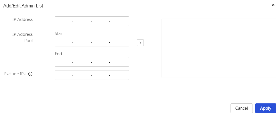
Parameters
The meanings of various parameters on the page are shown in the table below.
Table 81 Parameter description
|
Parameter |
Description |
|
SSH Service |
Enable the SSH service. If this service is enabled, the computer can remotely manage this device via SSH through the WAN port. |
|
IPv4 Port |
The port number for remote management of the device via SSH. External users can log in to the device for management through this port number. The default value is 22. |
|
IP address |
The IP address for accessing the device via SSH. When configuring this parameter, after entering the IP address, you need to click the > button on the right side of the configuration item to submit the configured address. |
|
IP Range |
The starting and ending addresses of the IP address range for accessing the device via SSH. When configuring this parameter, after entering the IP address range, click the > button on the right side of the configuration item to submit the configured address. |
|
Excluded addresses |
The IP addresses that are not allowed to access the device via SSH. When configuring this parameter, after entering the exclusion address range, click the > button on the right side of the configuration item to submit the configured address. |
Telnet
Procedure
Page wizard: [System Tools/Remote Management/Telnet]
|
Telnet is a protocol that enables remote login services. Users can log into devices via Telnet on their PC for remote management of the devices. |
|
|
In the "Administrator List" section, click the <Add/Edit> button to open the Add/Edit Administrator List. |
|
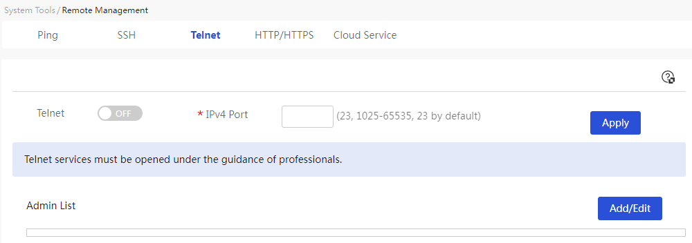
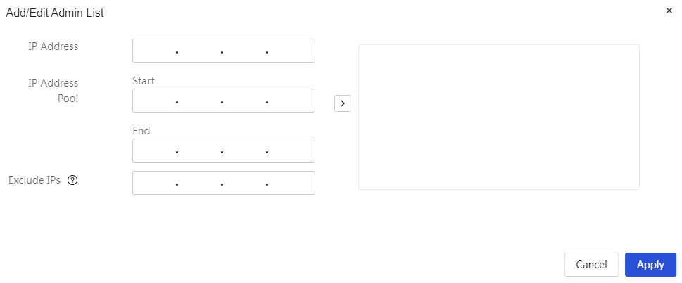
Parameters
The meanings of various parameters on the page are shown in the table below.
Table 82 Parameter description
|
Parameter |
Description |
|
Telnet Service |
· Click the button to set the button status to "ON" to enable the Telnet service · Click the button to set the button status to "OFF" to disable the Telnet service |
|
IPv4 Port |
Enter the port number for remote management of the device via Telnet. External users log in to the device for management through this port. |
|
Add/Edit |
Click < the Add/Edit > button to pop up the Add/Edit Administrator List dialog box |
|
IP address |
Enter the IP address allowed to access the device via Telnet |
|
IP Range |
Allowed IP address range for Telnet access to the device |
|
Start |
Starting address of the IP address range allowed for Telnet access to the device |
|
Terminate |
Ending address of the IP address range allowed for Telnet access to the device |
|
Excluded addresses |
Enter the IP address not allowed to access the device via Telnet |
|
OK |
Complete Configuration |
HTTP/HTTPS
|
|
NOTE: When the administrator changes the VLAN1 network segment, the VLAN1 management address range will automatically change accordingly. |
Procedure
Page wizard: [System Tools/Remote Management/HTTP/HTTPS]
|
Two Web login methods based on Hypertext Transfer Protocol (HTTP) and HTTPS. The security performance of the HTTPS login method is higher than that of the HTTP login method. Users can log in to the device's Web interface using the HTTP/HTTPS protocol on a PC, allowing them to intuitively configure and manage the device through the Web interface. |
|
|
In the "VLAN1 Management Address" section, click < Edit > button to edit the VLAN1 management address. |
|
|
In the "Custom Management Address" section, click < Add/Edit > button to add/edit the custom management address. |
|
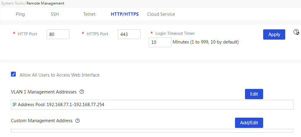
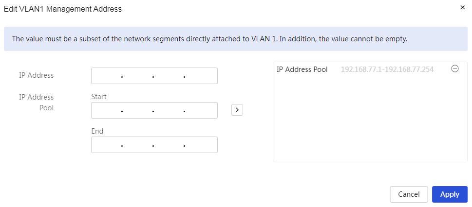
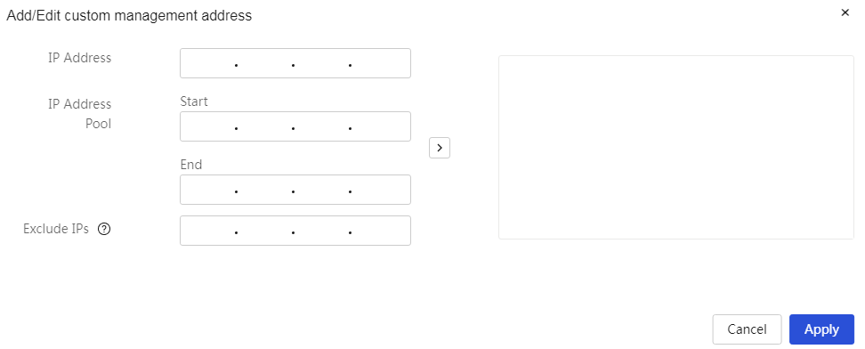
Parameters
The meanings of various parameters on the page are shown in the table below.
Table 83 Parameter description
|
Parameter |
Description |
|
HTTP Login Port |
Enter the port number corresponding to the device for HTTP login. As a best practice, use a port number above 10000. |
|
HTTPS Login Port |
Enter the port number corresponding to the device for HTTPS login. As a best practice, use a port number above 10000. |
|
Login Timeout |
Enter the idle timeout for the web management page, defaulting to 10 minutes. After the administrator logs into the web management page, if the idle time exceeds the login timeout, the system will automatically log out that administrator. This parameter takes effect at the administrator's next login. |
|
Allow All Users to Access WEB |
Selecting this option allows all users to access the WEB. |
|
VLAN1 Management Address |
Edit VLAN1 management address |
|
Edit |
Add allowed administrator IP addresses or address ranges to access the web management page |
|
IP address |
Enter the IP address allowed to access the device via HTTP/HTTPS |
|
IP Range |
Enter the starting and ending addresses of the IP address range allowed to access the device via HTTP/HTTPS |
|
Starting |
Enter the starting address of the IP address range allowed to access the device via HTTP/HTTPS |
|
Terminate |
Enter the ending address of the IP address range allowed to access the device via HTTP/HTTPS |
|
Custom Management Address |
Add/Edit custom management address |
|
Add/Edit |
Add allowed administrator IP addresses or address ranges to access the web management page |
|
IP address |
Enter the IP address allowed to access the device via HTTP/HTTPS |
|
IP Range |
Enter the IP address range allowed to access the device via HTTP/HTTPS |
|
Starting |
Enter the starting address of the IP address range allowed to access the device via HTTP/HTTPS |
|
Terminate |
Enter the ending address of the IP address range allowed to access the device via HTTP/HTTPS |
|
Excluded addresses |
Enter the IP address not allowed to access the device via HTTP/HTTPS |
|
OK |
Complete Configuration |
Cloud Service
Procedure
Page wizard: [System Tools/Remote Management/Cloud Services]
|
Manage devices on the cloud platform |
|
|
Unbind cloud services and terminate the binding relationship |
|
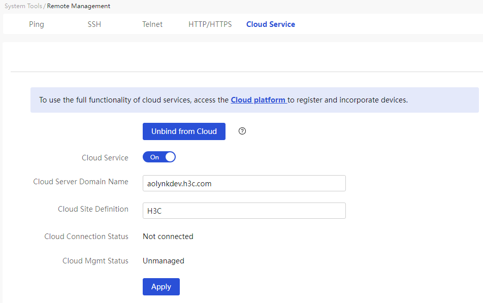
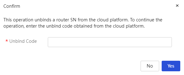
Parameters
The meanings of various parameters on the page are shown in the table below.
Table 84 Parameter description
|
Parameter |
Description |
|
Unbind Cloud Service |
Remove Cloud Service Binding |
|
Unbinding Code |
Enter the unbinding code obtained from the cloud platform |
|
Cloud Service |
· If the button status is "On", the cloud service will be activated · If the button status is "Off", the cloud service will be deactivated |
|
Cloud Platform Server Domain Name |
Enter the H3C cloud platform domain name |
|
Cloud Venue Definition |
Enter the system name of the device. The length of the cloud venue definition must be 1-64 characters and can only include digits, letters, underscores, hyphens, and spaces. It cannot be in Chinese and cannot be entirely spaces |
|
Cloud Connection Status |
Current cloud connection status |
|
Cloud Management Status |
Current cloud management status |
|
Applications |
Complete Configuration |
Configuration management
|
|
NOTE: Support for the above functions may vary for different device models; please refer to the actual display on the web page. |
This function is used to manage the device's configuration file. The configuration file refers to the file used to save the device configuration.
With configuration management, you can perform the following tasks:
· Restore the factory defaults—This task restores the configuration to the factory defaults. If the device does not have a startup configuration file or the startup configuration file is corrupt, perform this task so that the device can start up at the next startup.
· Restore the configuration from a backup file—This task replaces the running configuration with the configuration from a backup file. Perform this task if the running configuration contains incorrect or undesirable settings.
· Export current configuration: If you wish to export the current configuration file as a backup configuration file, you need to use this function to export the current configuration file.
Restore factory defaults
Procedure
Page wizard: [System Tools/Configuration Management/Restore Factory Configuration]
|
If the device does not have a configuration file or if the configuration file is damaged, and you want the device to start and operate normally, you need to use this function to restore the configuration on the device to factory settings. |
|
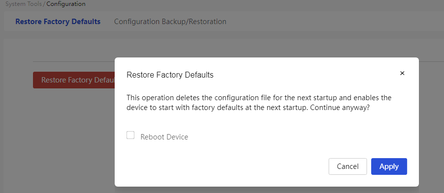
Parameters
The meanings of various parameters on the page are shown in the table below.
Table 85 Parameter description
|
Parameter |
Description |
|
Restore factory defaults |
Restore the device's configuration to factory settings |
|
Restart the device immediately |
The system will restart the device immediately |
|
OK |
Execute this operation |
|
Cancel |
Cancel this operation |
Backup/restore configuration
|
|
NOTE: · You can restore the device configuration only from a .rar backup file. · Ensure stable and normal power supply during device configuration restoration. · After configuration restoration is completed, the device will restart with the new configuration automatically. |
Procedure
Page wizard: [System Tools/Configuration Management/Backup/Restore Configuration]
|
· After a device configuration error, if you want the device to recover to the correct configuration operating state, you need to use the “recovery from backup file” function to restore the device configuration. · If you want to export the current configuration file as a backup configuration file, you need to use the “export current configuration” function to export the current configuration file. |
|
|
Click < recovery from backup file > button to enter the recovery from backup file page: 1. Click the “upload file” button and select the backup configuration file from a specific path. 2. Click < confirm > button to start the configuration recovery. |
|
|
Click < export current configuration > button to export the current configuration. |
|
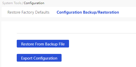
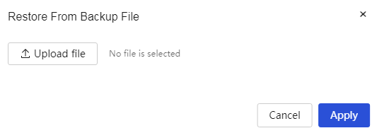

Parameters
The meanings of various parameters on the page are shown in the table below.
Table 86 Parameter description
|
Parameter |
Description |
|
Restore configuration from a backup file |
After a device configuration error, if you want the device to recover to the correct configuration operating status, you need to use this function to recover the device configuration. |
|
Export the running configuration |
If you want to export the current configuration file as a backup configuration file, you need to use this function to export the current configuration file. |
Upgrade the system
|
|
NOTE: · Save the configuration on the router before you upgrade the software. You use the information to restore the system when an issue occurs during the upgrade process. · After you upload the software image, the router upgrades the software automatically and then restarts. · For the router to operate correctly, do not power off the router during the upgrade process. · As a best practice to avoid incompatibility issues, do not use an image file with a lower version or released earlier than the current software. |
Manually upgrade the software
Restriction and guidelinks
Before manual upgrade, access the Network Security > DDoS Attack Defense > Abnormal Traffic Defense page to identify whether abnormal traffic defense is enabled. If it is enabled, disable it, and then perform a manual upgrade.
Procedure
Page wizard: [System Tools/System Upgrade/Manual Upgrade]
|
Upgrade the device version manually to address current software vulnerabilities or update application functions. |
|
|
Click < the manual update system software > button to pop up the manual update system software dialog box: · If you need the device to restore factory settings after upgrading the system software, select the “Restore Factory Settings” option; if you do not need the device to restore factory settings after upgrading the system software, do not select the “Restore Factory Settings” option. · Click < OK > button to start the software upgrade. |
|
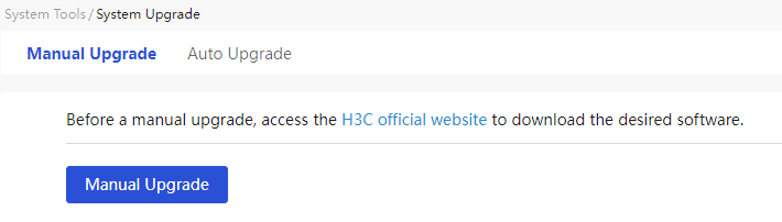
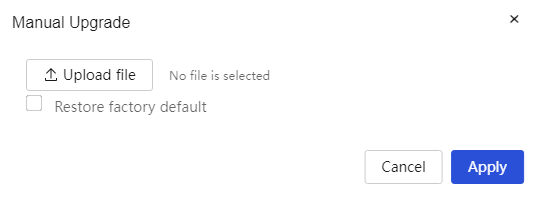
Parameters
The meanings of various parameters on the page are shown in the table below.
Table 87 Parameter description
|
Parameter |
Description |
|
Manual System Software Upgrade |
Upgrade the device version through a manual system software upgrade |
|
Restore factory defaults |
The device will restore factory settings after upgrading the system software |
|
OK |
Start Software Upgrade |
Auto update
Procedure
Page wizard: [System Tools/System Upgrade/Automatic Upgrade]
|
Automatically upgrade the system software on the device through the H3C cloud platform to fix current software version vulnerabilities or update application functions. |
|
|
Set the time for detection, and the system will check for new version software based on the set time. If it detects new version software, the system will perform an immediate upgrade. |
|
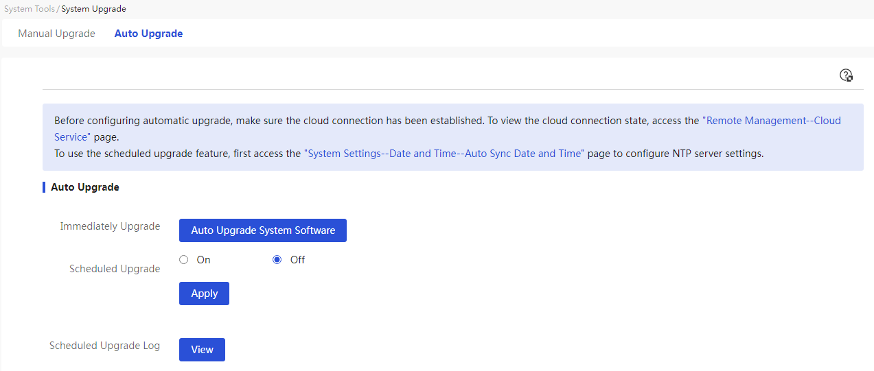
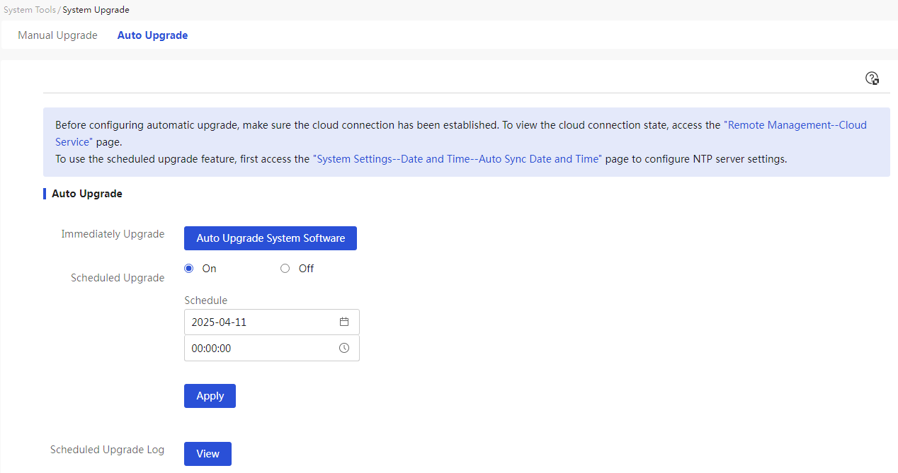
Parameters
The meanings of various parameters on the page are shown in the table below.
Table 88 Parameter description
|
Parameter |
Description |
|
Automatic Upgrade of System Software |
Immediately perform automatic upgrade operations on the system software |
|
Scheduled Upgrade |
Schedule automatic upgrade operations on the system software by detecting the time settings. Before performing the automatic upgrade, ensure that the cloud connection status is connected; otherwise, the automatic upgrade will fail. |
|
Detection Time Settings |
Set the time for detection. The system will check for new version software based on the set time. If a new version is detected, the system will immediately upgrade the software. |
|
Applications |
Complete Configuration |
|
View |
View Scheduled Upgrade Logs |
Restart the device
Use this feature to restart the device immediately or configure scheduled device restart.
Immediate restart
Restriction and guidelinks
A device restart might result in service interruption. Perform this task with caution.
Procedure
Page wizard: [System Tools/Restart/Immediate Restart]
|
Restart the device immediately |
|
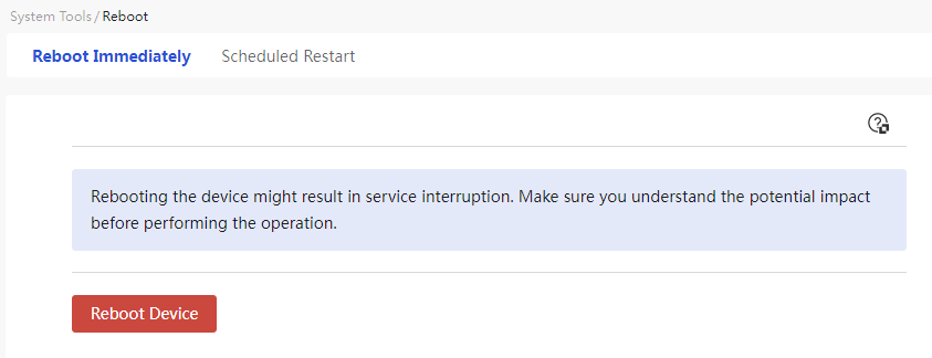
Parameters
The meanings of various parameters on the page are shown in the table below.
Table 89 Parameter description
|
Parameter |
Description |
|
Restart the device immediately |
Restart the device immediately |
Scheduled restart
|
|
NOTE: Scheduled restart depends on successful NTP synchronization. To use scheduled restart, first navigate to the System Tools > System Settings > Date and Time page, select Auto Sync Date and Time, and specify an NTP server. |
Procedure
Page wizard: [System Tools/Restart/Scheduled Restart]
|
Timing restart device |
|
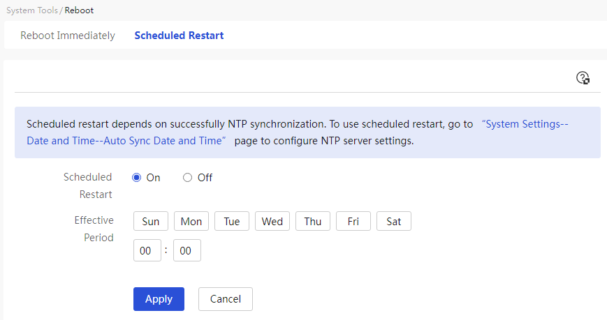
Parameters
The meanings of various parameters on the page are shown in the table below.
Table 90 Parameter description
|
Parameter |
Description |
|
Scheduled restart |
Timing to Restart Device |
|
ON |
Enable the timing restart function for the device |
|
OFF |
Disable the timing restart function for the device |
|
Effective Period |
Set the specific time for the device to restart weekly |
|
OK |
The device will restart at the set time |
System logs
The device generates system logs during operation. The logs record the configurations made by the administrator on the device, changes in the device's status, and important events occurring within the device, providing references for user maintenance and fault diagnosis.
You can send logs to log servers for centralized management or view logs directly on the Web page.
The logs are divided into five levels, as shown in the table below, with severity decreasing from 0 to 4. Understanding log levels can help you quickly filter out key logs.
Table 91 Log severity
|
Severity value |
Level |
Description |
|
0 |
Error(0) |
Error condition. |
|
1 |
Warning(1) |
Warning condition. |
|
2 |
Notification(2) |
Normal but significant condition. |
|
3 |
Informational(3) |
Informational message. |
|
4 |
Debugging(4) |
Debugging message. |
System logs
Restriction and guidelinks
Make sure the device and the log server can reach each other.
Procedure
Page wizard: [System Tools/System Logs]
|
Manage and display log information |
|

Parameters
The meanings of various parameters on the page are shown in the table below.
Table 92 Parameter description
|
Parameter |
Description |
|
Log management |
Log management |
|
Log Recording Level |
Select the level of log recording |
|
Log Sources |
Select the source of the logs to control the output of log information |
|
System |
Record information related to the operating status of certain functional modules during device operation. This parameter is selected by default and cannot be deselected. |
|
Task |
Record information about changes in device configuration |
|
Security |
Record information related to device protection against attacks, message filtering, firewall, etc. |
|
Traffic Info |
Record traffic information such as IP and port |
|
VPN |
Record VPN-related information |
|
Whether to log system logs to storage media |
· Selecting this option indicates that system logs will be recorded to storage media · Deselecting indicates that system logs will not be recorded to storage media |
|
Send to Log Server |
Enter the IP address or domain name of the log server |
|
Applications |
Complete Configuration |
|
Advanced Search |
Find corresponding system logs using any combination of time, level, information source, and details |
|
Time |
Find corresponding system logs by time |
|
Level. |
Find corresponding system logs by level |
|
Information Source |
Find corresponding system logs by information source |
|
Details |
Find corresponding system logs by details |
|
Clear |
Clear the log information recorded by the router |
|
Export |
Export existing log information from the device to the PC that logged into the web management page |
