| Title | Size | Downloads |
|---|---|---|
| H3C UIS HCI Cloud Migration Guide-5W101-book.pdf | 5.32 MB |
- Table of Contents
- Related Documents
-
| Title | Size | Download |
|---|---|---|
| book | 5.32 MB |
|
|
|
H3C UIS HCI |
|
Cloud Migration Guide |
|
|
|
|
Document version: 5W101-20221201
Copyright © 2022 New H3C Technologies Co., Ltd. All rights reserved.
No part of this manual may be reproduced or transmitted in any form or by any means without prior written consent of New H3C Technologies Co., Ltd.
Except for the trademarks of New H3C Technologies Co., Ltd., any trademarks that may be mentioned in this document are the property of their respective owners.
The information in this document is subject to change without notice.
Contents
Gathering business information
Gathering physical server information
Assessing the configuration after migration
Assessing data volume and time required for migration
Troubleshooting VMware VM migration
Migration of a VM fails after the snapshot for that VM is deleted
Failed to add an external cluster to UIS Manager
The system prompts snapshot deletion failure and the migration fails
Heterogeneous migration configuration guide
Installing the heterogeneous migration component
Installation package selection
Error messages and exceptions in the Web interface
A VM that uses the SUSE 11 operating system cannot start after migration
Exporting VMs as OVA or OVF templates
Migrating a VM through the cloud rainbow feature in UIS Manager
Hardware and software requirements
Performing online VM migration
The VM migration process is stuck in 99%
Migrating a VMware VM from the CLI
Appendix Gathering physical host and VM migration information
Gathering operating system information for a physical host
Gathering hardware configuration
Gathering hardware configuration
Gathering information by using Linux commands
Gathering VM migration information
Gathering business system type information
About UIS HCI cloud migration
This document helps you plan, design, and implement the process of migrating your businesses to UIS HCI.
Application scenarios
The UIS HCI cloud migration solution enables you to migrate business systems to UIS Manager. Based on the migration service provided by UIS HCI, you can gather VM information and determine the migration solution to ensure a successful business migration to UIS.
Business migration workflow
To migrate businesses to UIS, use the following workflow.
Figure 1 Business migration workflow
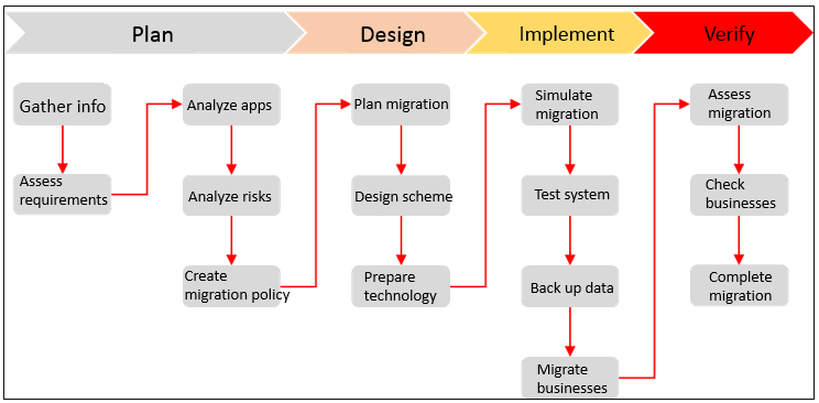
Table 1 Business migration workflow
|
Phase |
Activities |
|
Gathering information |
Service experts gather business migration requirements and live network information based on the information collection template. |
|
Assessment and analysis |
Assess and plan service migration. |
|
Solution design |
Based on the assessment and analysis of VM migration, design an appropriate migration scheme to ensure migration reliability and reduce down time. |
|
Migration |
Migrate businesses as planned. |
|
Business verification and testing |
Verify and test the business system after migration to verify that the business system is running correctly on UIS. |
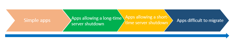
As a best practice, migrate applications in the business system in the following order:
1. Simple applications.
2. Applications that allow a long-time server shutdown.
3. Applications that allow only a short-time server shutdown.
4. Applications that are difficult to migrate.
For example, you can first migrate stateless applications, public service component systems, non-cluster systems, and then migrate cluster systems, core business systems, and core databases.
Figure 2 Recommended business migration order
Gathering business information
To ensure smooth migration of businesses, first gather business information, including business system information, migration requirements, IT environment information, and database system information. Then, assess migration risks, and select an appropriate migration method and hardware configuration.
Gathering physical server information
Gathering server information
You gather hardware and application system information for physical servers. Hardware configuration information includes server model, CPU, memory, and disk information. Application system information includes operating system, compatibility with x86, system specifications, CPU load, memory load, disk usage, application deployment, peripherals, and NIC quantity information.
Table 2 Physical server information
|
Item |
Business system |
Data analysis Windows client, C/S model |
|
Hardware configuration |
Server model |
Dell PowerEdge T410 |
|
CPU |
Intel Pentium Xeon processor (4 CPUs), 2.1GHz |
|
|
Memory |
2048MB RAM |
|
|
Disk |
2*512GB |
|
|
Application system information |
Operating system |
Windows 2003 Enterprise, 64-bit |
|
Compatible with x86 |
Yes/No |
|
|
Technical specifications |
4-core, 8G memory, 500G disk capacity |
|
|
CPU load |
Peak: 30% Average: 10% |
|
|
Memory load |
Peak: 60% Average: 20% |
|
|
Disk usage |
20%, 0G/month |
|
|
Peripherals and NICs |
USB encryption, 2 NICs |
|
|
External storage |
No |
When you gather physical server information, follow these restrictions and guidelines:
· The Linux kernel version is not lower than 2.6.25. When you perform heterogeneous migration, virtio is incompatible at UIS side if the Linux kernel version is lower than 2.6.25.
· The server is not using NAS storage, for example, NFS/CIFS/Samba. If the server is using NAS storage, heterogeneous migration is not supported.
· Identify whether disaster recovery is required and determine the backup mode after migration as needed.
· Identify whether the Windows desktop system is used.
Gathering database system information
You must investigate database system indicators and evaluate the infrastructure for UIS HCI products to meet the requirements of database deployment. Database information that needs to be gathered includes the database type and version, database deployment architecture, database instance flavors, operating system, database capacity, concurrent users, and performance requirements.
Table 3 Database system information
|
Database version |
MySQL5.7 |
|
Database deployment mode |
3, one primary and two backups |
|
Database instance flavor |
Intel(R) Pentium(R) III Xeon processor (4 CPUs), 2.1GHz, 2048MB RAM |
|
Operating system |
CentOS 7.2 |
|
Database capacity |
500G |
|
Number of concurrent users |
100 |
|
Performance |
Transaction throughput, expressed as a number of transactions per second/query response time |
For more information about how to gather application system and database system information for a physical server, see "Appendix Gathering physical host and VM migration information."
Gathering VM information
Gathering VM information
If the source platform is CAS CVM, VMware vSphere, Oracle VM, or ZTE iECS, you can migrate VMs by using the UIS HCI heterogeneous migration service or by exporting VMs as OVA or OVF templates and then importing the templates. If the source platform is a public cloud platform, you can use the UIS HCI heterogeneous migration service for P2V or V2V migration.
If you choose to use the heterogeneous migration service provided by UIS, you must gather operating system and flavor information for the VMs. To gather such information, see "Appendix Gathering physical host and VM migration information" or obtain the information from CVM or public cloud platform.
Table 4 VM business system information
|
Business system |
Data analysis Windows client, C/S model |
|
Virtualization platform |
VMware vCenter 6.7 |
|
CPUs |
4-core |
|
Memory |
2048 MB |
|
Disk |
System disk: 100 GB. Data disk: 500 GB. |
|
Operating system |
Windows 2003 Enterprise 64-bit |
|
CPU load |
Windows 2003 Enterprise 64-bit |
|
Memory load |
Peak: 60%. Average: 20%. |
|
Disk usage |
20%, 0G/month |
|
Peripherals and NICs |
USB encryption, 2 NICs |
|
External storage |
No |
Gathering VM database information
For more information about how to gather VM database information, see "Appendix Gathering physical host and VM migration information."
Table 5 VM database information
|
Database version |
MySQL5.7 |
|
Database deployment mode |
3, one primary and two backups |
|
Database instance flavor |
4 CPUs, 8G memory, 500G disk capacity |
|
Operating system |
CentOS 7.2 |
|
Database capacity |
300G |
|
Number of concurrent users |
100 |
|
Performance |
Transaction throughput, expressed as a number of transactions per second/query response time |
Assessing the migration
After gathering information about the business system to be migrated, you must assess and plan the migration as follows:
· Size of data, migration time, migration tool, and migration method.
· Resource configuration after migration.
· Impact on the business system and restoration method upon a failure.
Assessing the configuration after migration
Assessing disk configuration
Depending on the configuration of the business system to be migrated, the disk configuration requirements are as follows:
· To migrate a business system from a physical server to a VM on UIS HCI (P2V migration), the VM disk size must be consistent with that on the original physical server.
· For P2V migration from a database server to UIS, preprovision the disk where the database file is located to improve the I/O throughput. However, a too large a disk cannot be preprovisioned, because preprovisioning occupies a large amount of virtual storage space and requires the VM to be shut down. This practice can cause resource waste and affect the services.
Assessing memory configuration
Before you migrate a business system to UIS Manager, you must assess the memory configuration for the source server. After migration, you can lower or increase the memory configuration or keep the original memory configuration unchanged at UIS side based on the memory configuration for the source server.
· To ensure that the memory usage of a server is below 80% during peak business hours, make sure the average memory usage of the server is between 30% and 70%. If the average memory usage is lower than 30%, lower the memory configuration. If the average memory usage exceeds 70%, assign more memory to prevent memory overflow during operation. You must also consider the peak memory usage. Assume that the memory usage of a clearing system has exceeded 90%. To ensure that the server does not go down, you must assign more memory to the VM, no matter whether the average memory usage is in an acceptable range. Therefore, gather memory usage information for the original business system during peak business hours of the system.
· As a best practice, assign more memory to the database server when you perform a migration. Removing memory from a database server might cause database startup failure. As a best practice, configure 16GB to 32GB memory for a MySQL server, configure 16GB to 64GB memory for each instance on an Oracle DB server, configure 32B to 28GB memory for an Oracle RAC node. Configure 16GB to 96GB memory for an MSSQL server.
Assessing CPU configuration
Before you migrate a business system to UIS Manager, you must assess the CPU configuration for the source server. After migration, you can lower or increase the CPU configuration or keep the original CPU configuration unchanged at the UIS side based on the CPU configuration for the source server.
· To ensure that the CPU usage of a server is below 80% during peak business hours, make sure the average CPU usage of the server is between 30% and 70%. If the average CPU usage is lower than 30%, lower the CPU configuration. If the average CPU usage exceeds 70%, assign more CPUs to the server. You must also consider the peak memory usage. UIS Manager supports CPU overcommitment. You can tune the CPU configuration after the VMs are running stably. As a best practice, gather CPU usage information for the original business system during peak business hours of the system.
· As a best practice, do not lower the CPU configuration after migration of a database server. If the CPU usage of the server exceeds 70% after the server runs for a period of time, increase the CPU configuration. As a best practice, configure 16-32 CPU cores for a MySQL, MSSQL, Oracle standalone, or Oracle RAC cluster. As a best practice, optimize the database, troubleshoot slow query issues, or change the database architecture to a read-write separated cluster architecture if the number of CPU cores cannot meet the business requirements.
Assessing migration methods
The following migration methods are available:
· UIS heterogeneous P2V and V2V migration
· Exporting VMs as OVA or OVF templates and importing them to UIS
· Cloud rainbow for inter-cluster migration
Figure 3 Comparison of UIS business migration methods
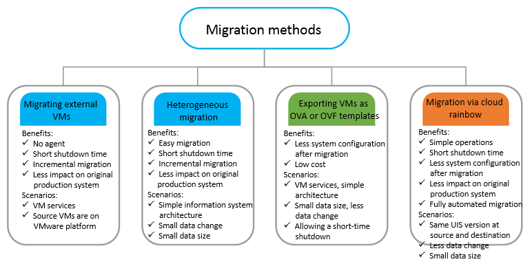
· UIS heterogeneous migration service—P2V and V2V migration, IO-level migration tool based on disk blocks
· Exporting VMs as OVA or OVF templates and importing the templates into UIS Manager as VMs—The source VMs must run on CAS CVM, UIS, VMware vSphere, Oracle VM, or ZTE iECS.
· Cloud rainbow—The source and destination must be UIS Managers of the same version.
To avoid VM startup failure caused by inconsistent AsiaInfo version, you must disable AsiaInfo anti-virus before migration.
Assessing data volume and time required for migration
For a server that runs the Windows or Linux operating system, the data volume for migration is the used disk space. If the business system to be migrated uses NAS storage, for example, NFS or CIFS, the UIS heterogeneous migration service can migrate only local disks. For NAS storage data, you can use the following methods to assess the data volume:
· If you use the UIS-NAS service or set up an NFS/CIFS file system and copy the data to UIS, the data to be migrated is the sum of the data on the local disks and data on the NAS storage device.
· If you choose to mount the NAS storage to the business system, the data to be migrated is only the data on the local disks.
Data migration in the UIS heterogeneous migration service proceeds as follows:
1. Reads source disk [source disk block I/O]
2. Processes data [source CPU and memory]
3. Sends and receives data [source NIC, network bandwidth, destination NIC]
4. Processes data [destination CPU and memory]
5. Writes data [destination disk block I/O]
The migration speed depends on the software and hardware performance at each phase of migration. In a lab environment with a GE bandwidth, the migration speed for a Linux system and a Windows system is about 80 to 90 MBps and 50 to 70 MBps, respectively. For example, migrating 60GB data takes about 15 minutes.
In most cases, the migration speed depends on the I/O read and write speed of the source and destination disks. Therefore, you can use a third-party tool to test the disk I/O performance. As a best practice, use IOMeter with the following settings: 64k block, 1worker, and sequential read/write mode.
As shown in the following table, the
service interruption time depends on the migration method.
|
Migration method |
Service interruption |
|
UIS heterogeneous offline migration |
The source server is always in shutdown state and services are interrupted until migration is finished and VMs are started. |
|
UIS heterogeneous online migration |
The source server is always in running state and services are uninterrupted during the migration process. |
|
Exporting VMs as OVA or OVF templates |
The source server is always in shutdown state and services are interrupted until migration is finished and VMs are started. |
|
Migrating a VM through the cloud rainbow feature in UIS Manager |
For a successful migration of a VM whose disks are on an NFS storage pool and uses None or Directsync caching mode, shut down the VM before the migration. |
|
Migrating a VMware VM from the CLI |
The source server is always in shutdown state and services are interrupted until migration is finished and VMs are started. |
VMware VM migration guide
The system enables you to incorporate clusters and VMs on the VMware platform. You can migrate the VMware VMs into the system. The migration does not require any agent tools, and you can complete the migration at one click with little service interruption time.
Prerequisites
The configuration examples were created and verified in a lab environment, and all the devices were started with the factory default configuration. When you are working on a live network, make sure you understand the potential impact of all configuration on your network.
· As a best practice, connect the H3C UIS Manager and VMware vCenter platform through 10GE link aggregation or bare optical fibers and make sure they are reachable to each other at Layer 3.
· Make sure the VMware VMs do not use any independent-persistent or independent-nonpersistent disks.
· To migrate VMware VMs while they are online, make sure VMware tools is installed on the VMs.
· Upgrade VMware ESXi to ESXi 6.0 3247720 or later before you migrate its VMs to UIS when the following conditions are met:
¡ The VMware version is VMware ESXi 5.5 or later, or a version between VMware ESXi 6.0 2494585 and 3247720. Data loss might occur during VM migration..
¡ The VMware version is a version earlier than VMware ESXi 6.0 and disk expansion has been performed. Data loss or migration failure might occur.
· Make sure the hardware version of the VMware VMs is 7 or higher.
· Make sure the VMware vCenter version is vSphere 6.0, vSphere 6.5, vSphere 6.7, or vSphere 7.0.
· Make sure the vCenter is accessible on port 443, and the ESXi host is accessible on port 902.
· Make sure the VMware VMs do not use SR-IOV passthrough NICs.
· A VMware VM cannot be migrated to UIS if it uses an RDM disk in physical compatibility mode. A VMware VM can be migrated to UIS if it uses NFS or uses an RDM disk in virtual compatibility mode. A VMware VM that uses a VMFS disk can be migrated to UIS, regardless of whether the storage resources are provided by SAN, iSCSI, or a local disk.
· A VM in VMware vCenter 6.0 cannot be migrated to UIS if that VM uses NFS. To migrate such a VM to UIS, you must first change its storage to VMFS on VMware.
Restrictions and guidelines
· A temporary service interruption will occur at the end of the online migration process for a VMware VM. You must start the VM and configure required parameters on UIS Manager.
· For online VMware VM migration, if the IP address of a VM is a static IP address, the IP address keeps unchanged during the migration process. If the IP address is a DHCP-assigned IP address, the IP address is assigned by the DHCP address pool.
· You must configure a network IP address for a VMware VM after that VM is migrated to UIS.
· A VMware VM cannot be migrated to an ARM host.
· To avoid migration failure, make sure the destination storage pool has sufficient space.
· You cannot migrate VMs to an RBD storage pool.
· You must configure a network IP address for a VMware VM after that VM is migrated to UIS.
· When a VMware VM is in sleep mode, its VMware tools stops running and the VM cannot be shut down automatically, which might cause migration failure or data loss. Therefore, do not set a VMware VM to auto sleep or energy saving mode during the migration.
· To avoid migration failure, do not operate a VM on VMware while the VM is being migrated to UIS.
· If a large amount of data is written to the system during the migration process of a VM, VM migration might fail because of new and original data combination timeout. This practice does not affect services. Do not write a large amount of data to the disks on the source VM during the migration process. You can shut down the VM and perform an offline migration.
· If an exception occurs on the source host of a VMware VM, migration will fail.
· For operating system compatibility, see H3C UIS Software and Hardware Compatibility Matrix.
¡ You cannot migrate VMs that use an SUSE operating system.
¡ By default, a VMware VM that uses the Windows server 2003 or Windows XP operating system uses the IDE disk bus type after it is migrated to UIS. After the migration, you must manually install CAStools. To migrate a VMware VM that uses the Windows server 2003 or Windows XP operating system, make sure the number of disks on the VM does not exceed four (including floppy drives and optical drives).
¡ After a VMware VM that uses the Windows Server 2008 operating system is started (automatically or manually) for the first time after it is migrated to UIS, you must restart the VM to have the drivers run correctly.
¡ If you migrate a VM that uses a Redhat 4 or CentOS 4 operating system (with kernel version 2.6.9-89.EL) or an earlier version, CASTools cannot be installed automatically, and you must manually install it.
¡ The console for an external VM that uses some type of operating system, for example, CentOS 7.6 might be unavailable after migration if the boot mode for that VM is UEFI. In this case, change the graphics card model to Qx1 by editing the VM, and then restart the VM.
· By default, a VMware VM uses the thin provisioning mode after it is migrated to UIS.
· After a VMware VM is incorporated into UIS Manager, do not perform lifecycle management for the VM, or start, shut down, or restart the physical host where the VM resides. If you perform these operations, the system will prompt system error.
· Only vSphere 6.7 and later versions support the simple migration method.
Configuration environment
Server
The following information applies to the
H3C UIS system. Procedures and information in the examples might be slightly
different depending on the software or hardware version of the H3C servers. The
following table shows the server models and the configuration used in this document.
This information is not an obligatory or recommended configuration for actual
deployment of the server. You can complete the configuration as long as your
server is compatible with UIS Manager.
|
Item |
Description |
|
Server #1 (VMware vCenter resources) |
H3C UIS R590 G2 · CPU: Four 10-core CPUs, Intel Xeon E5-4627 v3@ 2.60GHz · Memory: 256 GB For compatibility with other servers, see VMware Compatibility Guide. |
|
Server #2 (VMware ESXi virtualization kernel system) |
|
|
Server #3 H3C UIS Manager |
UIS-Cell 3030 G3 · CPU: 2*24*2-core, Intel (R) Xeon(R) 8260 CPU@ 2.40GHz · Memory: 256 GB |
|
Server #4 H3C UIS Manager |
UIS-Cell 3030 G3 · CPU: 2*24*2-core, Intel (R) Xeon(R) 8260 CPU@ 2.40GHz · Memory: 256 GB |
|
Server #5 H3C UIS Manager |
UIS-Cell 3030 G3 · CPU: 2*24*2-core, Intel (R) Xeon(R) 8260 CPU@ 2.40GHz · Memory: 256 GB |
Software
|
Software |
Version |
|
UIS Manager |
H3CUIS-E0742P05 |
|
VMware Server virtualization management software |
Internal version 14406112 of version 7.0.0 (6.0, 6.5, and 6.7 are also supported) |
|
Guest OS |
Windows Server 2012 64-bit |
Procedure
Network topology
Figure 4 VMware VM migration logical topology
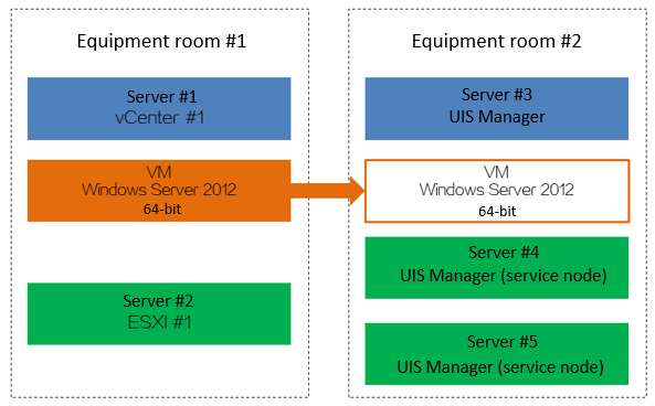
Creating a VM
1. Log in to the VMware vCenter resource (server #1) at equipment room # 1 and create a VM on server #2 (ESXi #1). The configuration for the VM is as shown in the following table.
|
Resource |
Size |
|
CPU |
One 2-core CPU |
|
Memory |
4GB |
|
Disk size |
20 GB (shared storage) |
|
Disk provisioning |
Thin provisioning |
|
Disk mode |
Default |
|
Network adapter |
1*E1000 |
|
MAC address |
Default (automatic) |
|
|
IMPORTANT: The configuration in the table is only for a test environment. It is not a recommended configuration in a production environment. In a production environment, determine the VM configuration based on the CPU, memory, disk, and NIC requirements for your business system. |
2. Mount the Windows Server 2012 64-bit operating system CD image for the VM through CD/DVD drive 1.
3. Start the VM and install a guest OS for the VM.
4. Mount and install the VMware Tools for the VM.
|
|
IMPORTANT: Configure custom settings such as disk partitioning, admin account configuration, and component installation based on your requirements in the production environment. |
Migrating VMware VMs
(Optional.) Enabling vSphere backup NFC
You can configure a migration IP address when you incorporate an external cluster. Migration IP address configuration is available only for VMware vSphere 7.0 and later versions and vSphere backup NFC must be enabled. If you do not specify a migration IP address, you do need to enable vSphere Backup NFC.
To enable vSphere backup NFC:
1. Log in to VMware vCenter.
2. Create a VMkernel adapter, and enable vSphere Backup VFC for the adapter.
Adding a VMware cluster to UIS
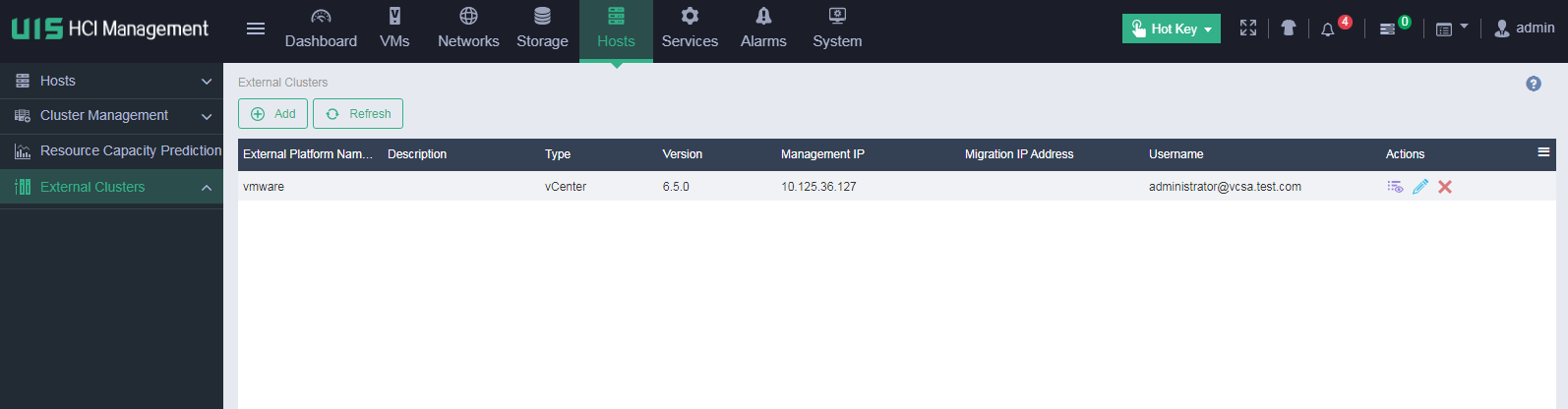
1. On the top navigation bar, click Hosts, and then select External Clusters from the left navigation pane.
Figure 5 Adding a VMware cluster to UIS
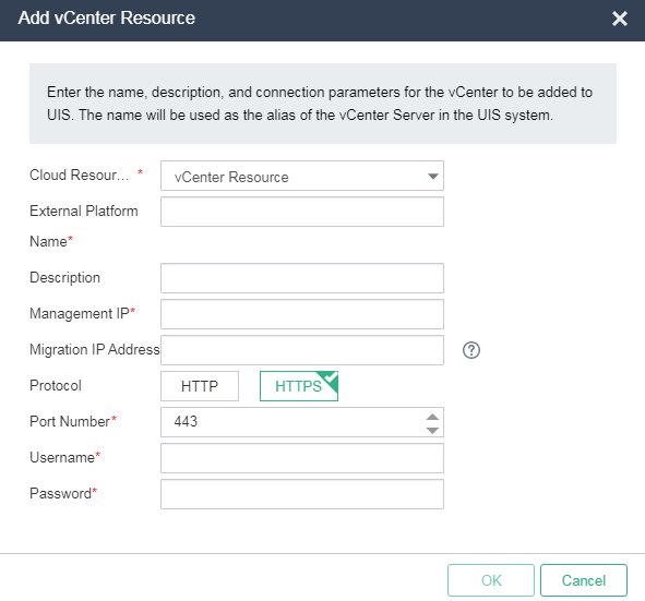
2. Click Add. Configure the parameters and then click OK.
Figure 6 Adding a VMware vCenter resource to UIS
|
Parameter |
Description |
|
Cloud Resource Type |
Required. Select an external cluster type. In the current software version, only VMware vCenter resources are supported. |
|
Resource Name |
Required. Enter a name for the external cluster. This name will be displayed in the external cluster list on UIS. |
|
Description |
Optional. Enter a description for the external cluster. A maximum of 128 characters are supported. |
|
Management IP |
Required. Enter the management IPv4 address of the external cluster. |
|
Migration IP Address |
Optional. Specify the migration network IP address. This parameter is available for only VMware vSphere 7.0 and later versions. The migration IP address, the vCenter, and the ESXi host's NIC configured with tag vSphere Backup NFC must be reachable to each other. For more information, see the VMware documentation. The vSwitch used by UIS is determined by the migration IP address, the vCenter, and the ESXi host's NIC. |
|
Protocol |
Required. Select the protocol that is used to access the external cluster. Options include HTTP and HTTPS. |
|
Port Number |
Required. Enter the port number that is used to access the external cluster. The default port number is 80 for HTTP and 443 for HTTPS. |
|
Username |
Required. Enter the username that is used to access the external cluster. The maximum length is 128. |
|
Password |
Required. Enter the password that is used to access the external cluster. The maximum length is 128. |
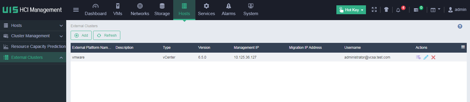
Figure 7 Newly added VMware vCenter resource
Migrating an online VM
For more information about the parameters, see the online help.
To migrate an online VM:
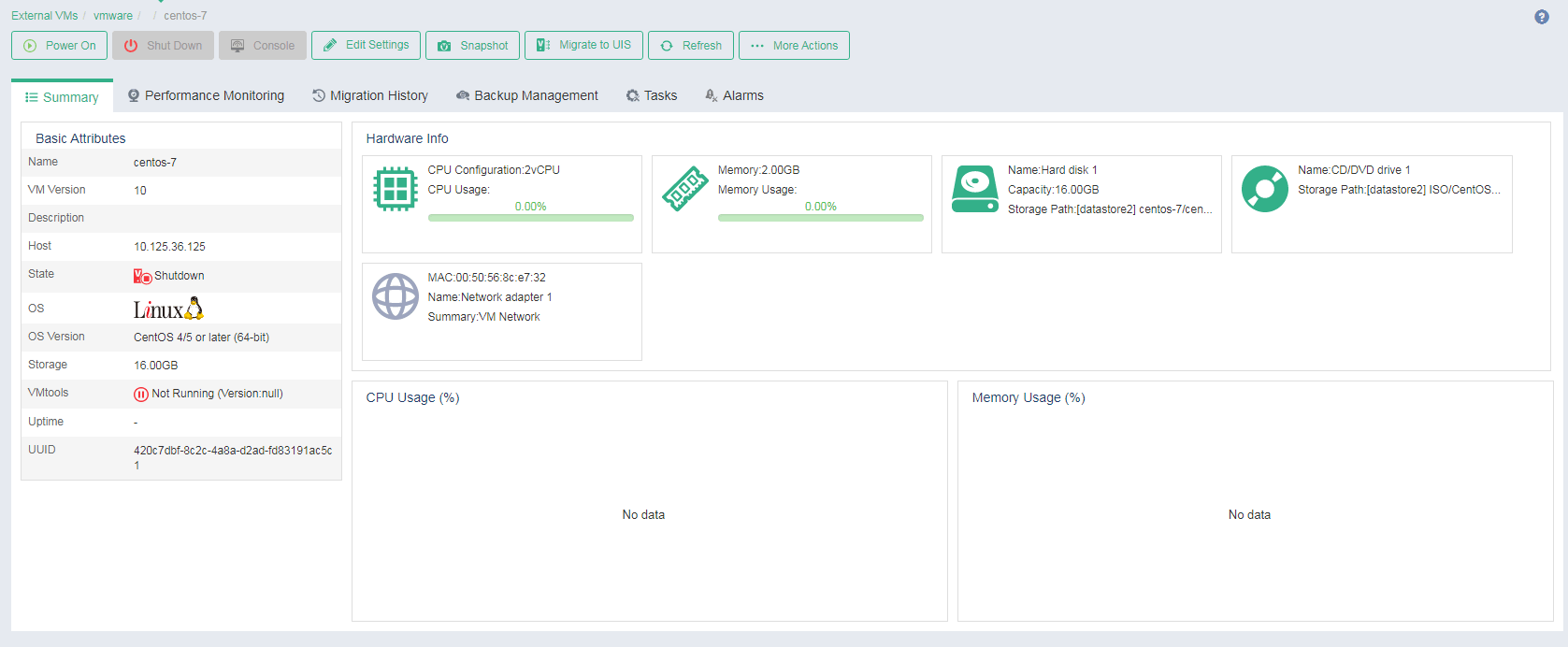
1. On the top navigation bar, click VMs.
2. From the left navigation pane, select External VMs > vCenter Site Name > Cluster Name.
3. Click the name of the target VM.
Figure 8 External VM details
4. Click Migrate.
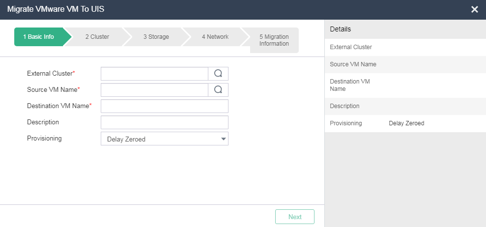
5. Configure basic information for the VM, and then click Next.
Figure 9 Configuring basic settings for the VM
6. Select the target host, and configure storage and network information for the VM. Please select an appropriate host for the VM based on the CPU and memory usage of the target host.
Figure 10 Selecting a host
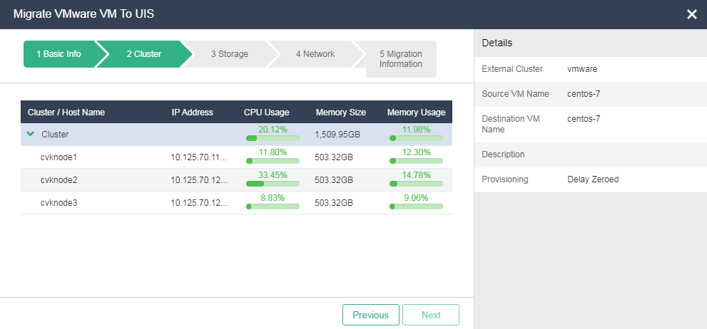
Figure 11 Configuring storage settings for the VM
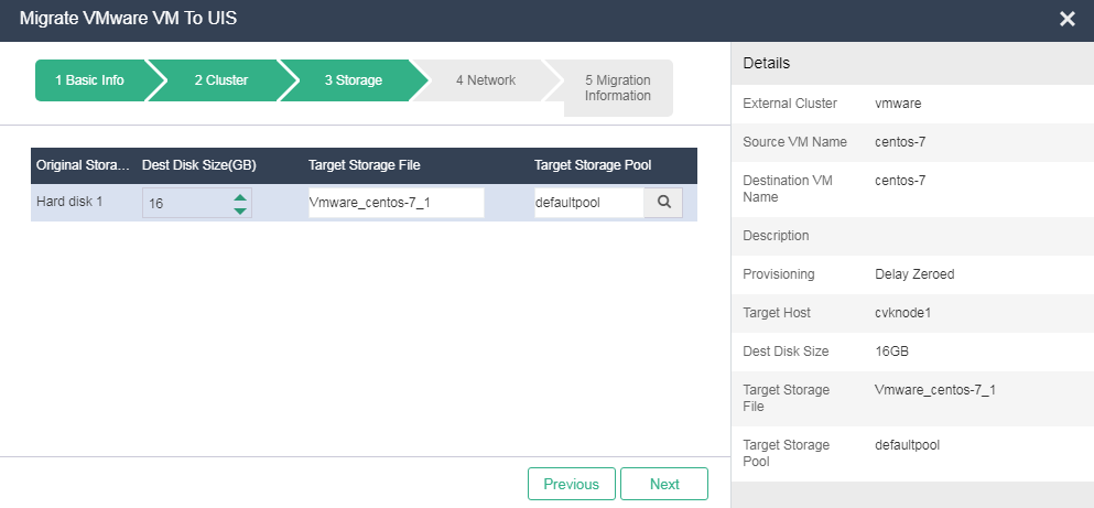
Figure 12 Configuring network settings for the VM

7. Configure migration task information.
Figure 13 Migration information
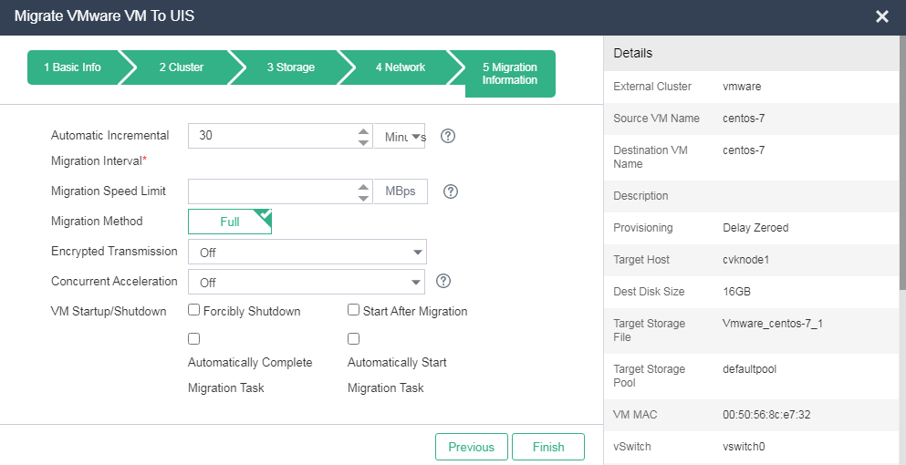
8. Click Finish.
9. On the top navigation bar, click Hosts, and then select External Clusters > Migration Tasks from the left navigation pane.
Figure 14 Migration task
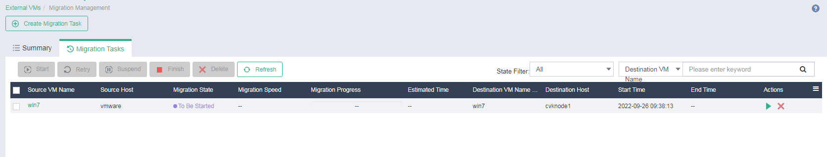
10. Click the Migration Tasks tab.
Click the ![]() icon for a migration task. Alternatively, click a migration task
name, and then click Start.
icon for a migration task. Alternatively, click a migration task
name, and then click Start.
Figure 15 Starting the migration task
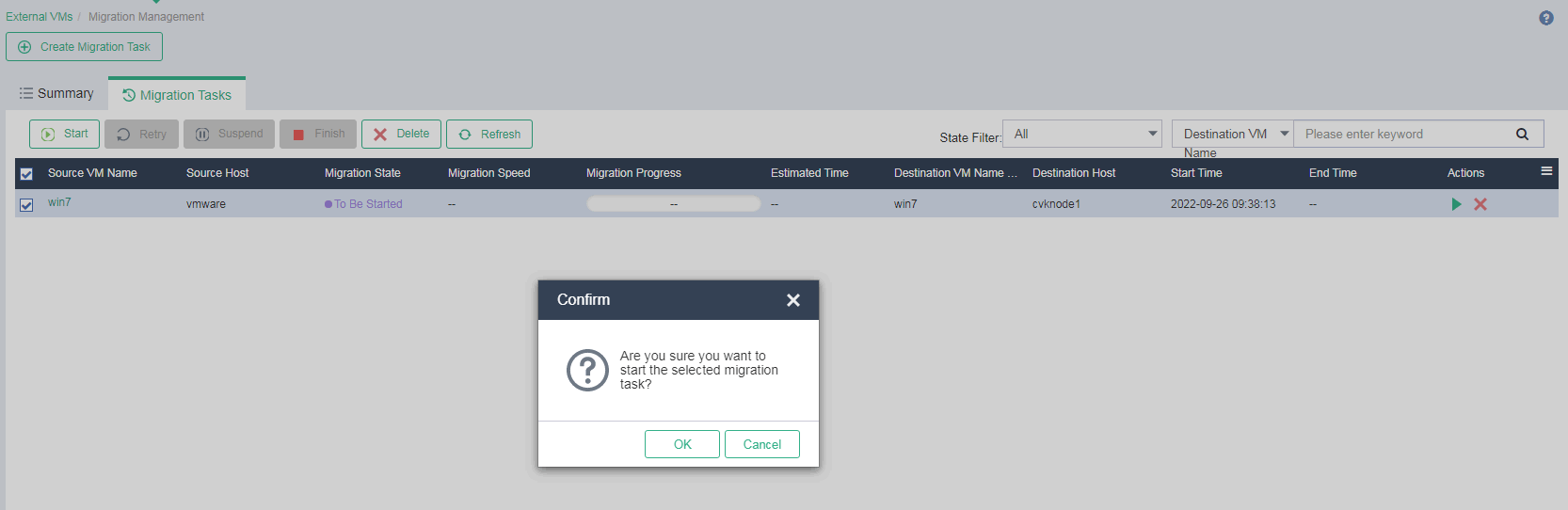
11. Click OK.
12. Click the ![]() icon for a
migration task in Migrating (To Be Completed) state, and then click OK.
Alternatively, click the name of a migration task in Migrating (To Be
Completed) state, and then click Finish.
icon for a
migration task in Migrating (To Be Completed) state, and then click OK.
Alternatively, click the name of a migration task in Migrating (To Be
Completed) state, and then click Finish.
Verifying the migration result
1. Verify that the task console displays the migration progress, and the migrated VM is running correctly on the destination host.
Figure 16 Viewing the VM status on the destination host
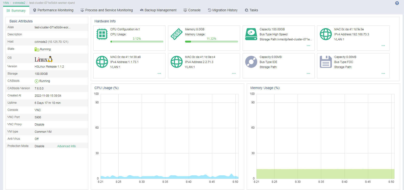
2. Verify that the operating system and disk information are the same as those before the migration.
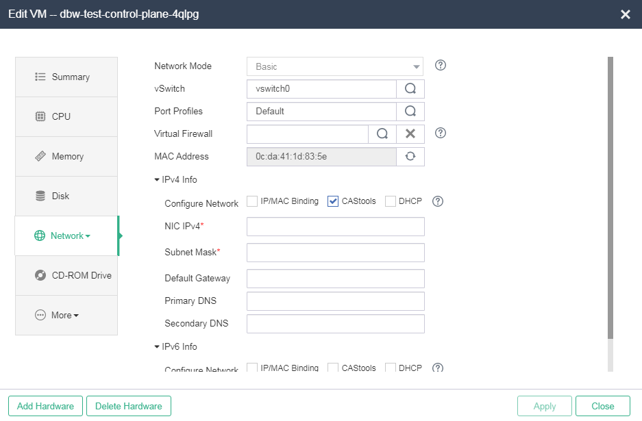
3. Click Edit.
4. Click the Network tab, select CAStools, and then enter the IP address of the VM. If CAStools is not installed correctly on the VM, first install CAStools for the VM.
Figure 17 Specifying an IP address
Troubleshooting VMware VM migration
To troubleshoot VMware VM migration issues, perform the following steps:
1. Verify that the following services are in active state:
¡ UIS management node—vmware-api-server
¡ UIS service host—vmware-agent
2. Check the connection state between UIS Manager and VMware vCenter.
¡ Identify whether the UIS management node can connect to VMware vCenter through the IP address and port number specified in incorporating VMware VMs.
¡ Identify whether the destination host can connect to VMware vCenter through the management/migration IP address and port number specified in incorporating VMware VMs. Identify whether the destination host can connect to port 902 on the source ESXi host for migration.
3. Check the connection state between VMware vCenter and ESXi hosts.
¡ Identify whether VMware vCenter can connect to port 902 on the source ESXi host for migration.
¡ Identify whether a domain name is used when VMware vCenter incorporates ESXi hosts. If a domain name used, you must configure DNS on the UIS host.
4. Identify whether the issues in this section can cover all issues during migration.
5. View log files to identify issues.
For example, if a migration issue has occurred and the vddk log file prompts an error, you can try to obtain the solution in the VMware KB based on the error code.
Table 6 Log files
|
Log file |
Remarks |
|
/var/log/uis-core/uis.log |
UIS frontend service log file, which is used for initial issue location. |
|
/var/log/vmware-api-server/vmware-api-server-{date}.log |
API service log file related to VMware VM incorporation and migration. It is used for locating VMware VM lifecycle management issues and initial location of VMware VM migration issues. |
|
/var/log/vmware-agent/vmware-agent.log |
Migration service log file. You can view the ERROR logs for fast location of migration issues. |
|
/var/log/vmware-agent/vmware_vddk.log |
VDDK service log file. If a migration task cannot start or the system prompts an error during the migration process, you can use this log file for issue location. |
|
/var/log/xconvertor.log |
Format conversion log file. Typically, no format conversion errors will occur. |
|
/var/log/caslog/cas_xs_virtio_driver.log |
Driver injection log file. If UIS frontend prompts a driver injection failure, you can use this log file to locate the issue. |
All known issues are caused by VMware platform bugs. For the issue described in 2.5.1, see Resetting Changed Block Tracking for VMware vSphere virtual machines (2139574) at the VMware official website. For the issue described in 2.5.3, see Unable to take a quiesced VMware snapshot of a virtual machine (1009073) at the VMware official website. For the issue described in 2.5.4, see How to disable application level quiescing during snapshots of virtual machines (2146204) at the VMware official website.
Migration of a VM fails after the snapshot for that VM is deleted
Symptom
Migration of a VM fails after the snapshot for that VM is deleted.
Reason
This issue is caused by CBT. You must reset CBT on the VM. The virtual disks to be migrated must be on VMFS volumes provided by SAN, iSCSI, or local disks. When CBT is enabled, a VM can be cleared and started only if it does not have snapshots. Therefore, VMware VMs can be migrated after the snapshots are deleted. To migrate VMs that have snapshots in vCenter 6.0, see the solution before migrating the VMs.
Solution
To reset CBT on a VM:
1. Open the vSphere Web Client.
2. Right-click the VM and then click Power Off.
3. Right-click the VM, click the Snapshot and navigate to Snapshot Manager. Ensure there are no active snapshots. If there are snapshots present, consolidate them to commit the changes.
4. Right-click the VM, and then click Edit settings.
5. Navigate to Advanced > General > Configuration Parameters.
6. Disable CBT for the VM by setting the value for ctkEnabled to false.
7. Disable CBT for the individual virtual disks attached to the VM by setting the scsix:x.ctkEnabled value for each attached virtual disk to false. scsix:x is SCSI controller and SCSI device ID of your virtual disk.
8. Open the VM's working directory by using the Datastore Browser or ESXi shell.
9. Ensure there are no snapshot files (.delta.vmdk) present in the VM's working directory.
10. Delete any -CTK.VMDK files within the VM's working directory.
11. In the vSphere Client, right-click the VM and click Power On.
|
|
CAUTION: If you are using a backup application that uses CBT, you must re-enable CBT manually. |
To reset CBT on multiple vSphere VMs using a PowerCLI script:
1. Download the 2139574_CBT-Reset.zip file attached to this article.
2. Extract the CBT-Reset.PS1 file from the archive and save.
3. Install and initialize VMware PowerCLI on your local system.
4. Open VMware PowerCLI.
5. Change directory to where you saved the CBT-Reset.PS1 file by running the cd command: For example: PowerCLI C:\> cd C:\CBTreset
6. Allow execution of an unsigned script by running this command: PowerCLI C:\CBTreset> Set-ExecutionPolicy Bypass
|
|
WARNING! This allows any unsigned script to run. Ensure you disable it after use. |
7. Connect to your vCenter Server using this command: PowerCLI C:\CBTreset> Connect-VIServer -Server vcenter -User username -Password password
vcenter is the name of your vCenter Server, username is your vCenter Server username, and password is your vCenter Server user password.
8. Run this command to load the CBT-Reset.PS1 script: \CBT-Reset.PS1
|
|
CAUTION: If you receive an error similar to File .\CBT-Reset.PS1 cannot be loaded because the execution of scripts is disabled on this system, check step 6 is applied correctly. |
9. The script provides a report of VMs that are applicable. The script lists both VMs where CBT can be reset and cannot be reset.
¡ All VMs where CBT can be reset are listed.
¡ All VMs where CBT cannot be reset (VMs that are powered off or have snapshots) are listed for notification purposes.
|
|
CAUTION: When the script runs, a temporary VM snapshot is taken. This avoids the needs for a power cycle of the VM. |
10. The script prompts you to confirm execution and proceed with the CBT reset of applicable VMs.
11. If you choose to continue, CBT data is reset for the VMs that do not have snapshots and the power state is on.
Failed to add an external cluster to UIS Manager
Symptom
The system prompts invalid username or password and cannot add an external cluster.
Reason
VMware does not limit the username and password length. However, UIS limits the username and password length when an external cluster is added.
Solution
To resolve this issue:
1. Log in to the vSphere Web Client by using the original administrator account.
2. Click Home, and browse to Administration > Single Sign-On > Users and Groups.
3. Select a correct domain. On the Users tab, click Add.
4. Type a username and password for the new user. Make sure the username and password length meets the requirements.
5. Click Administration and select Global Permissions in the Access Control area.
6. Click Manage, and click the Add
permission icon ![]() .
.
7. Select a domain and the newly added user, select the administrator role, and then select Propagate to children.
8. Click OK.
9. Log out of vSphere Web Client, and log in by using the new account.
10. If the account is valid, you can add the VMware cluster to UIS by using this account.
The system prompts snapshot deletion failure and the migration fails
Symptom
VMware VM migration fails, and UIS Manager prompts snapshot deletion failure and VMware prompts snapshot saving and VM quiescence failures.
Reason
The VMware VM cannot be quiesced during migration.
Solution
To resolve the issue, quiesce the VM as instructed in the official website of VMware, and then continue the migration. For more information, see Unable to take a quiesced VMware snapshot of a virtual machine (1009073).
The task cannot start and the system stays in migrating storage state if a VM that uses the Windows Server 2008, 2012, 2016, or 2019 operating system is migrated
Symptom
The migration task cannot start and the system remains in migrating storage state if a VM that uses the Windows Server 2008, 2012, 2016, or 2019 operating system is migrated.
Reason
The VM uses a VSS-based quiesced snapshot.
Solution
To resolve the issue:
1. Use vSphere Client to disable application level quiescing during snapshots of virtual machines.
2. Log in to the vCenter Server or ESXi host from the vSphere Client.
3. Shut down the VM.
4. Right-client the VM, and then click Edit settings.
5. Navigate to Advanced > General > Configuration Parameters.
6. Add or modify the row: disk.EnableUUID with the value FALSE.
7. Click OK to save the configuration.
8. Click OK to exit.
9. Start the VM.
10. If the issue persists, you might need to unregister/reregister the VM from the vCenter inventory.
11. Power off the VM.
12. Notate the VM's datastore directory path to the .vmx file.
13. Right-click the VM.
14. Click Remove from Inventory.
15. Reregister the VM back to the inventory by navigating to the VM's datastore folder, right-click on the .vmx file, and register
16. Disable VSS application quiescing using the VMware Tools configuration:
17. Open the file C:\ProgramData\VMware\VMware Tools\Tools.conf file using a text editor.
18. If the file does not exist at the location mentioned above, create it.
19. Add these entries to the file:
[vmbackup]
vss.disableAppQuiescing=true
20. Save and close the file.
21. Restart the VMware Tools Service.
a. Click Start > Run, type services.msc, and click OK.
b. Right-click the VMware Tools Service and click Restart.
Heterogeneous migration configuration guide
About heterogeneous migration
Heterogeneous migration allows migration of disk data on physical x86 servers, VMs managed by UIS Manager, and VMs managed by another platform to destination VMs on the UIS Manager platform. It requires client installation on the source device.
Restrictions and guidelines
· For incremental migration or incremental backup, the maximum capacity of a volume or disk cannot be greater than 128 TB. A higher hot migration performance can be achieved if the capacity is lower than 32 TB. The data volume change can only be smaller than 1 TB within the incremental migration or backup interval.
· Make sure the capacity of each file system is less than 64 TB if you perform a simple migration for an EXT2/EXT3/EXT4 file system.
· A license is required for heterogeneous migration. Before you can use this feature, you must request a license. For more information, see H3C UIS Manager Local Licensing Guide-5W100.
¡ The migration license will become invalid after reinstallation of UIS Manager. You must download hardware codes and request for a new license.
¡ In the dual-node scenario, if a heterogeneous migration license is registered on the master node, you cannot perform a migration after a master/backup switchover. To perform a migration, you must use the original master node as the management node.
· In the dual-node scenario, you can use only the IP address of the master node as the migration IP. You cannot use a VIP as the migration IP.
· You can use a trial license for only 30 days. When the trial license expires, you must renew the license.
· If the source device is deleted when a migration task is being executed, the migration task will fail. However, the task cannot be deleted from UIS Manager. You must re-create the source device to continue the migration task or contact Technical Support to delete the task from UIS Manager.
· For more restrictions and guidelines, see the usage guide for the compatible version or contact Technical Support.
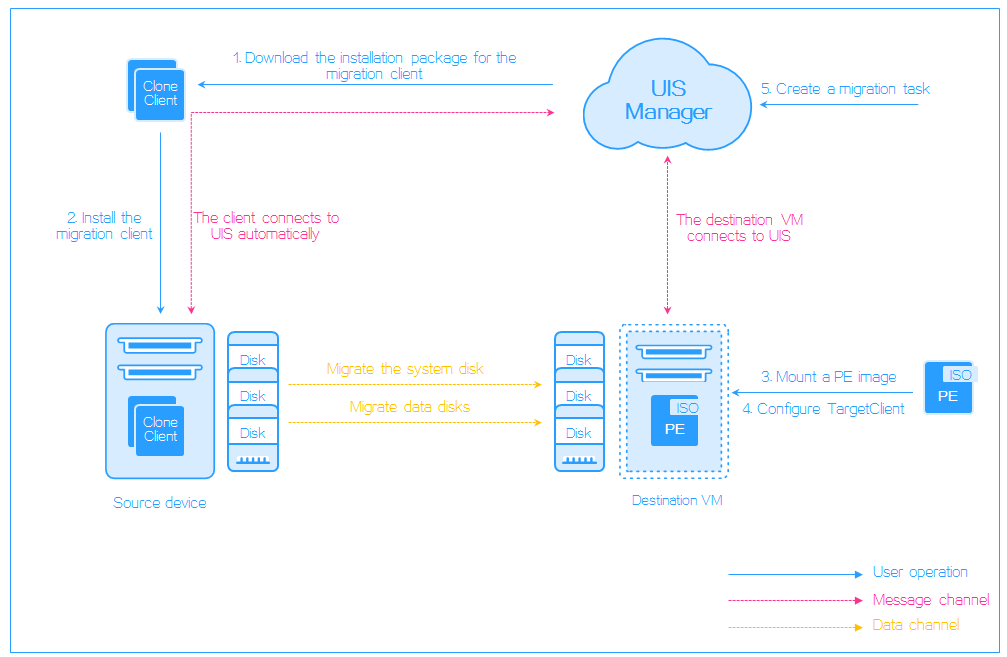
Migration workflow
To perform a heterogeneous migration, you must perform the following tasks:
1. Install the heterogeneous migration component.
2. Apply for the migration license.
3. Download a migration client from UIS Manager to a source device (physical server or VM).
4. Install the migration client and connect the source device to UIS Manager. Then, the migration client reports the status of the source device to UIS Manager.
5. Mount the PE image to the destination VM, configure the TargetClient, and connect TargetClient to the UIS Manager. Then, the TargetClient reports the status of the destination VM to UIS Manager.
6. Create and start a migration task. The migration client receives the migration command and starts migrating the system disk and data disk.
Figure 18 Heterogeneous migration
Procedure
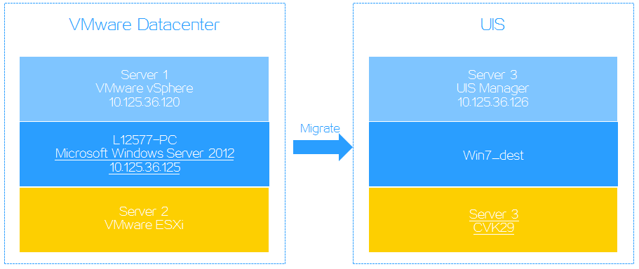
Configuration requirements
This document uses an environment shown in Figure 19 as an example.
Figure 19 Migration environment
Installing the heterogeneous migration component
1. Upgrade the movesure.tar.gz package to any folder on the target host.
2. Execute the tar –zxvf movesure.tar.gz command to decompress the package to the current folder.
3. Execute the sh install_en.sh command in the movesure folder to install the heterogeneous migration component.
|
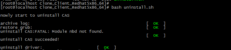
|
IMPORTANT: To uninstall the heterogeneous migration component, execute the sh uninstall.sh command. |
Preparing a source device
Downloading an installation package
1. Log in to UIS Manager.
2. On the top navigation bar, click Services.
3. From the left navigation pane, select Heterogeneous Migration.
4. Click the Download Client tab.
5. Verify that the client proxy IP address is correct. By default, the client proxy IP address is the management IP address of UIS Manager.
If the IP address is different from the actual address, click Update Client Proxy IP, which is available only after the migration license is activated.
6. Use the following methods to download the target installation package:
¡ Click the target OS name. The system downloads the installation package in a .zip file named Clone_Client_xxx.zip, for example, Clone_Client_Redhat5x86_64.zip. Then, you must decompress the file and upload the decompressed installation package to the source device through FTP.
¡ Click
the ![]() icon
for the target client edition to obtain the URL for downloading. Then, access
the remote console of the source device and use the URL to download the
installation package.
icon
for the target client edition to obtain the URL for downloading. Then, access
the remote console of the source device and use the URL to download the
installation package.
Figure 20 Downloading a migration client

Installing the migration client
|
|
IMPORTANT: To avoid installation failure, disable firewall and security policy settings for the source device. If the source device is a VM, make sure the ports for migration tools (4301, 4302, 4305, 9980, and 9981) have been enabled on the source device. |
This section describes installing the migration client on a Windows OS. For more information about installation on a Linux OS, see "Installing a migration client on a Linux OS"
To install the migration client:
1. Access the remote console of the source device.
Figure 21 Accessing the remote console of the source device
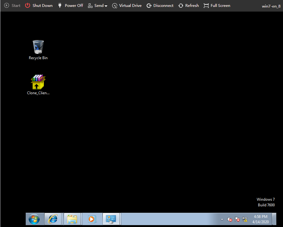
2. Double-click Clone_Client_Win.exe.
3. In the window that opens, select the installation language and then click OK.
4. Accept the installation agreement, select the installation directory, and start the installation process.
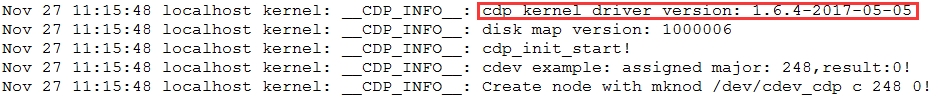
5. Click Y at the prompt to install the CDP driver program.
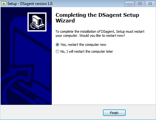
6. After the installation, restart the source device for the installed client to take effect.
|
|
CAUTION: The restart operation will interrupt services if the source device uses a Windows operating system. Restart the source device when it is not busy to minimize the impact. |
Figure 22 Restarting the source device
Installing a migration client on a Linux OS
1. Log in to the source device to view the kernel version of the OS.
Figure 23 Viewing the kernel version of the OS

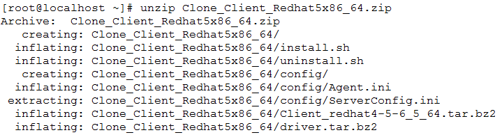
2. Execute the unzip Clone_Client_xxx.zip command to decompress the installation package.
3. Execute the ./install.sh command to run the installation script.
Figure 24 Installing the client
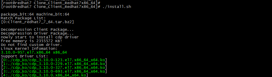
4. Select the matching driver package at the prompt and enter y.
The suffix for the kernels must be the same, for example, default, ky, and xen.
If multiple driver packages exist, select the one that has a similar version as the system kernel.
Figure 25 Selecting the kernel
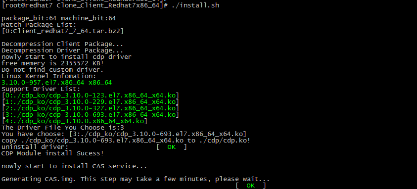
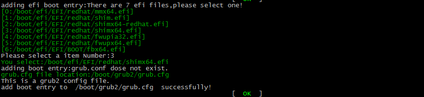
5. (Optional.) Select the EFI, if required, based on the OS information.
If the source device boots in UEFI or EFI mode, you must select the EFI firmware file.
Figure 26 Selecting the EFI
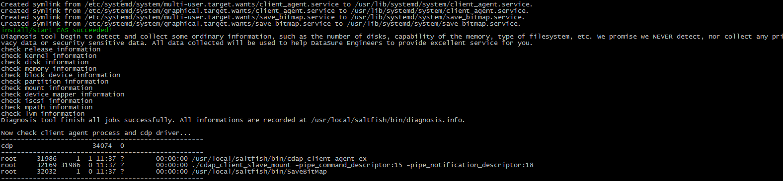
The system prompts install/start CAS succeeded! after the installation finishes.
Figure 27 Installation completion
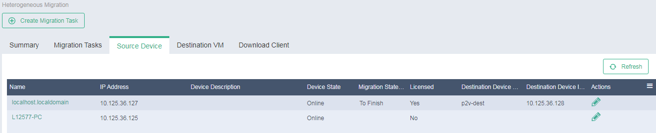
Viewing the source device
After the restart, you can access the Services > Heterogeneous Migration > Source Device page to verify that the source device has been added to the source list. By default, the system names source devices by their computer names in the operating system.
Figure 28 Source device list
Preparing a destination VM
Obtaining the PE image
UIS provides Win10PE and Centos7PE images for migration in Windows OS and Linux OS, respectively. The PE images are released with the UIS version image.
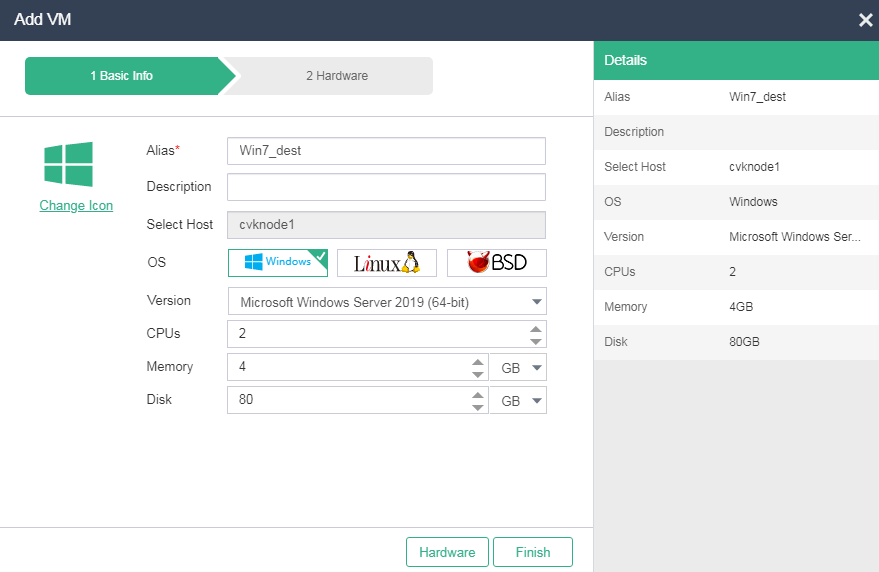
Creating a destination VM
|
|
CAUTION: If the source device uses the Suse10 OS, set the bus type to IDE when creating a destination VM. |
Create the destination VM on UIS Manager as shown in Figure 29. Make sure both the available disk size and total disk size of the destination VM are equal to or larger than the disk sizes of the source device.
Figure 29 Creating the destination VM
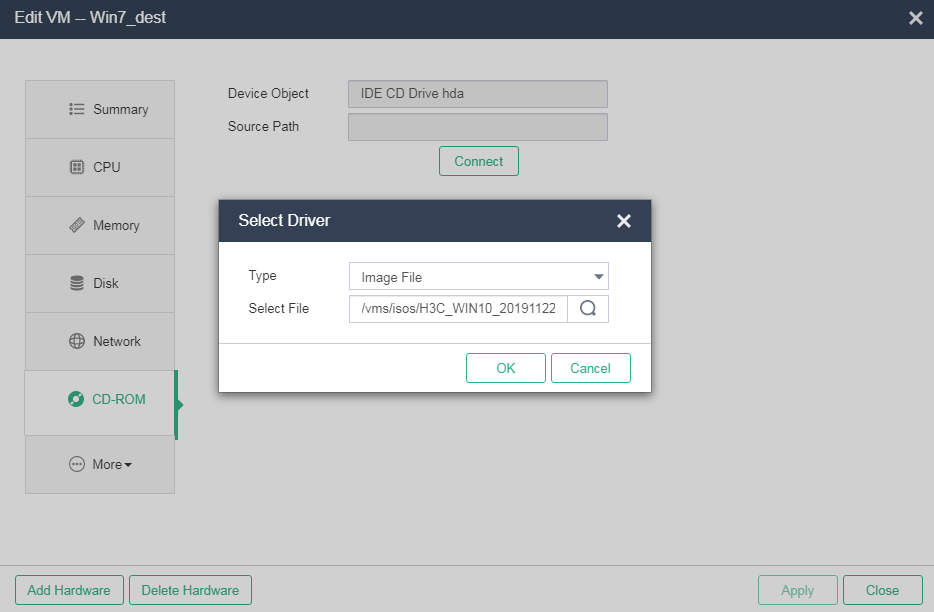
Configuring TargetClient
1. Mount the PE image to the destination VM.
Figure 30 Mounting the PE image to the destination VM
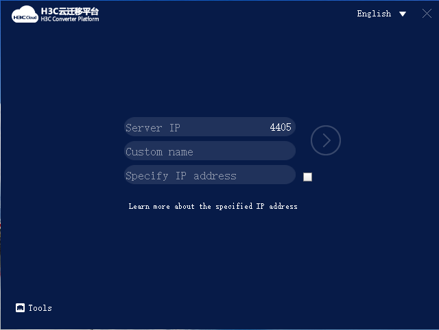
2. Start the destination VM and access the VM's console. The VM boots from the PE image and runs TargetClient to access the H3C Converter Platform.
Figure 31 H3C Converter Platform
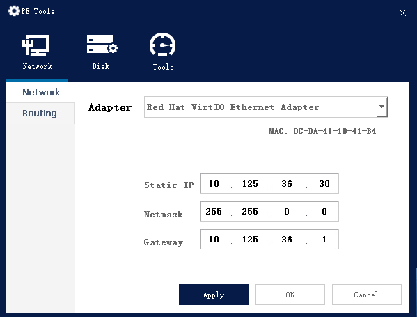
3. Click Tools and configure network settings for the VM to communicate with UIS Manager.
|
|
CAUTION: The network settings configured in this step get lost after the VM restarts. After the migration, you can reconfigure network settings for the VM as needed. |
Figure 32 Configuring network settings
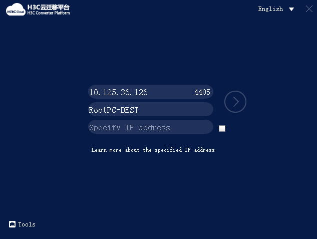
4. Enter the IP address of UIS Manager, specify a host name for the VM, and then click the chevron.
The local IP address field is optional. By default, the default IP address used by the destination VM to access the migration platform is used. If UIS Manager uses a public IP address, or if two hosts provide stateful failover, you must specify a local IP address. If you do not do so, the source device cannot connect to the destination VM.
Figure 33 Configuring TargetClient parameters
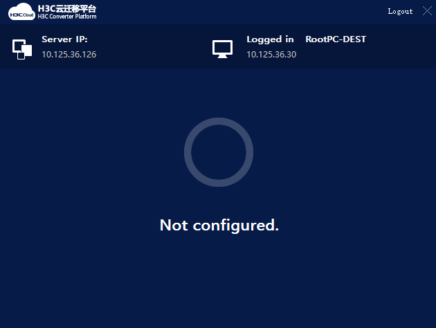
The page that opens indicates that TargetClient and the destination VM have been connected to UIS Manager.
Figure 34 TargetClient connection
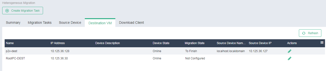
5. Access the Services > Heterogeneous Migration > Destination VM page to verify that the destination VM has been added to the destination VM page, and the VM status is online.
|
|
IMPORTANT: Only online destination VMs support migration tasks. If the migration operation fails for an online destination VM, verify that no network address conflict exists. |
Figure 35 Destination VM list
Performing a migration
Restrictions and guidelines
The migration process will occupy the network bandwidth and affect the computing performance of the source device, and services will be interrupted during migration. As a best practice, perform data migration during off-peak periods, and properly arrange the service switchover time.
To avoid migration failures or other compatibility issues, verify that the platform is compatible with the operating system of the source device and the destination device has sufficient hardware resources.
You might need to reload or update the drivers for some hardware after migration. Some hardware settings such as the MAC address of the NIC and hard drive letter might change. If there are applications bound to hardware, you must edit the applications accordingly.
Creating a migration task
1. On the top navigation bar, click Services.
2. From the left navigation pane, select Heterogeneous Migration.
3. Click Create Migration Task.
4. Select I have read the restrictions and guidelines, and then click Next.
5. Specify the source device and destination VM.
Figure 36 Specifying the source device and destination VM
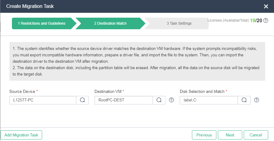
6. Select source and destination disks.
By default, the system maps each source device disk to a target device disk. If you manually map a source disk to a target disk, make sure the target disk has a same or larger size than the source disk. For dynamic source disks, the destination disks and source disks must have the same size.
|
|
IMPORTANT: · Only system disks and data disks can be migrated. · You do not need to select a destination disk for an LVM disk because it is a logical volume, but the system also migrates LVM data. · The data on the destination disk, including the partition table will be erased. After migration, all the data on the source disk will be migrated to the target disk. |
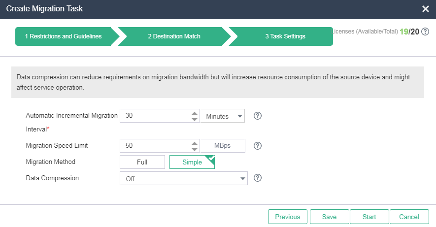
7. Configure task parameters as needed.
Figure 37 Configuring task parameters

8. To start the migration task immediately, click Start. To save the migration task, click Save. You can access the migration task list later to start a saved task.
|
|
· CAUTION: · Before you configure a migration task, you must license the source devices to be specified in the task. You can execute a migration task multiple times and specify the same source device in multiple migration tasks. · When a migration task is saved or executed, a migration license is issued to a source device immediately. An issued license cannot be reclaimed, even if the system fails to create the migration task. In such a case, locate the cause of failure and create another migration task. · Set a bandwidth limit on data transmission to guarantee enough bandwidth for services. As a best practice, set the limit to 50 MBps, set the automatic incremental migration interval to 30 minutes, and set the migration method to simple migration. Full migration copies a disk as a whole. Simple migration copies only valid data blocks of disks. · You can select whether to compress the data of the source device before transmission. Data compression saves bandwidth but consumes resources of the source device and might affect operation of the source device. ¡ Off—Does not compress data, which consumes network bandwidth. ¡ Compression Ratio First—50% data compression ratio before migration, which consumes the most CPU resources. ¡ Performance First—30% data compression ratio before migration, which consumes fewer CPU resources than the Compression Ratio First method. This method ensures performance of the source device. |
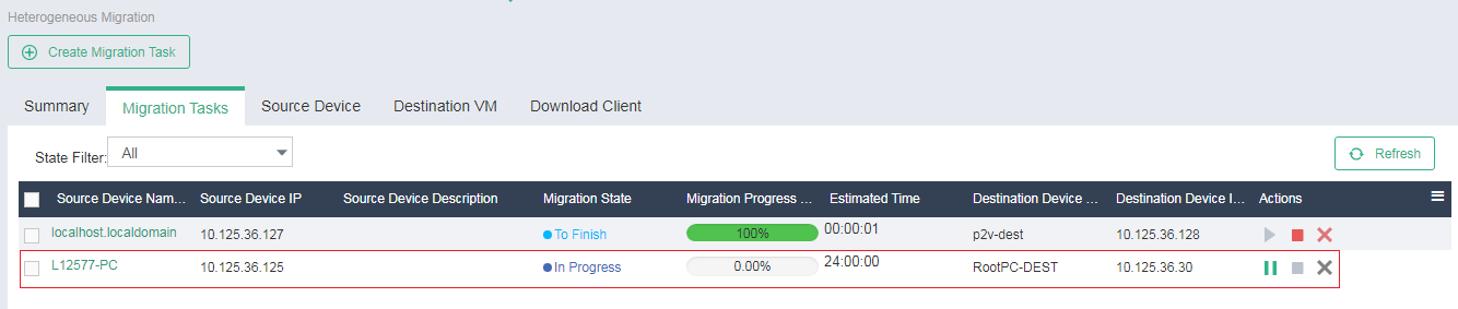
9. To view the migration task list, click the Migration Tasks tab. The system names migration tasks by source device names and updates the list every 30 seconds.
Figure 38 Migration task list
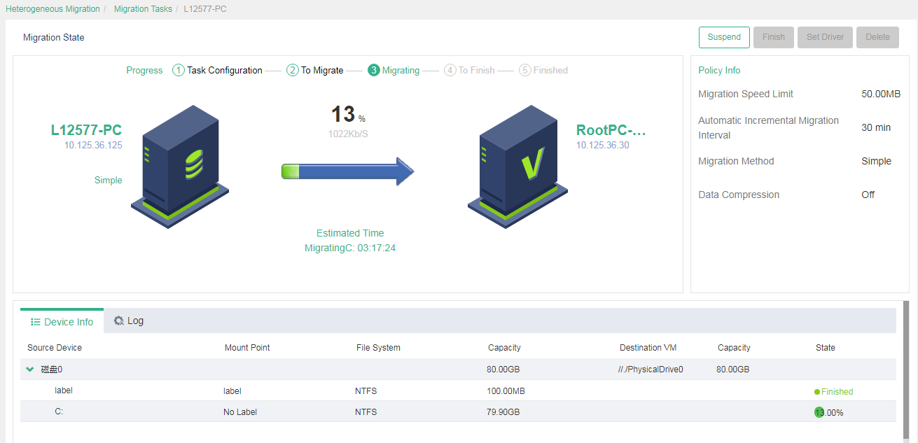
10. To view detailed information about a migration task, click the source device name. The detailed information page displays the migration process, device information, and logs.
|
|
NOTE: The system calculates the execution progress of a migration task by periodically sampling data. The system might not refresh the execution progress in real time when migrating a large number of disks, which does not affect migration. You can check the migration progress for the migration state of each disk. |
Figure 39 Viewing detailed information about a migration task
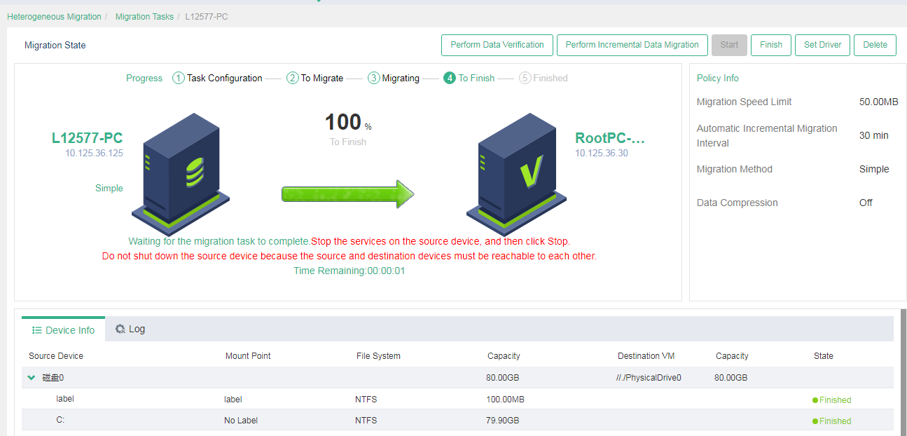
11. The system executes a migration task periodically at the incremental migration interval if you do not finish it manually. To manually finish a migration task, click Finish.
Before manually finishing a task, you must stop the services on the source device to prevent the device from generating new data.
|
|
CAUTION: You can manually perform incremental data migration for a migration task that is not finished after its first execution. Incremental migration copies only the changed or new data since the previous migration. You can verify data integrity and restore data for a migration task that is not finished after its first execution. |
Figure 40 Finishing a migration task
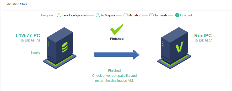
After you finish the task, the task enters Finished state.
Figure 41 Migration completion
Configuring a driver
|
|
IMPORTANT: As a best practice, for Linux OSs, use Virtio drivers if the kernel version is 2.6.25 or higher (for example, redhat 5.2), and use IDE drivers if the kernel version is not. |
The system can detect disk driver incompatibility risks for a migration task. You can export information about the hardware that might have driver incompatibility issues and import drivers for the hardware to the destination VM.
You must import drivers manually when the following conditions are met:
· The VM has blue screen or black screen issues after migration or the VM can start but some disks cannot be identified or peripherals are unavailable. The issues cannot be resolved even if the driver type is changed for the VM.
· A Windows blue screen issue or a 007B error occurs.
· The system prompts disk driver incompatibility risks. You must import the required drivers after migration to avoid startup failure of the VM.
To configure a driver:
1. On the top navigation bar, click Services.
2. From the left navigation pane, select Heterogeneous Migration.
3. Select the Migration Tasks tab.
4. Click the source device name of a migration task.
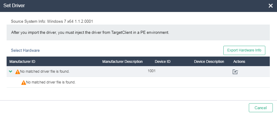
5. Click Set Driver.
Figure 42 Configuring a driver

6. Click Export Hardware Info. The system exports hardware information about disks of the destination VM in TXT format.
7. Open the downloaded file to view information about the required drivers. The file name is Destination_VM_name Driver Hardware Info.txt.
8. Compress driver files to be uploaded into a .zip file and name the compressed file mptspi.zip.
Typically, driver files are .sys or .inf files and .ko files for Windows and Linux, respectively.
Make sure the compressed file does not contain multi-layered folders.
9. On the detailed task information page, click the import button to import the compressed file to UIS Manager.
Figure 43 Importing the compressed file to UIS Manager
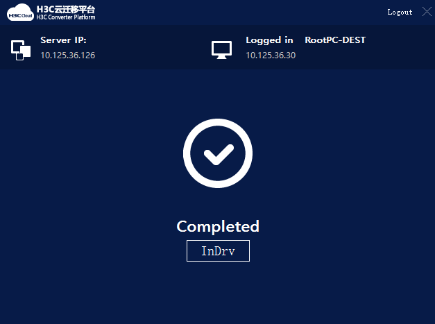
10. Click InDrv in TargetClient to install drivers to the destination VM.
Figure 44 Installing drivers
Accessing the destination VM
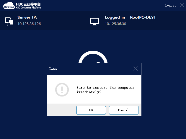
1. Access the console of the destination VM and exit the H3C Converter Platform.
2. At the prompt, click OK to restart the destination VM.
If you cannot access the VM's operating system or the system prompts partition or disk not found, power off the VM, restart the VM, and select boot from CAS.
Figure 45 Restarting the destination VM
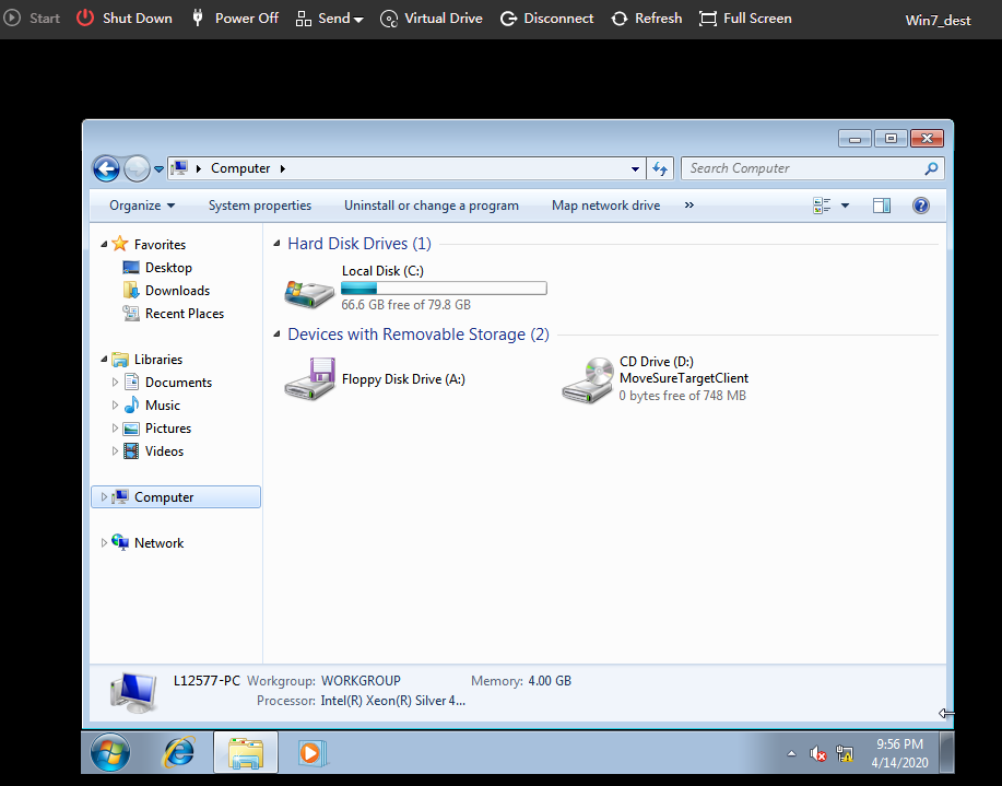
3. Enter the username and password and access the destination VM. Verify that all data in the source device has been migrated to the destination VM.
By default, the destination VM uses the same username and password as the source device.
Figure 46 Verifying data on the destination VM
Editing the default boot entry after migration of a Linux VM
The following lists the editing procedure for commonly used operating systems. If any issue occurs, contact Technical Support.
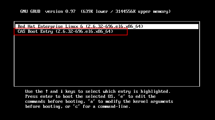
Redhat7.2 (Centos7.2) and later versions
1. View the boot entry that can be edited.
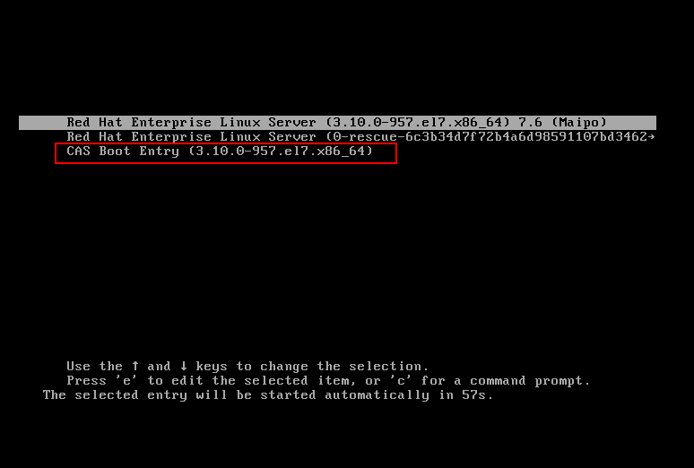
2. Edit the default kernel.
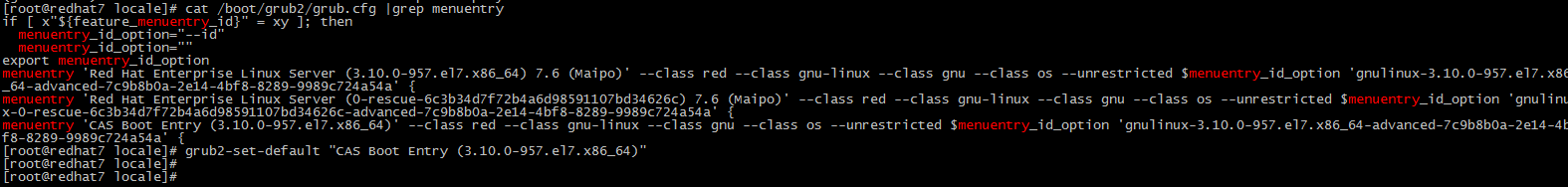
3. Verify that the boot entry has been edited successfully, and restart the server.
![]()
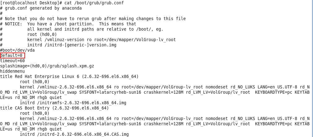
Versions earlier than Redhat7.2 (Centos7.2) and Ubuntu
1. View the boot entry that can be edited.
2. View the grub configuration file. Change the value for the default parameter. In the following figure, the value for the default parameter is changed to 1.
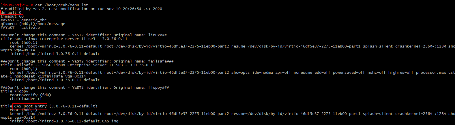
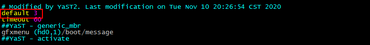
SUSE
1. View the boot entry that can be edited.
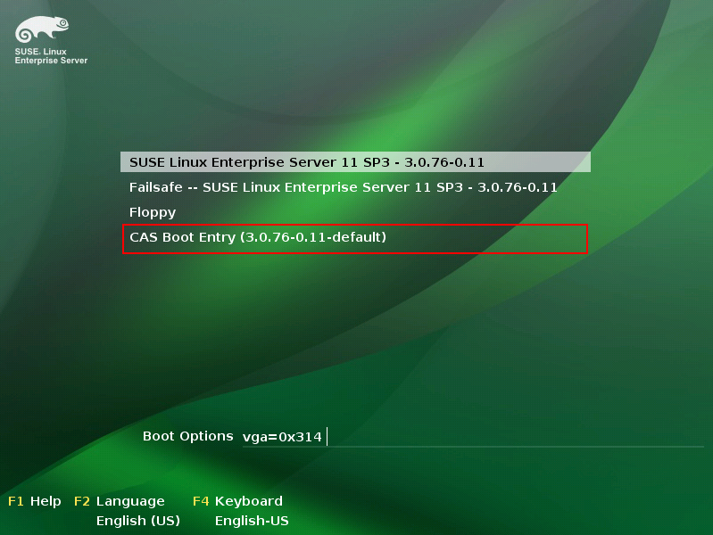
2. Edit the grub boot entry in vi /boot/grub/menu.list. Change the value for the default parameter. In the following figure, the value for the default parameter is changed to 3.
Uninstalling a client
When an installation error or failure occurs, uninstall the client and re-install it.
Uninstalling a Windows client
1. Select Remove DSagent.
2. In the dialog box that opens, click Yes.
3. In the dialog box that opens, click Yes to delete the installation directory.
Uninstalling a Linux client
1. Access the installation directory for the client.

2. Run the uninstall.sh script.
Compatibility
Operating system
See H3C UIS Software and Hardware Compatibility Matrix.
Source disk and file system
See H3C UIS Software and Hardware Compatibility Matrix.
Platform
You can migrate physical hosts or VMs running on virtualization platforms such as VMware and Xen to UIS Manager.
· As a best practice, change the type of disk drivers to IDE or SATA if the kernel version is lower than 2.6.25 for a destination VM that uses the Linux operating system.
· As a best practice use IDE drivers for a destination VM that runs the Windows 2012 operating system. Virtio drivers are supported.
Typical issues
Windows disk offline
This issue occurs because the operating system detects that the hardware environment has changed and takes the disk offline or because the management software takes it offline. This issue does not affect services.
To resolve the issue, reconnect the disk to the system.
Installation package selection
The following figure shows the available client installation packages.
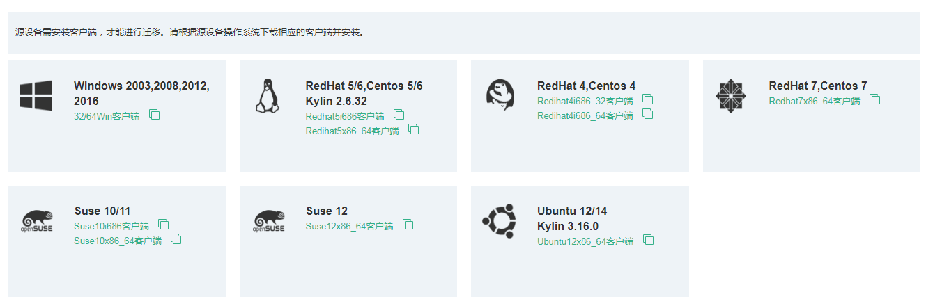
To select a client installation package:
· Windows system: Applicable to all types of Windows systems.
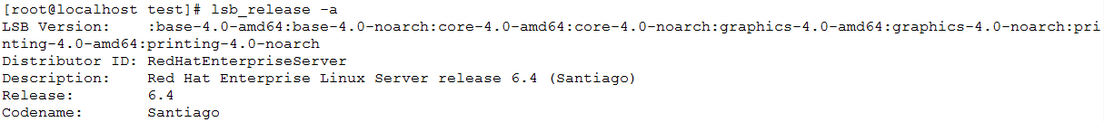
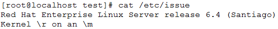
· Linux system: Launch the client to view the system version of RedHat, CentOS, and Kylin 2.6.32.
¡ The system version is RedHat 6.4.
![]()
¡ The system version is Centos 7.4.
![]()
¡ The system version is NeoKylin 3.2.2.
![]()
· Some NeoKylin versions will be displayed as RedHat. If this issue occurs, select a RedHat client. Launch the endpoint, and view the system version of SUSE, Ubuntu, and Ubuntu Kylin.
¡ The system version is SUSE 12 SP2.
![]()
¡ The system version is Ubuntu 14.10.
![]()
¡ The displayed system version is Ubuntu 18.10. The actual system is Ubuntu Kylin.
![]()
· Some Ubuntu Kylin versions will be displayed as Ubuntu. If this issue occurs, select a Ubuntu client.
¡ Launch the endpoint to view the kernel details. If the kernel information is similar to that in the following figure, download an x86_64 client.
![]()
¡ Launch the endpoint to view the kernel details. If the kernel information is similar to that in the following figure, download an x86 client.
![]()
If the client cannot be installed or services cannot start after the client is installed, some configuration in the system might be incompatible with the current client. Please contact Technical Support.
Client installation
Driver selection
1. Select an appropriate CDP driver.
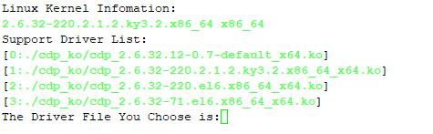
In this example, you select driver 1.
When you select a driver, make sure the suffix for the kernels is the same, for example, default, ky, and xen. If multiple driver packages exist, select the one that has a similar version as the system kernel.
2. Check the driver installation result. Launch the endpoint to identify whether the driver is loaded successfully.
![]()
If the driver is not loaded, please uninstall the client, and re-install the client. When you re-install the client, you must use a root account.
¡ You can try to install all matched drivers. If the following error message is displayed for all drivers, no driver compatible with your operating system kernel is available. Please contact Technical Support.
¡ If the driver is loaded successfully but an error message “insmod: ERROR: could not insert module cdp.ko: Invalid module format” is still displayed in the log, execute the cat /var/log/messages | grep -i cdp command to identify whether the driver is operating correctly.
As shown in the figure, identify whether the CDP version is displayed completely. If the CDP version is displayed incompletely, the driver is operating incorrectly. You must customize a driver to match your operating system kernel. Please contact Technical Support.
3. To customize a driver:
a. Launch the endpoint, and package the file for driver customization.
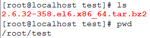
tar -jcvf `uname -r`.tar.bz2 /usr/src/kernels/`uname -r` or tar -jcvf `uname -r`.tar.bz2 /usr/src
If you execute this command, a tar.bz2file will be created in the current directory, the file name of which is determined by the uname –r command.
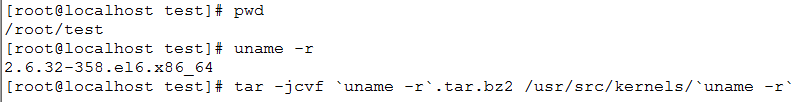
If the system prompts an error message, identify whether the command is correct. As a best practice, do not copy commands in the file directly to your endpoint, because this can cause command execution failure because of format inconsistency. If the command format is correct, identify whether the TAR package is installed on your system. If the TAR software package has been installed and there is still a packaging error, please contact Technical Support.
b. Launch the endpoint, and view the gcc version.
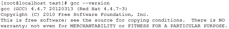
If no version is displayed, the gcc software is not installed. You use Yum to install the gcc software or contact Technical Support and provide the current system image.
c. Launch the endpoint, and view the Kernel version.
![]()
d. Launch the endpoint, and view the system version.
![]()
You can provide either of the three versions.
e. Launch the endpoint, and copy the config file for the current kernel.
![]()
![]()
If an upgrade has been performed for the kernel, you only need to copy the config file.
Package the files and contact Technical Support to request for driver customization.
The system prompts an error message when executing sh xxx.sh to install the client
Symptom
The system prompts an error message when executing sh xxx.sh to install the client.
![]()
Analysis
This issue occurs because the default script execution environment in the Ubuntu operating system is dash shell. The command for running the script cannot be used.
Solution
To resolve the issue:
1. Launch the endpoint, and decompress the client installation package.
2. View information in the client installation package.

3. Install the client.
![]()
4. If the client still cannot be installed or services cannot start after the client is installed, some configuration in your system might be incompatible with the current client. Please contact Technical Support.
The system prompts the "CDAP already installed. Please Uninstall first!" error message when installing the client
Symptom
The system prompts an error message when installing the client.
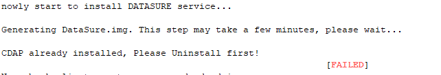
Analysis
The client has been installed but is not uninstalled or data remnants exist after uninstallation. You must first uninstall the client.
Solution
To resolve the issue:
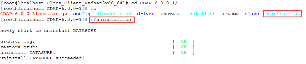
1. Launch the endpoint and access the CDAP-6.0.0-1 directory.
![]()
2. If the directory is not found, install the client again.
3. Uninstall the client.
4. If the issue persists, contact Technical Support.
The system prompts "cat: write error: Broken pipe" when installing the client
Symptom
The system prompts "cat: write error: Broken pipe" when installing the client. This symptom does not affect installation and running of the client.
Solution
If the issue does not affect operation of the cluster, you can ignore this issue.
Some endpoints might be stuck when this message is displayed. If the endpoint where the client is to be installed has been running for a long time and has never restarted, restart the endpoint before installing the client to avoid this issue.
If this issue occurs, you can restart the endpoint and install it again. If an endpoint is still stuck after being restarted, release the memory or stop services and install the client again. If the issue persists, contact Technical Support.
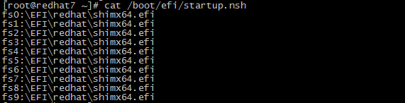
The system requires EFI file selection when the client is installed to an endpoint in UEFI mode
Symptom
The system requires EFI file selection when the client is installed to an endpoint in UEFI mode.
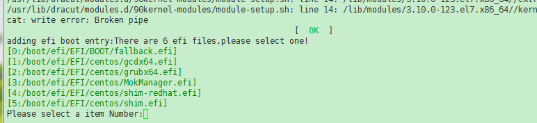
Analysis
This issue occurs because the system will add the EFI file to the datasure boot entry and will list all *.efi files in the system.
Solution
To resolve the issue:
1. Launch the endpoint and view the EFI type.
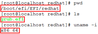
2. Select the grubx64.`efi type.
As shown in the example, selecting a wrong EFI type can only cause DataSure kernel boot entry start failure but does not affect migration. You use the kernel boot entry on the source to start . If the issue persists, contact Technical Support.
Error messages and exceptions in the Web interface
The system prompts "Slave error code is: a0000021"
Symptom
The system prompts "Slave error code is: a0000021".
Analysis
This issue is caused by communication failure between the source and destination.
Solution
To resolve the issue:
1. Launch the endpoint and use Telnet to identify whether it is reachable to ports 4301 and 4302 on the destination if the source endpoint runs the Linux operating system.
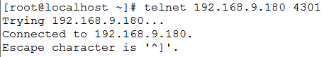
2. If the Telnet operation fails, identify whether a firewall exists between the source and destination. If a firewall exists, add 4301 and 4302 to the exception list. If the destination is a cloud host, you must also identify whether ports 4301 and 4302 are reachable in the security policy on CloudOS. Identify whether an IP for communication with the destination exists. Even if both the source and destination are online, it only indicates that both the source and destination can communicate correctly with the control end.
The system prompts "Slave error code is: a0000034"
Symptom
The system prompts "Slave error code is: a0000034".
Analysis
This issue occurs because of network issues.
Solution
· If this message occurs during the migration process but data transmission is not interrupted, you can ignore this message.
· If the transport network is a public network, data transmission will be terminated when the data transmission speed exceeds the bandwidth limit.
You must change the migration speed based on the bandwidth. Data transmission will be terminated when the data transmission speed exceeds the bandwidth limit.
¡ Bad tracks exist on the disks on the source. Except for the a0000034 error message, the migration process will stop for a period of time, and then change to the suspended state. If you manually start migration, the migration progress will start from zero.
¡ Invalid disks are selected.
The system remains in migrating incremental data state for a long time
Symptom
The system remains in migrating incremental data state for a long time.
Analysis
During the online migration process, new data is already generated when previous data synchronization has not finished yet.
Solution
To resolve the problem:
1. Perform the migration when the system is not busy to reduce data changes.
2. Set the automatic incremental migration interval to a larger value.

Issues on the destination
The destination has the black screen of death issue and the system is unavailable after migration
Symptom
The destination device cannot start and the system is unavailable after migration.
Analysis
· This issue occurs because the fstab file uses a name such as /dev/sda. After the migration, the disk changed to vda.
· The driver for the source device is not compatible with the destination or the first boot disk is not the system disk. Some system and boot mode combinations are not supported. Data on the destination is destroyed during the migration process.
Solution
To resolve the problem:
1. Restart the VM on the cloud platform. If a black screen occurs, boot the ISO image again for the VM to come online, and then perform a data verification.
2. Use a command from the guest OS on the destination or press the corresponding button on UIS Manager to restart the VM. If a black screen still occurs, change the driver type to IDE or VirtIO.
3. If the system disk of the source is not the first boot disk, set the destination disk boot order based on the source disk boot order.
KVM does not support the following operating system and boot mode combinations: Windows system: A black screen will occur if the VM runs the Windows 2008 SP2 64-bit operating system with UEFI boot mode. You must change UEFI boot mode to MBR. Linux system: A black screen will occur if the VM runs the CentOS 6. x system with the UEFI boot mode and the disk driver is VirtIO. You must change the disk driver to IDE.
The destination has a blue screen with a code of 0x0000007B after migration
Symptom
The destination has a blue screen with a code of 0x0000007B after migration.
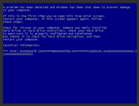
Analysis
This issue is caused by platform compatibility.
Solution
To resolve the issue, change the driver type on the destination to a compatible type, for example, IDE/SATA/VirtIO, and then restart the destination device. Make sure the driver injection operation has been performed before the destination device is restarted.
VM management after migration
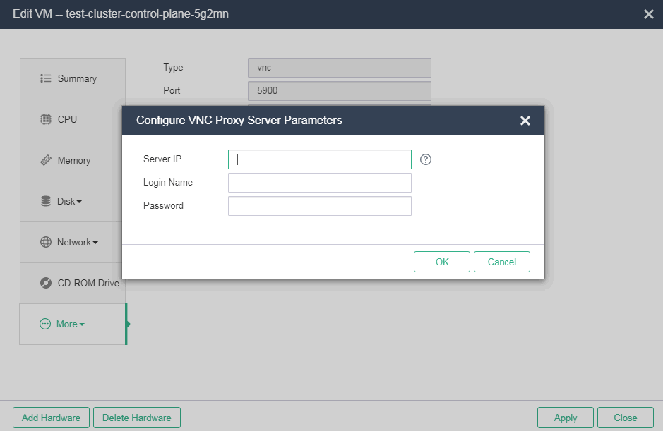
The VNC console for a VM is unavailable on UIS Manager with the HTTPS access mode
Symptom
The VNC console for a VM is unavailable on UIS Manager with the HTTPS access mode.
Analysis
VM VNC proxy is not set on UIS Manager with the HTTPS access mode.
Solution
To resolve the issue, enable VNC proxy, set the UIS Manager IP address or VIP as the proxy server IP, and set the root account and password for SSH login on the page for editing a VM.
CAStools cannot be installed on a VM running the Windows OS after migration
Solution
CAStools cannot be installed on a VM running the Windows OS after migration.
Analysis
The source VM has anti-virus software installed. After migration, UIS Manager determines that the CAStools installation file is a virus file and delete the file.
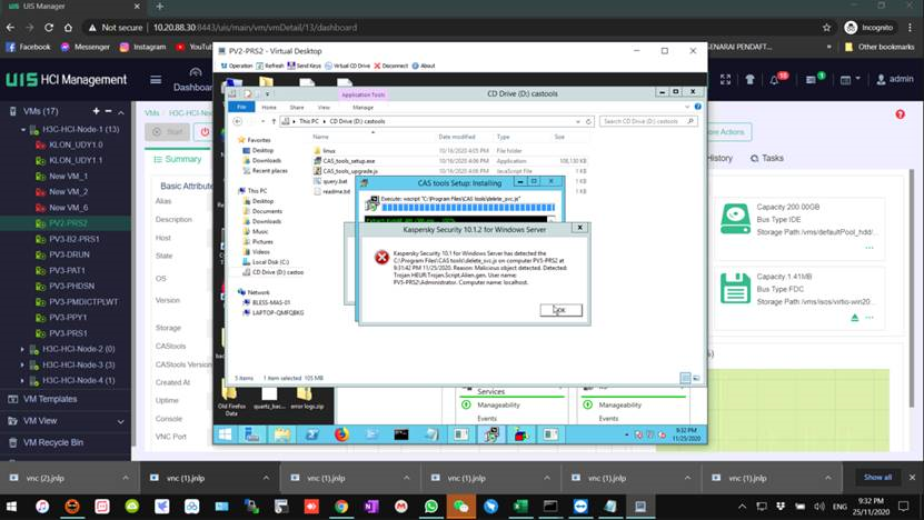
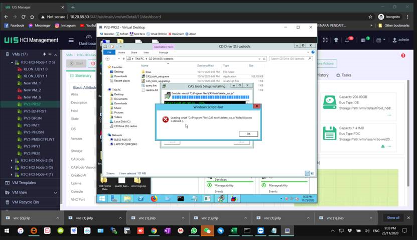
Solution
To resolve this issue, set an anti-virus software allowlist, and add the CAStools installation path to the allowlist. Alternatively, uninstall the anti-virus software. If you are not familiar with the anti-virus software, contact the customer to get help from professionals.
The Linux system enters emergency mode and cannot start after migration
Symptom
After migration, an external file system cannot be mounted correctly because of network issues. The RedHat system enters emergency mode and cannot start. The system prompts a00000034 errors or source device offline error.
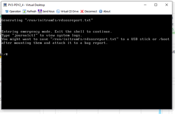
Solution
To resolve the issue:
1. Perform a ping operation to check packet loss between the source and destination to make sure the network is in good condition and perform CDP migration again.
2. After CDP migration, identify whether the system file can be mounted successfully before restarting the VM.
mkdir data
mount /dev/mapper/rhel-root data
ll data
cat /data/etc/fstab
umount data
A VM that uses the SUSE 11 operating system cannot start after migration
Symptom
A VM that uses the SUSE 11 operating system cannot start after migration.
Solution
To resolve the issue, in the PE system, edit the configuration file in the SUSE 11 system and then restart the VM.
1. Before editing the configuration file, make sure your account has the privilege to edit the file. To edit the file, use the sudo vi /etc/fstab and sudo vi /boot/grub/menu.lst commands.
2. Save and exit for the modification to take effect.
3. Edit the /etc/fstab and /boot/grub/menu.lst configuration files in the system directory (not the PE system directory).
4. Change the name of /dev/disk/by-id/ata-TOSHIBA-MK1246GSX-28FGTI70T-part1 to /dev/sda1.
Partition name:
¡ /dev/disk/by-id/ata-TOSHIBA-MK1246GSX-28FGTI70T-part1 > /dev/sda1
¡ /dev/disk/by-id/ata-TOSHIBA-MK1246GSX-28FGTI70T-part2 > /dev/sda2
Exporting VMs as OVA or OVF templates
About this task
Open Virtualization Format (OVF) is an open standard defining the file format that allows for compatibility of VMs across management platforms. UIS Manager supports OVF templates exported from CAS CVM, VMware vSphere, Oracle VM, and ZTE iECS systems.
Restrictions and guidelines
· The VMs must be shut down.
· The system supports only VM template files in tar.gz, zip, or ova format. If a VM template exported from a third-party system is a folder, compress the folder as a tar.gz, zip, or ova file first.
· The time required for uploading an OVF template depends on the disk size that is occupied by the VM image file. As a best practice, adjust the idle timeout to ensure that the OVF template can be uploaded without interruption.
· After you deploy an OVF template exported from a third-party system, install CAStools for the VM online and then change the disk bus type to high-speed offline to improve the disk I/O performance.
· The current software version does not support deployment of OVF templates that contain disk partitions.
Procedure
The following uses VMware vSphere as an example.
1. On the VMWare ESXi platform, remove the VMwaretools for a VM, shut down that VM, select File > Export to OVF, and export the VM as an OVA, a single-file archive.
2. Log in to UIS Manager.
3. On the top navigation bar, click VMs or Hosts.
4. Perform one of the following tasks:
¡ Select a VM, click More on the host tile, and then select Deploy OVF Template.
¡ Select a host from the navigation pane to enter the host overview page, click More Actions, and then select Deploy OVF Template.
Figure 47 Deploying an OVF template
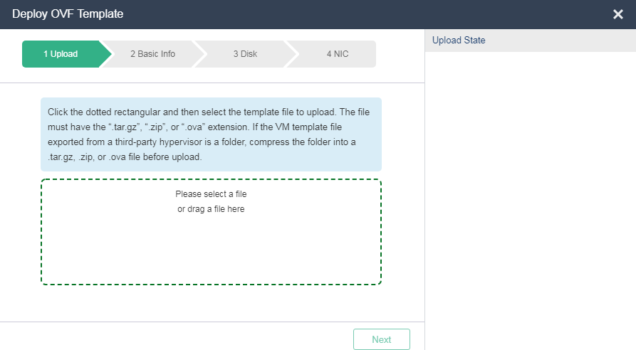
5. Follow the wizard to deploy VMs by using the OVF template.
Migrating a VM through the cloud rainbow feature in UIS Manager
Cloud rainbow provides UIS resource sharing and manual VM migration between data centers without service interruption.
Restrictions and guidelines
· Do not connect hosts to any UIS Manager during VM migration.
· VMs cannot be migrated through the cloud rainbow feature between hosts with the same but on different UIS Managers. For example, UIS Manager A has hosts CVK 1 through CVK 3, and UIS Manager B has hosts CVK 1 through CVK 4. VMs can be migrated from UIS Manager A to host CVK 4 on UIS Manager B, but cannot be migrated from UIS Manager B to UIS Manager A.
· For successful VM migration, make sure the distance between the data centers where the two UIS Managers are located is no longer than 30 km (18.64 miles).
· As a best practice, use 10-GE link aggregation or directly connect the two UIS Managers with fibers. Make sure the UIS Managers are reachable to each other at Layer 3.
· As a best practice, migrate VMs when memory change is not so frequent, because online VM migration requires frequent VM memory synchronization.
· For cloud rainbow to take effect, make sure the source and destination resource pools have port profiles and vSwitches with the same names.
· VMs that have optical drives, floppy disks, PCIs, USB devices, or block devices attached cannot be migrated.
· Service interruption might occur during the last phase of online VM migration. For example, if you continuously ping the IP address of the VM being migrated, the number of dropped packets will be 0 to 2, depending on the memory usage and memory change of the VM.
· The VM console will be disconnected after a VM is migrated to the destination UIS Manager, because the IP address and VNC port of the CVK host attached to the VM changed after migration.
· The IP address of a VM does not change after migration no matter whether this IP address is a static or DHCP-assigned IP address.
· For successful migration of a VM whose data cache mode is None or Directsync and whose disk is in an NFS, shut down the VM before migration.
Hardware and software requirements
Hardware requirements
This document is not restricted to a specific server model. The configuration in this document might differ from the configuration in actual deployment.
The hardware used in this document is shown in Table 1. The hardware requirements are not intended to be mandatory or recommended during actual deployment. You can complete configuration as long as your server is compatible with H3C UIS Manager.
Table 7 Local site hardware requirements
|
Hardware |
Requirements |
|
Server model |
H3C R4900 G3 |
|
Server quantity |
3 |
|
CPU |
2 × 12-core Intel(R) Xeon(R) Silver 4116 CPU @ 2.10GHz CPUs |
|
Memory |
128 GB |
Table 8 Remote site hardware requirements
|
Hardware |
Requirements |
|
Server model |
H3C R4900 G3 |
|
Server quantity |
4 |
|
CPU |
2 × 12-core Intel(R) Xeon(R) Silver 4116 CPU @ 2.10GHz CPUs |
|
Memory |
128 GB |
Software requirements
|
Software |
Version |
|
H3C UIS |
E0709 |
Network diagram
Figure 48 H3C UIS cloud rainbow network diagram
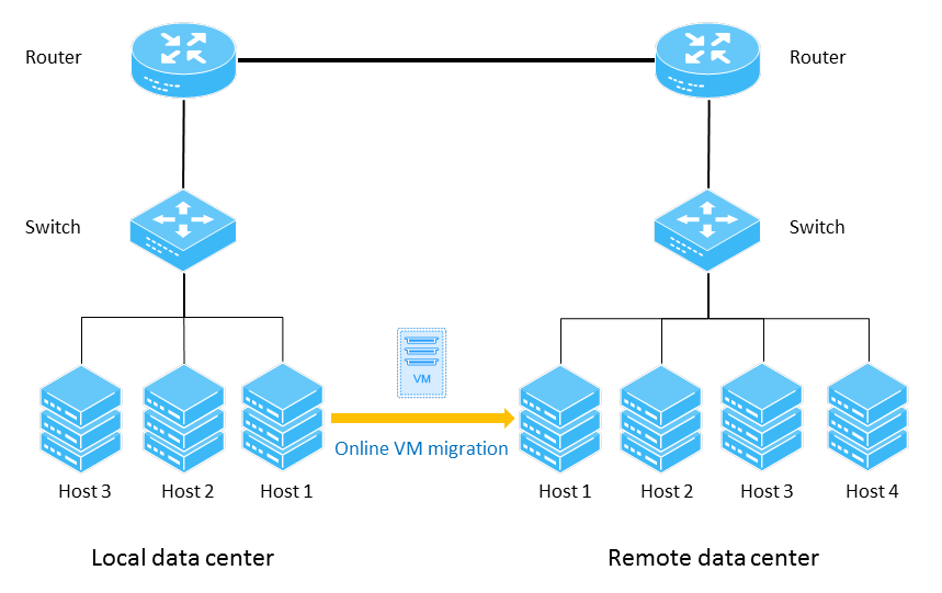
Procedure
Creating a VM
1. Log in to the UIS manager of the local data center.
2. Click VMs on the top navigation bar, and then click Add.
Figure 49 VMs in the local data center
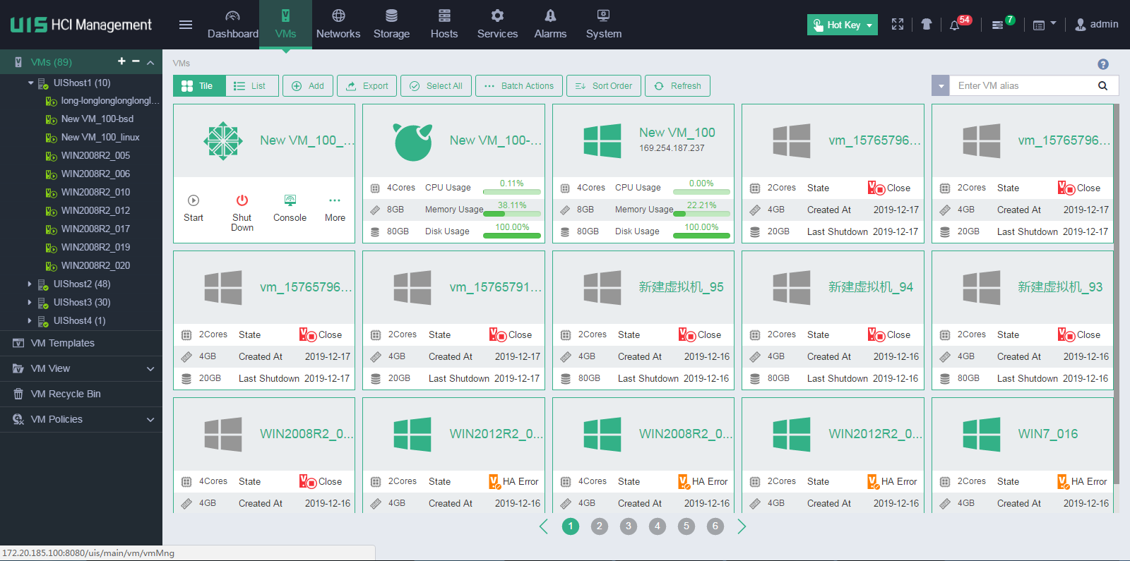
3. Configure the VM settings as described in Table 3, and then click Finish.
Figure 50 Configuring VM parameters
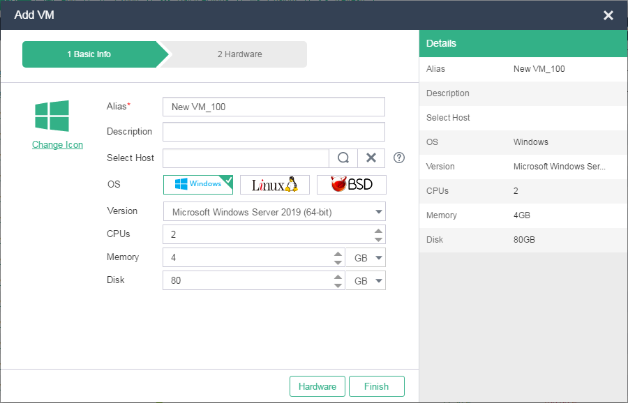
|
Item |
Requirements |
|
CPUs |
1 socket 4 cores |
|
Memory size |
4 GB |
|
Disk size |
20 GB (local disk) |
|
Bus type |
Use the default setting (1 × Virtio, high-speed) |
|
Storage format |
Use the default setting (QCOW2) |
|
Disk caching mode |
Use the default setting (directsync) |
|
vNIC type |
Use the default setting (1 × Virtio) |
|
vSwitch |
Use the default setting (vSwitch0) |
|
Port profile |
Use the default setting |
|
IP address/subnet mask |
172.20.172.213/24 |
|
|
IMPORTANT: The settings in Table 3 are configured for a test environment. In a production environment, you must configure VM settings such as CPU, memory, disk, NIC, OS, and custom settings such as disk partition, account, and component installation based on the actual requirements of your system. |
4. Start the VM and install an operating system for the VM.
Figure 51 Installing an operating system for the VM
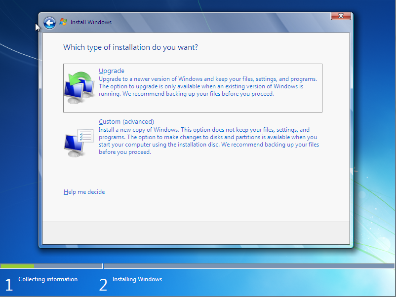
5. Install CAStools for the VM.
Figure 52 Installing CAStools
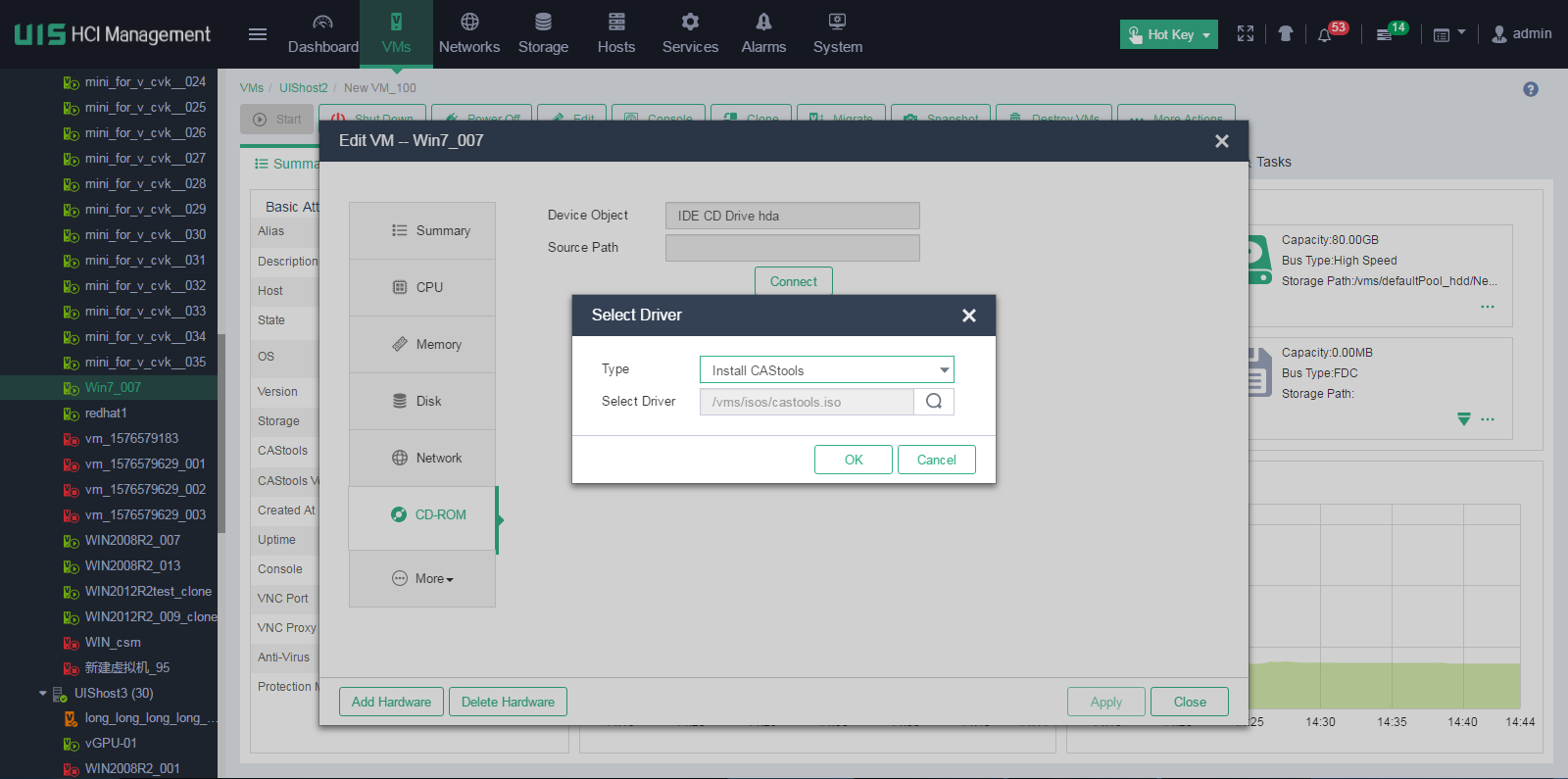
Figure 53 Installing CAStools for the VM
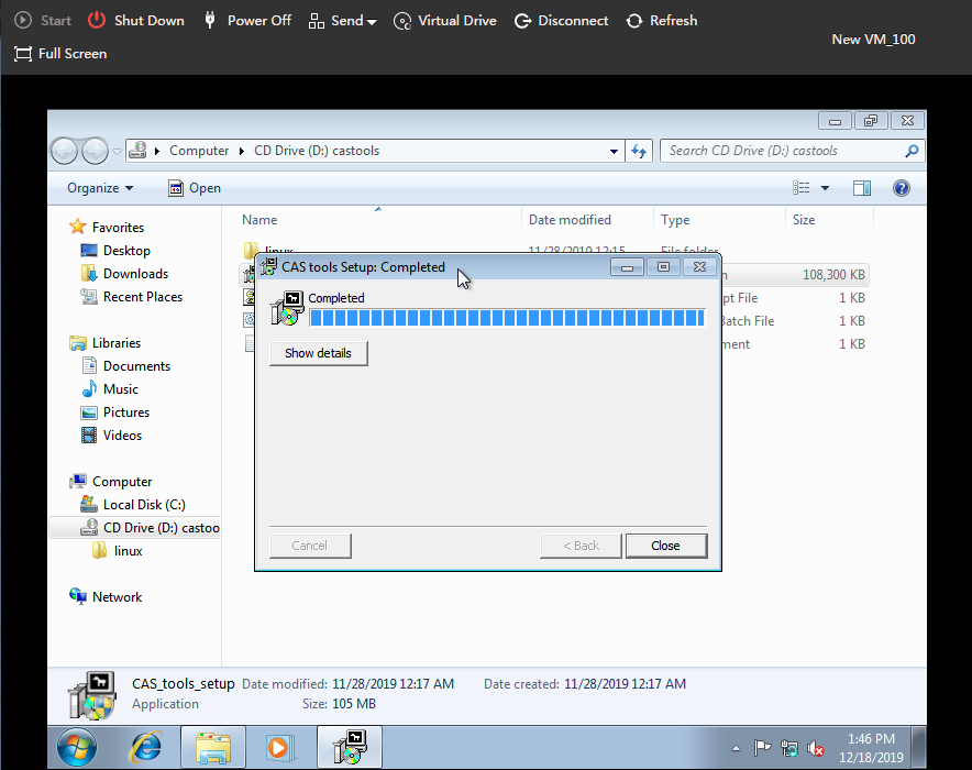
6. Configure IP address settings for the VM manually or through CAStools.
Figure 54 Configuring IP address settings for the VM
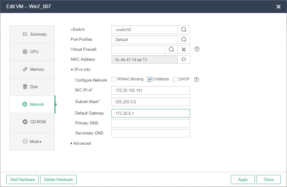
7. During VM migration, download files from an FTP server to verify that VM service is not affected when the VM is being migrated.
Make sure an FTP client has been installed on the operating system of the VM.
Figure 55 Verifying VM service state during migration
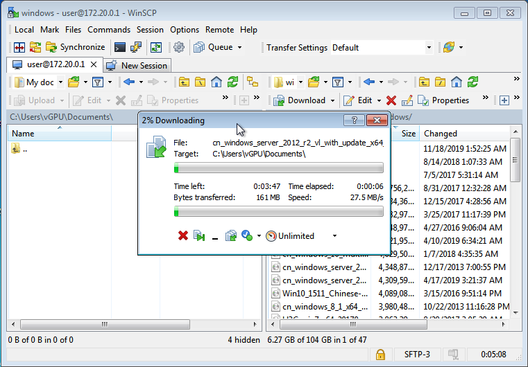
Performing online VM migration
1. On the top navigation bar, click Services, and then select Cloud Rainbow from the navigation pane.
2. Click the Add icon ![]() .
.
If you add a UIS Manager for the first time, a dialog box opens and prompts you to configure the local data center. Click OK in the dialog box, and then configure the local data center parameters.
Figure 56 Local data center
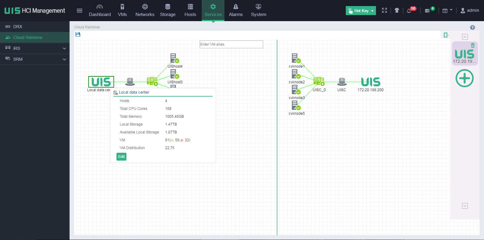
3. Specify a name for the local data center, and the enter the management IP address of the UIS Manager, and then click OK.
Figure 57 Configuring the local data center

4. On the top navigation bar, click Services, and then select Cloud Rainbow from the navigation pane.
5. Click the Add
icon ![]() to the right of the page.
to the right of the page.
6. Configure the parameters as described in Table 4, and then click OK:
Figure 58 Adding a remote data center
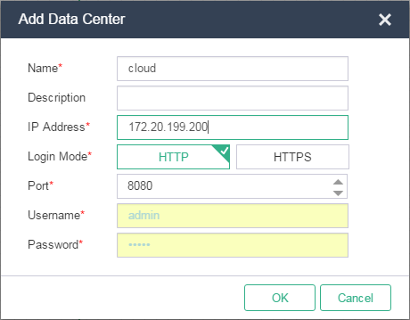
Table 10 Data center parameters
|
Parameter |
Description |
|
Name |
Specify a name for the data center. A maximum of 36 Chinese or English characters. Required. |
|
Description |
Specify a description for the data center. A maximum of 120 Chinese or English characters. Optional. |
|
IP Address |
Enter the IP address of the data center. It must be an IPv4 address in dotted decimal notation. Required. |
|
Login Mode |
Select a method for logging in to the data center. Required. |
|
Port |
Enter the port number for accessing the data center. If HTTP is used, the default port number is 8080. If HTTPS is used, the default port number is 8443. Required. |
|
Username |
Enter the username for accessing the data center. Required. |
|
Password |
Enter the password for accessing the data center. A maximum of 32 Chinese or English characters. Required. |
The system displays both the local data center and remote data center.
Figure 59 Local and remote data centers topology
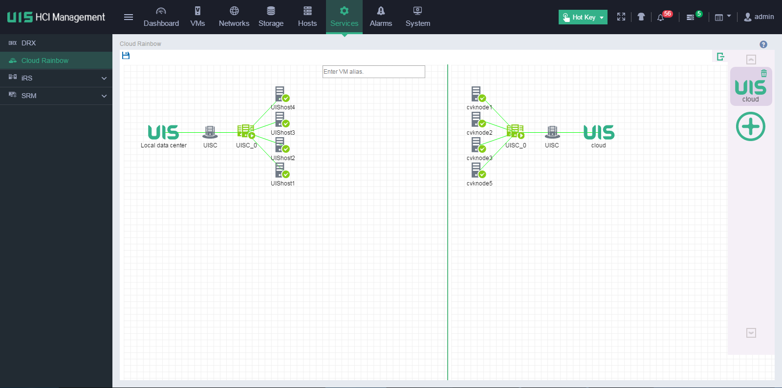
7. Enter a VM alias in the search box, and then press Enter or double click a host to view all VMs on the host, and then drag the target VM to the destination host on the remote UIS Manager.
Figure 60 Viewing VM information
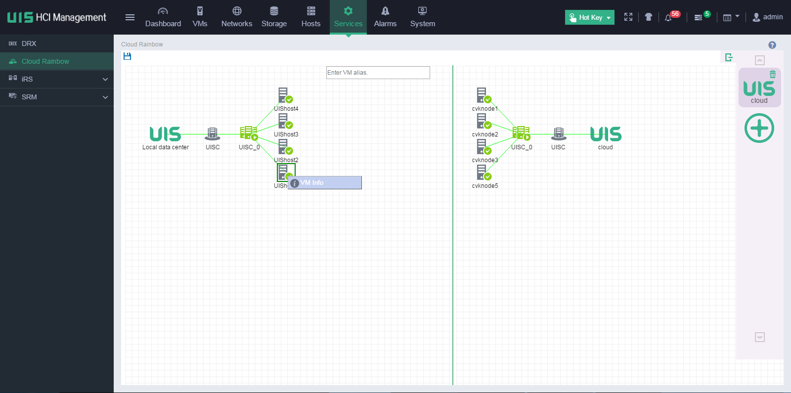
Figure 61 Manually migrating the VM to the remote data center
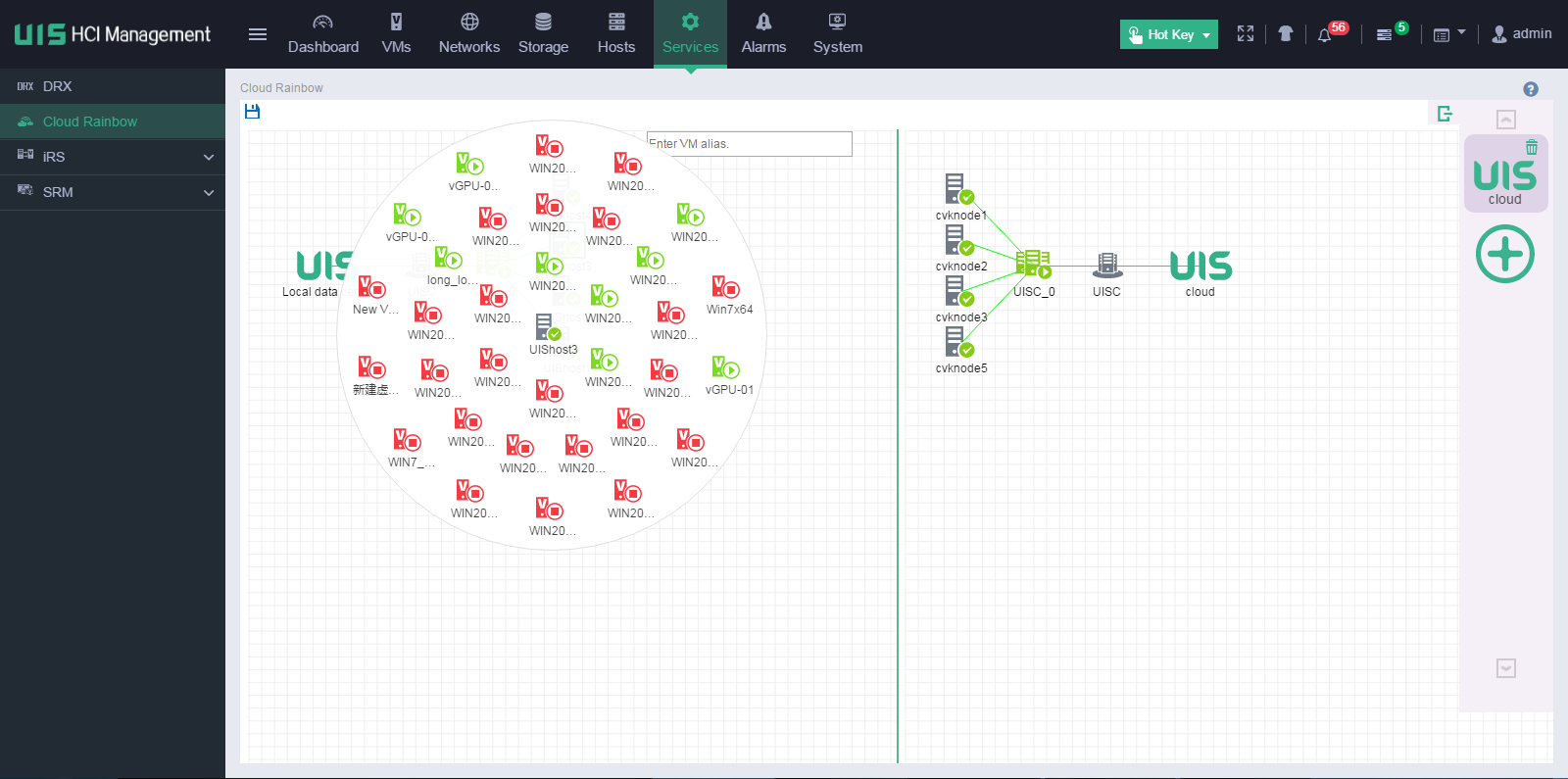
8. In the configuration box that opens, configure the parameters as needed, and then click Next.
¡ Timeout: Enter the migration timeout for migrating running VMs. The system suspends a VM if the VM cannot be migrated before the timeout timer expires and restores the VM after migration.
¡ Compress: Select this option to compress the data to be transmitted.
9. Select the destination storage pool, and then click Finish.
Figure 62 Selecting the destination storage pool
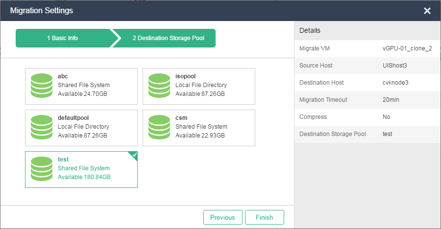
10. Open the task console to view VM migration progress.
Figure 63 Viewing VM migration progress from the task console
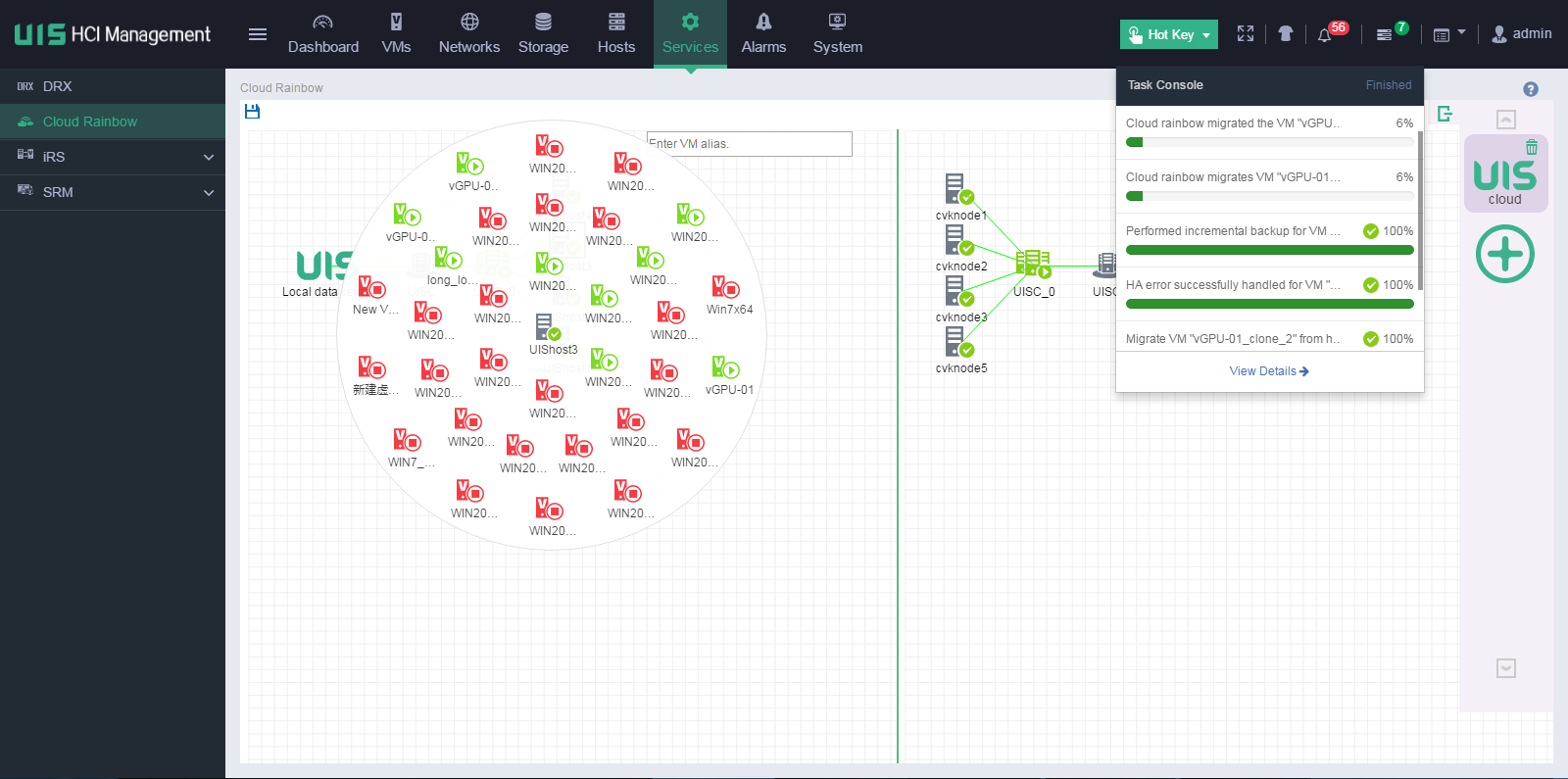
11. On a VM or PC that is reachable to the VM being migrated at Layer 3, ping the IP address of the VM to view the VM state during migration.
Figure 64 Viewing VM migration state

12. Verify the migration result:
a. On the task console, view the migration progress, which is 100%. Then log in to the UIS Manager in the remote data center to view the VM state. The system displays that the VM is in running state, and its IP address does not change.
Figure 65 Viewing information about the VM after migration through cloud rainbow
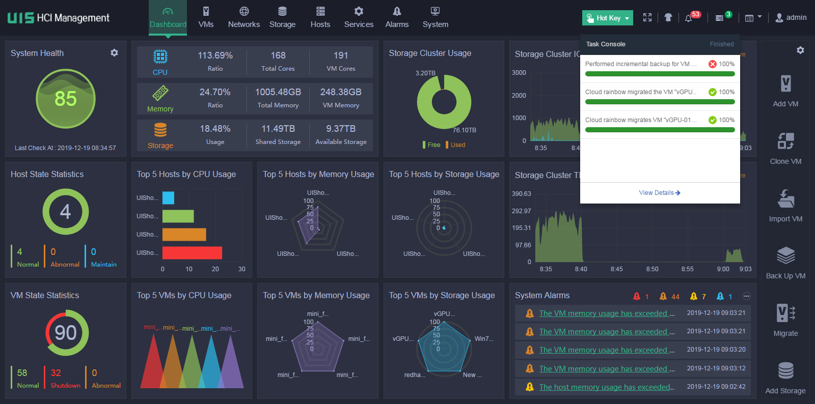
b. View cloud rainbow VM migration operation log in the UIS Manager operation log list.
Figure 66 Viewing VM migration operation log
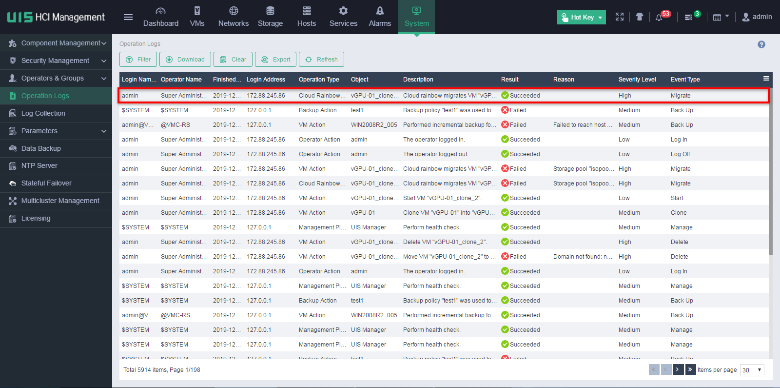
c. Log in to the remote UIS Manager, and access the migrated VM from the console. The system displays that FTP download is being performed on the VM's operating system.
Figure 67 Viewing the state of the migrated VM through FTP

Troubleshooting
The VM migration process is stuck in 99%
Symptom
The online VM migration process is stuck in 99% on the task console for a long time and the system does not prompt a migration failure.
The CPU usage and memory usage have increased to 99% or 100%, the CAStools is in stopped state, and even VM services are affected.
Reason
· The memory size of the VM is at least 16G or 32G.
· The memory usage change is great because of the service running requirements of the VM.
· If the storage is also migrated when a VM is migrated, the VM disk space is large, 1T or higher, disk I/O read and write is frequent, and great data change.
· The network is in poor condition, for example, the management network bandwidth is too low or the I/O latency is high.
Solution
To resolve the issue:
1. Log in to the destination host to check for the scp process (with the ps –elf command) and the disk size of the VM. If the scp process does not exist and the disk size is the same as that of the source VM, the migration task is about to finish. As a best practice, wait for the migration task to finish.
2. If the migration task cannot finish for a long time, log in to the source host to suspend or shut down the VM and wait for the migration of dirty data.
3. If you confirm that the VM cannot be migrated or the migration task must be stopped manually, you must kill the scp process on the destination host, and then restart the tomcat8 process from the CLI of the source host.
To kill the scp process, use the kill –pid command, where pid is the ID of the SCP process. You can view the ID by using the ps –elf command. To restart the tomcat8 process, execute the service tomcat8 restart command. Before restarting the tomcat8 process, make sure no other processes are running except for the migration process. The migration task will be closed after the tomcat service is restarted. If the VM state is not restored, shut down and then restart the VM.
|
|
CAUTION: Restarting the tomcat service will terminate all running tasks displayed on the Web interface. |
4. To migrate the VM through the cloud rainbow feature, shut down the VM and perform an offline migration.
Migrating a VMware VM from the CLI
About this task
This migration mode does not require any agent or client software at both the source and destination. You can migrate a VMware VM image file to UIS Manager by executing commands at the CLI. Service interruption will occur during the migration process.
Procedure
1. Upload the VMware VM file to a host managed in UIS Manager.
In this example, the VM file name is 1.ova.
Figure 68 Changing the name of the VM file
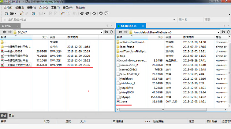
2. If the VM images file is an OVA package file, you must decompress the package file before you can convert the VM. As a best practice, create a temporary directory and decompress the OVA file in that directory.
For example, create directory tmp in the /vms/defaultShareFileSystem directory, move the VM package file 1.ova to the temp directory, and then execute the tar command to decompress the file.
root@cvknode1:/vms/defaultShareFileSystem0# mkdir tmp
root@cvknode1:/vms/defaultShareFileSystem0# ls
root@cvknode1:/vms/defaultShareFileSystem0# mv 1.ova
tmp
root@cvknode1:/vms/defaultShareFileSystem0# cd tmp
root@cvknode1:/vms/defaultShareFileSystem0/tmp# tar –xf 1.ova
3. Execute the following command to convert the VM image format to qcow2.
qemu-img convert -O qcow2 filename oute_filename
The filename argument represents the file name of the source VM image, and the out_filename argument represents the file name of the converted VM image. In this example, the qemu-img convert -O qcow2 ______-disk.vmdk ykt-1 command is executed.
Figure 69 Viewing the name of the file with a suffix of .vmdk
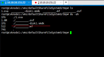
4. Move the qcow2 image to a storage pool for VM creation.
In this example, an image named ykt-1 is moved to the /vms/defaultShareFileSystem0 storage pool.
root@cvknode1:/vms/defaultShareFileSystem0/tmp# mv ykt-1/vms/defaultShareFileSystem0
root@cvknode1:/vms/defaultShareFileSystem0/tmp# cd ..
root@cvknode1:/vms/defaultShareFileSystem0#ls
5. Create a VM in UIS Manager. Select the converted image file and set the disk bus type to IDE. For the VM to start up correctly, you must select IDE as the bus type.
In this example, image ykt-1 is selected from the defaultShareFileSystem0 storage pool.
Figure 70 Selecting image file
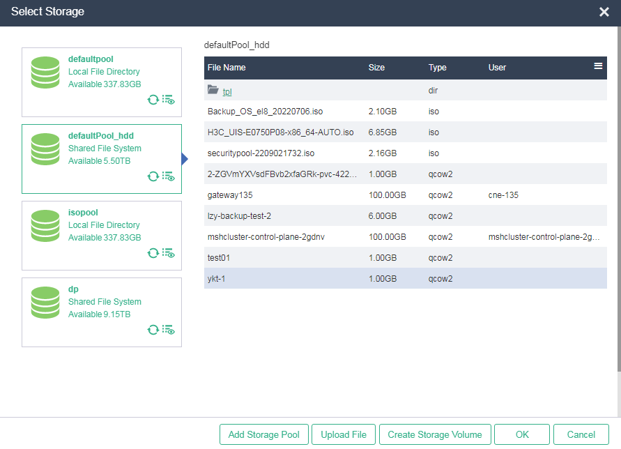
Figure 71 Selecting the bus type
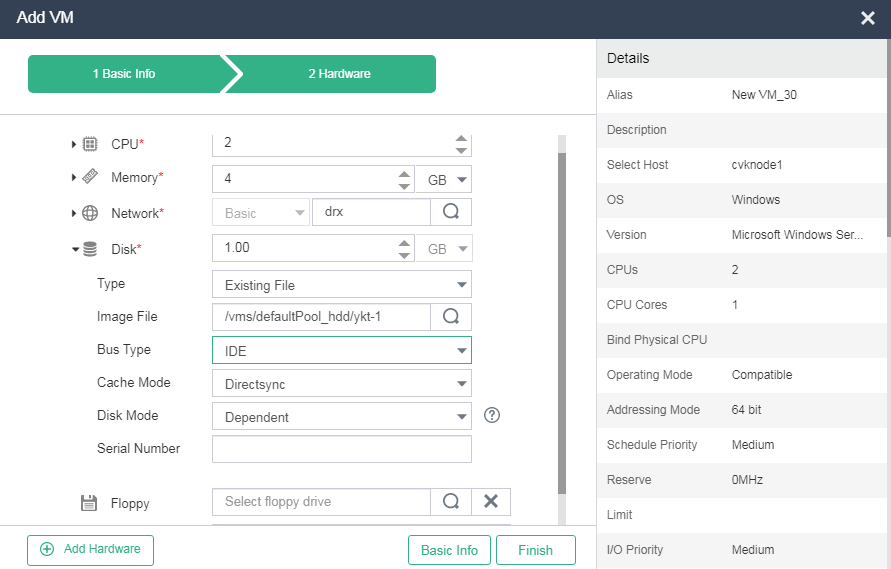
6. Start the VM and verify that the VM can operate correctly.
7. Delete the temporary directory/vms/defaultShareFileSystem0/tmp.
Appendix Gathering physical host and VM migration information
Gathering operating system information for a physical host
A physical host typically runs a Windows or Linux operating system.
· Method 1: Access Computer > Attributes to view operating system information.
· Method 2: Execute the systeminfo command from the CLI.
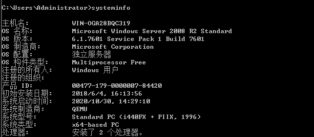
· Method 1: Execute the uname -a or cat /proc/version command to view kernel version information for the Linux operating system.
![]()
![]()
· Method 2: Execute the cat /etc/issue command to view the issued Linux operating system version. For a CentOS or RedHat operating system, the cat /etc/issue command cannot obtain the issued version. To do so, execute the cat /etc/redhat-release command.
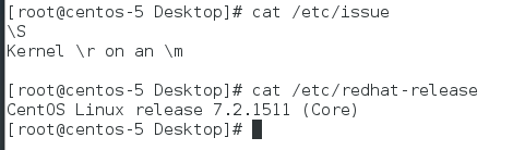
Gathering hardware configuration and workload information for a physical host that runs a Windows operating system
Gathering hardware configuration
Hardware configuration for a physical host includes CPU, memory, disk type, disk capacity, and disk I/O information.
Access Computer > Properties to view the CPU model, system type, and memory size.
Access Computer > Storage > Disk Management to view the disk capacity and usage.
Gathering load information
Performance Monitor (Perfmon) is a performance monitoring tool that comes with Windows. It provides graphical system performance real-time monitor, performance log, and alert management. By adding performance counters, you can monitor hundreds of indicators for multiple objects such as CPU, memory, network, disk, and process.
To use the tool, perform the following steps:
1. Click Start, enter perfmon in the search field, and then press Enter.
2. From the left navigation pane, select Performance Monitor > Data Collector Sets. In the right pane, right-click User Defined, click New, and then click Data Collector Set. If no performance monitor template is available, you can create one.
3. Click Next. Under Create data logs, select Performance counter, and then click Next.
4. Set the sample interval, and then click Add.
5. Add performance counters one by one in the order shown in the following figure. Select Show description. Select counters from the Available counters area, and then add them to the Added counters area. Click OK.
6. Click Next.
7. Specify a location where you want to save the data, and then click Finish. In the right panel, right-click a performance counter, and then select Properties. Right-click Properties, configure the required parameters, and then click OK.
8. Configure a schedule. As a best practice, specify a time range of seven days.
9. Click Start. Check the report for the maximum, minimum, and average values, and the line graph for each indicator.
Gathering hardware configuration and workload information for a physical host that runs a Linux operating system
Gathering hardware configuration
To gather CPU information, use the cat/proc/cpuinfo | grep name | cut-f2-d: | uniq-c command.
![]()
To gather memory information, use the free –h command.
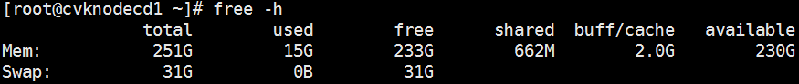
To gather disk capacity information, execute the smartctl command. The User capacity field in the output from this command displays the total disk capacity.
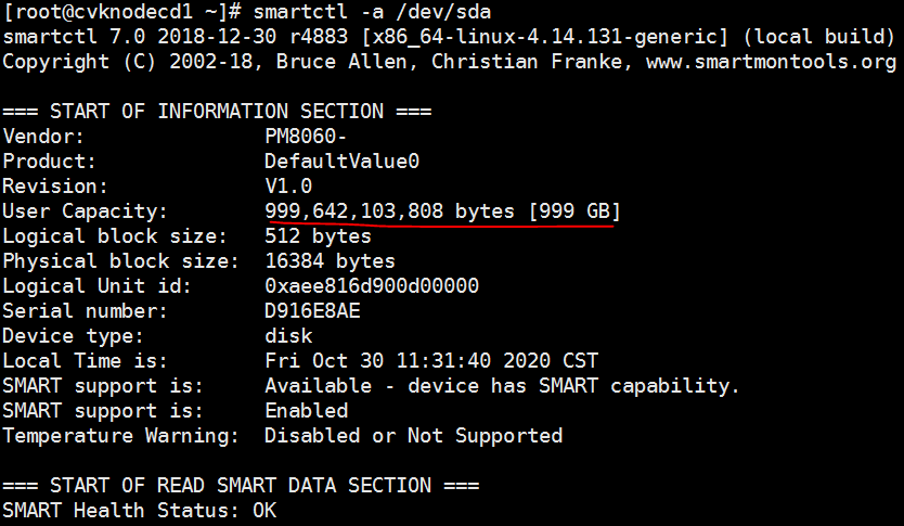
To gather disk usage information, execute the df -hT command.
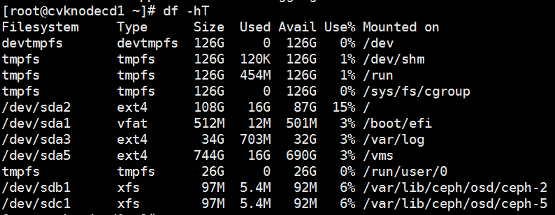
Gathering load information
nmon is a monitor and analysis tool widely used on Linux operating systems. It can capture system resource usage information in real time during system operation.
Download the software package from the nmon official website at http://nmon.sourceforge.net/pmwiki.php?n=Site.Download</8624>. If you cannot download the nmon tool, see 3.3.3 to resolve the issue.
For example, download nmon_linux_x86_64, and then run nmon. Then add the chmod u+x nmon_linux_x86_64 command.
Execute the ./nmon_linux_x86_64 command.
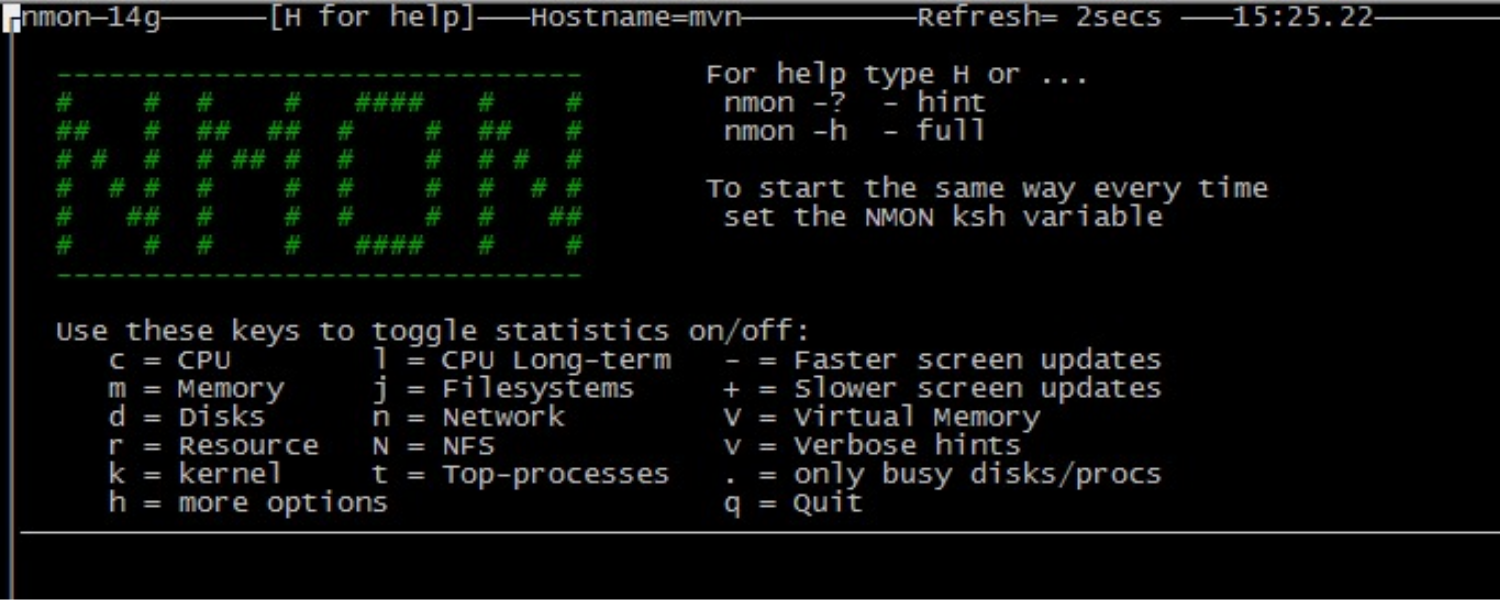
To display the CPU usage, press c. To display the memory usage, press m.
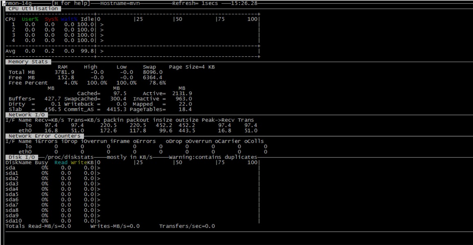
Rename nmon_linux_x86_64 as nmon and add it to /usr/bin/;/usr/local/bin, and then you can use the nmon command to run nmon.
Obtaining the performance data file by using the nmon command
Use the nmon-s5-c100-f -m/home/hobbs command to monitor system data and write the data into a file.
· -s5—The system collects data every 5 seconds.
· -c100—The system performs 100 collections.
· -f—The name of the generated data file contains the time when the file was created.
· -m—Directory where the generated data file is saved.
To create a scheduled data collection task, add the following command in crontab:
0 0 * * * nmon -s300 -c288 -f -m /home/hobbs > /dev/null 2>&1
You can define the data collection interval.
Generating a graph file
To generate a graph file, download the nmon tool from the following website: http://nmon.sourceforge.net/pmwiki.php?n=Site.Nmon-Analyser
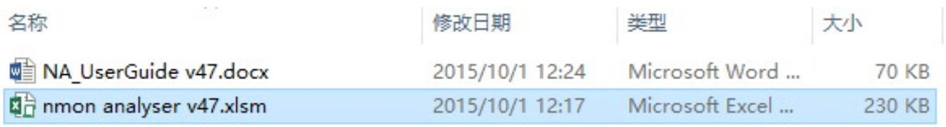
The Word file is a usage guideline. The Excel file is the tool for generating a graph file.
To generate a graph file:
1. Copy the data file generated in the Linux system to Windows.
2. Double-click nmon analyzer v47.xlsm.
3. Click Analyze nmon data, select the data file copied from Linux, and then click Open.
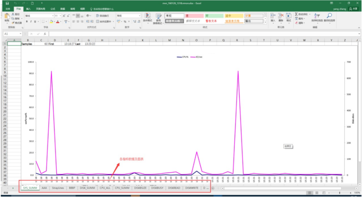
Gathering information by using Linux commands
For sites that have high requirements on information security, use Linux commands to manually gather information.
Gathering information by using the top command

· The first line:
¡ 12:47:09—Current time of the system.
¡ 1 days,23:24—The system has been running for 1day, 23 hours, and 24 minutes without restart.
¡ 1 users—One user has logged in to the system.
¡ load average—6.67, 6.80, 7.04, where the numbers represent the load at the first minute, 5 minute, and 15 minute, respectively. The system checks the number of active processes every 5 seconds and calculates the load average data by using a specific algorithm. If any number divided by the number of logical CPUs exceeds 5, the system is overloaded.
· The second line:
¡ Tasks—Number of tasks (processes) in the system. Running: 3, sleep: 470, stopped: 0, zombie: 4
· The third line displays the CPU usage:
¡ 14.0% us—CPU used by the user space, in percentage.
¡ 7.6% us—CPU used by the kernel space, in percentage.
¡ 0.0% ni—CPU used by processes that have their priority changed in percentage.
¡ 78.4% id—Idle CPU in percentage.
¡ 0.0% wa—Percentage of time that CPUs were idle during which the system had pending disk I/O requests.
¡ 0.0% hi—CPU used by hardware IRQ in percentage.
¡ 0.0% si—CPU used by software interrupts, in percentage.
· The fourth line displays the memory usage:
¡ 26359508k total—Total physical memory capacity.
¡ 24451923k used—Used memory capacity.
¡ 16792696K total—Total idle memory capacity.
¡ 2283160k buffers—Cached memory.
· The fifth line displays the usage of the swap partition:
¡ 33554428k total—Total capacity of the swap partition.
¡ 0k used—Used capacity.
¡ 33554428k total—Total idle capacity.
Gathering information by using the free command
To gather Linux memory usage, execute the free -m command. The available memory is free + buffers + cached.
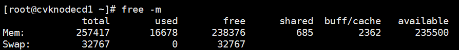
Gathering information by using the iostat command
To display the IO state of the current disk, execute the iostat command, including IOPS, throughput, response time, and disk business. A commonly used command is iostat -x -m 5, where -x displays data related to IO, -m displays the throughput of the disk in MB, and 5 represents the collection interval.
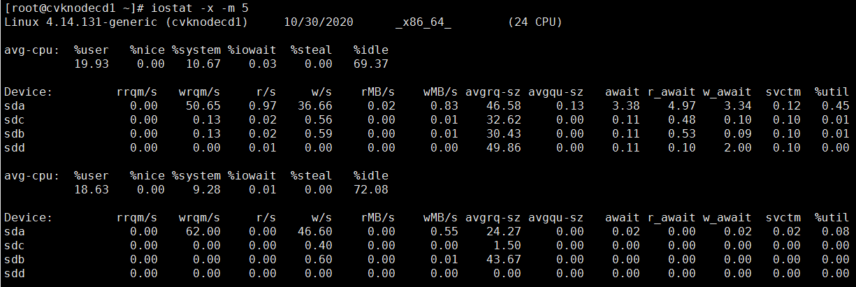
Gathering information by using the df command
The df command displays the amount of disk space available on the file system. The df -h command displays the file system disk space statistics in “human-readable” format.
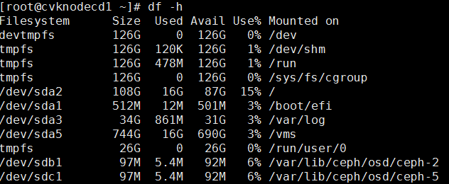
Gathering VM migration information
To gather VM migration information, access the source virtualization platform to gather operating system, flavors, and load information. Alternatively, you can execute related commands from the operating system.
Gathering business system type information
You must contact the customer to obtain the business system type, for example, Oracle, Oracle RAC, and mail and voice office system.