- Released At: 13-09-2023
- Page Views:
- Downloads:
- Table of Contents
- Related Documents
-
EPS-EIA Collaboration-Based Access Control
Configuration Examples
Software version: EIA (E6204) and EPS (E6203)
Document version: 5W100-20230906
Copyright © 2023 New H3C Technologies Co., Ltd. All rights reserved.
No part of this manual may be reproduced or transmitted in any form or by any means without prior written consent of New H3C Technologies Co., Ltd.
Except for the trademarks of New H3C Technologies Co., Ltd., any trademarks that may be mentioned in this document are the property of their respective owners.
The information in this document is subject to change without notice.
Contents
Example: Configuring EPS-EIA collaboration-based access control
Configuring EPS and EIA collaboration
Manually setting an endpoint to incompliant
Configuring endpoint impersonation for access
Using a compliant endpoint to come online again
Introduction
The following information provides an example of configuring EPS and EIA collaboration to control access for detected endpoints. When an unauthorized access endpoint is detected, EPS collaborates with EIA to add the endpoint to the blacklist and forces the incompliant endpoint device to go offline. After you replace the incompliant endpoint device with a compliant one and approve the endpoint to be compliant, the compliant device can come online.
Feature usage guidelines
Application scenarios
The following information applies to enterprise networks requiring access control for detected endpoints through EPS and EIA collaboration.
Prerequisites
Make sure the EIA and EPS components have been deployed.
A minimum of two different types of endpoint devices that support MAC address spoofing are prepared.
A scanner is installed and managed by EPS.
Example: Configuring EPS-EIA collaboration-based access control
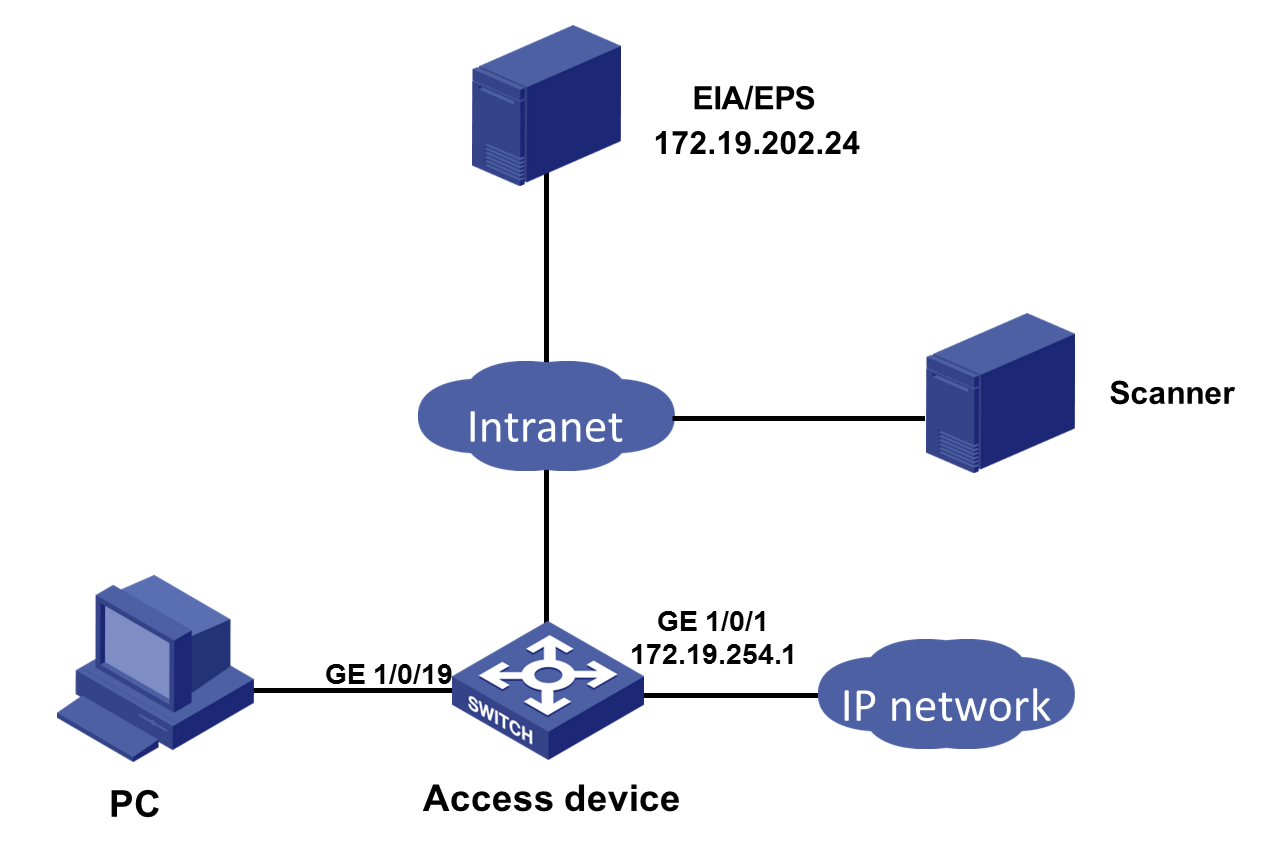
Network configuration
A company plans to use EPS and EIA collaboration to control access for detected endpoints. Configure the network as shown in Figure 1. Set the IP addresses of both the EIA server and EPS server to 172.19.202.24.
Restrictions and guidelines
In a cluster deployment, specify the northbound service virtual IP as the IP address of the EIA or EPS server. Do not specify the node IP address of the EIA or EPS server.
To identify the northbound service virtual IP of the EIA or EPS server in a cluster deployment:
1. Enter https://ip_address:8443/matrix/ui in the address bar of the browser to open the Matrix page. ip_address represents the northbound service virtual IP or node IP address.
2. On the top navigation bar, click DEPLOY.
3. From the navigation pane, select Clusters. Click the Cluster Parameters tab.
4. Use the IP address in the Northbound Service Virtual IP field as the IP address of the server.
|
|
NOTE: The northbound service virtual IP (10.114.119.150) in the screenshot is for illustration only. It differs from the one used in this example. |
Figure 2 Viewing IP address of the EIA or EPS server

Software versions used
This configuration example was created and verified on EIA (E6204), EPS (E6203), and access device H3C S5500.
Procedures
Configure an access device
1. Configure the RADIUS scheme:
# Create RADIUS scheme eps1. Specify the EIA server at 172.19.202.24 as the primary authentication server and primary accounting server. Exclude domain names in the usernames sent to the RADIUS server. Make sure the settings are the same as those configured in "Adding an access device."
[H3C]radius scheme eps1
[H3C-radius-test]primary authentication 172.19.202.24
[H3C-radius-test]primary accounting 172.19.202.24
[H3C-radius-test]key authentication simple expert
[H3C-radius-test]key accounting simple expert
[H3C-radius-test]user-name-format without-domain
2. Created an ISP domain named test. Configure the ISP domain to use RADIUS scheme eps1 for authentication, authorization, and accounting of LAN users.
[H3C]domain test
[H3C-isp-test]authentication lan-access radius-scheme eps1
[H3C-isp-test]authorization lan-access radius-scheme eps1
[H3C-isp-test]accounting lan-access radius-scheme eps1
3. Configure global MAC authentication settings:
# Enable MAC authentication globally.
[H3C]mac-authentication
# Specify the MAC authentication domain as ISP domain test.
[H3C]mac-authentication domain test
# Set the quiet timer to 1 second.
[H3C]mac-authentication timer quiet 1
4. Enable MAC authentication on GigabitEthernet 1/0/19.
[H3C]interface gigabitethernet 1/0/19
[H3C-GigabitEthernet1/0/19]mac-authentication
Configuring the EIA server
Adding an access device
You must add an access device to the EIA server before the EIA server can work with the access device for authentication.
To add a device:
1. On the top navigation bar, click the Automation tab.
2. From the navigation pane, select User > Access Service.
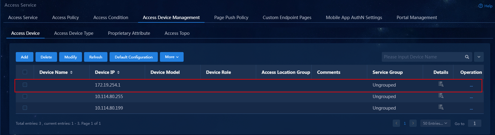
3. Click the Access Device Management > Access Device tab.
Figure 3 Access device configuration page
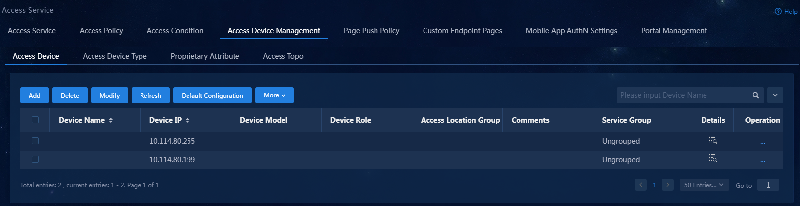
4. Click Add.
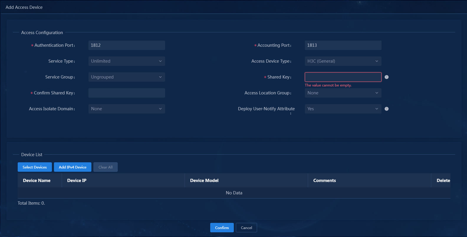
Figure 4 Adding an access device
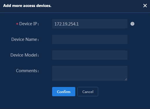
5. Click Add IPv4 Device in the Device List area. In the window that opens, enter the IP address of the access device in the Device IP field, and then click Confirm. Follow the following restrictions and guidelines when adding the access device:
¡ If the RADIUS scheme contains a NAS IP specified by using the nas ip command for the access device, specify that IP address on the EIA server.
¡ If the RADIUS scheme does not contain a NAS IP, specify the IP address of the Layer 3 Ethernet interface or VLAN interface that connects the access device to the EIA server.
Figure 5 Manually adding an access device
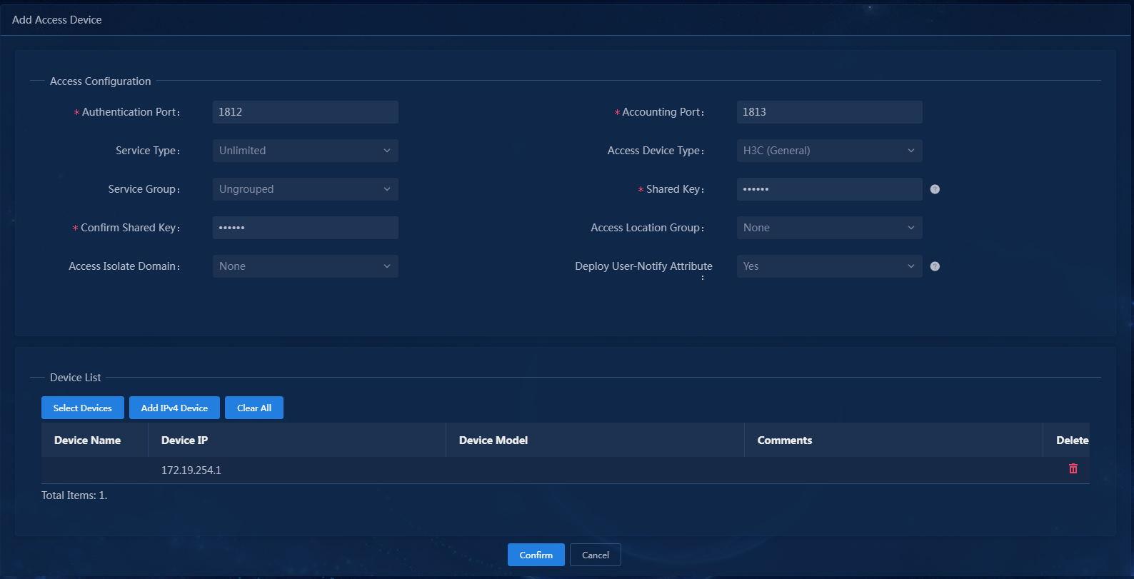
6. Configure the following common parameters:
¡ Authentication Port: Specify a port number for EIA to listen for RADIUS authentication packets. The authentication port must be the same as that specified in the RADIUS scheme on the access device. By default, the authentication port is 1812 on the EIA server and the access device.
¡ Accounting Port: Specify a port for EIA to listen for RADIUS accounting packets. The accounting port must be the same as that specified in the RADIUS scheme on the access device. By default, the accounting port is 1813 on the EIA server and the access device.
|
|
IMPORTANT: You must use the EIA server to provide both authentication and accounting services. You cannot use the EIA server as the authentication server and another server as the accounting server. |
¡ Shared Key/Confirm Shared Key: Specify a shared key and confirm it. The access device and the EIA server use the shared key to validate each other. The shared key must be the same as that configured in the RADIUS scheme on the access device. You only need to enter the shared key once if you selected Plaintext for the Displays Key in field in system parameter settings on the Automation > User > Service Parameters > Access Parameters > System Settings page.
¡ Use the default settings for other parameters.
In this example, you only need to enter shared key export and confirm the key, as shown in Figure 6.
Figure 6 Configuring common parameters
7. Click Confirm. Verify that the access device has been added to the access device list.
Figure 7 Verifying that the access device has been added
Adding an access policy
This example adds an access policy that does not contain any user-defined access control settings.
To add an access policy:
1. On the top navigation bar, click the Automation tab.
2. From the navigation pane, select User > Access Service.
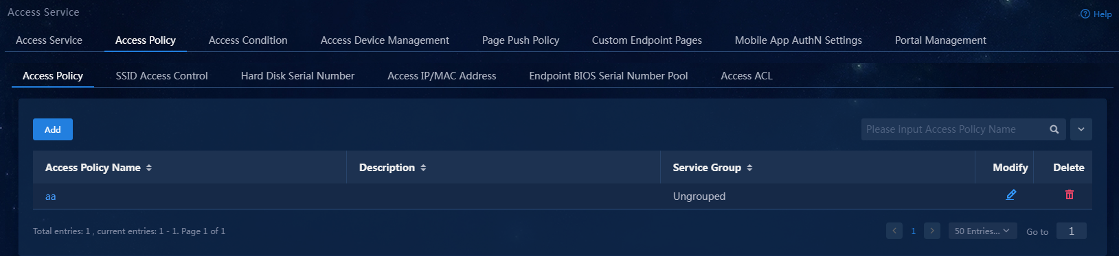
3. Click the Access Policy > Access Policy tab.
Figure 8 Access policy management page
4. Click Add. On the page that opens, configure the access policy as needed. For the purpose of this example, enter the access policy name, and use the default settings for other parameters.
Figure 9 Adding an access policy
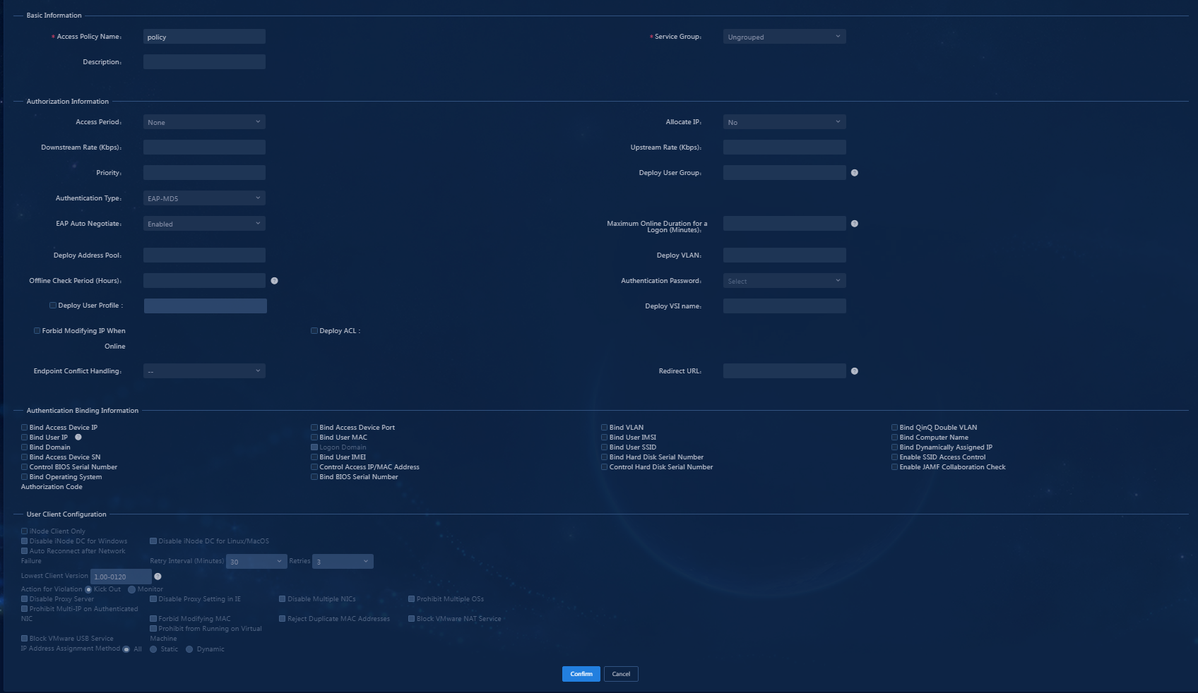
|
|
NOTE: To deploy authorization information, make sure the attributes are supported on the device. For the authentication binding information to take effect, you must configure the corresponding information in the RADIUS attributes on the device. In this example, you do not need to deploy authorization information. The default settings apply. |
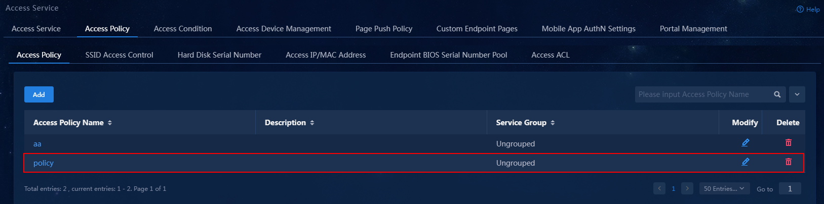
5. Click Confirm. On the access policy management page, verify that the access policy has been added to the access policy list.
Figure 10 Verifying that the access policy has been added
Adding an access service
An access service is a collection of policies for user authentication and authorization. This example adds a simple access service that does not contain any access control settings.
To add an access service:
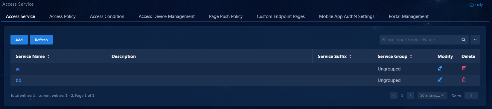
1. On the top navigation bar, click Automation. From the navigation pane, select User > Access Service.
Figure 11 Access service management page
2. Click Add.
Figure 12 Adding an access service
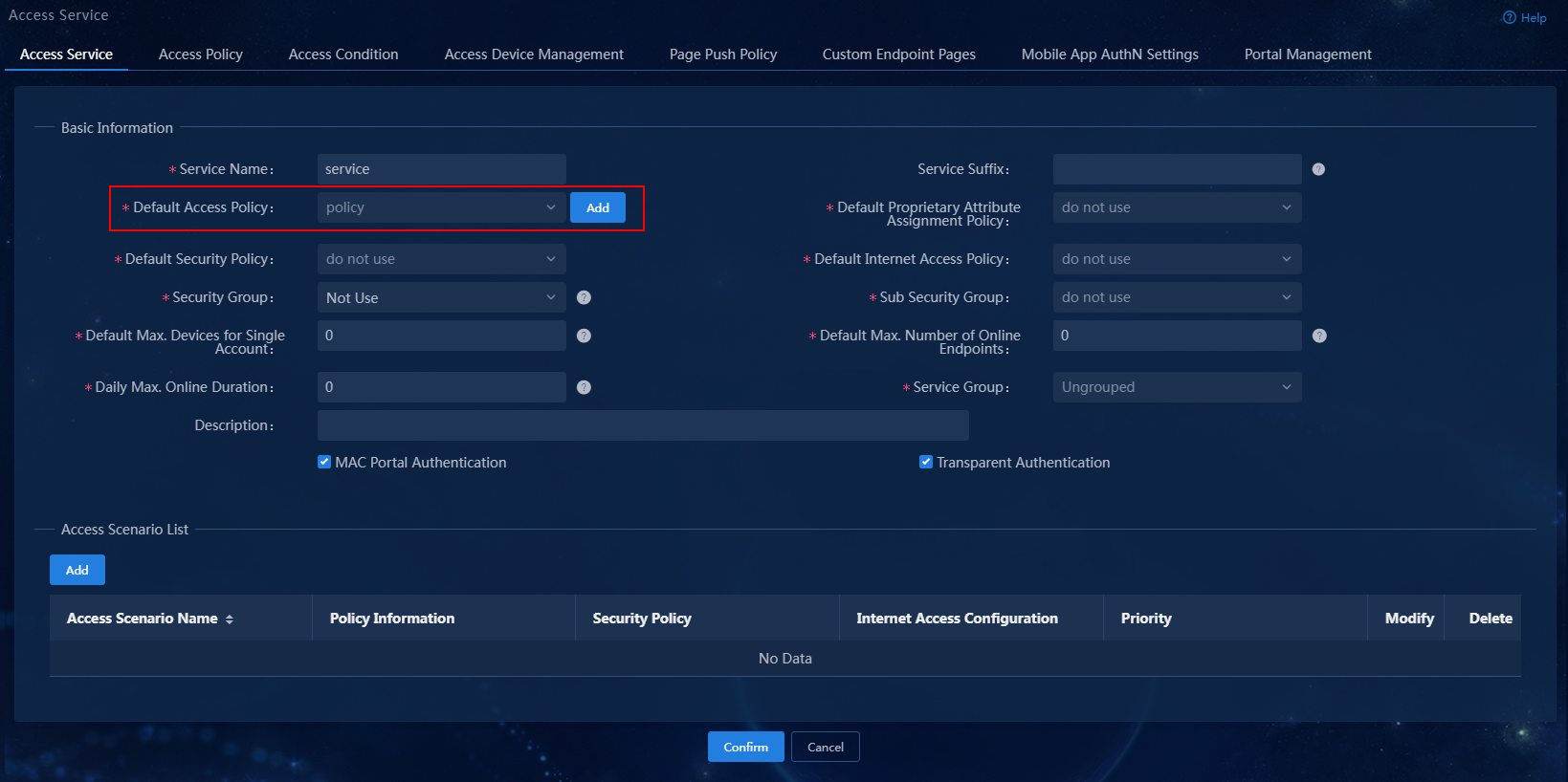
3. Configure the following parameters:
¡ Service Name: Enter a service name. Make sure the name is unique on the EIA server.
¡ Service Suffix: Enter a service suffix, which identifies the name of the domain to be used for user authentication. The service suffix, authentication username, authentication domain, and the device's RADIUS scheme command are closely related to each other. For more information about the matrix of these elements, see Table 1.
¡ Default Access Policy: Specify an access policy as the default access policy.
¡ Security group: Select a security group.
¡ Sub Security group: Select a sub security group.
¡ Default Proprietary Attribute Assignment Policy: Specify the default proprietary attribute assignment policy. If a user using the service does not match an access device group when the user accesses the network, the system deploys proprietary attributes to the access device according to the configuration of the default proprietary attribute assignment policy.
¡ Default Max. Devices for Single Account: Specify the number of endpoints to be bound to the same user account in access scenarios that are not included in the service. This field is available only when the EIP component is deployed.
EIA checks the maximum number of bound endpoint devices for a single account in the following order:
- Matched access scenario: Checks the number of bound endpoint devices against the maximum number limit specified in the scenario. If the number reaches the limit, EIA denies the user authentication.
- Scenarios in all services: Checks the number of bound endpoint devices in scenarios of all assigned services for the account. If the number reaches the value of Max. Devices for Single Account specified in user endpoint settings on the Automation > User > Service Parameters > Access Parameters > System Settings page, EIA denies the user authentication.
¡ Default Max. Number of Online Endpoints: Specify the maximum number of online endpoints using the same user account in access scenarios that are not included in the service.
¡ Daily Max. Online Duration: Total duration in a day that an account can access the network by using the service. When the limit is reached, the account is forced offline and is unable to access the network in the day. This parameter is an integer in the range of 0 to 1440 minutes. A value of 0 means not limited.
¡ Description: Enter a description for the access service.
|
Authentication username |
Authentication domain |
Device's RADIUS scheme command |
Service suffix on EIA |
|
X@Y |
Y |
user-name-format with-domain |
Y |
|
user-name-format without-domain |
No suffix |
||
|
X |
[Default Domain] Default domain on the device |
user-name-format with-domain |
[Default Domain] |
|
user-name-format without-domain |
No suffix |
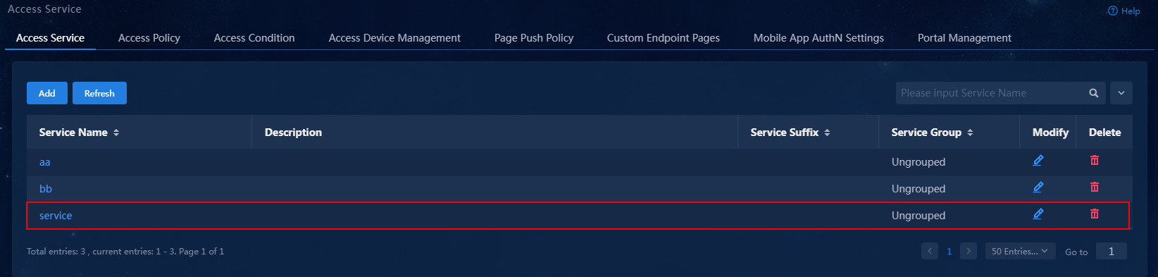
4. Click Confirm. On the service management page, verify that the access service has been added to the access service list.
Figure 13 Verifying that the access service has been added
Adding a mute terminal user
1. On the top navigation bar, click Automation.
2. From the left navigation pane, select User > Access User.
3. Click the Mute Terminal User Config Profile tab.
Figure 14 Mute terminal user config profiles
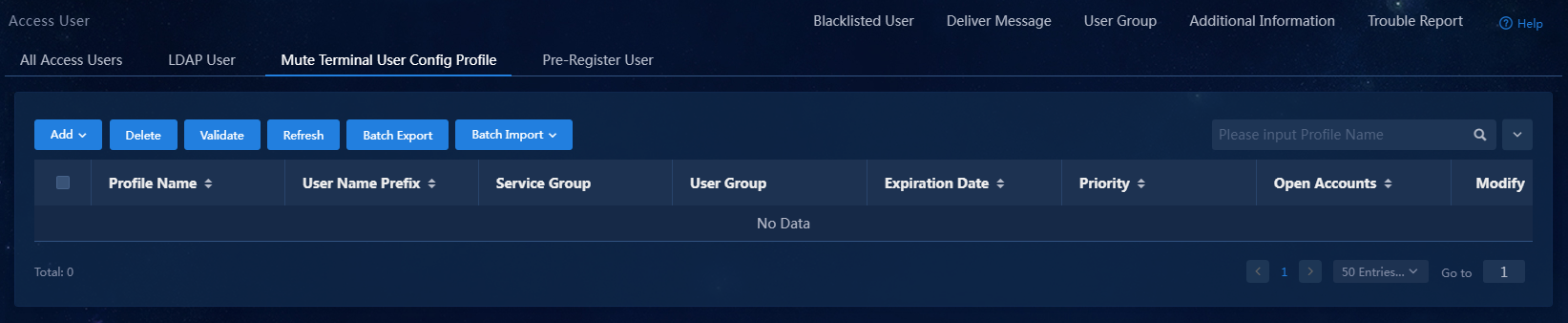
4. Click Add and select an option from the popup menu. In this example, By MAC Range is selected.
Figure 15 Adding mute terminal users
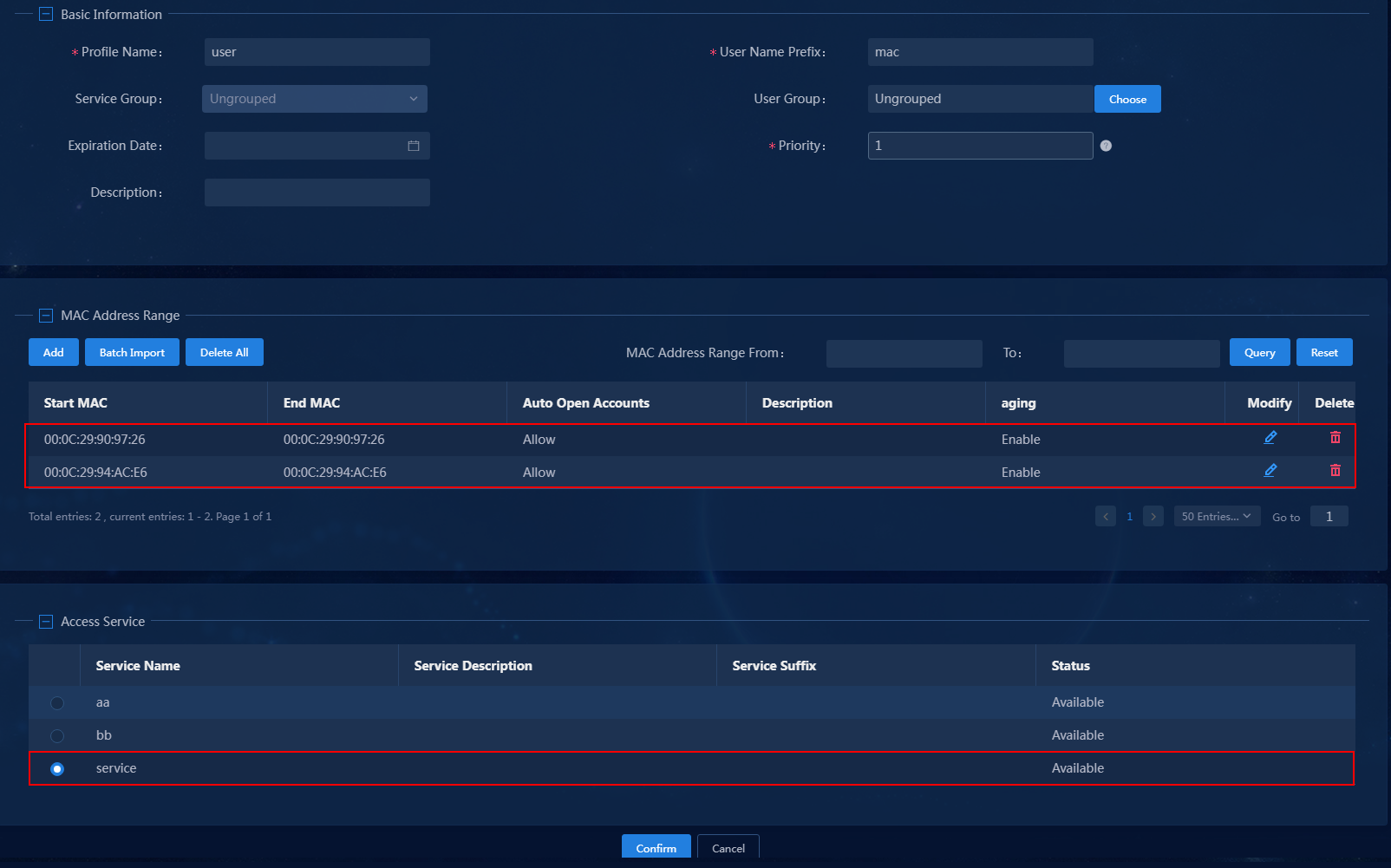
5. In the MAC Address Range area, add a MAC address range or batch import the MAC addresses for mute terminals. In the Access Service area, select the access service added in "Adding an access service."
6. Click Confirm.
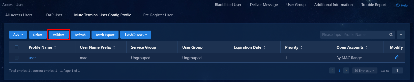
7. Click Validate to have the configuration take effect.
Figure 16 Validating the configuration
Configuring user onboarding
1. Configure an endpoint user to come online.
2. On the top navigation bar, click Monitor. From the navigation pane, select Monitor List > Online User. On the Local tab that opens, view the information about online local users, including endpoint device information.
Configuring EPS and EIA collaboration
To use EPS and EIA collaboration to control access for detected endpoints, you must configure service parameters on EPS. To do this, click Automation on the top navigation bar, and select Endpoint Business > EPS Management > Service Param from the navigation pane.
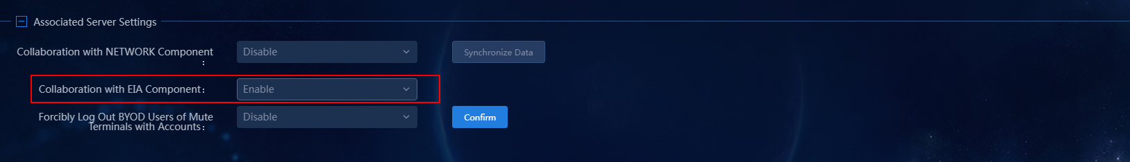
Configuring associated server settings
In the Associated Server Settings area, select Enable in the Collaboration with EIA Component field.
Figure 17 Configuring associated server settings
Configuring blacklist settings
In the Blacklist Parameters area, select EIA in the Add to Blacklist Through field, select Security First in the Service Scenario field, and select Enable in the Automatically Add Incompliant Endpoints to Blacklist field.
Figure 18 Configuring blacklist settings
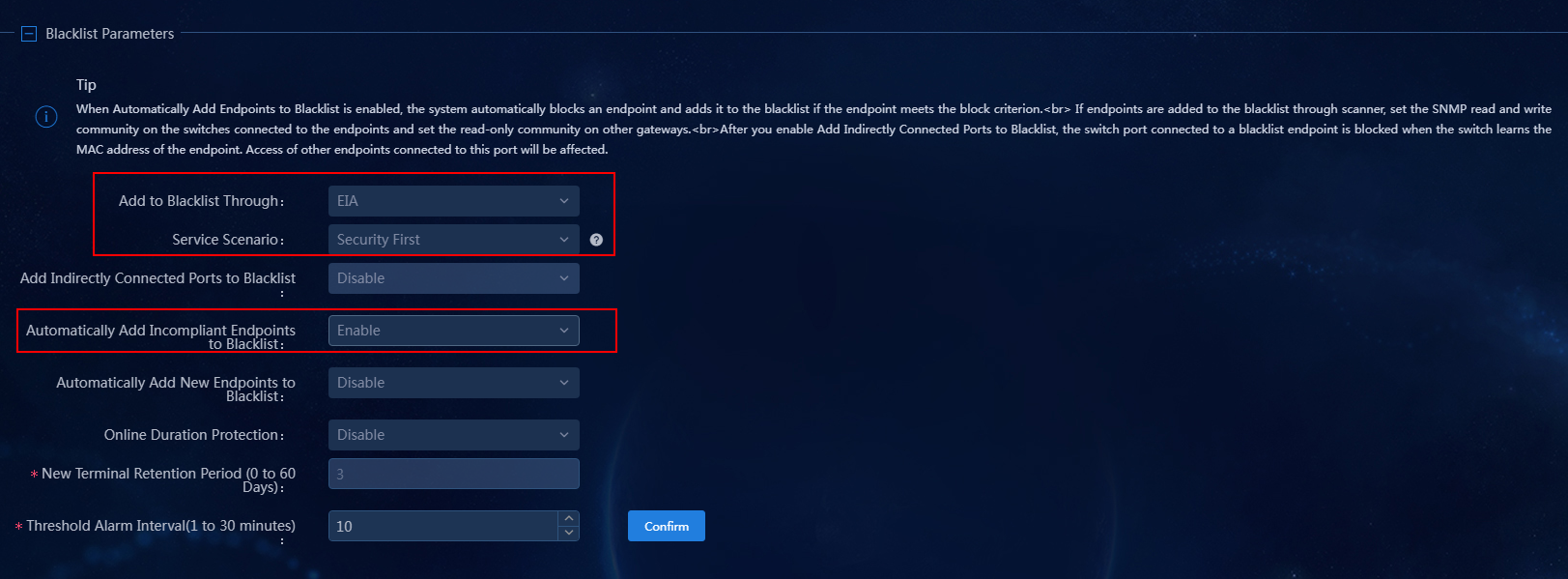
Blacklist parameters
· Add to Blacklist Through: Select a method of adding endpoints to the blacklist.
¡ Scanner: EPS assigns information about ports through which endpoints access the switch, and the scanner blocks access ports.
¡ EIA: EIA forces endpoint users to go offline and adds them to the blacklist. To use this feature, you must enable the associated server and enable collaboration with EIA.
¡ Security Gateway: EPS collaborates with security gateways to remove endpoints from the authentication whitelists of the security gateways.
· Service Scenario: Select a scenario for adding endpoints to the blacklist. The following options are supported:
¡ Service First: Supports only manually adding endpoints to the blacklist. This option is selected by default.
¡ Security First: Supports specifying criteria for automatically adding endpoints to the blacklist.
· Automatically Add Incompliant Endpoints to Blacklist: After you enable this option, the system immediately forces users on scanned incompliant endpoints to go offline and adds the endpoints to the blacklist.
Verifying the configuration
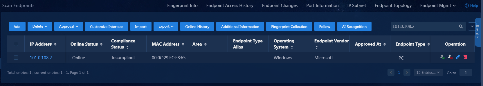
Manually setting an endpoint to incompliant
1. On EPS, navigate to the Automation > Endpoint Business > EPS Management > Scan Config > Scanner Mgmt page, and click Scan for the scanner. After the scanner scans the device information, navigate to the Monitor > Monitor List > Endpoint > Scan Endpoints page, and click Set to Incompliant in the Operation column for the target endpoint.
Figure 19 Setting an endpoint to incompliant
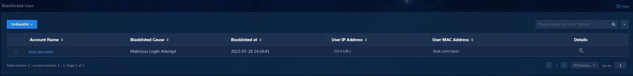
2. On EIA, verify that the endpoint user has been added to the blacklisted user list.
An endpoint will be added to the blacklisted user list of EIA automatically and forced to go offline by EPS and EIA collaboration, if the following conditions are met:
¡ You have selected the EIA option and configured the Automatically Add Incompliant Endpoints to Blacklist field on service parameters of EPS.
¡ You have approved the endpoint to be incompliant on EPS.
Figure 20 Verifying that the endpoint has been added to blacklist
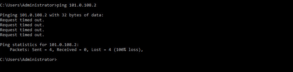
3. After the endpoint goes offline, its status changes from online to offline in the next connectivity check. Verify that the endpoint cannot be pinged.
Figure 21 Failed ping test to the offline endpoint
Configuring endpoint impersonation for access
Manually setting the endpoint to compliant for baseline information generation
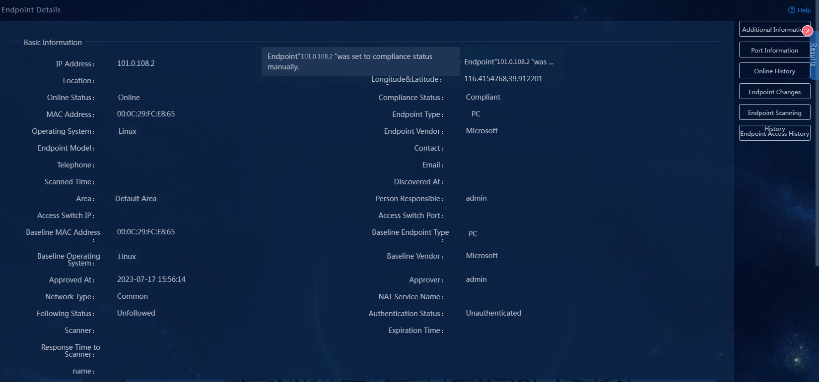
On EPS, navigate to the Automation > Endpoint Business > EPS Management > Scan Config > Scanner Mgmt page, and click Scan for the scanner. After the scanner scans the device information, navigate to the Monitor > Monitor List > Endpoint > Scan Endpoints page, and click Set to Compliant in the Operation column for the target endpoint.
The system will generate the baseline information about the endpoint. To view the baseline information, click the IP address of the endpoint on the Monitor > Monitor List > Endpoint > Scan Endpoints page.
Figure 22 Endpoint information
Configuring endpoint impersonation
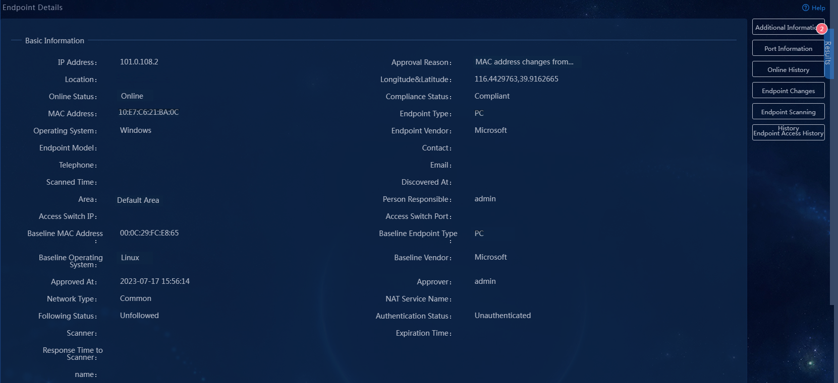
The scanner automatically scans endpoints as scheduled. When the scanner detected that the endpoint's endpoint type and other information have changed, the endpoint will be added to the blacklist of EIA automatically and forced to go offline by EPS-EIA collaboration. After the endpoint goes offline, its status changes from online to offline in the next connectivity check. Verify that the endpoint cannot be pinged.
Figure 23 Incompliant endpoint
Using a compliant endpoint to come online again
Replace the incompliant endpoint device with a compliant one and manually approve the endpoint to be a compliant endpoint. EPS will collaborate with EIA to have the endpoint come online again. The endpoint's status will change from offline to online in the next connectivity check.
