- Released At: 09-12-2024
- Page Views:
- Downloads:
- Related Documents
-
|
|
|
H3C Transparent Portal Authentication (IPv4) with EIA Configuration Examples |
|
|
|
|
Software version: EIA (E0215P06)
Document version: 5W103-20240226
Copyright © 2024 New H3C Technologies Co., Ltd. All rights reserved.
No part of this manual may be reproduced or transmitted in any form or by any means without prior written consent of New H3C Technologies Co., Ltd.
Except for the trademarks of New H3C Technologies Co., Ltd., any trademarks that may be mentioned in this document are the property of their respective owners.
The information in this document is subject to change without notice.
Introduction
The following information provides an example of configuring an IPv4 transparent portal authentication (also called portal MAC-trigger authentication) for user identity authentication with the EIA server. Transparent portal authentication is more convenient than common portal authentication methods. It is applicable to scenarios where users access the network frequently. A user only needs to enter the username and password once and can pass subsequent authentication without entering the username and password repeatedly.
Feature usage guidelines
Application scenarios
The following information applies to enterprise networks or campus networks requiring portal authentication.
Prerequisites
The access devices support portal protocol.
Example: Configuring IPv4 transparent portal authentication
Network configuration
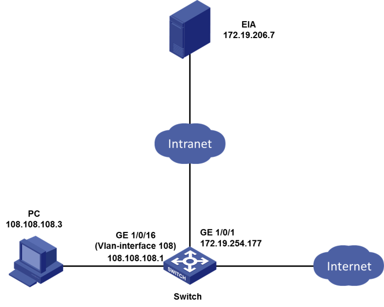
As shown in Figure 1, deploy the EIA as a portal authentication server to authenticate users who try to access the network resources.
In this example, the IP address of the EIA server is 172.19.206.7, and the IP address of VLAN-interface 108 where the access device user-side interface GigabitEthernet 1/0/16 resides is 108.108.108.1. The user has a PC installed with Windows. The IP address of the PC is 108.108.108.3.
Restrictions and guidelines
In a cluster deployment, specify the northbound service virtual IP as the IP address of the EIA server. Do not specify the node IP address of the EIA server.
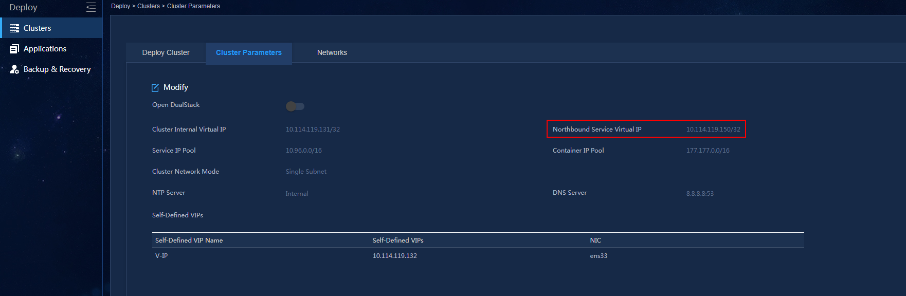
To identify the northbound service virtual IP of the EIA server in a cluster deployment:
1. Enter https://ip_address:8443/matrix/ui in the address bar of the browser to open the Matrix page. ip_address represents the northbound service virtual IP or node IP address.
2. On the top navigation bar, click DEPLOY.
3. From the left navigation pane, select Clusters.
4. Click the Cluster Parameters tab. Use the IP address in the Northbound Service Virtual IP field as the IP address of the EIA server.
|
|
NOTE: The northbound service virtual IP (10.114.119.150) in the screenshot is for illustration only. It differs from the one used in this example. |
Figure 2 Viewing IP address of the EIA server
Software versions used
This configuration example was created and verified on EIA (E0215P06) and access device H3C S5820V2-54QS-GE.
Procedures
Configuring the EIA server
Configure the following items on the EIA server:
· Access device.
· Access policy.
· Access service.
· Access user.
· Portal service.
· System settings related to user endpoints.
Adding an access device
You must add an access device to the EIA server before the EIA server can work with the access device for authentication.
To add an access device to the EIA server:
1. On the top navigation bar, click Automation.
2. From the left navigation pane, select User > Access Service, and then click the Access Device Management tab.
Figure 3 Access device configuration page
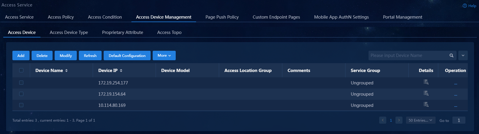
3. On the Access Device tab, click Add.
Figure 4 Adding the access device
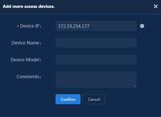
4. Click Add IPv4 Device. In the window that opens, enter the IP address of the access device in the Device IP field, and then click Confirm.
When you specify the IP address of the access device, examine the applicable RADIUS scheme on the access device to identify the IP address to specify.
¡ If the RADIUS scheme contains a NAS IP specified by using the nas-ip command for the access device, specify that IP address on the EIA server.
¡ If the RADIUS scheme does not contain a NAS IP, specify the IP address of the Layer 3 Ethernet interface or VLAN interface that connects the access device to the EIA server.
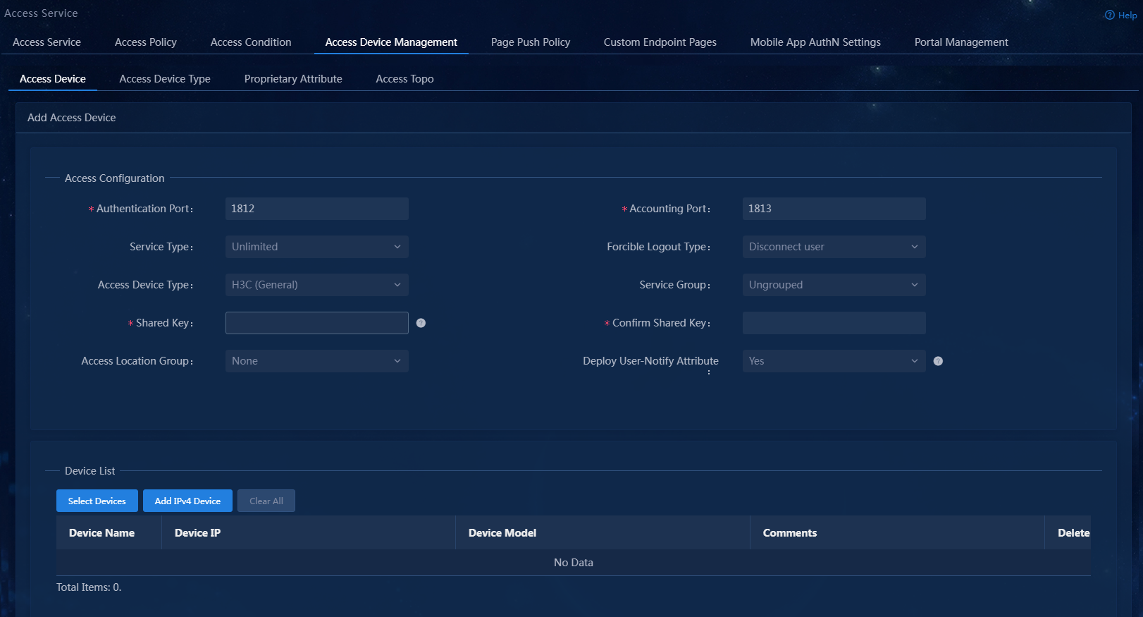
Figure 5 Manually adding the access device
5. Configure the following common parameters:
¡ Authentication Port: Specify the RADIUS authentication service port on the EIA server. It must be the same as that specified on the access device. Typically, use the default service port (1812).
¡ Accounting Port: Specify the RADIUS accounting service port on the EIA server. It must be the same as that specified on the access device. Typically, use the default service port 1813.
|
|
IMPORTANT: You must use the EIA server to provide both authentication and accounting services. You cannot use the EIA server as the authentication server and another server as the accounting server. |
¡ Shared Key/Confirm Shared Key: Enter a shared key in the Shared Key field. If the system is configured to display keys in ciphertext, you must enter the key again in the Confirm Shared Key field for confirmation.
The shared key is used for secure communication between the server and the access device.
The shared key specified on the EIA server must be the same as that specified on the access device.
You only need to enter the shared key once if you selected Plaintext in the Displays Key in field on the Automation > User > Service Parameters > Access Parameters > System Settings page.
¡ Use the default settings for other parameters.
Figure 6 Configuring common parameters
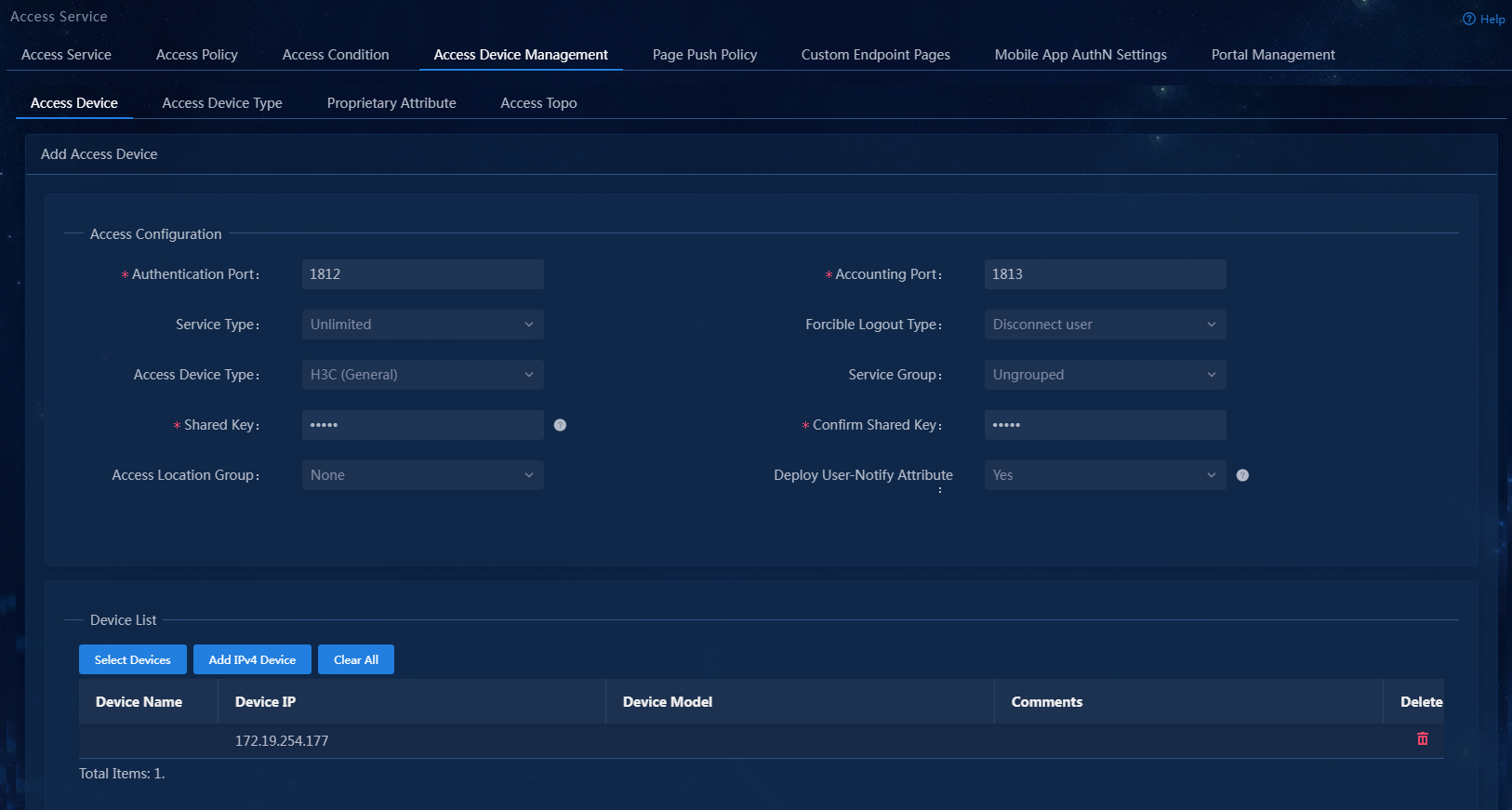
6. Click Confirm. Verify that the access device has been added to the access device list.
Figure 7 Verifying that the access device has been added

Adding an access policy
This example adds an access policy that does not contain any user-defined access control settings.
1. On the top navigation bar, click Automation.
2. From the left navigation pane, select User > Access Service, and then click the Access Policy tab.
Figure 8 Access policy configuration page
3. Click Add. On the page that opens, configure the access policy as needed. For the purpose of this example, enter the access policy name, and use the default settings for other parameters.
Figure 9 Adding the access policy
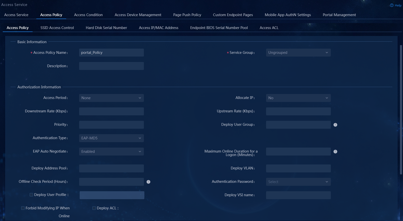
Access policy parameters
¡ Access Period: Select an access period policy from the list. A user using the access policy can access the network only in the time ranges defined in the access period policy.
¡ Allocate IP: Specify whether to assign IP addresses to users.
¡ Upstream Rate (Kbps)/Downstream Rate (Kbps): Specify the maximum upstream rate and downstream rate for users that match the access policy.
¡ Priority: Specify the traffic priority during network congestion. A smaller value indicates a higher priority. Select a priority value from the priority values supported by the device. An invalid value might result in failures of endpoint users to access the network.
¡ Authentication Type/Subtype: Select an EAP authentication type. During EAP authentication, the RADIUS server deploys this EAP authentication type to the client. Options include EAP-MD5, EAP-TLS, EAP-TTLS, and EAP-PEAP. If you select the EAP-TTLS or EAP-PEAP authentication type, select EAP-MSCHAPv2, EAP-MD5, or EAP-GTC as the subtype.
- EAP-MD5: CHAP-based EAP authentication.
- EAP-TLS: Certificate-based identity authentication, which uses the TLS protocol to implement identity authentication and requires PKI for certificate management. The server and client use certificates for identity authentication. If authentication succeeds, the two sides negotiate a shared key, session ID, and cipher suite (encryption, compression, and data integrity check) to set up a secure and reliable communication channel. EAP-TLS uses the session ID for fast reauthentication, which greatly simplifies the authentication process. It also supports fragmentation of large TLS packets.
- EAP-TTLS: Certificate-based identity authentication, which initiates subauthentication within the security channel set up by TLS authentication between the client and EIA. The authentication method protects the user identity and the EAP authentication negotiation process. Subauthentication types include EAP or non-EAP authentication. EAP authentication can be EAP-MSCHAPv2, EAP-MD5, or EAP-GTC. Non-EAP authentication can be MSCHAPv2 or PAP. If you select the EAP-TTLS authentication type, you must select an EAP subtype on EIA. However, in actual authentication, an endpoint can use a non-EAP subtype (PAP, for example) even if an EAP subtype is configured on EIA.
- EAP-PEAP: Certificate-based identity authentication, which initiates EAP authentication within the security channel set up by TLS authentication between the client and EIA. The authentication method protects the user identity and the EAP authentication negotiation process. EAP authentication can be EAP-MSCHAPv2, EAP-MD5, or EAP-GTC.
¡ EAP Auto Negotiate: Specify whether to enable automatic negotiation of EAP authentication types when the EAP authentication types specified on the client and EIA are different. With this feature enabled, EIA permits the client's authentication request without considering the EAP type configured on the client. With this feature disabled, EIA rejects the client's authentication request if the EAP authentication types specified on the client and EIA are different.
¡ Maximum Online Duration for a Logon (Minutes): Specify the maximum duration an authenticated user that uses the access policy can be online, in minutes. The value is an integer in the range of 1 to 1440. If you leave this field empty, the online duration is not limited. If you specify a value and the online duration of an access user exceeds the specified value, EIA logs off the user.
¡ Deploy VLAN: Specify a VLAN ID or name for deployment to users. After passing authentication, users can access resources in the specified VLAN only. On the access device, configure the VLAN assignment mode as integer or string type accordingly:
- If the type of the access device is H3C (General), HUAWEI (General), HP (Comware), or 3COM (General), you can enter a VLAN ID or VLAN name. EIA takes any integer in the range of 1 to 4094 as an integer-type VLAN ID and deploys it to the access device. Any other character string is taken as a string-type VLAN name and deployed to the access device.
- If the access device is none of the previous types, EIA always deploys the entered value to the access device as a string-type VLAN name.
¡ Deploy Address Pool: Enter an address pool name to be deployed to the access device for IP address assignment to users. For successful address assignment, make sure an address pool with the same name exists on the access device.
¡ Deploy User Profile: Specify the name of the user profile for deployment to the device to perform user-based QoS functions. This feature takes effect only when the user profile to be deployed has been configured on the device.
¡ Deploy User Group: Specify the name of the user group to which the users belong after they pass authentication. You can enter multiple user groups, separated by semi-colon (;). This feature takes effect only when EIA works with an SSL VPN device or collaborates with ACG 1000.
¡ Deploy ACL: Specify the ACL for deployment to access users.
¡ Offline Check Period (Hours): Specify the offline check interval for mute terminals, in hours. The value must be an integer in the range of 0 to 596523. After a mute terminal passes authentication, EIA deploys the configuration to the device and the device checks whether the mute terminal is offline at the specified periods. If no packet is received from a mute terminal within a period, the device terminates the connection with the mute terminal and sends a user offline notification to the RADIUS server. If you leave this field empty or set the value to 0, offline check will not be performed.
¡ Authentication Binding Information: EIA cooperates with the access device to check the binding information for each user account to be authenticated, including the IP address, port, VLAN, QinQ double VLAN, and SN of the access device, and the IP address, MAC address, IMSI, IMEI, wireless user SSID and the hard disk serial number of the user endpoint. The iNode client cooperates with the policy server to check the following binding information of the user: user IP address, MAC address, computer name, computer domain, logon domain and hard disk serial number. Among the binding items, user MAC address and IMSI are mutually exclusive and cannot be bound at the same time. You can configure binding information for an access policy and apply the access policy in an access service. If a user uses an access service that applies an access policy without binding information, auto learning is adopted. In this case, EIA binds the parameters used in the first login of a user. For example, if a user uses 10.100.10.10 for the first login through the service, the user must always use the IP address for future authentication.
- Control Hard Disk Serial Number: With this feature enabled, EIA checks the hard disk serial number of a user endpoint when the user attempts to come online. If the serial number is permitted or EIA cannot obtain the hard disk serial number, the user is allowed to come online. Otherwise, the access is denied. This feature must work with the iNode PC client.
- Enable SSID Access Control: When you enable this feature and set the SSID filter to Permit, EIA maintains an SSID allowlist. Users can access the network when they connect to an SSID on the SSID access control list. When you enable this feature and set the SSID filter to Deny, EIA maintains an SSID denylist. Users cannot access the network when they connect to an SSID on the SSID access control list. This feature must work with the iNode PC client. The client receives the SSID access control configuration from EIA and saves it to the PC. The configuration also applies to the Windows built-in 802.1X application.
|
|
NOTE: To deploy authorization information, make sure the attributes are supported on the device. For the authentication binding information to take effect, you must configure the corresponding information in the RADIUS attributes on the device. In this example, you do not need to deploy authorization information. The default settings apply. |
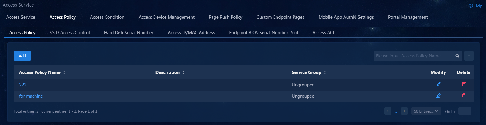
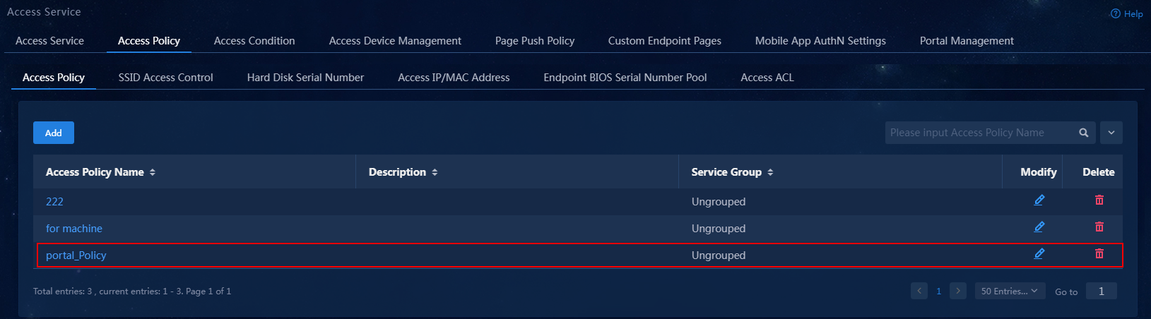
4. Click Confirm. Verify that the access policy has been added to the access policy list.
Figure 10 Verifying that the access policy has been added
Adding an access service
An access service is a collection of policies for user authentication and authorization. This example adds a simple access service that does not contain any access control settings.
To add an access service:
1. On the top navigation bar, click Automation.
2. From the left navigation pane, select User > Access Service to open the Access Service page.
Figure 11 Access service management page

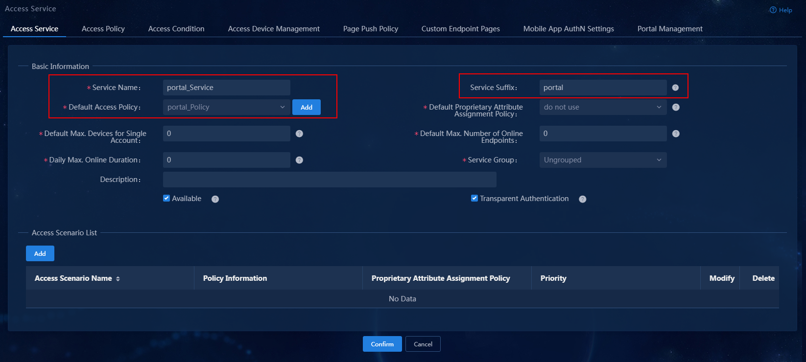
3. Click Add. On the page that opens, enter the service name and service suffix, specify the default access policy, and use the default settings for other parameters. In this example, service suffix portal is used.
Figure 12 Adding the access service
Access service parameters
¡ Service Name: Specify a service name. A service name uniquely identifies an access service in EIA. In this example, portal_Service is used.
¡ Service Suffix: Specify a service suffix. The service suffix, authentication username, authentication domain, and the device's RADIUS scheme command are closely related to each other. For more information about the matrix of these elements, see Table 1. In this example, service suffix portal is used.
¡ Default Access Policy: Specify an access policy as the default access policy. In this example, portal_Policy is used.
¡ Security Group: Specify a security group.
¡ Sub Security Group: Specify a security subgroup.
¡ Default Proprietary Attribute Assignment Policy: Specify the default proprietary attribute assignment policy. If a user using an access service does not match an access location group when accessing the network, EIA deploys proprietary attributes to the access device according to the specified default proprietary attribute assignment policy.
¡ Default Max. Devices for Single Account: Specify the maximum number of endpoints that can be bound to the access user when the user's access scenario matches none of the access scenarios in the service assigned to the user. This field is available only when the EIP component is deployed. EIA checks the maximum number of bound endpoint devices for a single account in the following order:
- Matched access scenario—Checks the number of bound endpoint devices against the maximum number limit specified in the scenario. If the number reaches the limit, EIA denies the user authentication.
- Scenarios in all services—Checks the number of bound endpoint devices in scenarios of all services assigned to the account. If the number reaches the value of Max. Devices for Single Account specified in user endpoint settings on the Automation > User > Service Parameters > Access Parameters > System Settings page, EIA denies the user authentication.
¡ Default Max. Number of Online Endpoints: Specify the maximum number of endpoints that can be simultaneously used for network access by the access user when the user's access scenario matches none of the access scenarios in the service assigned to the user.
¡ Daily Max. Online Duration: Specify the total duration in a day that an account can access the network by using the service. When the limit is reached, the account is forced offline and cannot access the network this day. The value is an integer in the range of 0 to 1440 minutes. A value of 0 means not limited.
¡ Description: Enter a brief description for the service.
|
Authentication Username |
Authentication Domain |
Device's RADIUS Scheme Command |
Service Suffix |
|
X@Y |
Y |
user-name-format with-domain |
Y |
|
user-name-format without-domain |
No suffix. |
||
|
X |
[Default Domain] |
user-name-format with-domain |
[Default Domain] |
|
user-name-format without-domain |
No suffix. |
4. Click Confirm. Verify that the access service has been added to the access service list.
Figure 13 Verifying that the access service has been added

Adding an access user
1. On the top navigation bar, click Automation.
2. From the left navigation pane, select User > Access User.
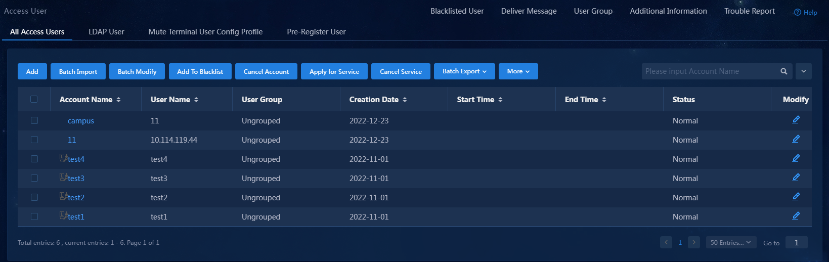
Figure 14 Access user configuration page
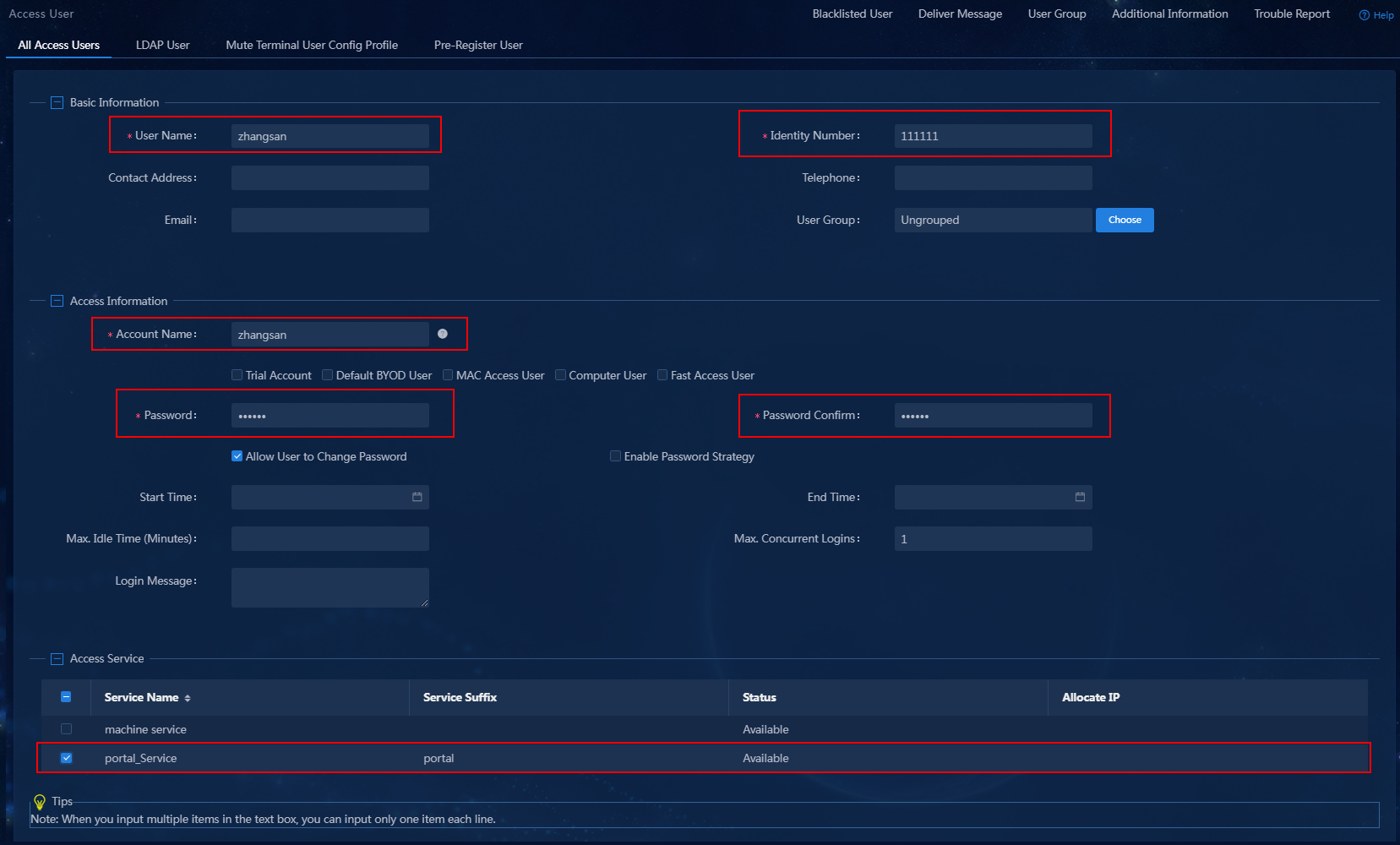
3. Click Add. On the page that opens, configure the access user parameters.
Figure 15 Adding an access user
Access user parameters
¡ User Name: Specify a username for the access user.
¡ Identity Number: Specify an identity number for the access user.
¡ Account Name: Specify an account name to uniquely identify the access user. The access user can use the account name to subscribe to and use services. The account name can contain a maximum of 200 characters and cannot include the TAB character or any of characters #+/?%&=*'@\"[]()<>`.
¡ Password/Password Confirm: Enter the password for authentication and enter the password again for confirmation.
¡ Access Service: Select an added access service.
¡ Use the default settings for other parameters.
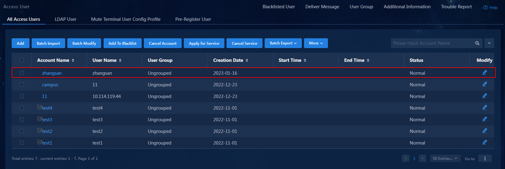
4. Click Confirm. Verify that the access user has been added to the access user list.
Figure 16 Verifying that the access user has been added
Configuring the portal service
Perform the following tasks to configure the portal service:
· Configuring a portal server.
· Configuring a portal IP group.
· Configuring a portal device.
Configuring a portal server
1. On the top navigation bar, click Automation.
2. From the left navigation pane, select User > Access Service, and then click the Portal Service tab.
Figure 17 Portal server configuration page
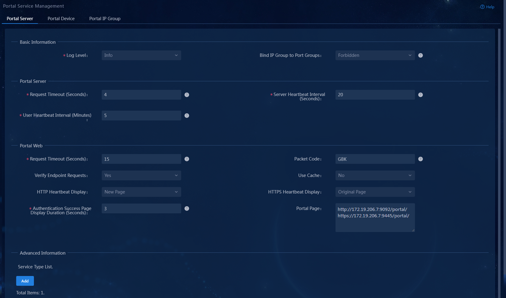
3. In the Advanced Information area, click Add next to Service Type List. On the page that opens, add a service type.
Figure 18 Adding a service type

Service type parameters
¡ Service Type ID: The device determines the authentication mode according to the ID of the selected service type. You can make appropriate setting here according to the configuration of the platform services and devices. Make sure the service type ID is the same as the service suffix of the added access service. In this example, portal is used.
¡ Service Type: A service type ID is used by the device. Users might not understand what a service type ID means. You must enter a service type that is understandable to users for the service type ID. Service types will be displayed on the portal login page for users to select. This field can neither be null nor be identical with any existing service type. You can configure a maximum of 64 service types.
4. Click Confirm. Verify that the service type has been added to the service type list.
Figure 19 Verifying that the service type has been added
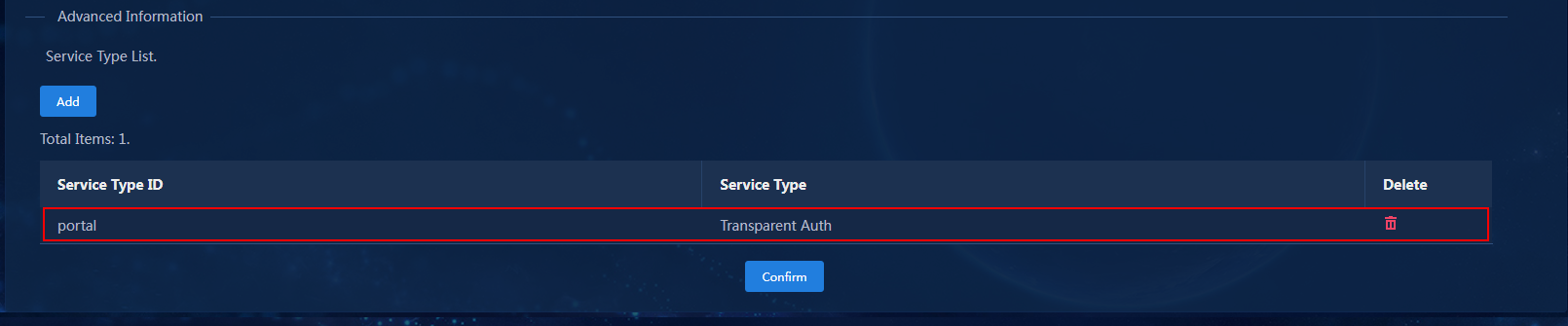
5. Click Confirm to complete portal server configuration.
Configuring a portal IP group
1. On the top navigation bar, click Automation.
2. From the left navigation pane, select User > Access Service, and then click Portal Service > Portal IP Group.
Figure 20 Portal IP group configuration page
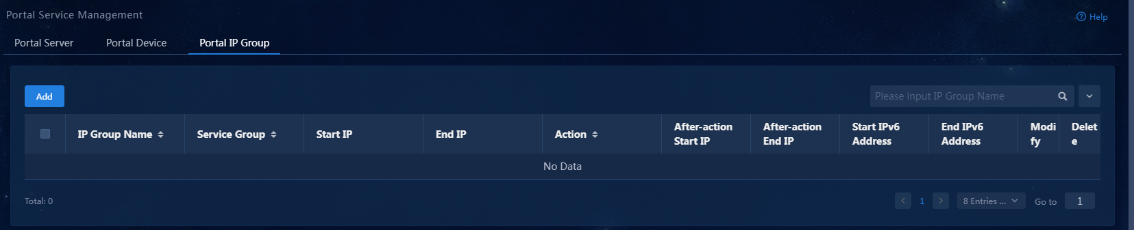
3. Click Add. On the page that opens, add an IP group.
Figure 21 Adding an IP group

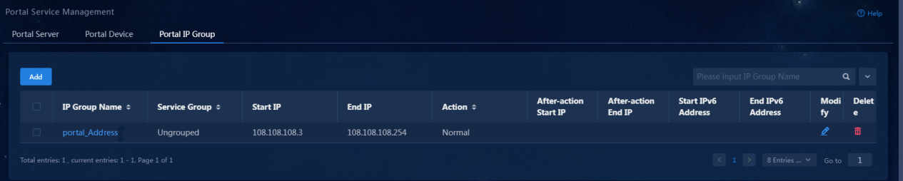
4. Enter the IP group name, start IP, and end IP. In this example, IP group name portal_Address is used. The system performs authentication on all endpoints in the address segment.
5. Click Confirm. Verify that the IP group has been added to the IP group list.
Figure 22 Verifying that the IP group has been added
Configuring a portal device
1. On the top navigation bar, click Automation.
2. From the left navigation pane, select User > Access Service, and then click Portal Service > Portal Device.
Figure 23 Portal device configuration page
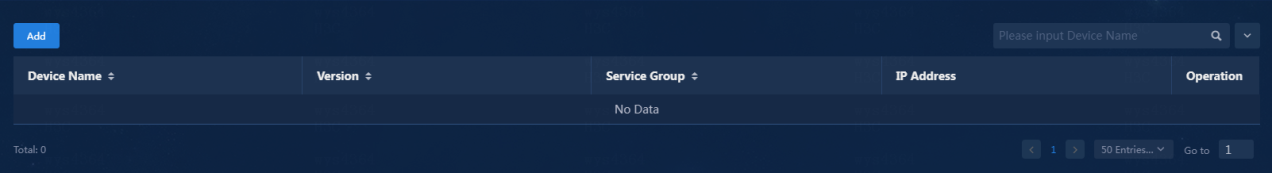
3. Click Add. On the page that opens, add a portal device.
Figure 24 Adding a portal device
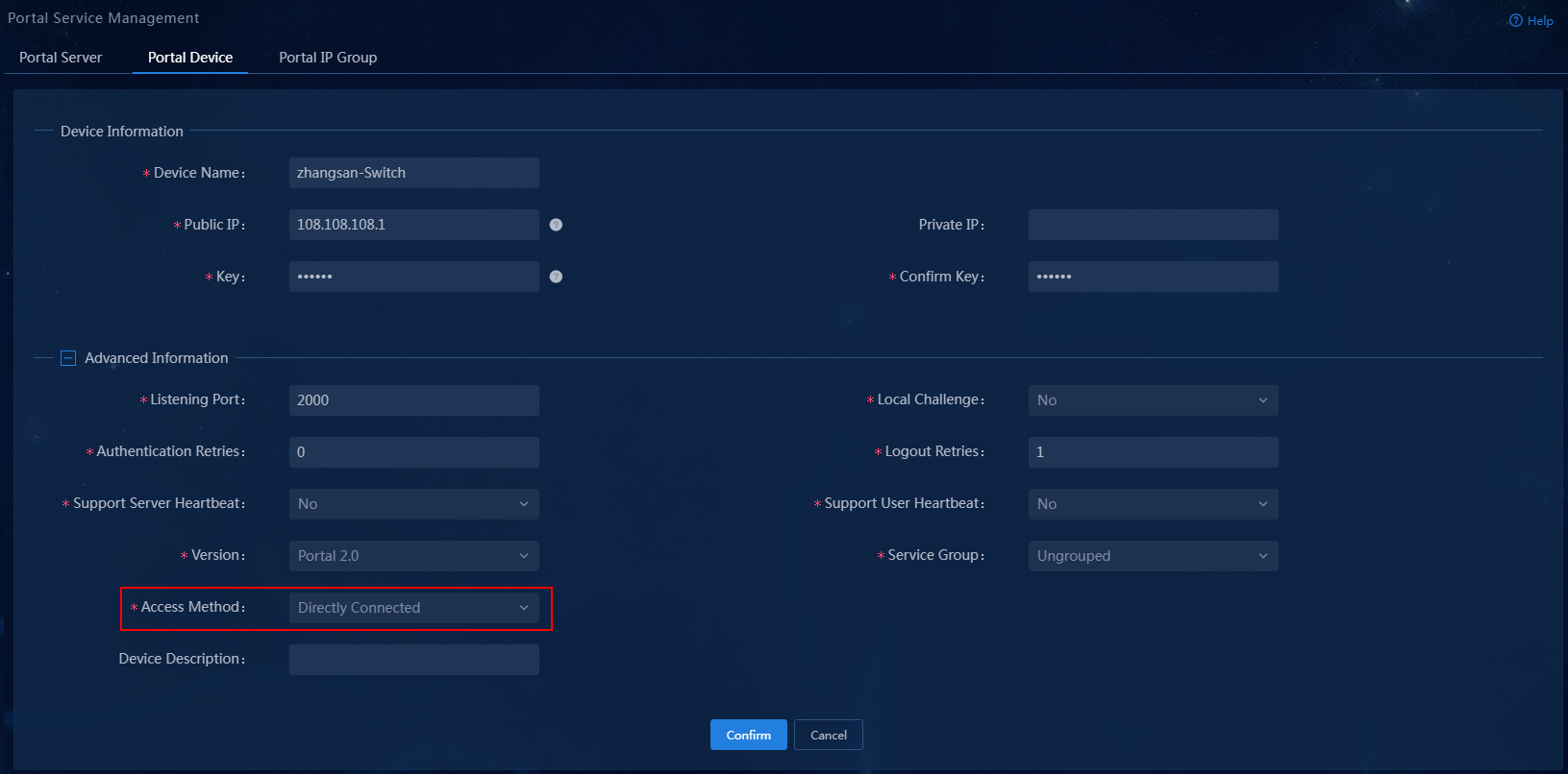
Portal device parameters
¡ Device Name: Name of the portal access device. In this example, zhangsan-Switch is used.
¡ Public IP: Public IP address of the access device.
¡ Key/Confirm Key: Enter the key for authentication and enter the key again for confirmation. The key must be identical with the configuration on the device. In this example, movie is used.
¡ Access method: Select the authentication mode used by the device. In this example, Directly Connected is used.
¡ Use the default settings for other parameters.
4. Click Confirm. Verify that the portal device has been added to the portal device list.
Figure 25 Verifying that the portal device has been added

5. Click the Port Group
icon ![]() in the Operation column for the device.
in the Operation column for the device.
Figure 26 Port group configuration page
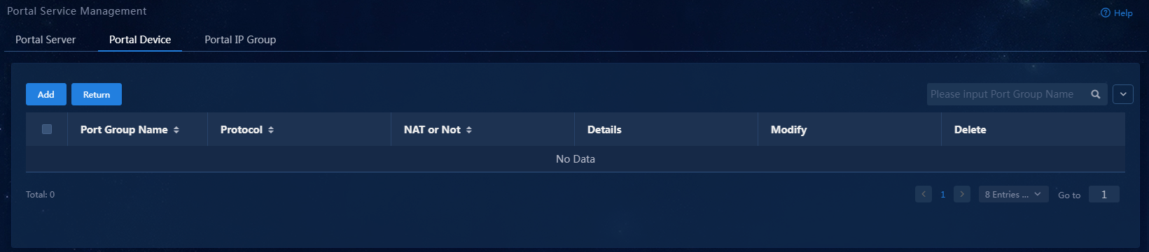
6. Click Add.
Figure 27 Adding a port group
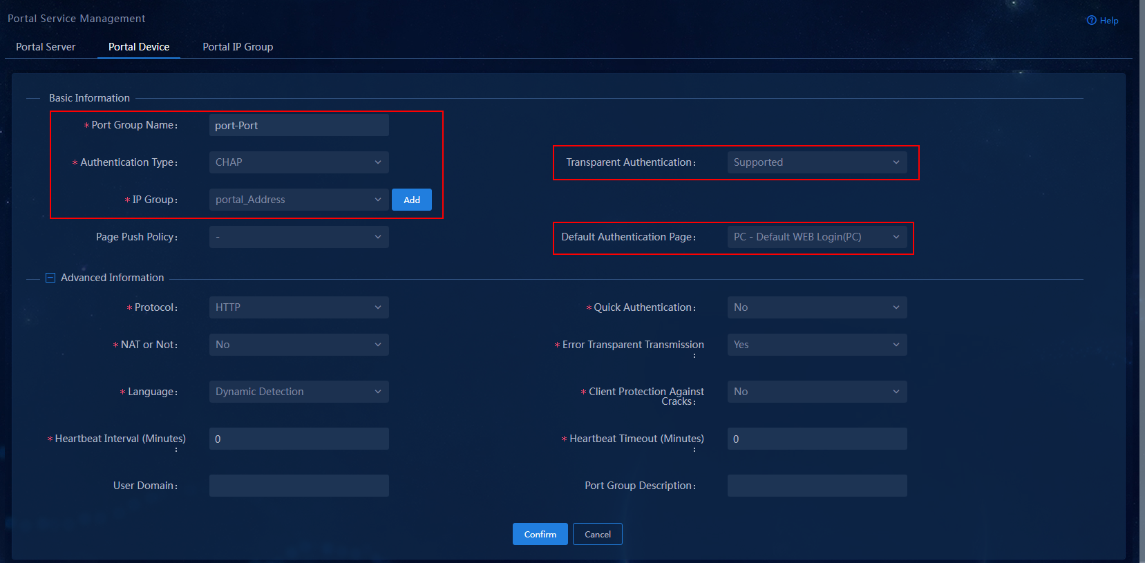
Port group parameters
¡ Port Group Name: Specify the port group name. In this example, port-Port is used.
¡ Authentication Type: Specify the authentication type. In this example, CHAP is used.
¡ IP Group: Specify the IG group. In this example, portal_Address is used.
¡ Transparent Authentication: Specify whether to support transparent portal authentication. In this example, select Supported from the list.
¡ Default Authentication Page: Specify the default authentication page. In this example, select PC - Default WEB Login(PC) from the list.
¡ Use the default settings for other parameters.
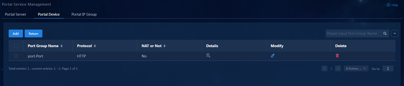
7. Click Confirm. Verify that the port group has been added to the port group list.
Figure 28 Verifying that the port group has been added
Configuring system settings
Configuring user endpoint settings
1. On the top navigation bar, click Automation.
2. From the left navigation pane, select User > Access Parameters.
3. On the System Settings page, click the Configure icon on the right side of parameter User Endpoint Settings. On the page that opens, select Enabled for the Transparent Authentication and Non-Smart Device Transparent Portal AuthN fields.
Figure 29 User endpoint settings configuration page

With Non-Smart Device Transparent Portal AuthN disabled, only smart device users can perform transparent portal authentication. Non-smart device users cannot perform transparent portal authentication but can perform other types of authentication.
Configuring endpoint aging policies
1. On the top navigation bar, click Automation.
2. From the left navigation pane, select User > Access Parameters.
3. On the System Settings page, click the Configure icon on the right side of parameter Endpoint Aging Policies. On the page that opens, add an aging policy or use the default aging policy as needed.
Figure 30 Endpoint aging policies configuration page
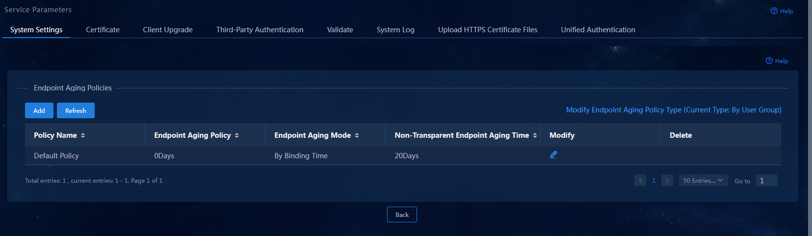
Endpoint aging policies parameters
¡ Transparent Endpoint Aging Time: Set the aging time in days or hours. When Day is selected, EIA detects the expired and offline endpoints at 00:00 every day. When Hour is selected, EIA deletes the offline endpoints immediately after they expire and go offline.
¡ Endpoint Aging Mode: An endpoint can be aged based on the binding time or idle time. Use this parameter together with parameter Transparent Endpoint Aging Time.
- When an endpoint is aged based on the binding time, EIA detects the endpoint if the endpoint goes offline and the time interval since the first transparent MAC authentication exceeds the specified aging time. To use the endpoint for network access again, the user must re-enter the account name and password for authentication.
- When an endpoint is aged based on the idle time, EIA deletes the MAC address of the authenticated endpoint that does not come online for the specified aging time. To use the endpoint for network access again, the user must re-enter the account name and password for authentication.
¡ Non-Transparent Endpoint Aging Time: Set the aging time in days or hours. When Day is selected, EIA detects the expired and offline endpoints at 00:00 every day. When Hour is selected, EIA deletes the offline endpoints immediately after they expire and go offline.
|
|
IMPORTANT: · Transparent authentication permits network access without re-entering the account name and password when the endpoint MAC address has been bound to the account name of the user. For security purposes, the system deletes the endpoint that exceeds the specified endpoint aging time after the endpoint goes offline. To use the endpoint for network access again, the user must re-enter the account name and password for authentication. · When the endpoint aging time is set to 0 days or hours, endpoint information never expires. |
Configuring the access device
Configure the access device to perform portal authentication on users to make sure only users who have passed the authentication can access the network resources.
Log in to the CLI of the access device, for example, through Telnet:
1. Enter system view.
<Device>system-view
System View: return to User View with Ctrl+Z.
2. Specify the RADIUS scheme:
# Create RADIUS scheme allpermit.
[Device]radius scheme allpermit
New Radius scheme
# Specify the EIA server at 172.19.206.7 as the primary authentication server and primary accounting server, and set the shared keys to movie in plaintext form for communication with the server. (Make sure the authentication port, accounting port, and shared keys are the same as that configured on EIA in "Adding an access device.")
[Device-radius-allpermit]primary authentication 172.19.206.7 1812
[Device-radius-allpermit]primary accounting 172.19.206.7 1813
[Device-radius-allpermit]key authentication simple movie
[Device-radius-allpermit]key accounting simple movie
# Include domain names in the usernames sent to the RADIUS server.
[Device-radius-allpermit]user-name-format with-domain
# Specify a NAS IP address for RADIUS packets.
[Device-radius-allpermit]nas-ip 172.19.254.177
[Device-radius-allpermit]quit
3. Create an ISP domain named portal, and configure the ISP domain to use RADIUS scheme allpermit for authentication, authorization, and accounting. (Make sure the domain name is the same as the service suffix configured on EIA in "Adding an access service.")
[Device]domain portal
[Device-isp-portal]authentication portal radius-scheme allpermit
[Device-isp-portal]authorization portal radius-scheme allpermit
[Device-isp-portal]accounting portal radius-scheme allpermit
[Device-isp-portal]quit
4. Configure the portal authentication server:
# Create portal authentication server myportal.
[Device]portal server myportal
New portal server added.
# Specify the IP address of the EIA server as the IP address of the portal authentication server, and set plaintext key movie as the shared key for communication with the portal authentication server. (Make sure the key is the same as that configured on EIA in "Configuring a portal device.")
[Device-portal-server-myportal]ip 172.19.206.7 key simple movie
[Device-portal-server-myportal]quit
5. Create portal Web server myportal, and specify a URL for the portal Web server. (Make sure the URL is the same as the http or https URL in the Portal Page field configured on EIA in "Configuring a portal server." You can view the portal server configurations on EIA in Figure 17.)
[Device]portal web-server myportal
New portal web-server added.
[Device-portal-websvr-myportal]url http://172.19.206.7:9092/portal
[Device-portal-websvr-myportal]quit
6. Create a MAC binding server named mtsp and specify the IP address of MAC binding server. (Make sure the IP address is the IP address of the EIA server and the key is the same as that configured on EIA in "Adding an access device.")
The MAC binding server records the MAC-to-account bindings of portal users for authentication. The account contains the portal authentication information of the user, including account name and password.
[Device]portal mac-trigger-server mtsp
[Device-portal-mac-trigger-server mtsp]ip 172.19.206.7 key simple movie
7. Assign GigabitEthernet 1/0/16 to VLAN 108 and set the link mode to bridge for GigabitEthernet 1/0/16.
[Device]interface GigabitEthernet 1/0/16
[Device-GigabitEthernet1/0/16]port access vlan 108
[Device-GigabitEthernet1/0/16]port link-mode bridge
8. Configure portal authentication:
# Assign an IP address to VLAN-interface 108, and enable direct portal authentication on VLAN-interface 108 where GigabitEthernet 1/0/16 resides.
[Device]interface Vlan-interface 108
[Device-Vlan-interface108]ip address 108.108.108.1 255.255.255.0
[Device-Vlan-interface108]portal enable method direct
# Specify portal Web server myportal and MAC binding server mtsp on VLAN-interface 108.
[Device-Vlan-interface108]portal apply web-server myportal
[Device-Vlan-interface108]portal apply mac-trigger-server mtsp
# Configure the BAS-IP as 108.108.108.1 for portal packets sent to the portal authentication server, and specify authentication domain portal on VLAN-interface 108. (Make sure the BAS-IP is the same as the public IP configured on EIA in "Configuring a portal device.")
[Device-Vlan-interface108]portal bas-ip 108.108.108.1
[Device-Vlan-interface108]portal domain portal
[Device-Vlan-interface108]quit
|
|
IMPORTANT: If firewalls exist in the network, make sure the UDP ports are open. |
Verifying the configuration
Verify that the user can pass portal authentication by entering the configured account name and password on the Web page. After the user goes offline and try to access network resources again, the user can access the network resources without entering the account name and password again.
1. Open a browser and enter any address in the address bar. The user is redirected to the portal authentication page.
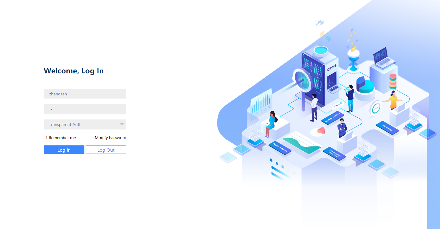
Figure 31 Portal authentication page

2. Enter the account name and password, and select service type Transparent Authentication.
Figure 32 Entering user information
3. Click Log In.
Figure 33 Portal authentication success page

The page prompts that the user logged in successfully after passing authentication. The user can access network resources.
4. Click offline. Verify that the user can access network resources without entering the account name and password again after going offline.
Figure 34 Successful logout