| Title | Size | Downloads |
|---|---|---|
| 07-H3C EAD Security Check Configuration Example-book.pdf | 2.46 MB |
- Table of Contents
- Related Documents
-
| Title | Size | Download |
|---|---|---|
| book | 2.46 MB |
H3C EAD Security Check
Configuration Example
Document version: 5W100-20240314
Product version: EAD (E6204)
Copyright © 2024 New H3C Technologies Co., Ltd. All rights reserved.
No part of this manual may be reproduced or transmitted in any form or by any means without prior written consent of New H3C Technologies Co., Ltd.
Except for the trademarks of New H3C Technologies Co., Ltd., any trademarks that may be mentioned in this document are the property of their respective owners.
The information in this document is subject to change without notice.
Contents
Adding an access service and applying the security policy
Adding an access user and applying for the service for the access user
Using the iNode client for verifying the security policy
Installing the iNode PC client with the 802.1X function
Introduction
Endpoint Admission Defense (EAD) is a multi-service security access management solution that integrates pre-authentication, in-process monitoring, post-audit, and service management. It ensures that users and their endpoints are secure and free from vulnerabilities, so as to prevent or minimize potential threats to the accessed network.
This example describes security authentication after user identity authentication is passed, and ensures that users and endpoints accessing the network meet the requirements specified by the security policy.
Feature usage guide
Application scenarios
This feature is suitable for enterprise networks or campus networks that need to provide security policy services to their users.
Prerequisites
Make sure the user endpoints, access devices, and EIA/EAD servers can reach each other at Layer 3. Users can use the iNode client for identity authentication (for example, the access devices need to support the 802.1X protocol for 802.1X authentication).
Configuration example
The security policy service can contain one or several policies, and you can select policies as needed. The security check policies involved in this example are as follows:
· URL control policy—The URL control policy can be deployed to the iNode client through the security policy. Based on this policy, the iNode client permits or forbids end user actions like accessing URLs. In this example, prevent users from accessing URLs containing IP address 172.10.25.64.
· PC software control group policy—The PC software control group defines the software products, processes, services, and files that need to be checked and processes violations according to the security level. In this example, the users must run AccChecker and are not allowed to run Chrome.
· Anti-virus software policy—The anti-virus software policy can centrally manage various anti-virus software products supported by Intelligent Management Center (iMC). It provides functions such as checking and restricting anti-virus engines and virus definition versions. In this example, check whether anti-virus software products are installed.
Network configuration
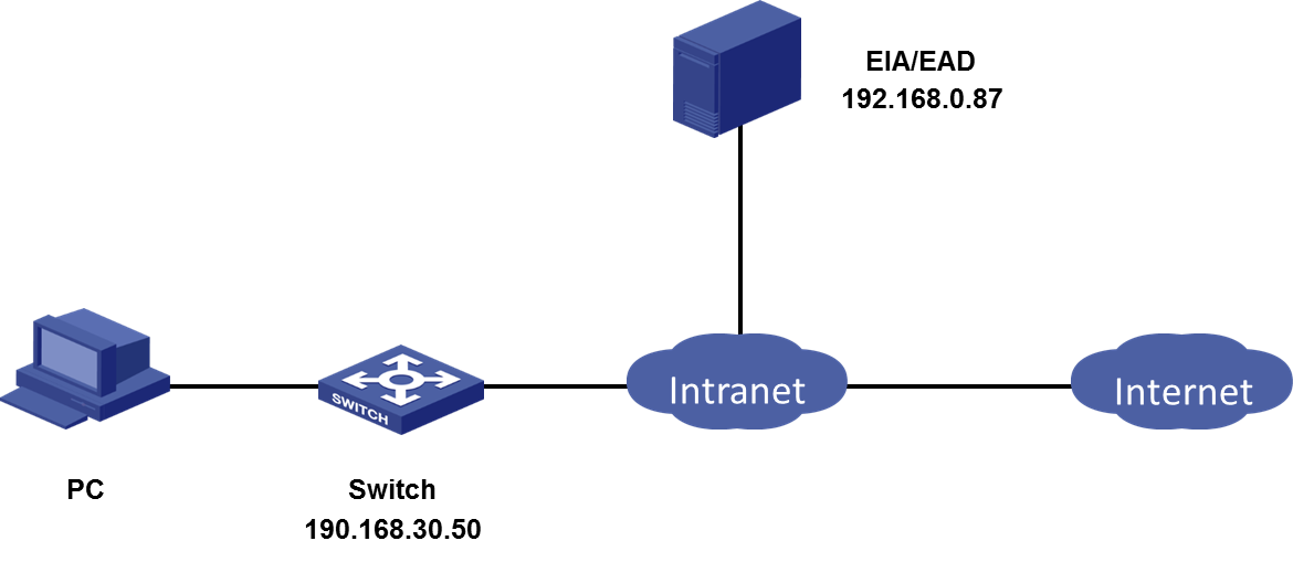
A company plans to perform security authentication based on user identity authentication, as shown in Figure 2.
|
|
NOTE: When EAD is deployed, it depends on the EIA component. Therefore, you must first deploy EIA before deploying EAD. |
· The IP address of the EIA&EAD server is 192.168.0.87.
|
|
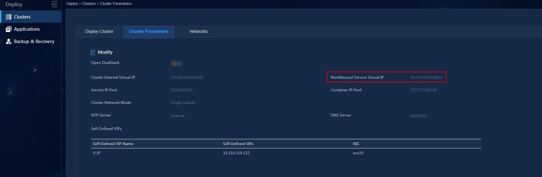
NOTE: · In a cluster deployment, specify the northbound service virtual IP as the IP address of the EIA/EAD server. Do not specify the node IP address of the EIA/EAD server. · The northbound service virtual IP (10.114.117.164) in the screenshot is for illustration only. It differs from the one used in this example. |
To identify the northbound service virtual IP of the EIA/EAD server in a cluster deployment:
a. Open the browser and enter https://ip_address:8443/matrix/ui in the address bar to open the Matrix page. The ip_address argument is either the northbound service virtual IP or the node IP.
b. On the top navigation bar, click DEPLOY. From the navigation pane, select Clusters. Click the Cluster Parameters tab.
c. Use the IP address in the Northbound Service Virtual IP field as the IP address of the server.
Figure 1 Viewing the IP address of the EIA/EAD server
· The IP address of the access device is 192.168.30.50.
· The PC has the Windows operating system and the iNode client installed.
Procedure
To provide the security policy service to access users, simply associate the required security policy with the access service requested by the user.
The configuration steps include configuring the EIA/EAD server and the access devices. Perform the following steps:
· Configuring the EAD server
¡ Configuring check items
¡ Configuring a security level
¡ Configuring a security policy
· Configuring the EIA server
¡ Configuring an access policy
¡ Adding an access service and applying the security policy
¡ Adding an access user and applying for the service for the access user
¡ Adding an access device
· Configuring the access device
Configuring check items
The optional security policy check items are as follows. In this step, select one or more of the following items as needed:
URL control
The domain/IP URL group management feature allows you to define domain/IP URL groups. Add a defined domain/IP URL group to the list in the URL control policy and permit or deny the access to the URLs that match the rules in that URL group.
To configure the URL control policy check items:
1. Add a URL group.
URL groups include IP URL groups and domain URL groups. According to actual requirements, you can add one or two types of URL groups. In this example, add an IP URL group as follows:
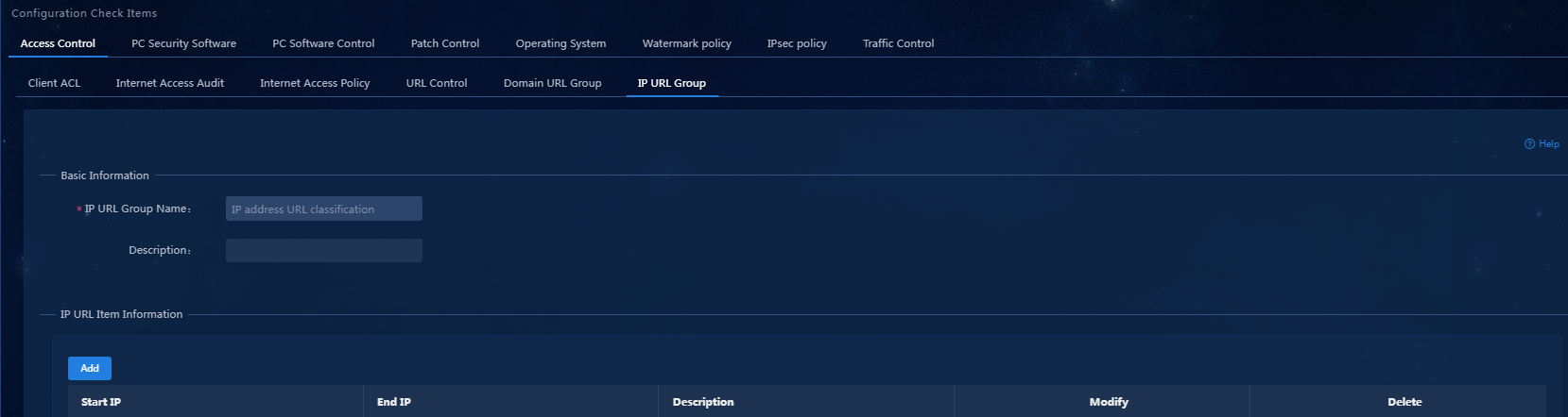
a. On the top navigation bar, click Automation. From the navigation pane, select Endpoint Business > Endpoint Security > Configuration Check Items. Click the Access Control > IP URL Group tab. (To add a domain URL group, click the Domain URL Group tab.)
b. Click Add. On the page that opens, enter the IP URL group name, as shown in Figure 3.
Figure 3 Adding an IP URL group
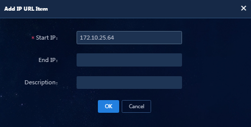
a. Click Add in the IP URL Item Information area. In the dialog box that opens, enter an IP address range, as shown in Figure 4.
Figure 4 Adding an IP URL item
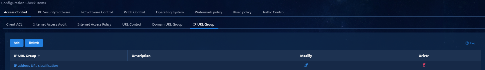
a. Click OK to finish adding the IP URL item. Click OK to complete the configuration, as shown in Figure 5.
Figure 5 The IP URL group configuration is completed
2. Add a URL control policy.
a. On the top navigation bar, click Automation. From the navigation pane, select Endpoint Business > Endpoint Security > Configuration Check Items. Click the Access Control > URL Control tab.
b. Click Add to access the Add URL Control Policy page, as shown in Figure 6.
Figure 6 Adding a URL control policy
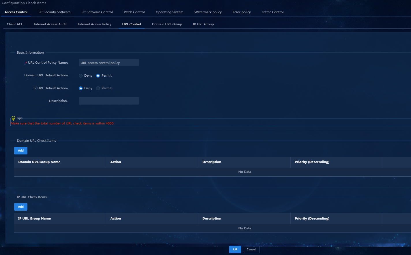
Parameters
- URL Control Policy Name: Enter the name of the URL control policy.
- IP URL Default Action: Select an IP URL default action. The Deny action means that the access will be denied when the URL that the end user accesses cannot match any rule in any group in the IP URL group list. The Permit action means that the access will be permitted.
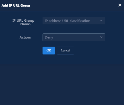
a. Click Add in the IP URL Check Items area, and enter the IP URL group name and action in the dialog box that opens. In this example, select Deny as shown in Figure 7.
Figure 7 Adding an IP URL group
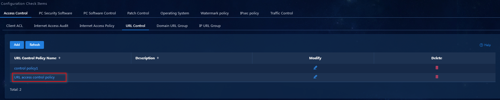
a. Click OK to finish adding the IP URL group. Click OK to complete the configuration, as shown in Figure 8.
Figure 8 The URL control policy configuration is completed
3. The check items of the URL control policy are configured. If you do not need to add more check items, proceed to "Adding a security policy."
PC software control group
A PC software control group defines the software products, processes, services, and files that need to be checked. Details of the check for the software products, processes, services, and files are as follows:
· Software—Check the software installation state.
· Process—Check the process running state.
· Service—Check the service start state.
· File—Check whether a file exists.
This document describes how to add a white software group named AccChecker as an example.
1. Calculate the MD5 digest.
a. On the top navigation bar, click Automation. From the navigation pane, select Endpoint Business > Endpoint Security > Configuration Check Items. Click the PC Software Control tab, as shown in Figure 9.
Figure 9 Downloading the MD5 tool
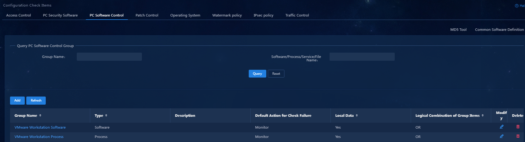
a. Click the MD5 Tool link at the top right corner of the page to download the MD5 tool to your local system. Double-click the downloaded file to open MD5 tool. The file MD5 digest calculator interface will open.
b. Click Please select an executable file and select the name of the process file you want to check. After selecting the file, click Calculate MD5 Digest to calculate the MD5 digest. After the calculation is completed, click the Copy button to save the MD5 digest.
2. Add a software control group.
a. On the top navigation bar, click Automation. From the navigation pane, select Endpoint Business > Endpoint Security > Configuration Check Items. Click the PC Software Control tab.
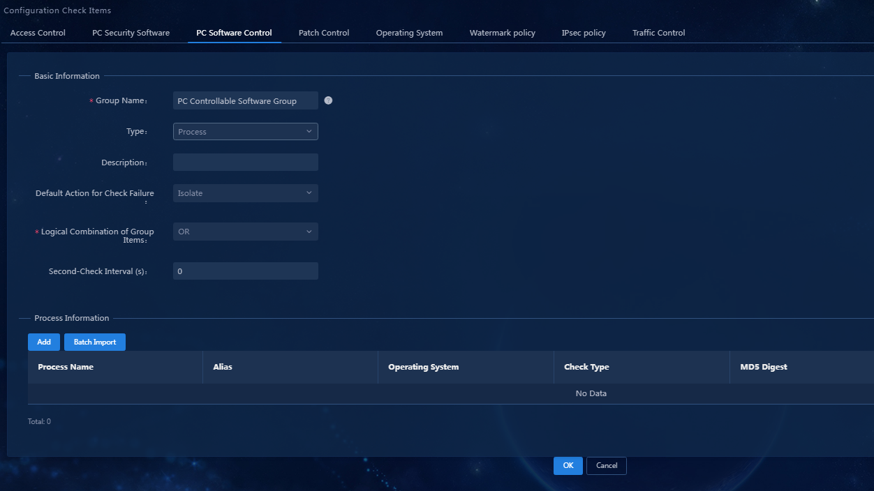
b. Click Add to access the Add PC Software Control Group page, as shown in Figure 10.
Figure 10 Adding a software control group
Parameters
- Group Name: Enter the name of the PC software control group.
- Type: Select the type for the PC software control group. Options include Software, Process, Service, and File. In this example, select Process.
- Default Action for Check Failure: Default action for check failure in the PC software control group in the security level. When you add a security level and do not use the global security mode for the PC software control group, the default action for check failure will be the security mode configured here. The global security mode can be configured on the Automation > Endpoint Business > Endpoint Security > Admission Security Levels page. When the global security mode is set, its priority is higher than the default action for check failure.
- Use the default settings for other parameters.
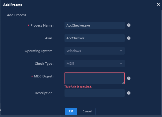
a. You can add a single process or bulk import processes. In this document, add a single process as an example. Click Add in the Process Information area to access the Add Process page, as shown in Figure 11.
Parameters
- Process Name: Enter the name of the process.
- Operating System: Select the operating system of the user endpoint. Select Windows as an example.
- Check Type: Select a check type. Select MD5 as an example.
- MD5 Digest: Paste the MD5 digest copied from the step "Calculate the MD5 digest." into this input box.
- Use the default settings for the other parameters.
a. Click OK to finish adding the PC software control group. Click OK to complete the configuration, as shown in Figure 12.
Figure 12 The PC software control configuration is completed
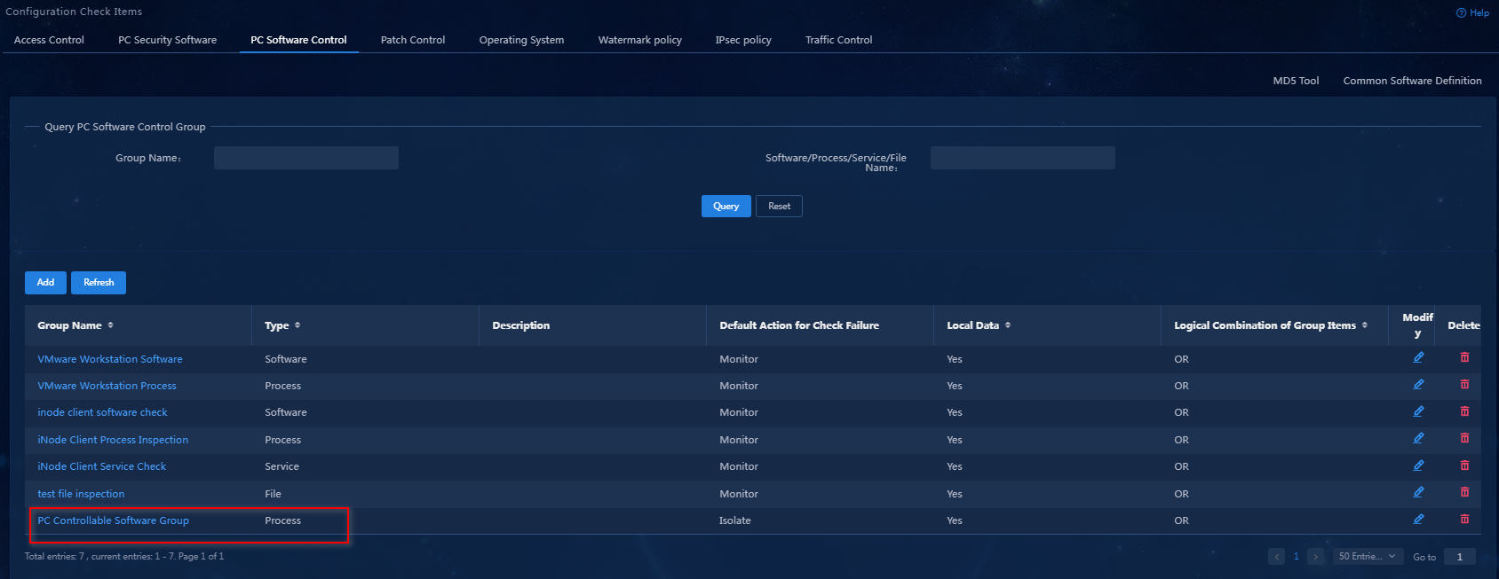
After the white software group named AccChecker is added, repeat the preceding steps to add the black software group named chrome. (Details not shown.)
|
|
NOTE: · MD5 check is an advanced process check method. You can calculate the MD5 digest of the software and distribute it to iNode clients through the EAD server. The clients then use the server-distributed MD5 digest to identify whether the end user is running the corresponding software. As a best practice, use the calculation tool provided by EAD to calculate the MD5 digests. · Rule for MD5 check on a certain process that must run: Match the process name corresponding to this process in the Windows task manager, and match the MD5 code corresponding to this process configured in the EAD server. If both matches succeed, the security check succeeds. If not, the security check fails. The white software group in this example belongs to this type. · Rule for MD5 check on a process prohibited from running: Match the process name corresponding to this process in the Windows task manager, and match the MD5 code corresponding to this process configured in the EAD server. When either of the matches succeeds, the security check fails. If not, the security check succeeds. The black software group in this example belongs to this type. · The complex process check and MD5 check methods are only applicable to the Windows operating system. They are not supported on Linux and Mac OS. |
3. The PC software control group is configured. If you do not need to add more check items, proceed to "Configuring a security level."
Anti-virus software check
To configure the anti-virus software policy check items:
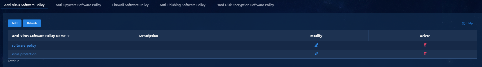
1. On the top navigation bar, click Automation. From the navigation pane, select Endpoint Business > Endpoint Security > Configuration Check Items. Click the PC Security Software > Anti-Virus Software Policy tab.
2. Click Add to access the Add Anti-Virus Software Policy page, as shown in Figure 13.
Figure 13 Adding an anti-virus software policy
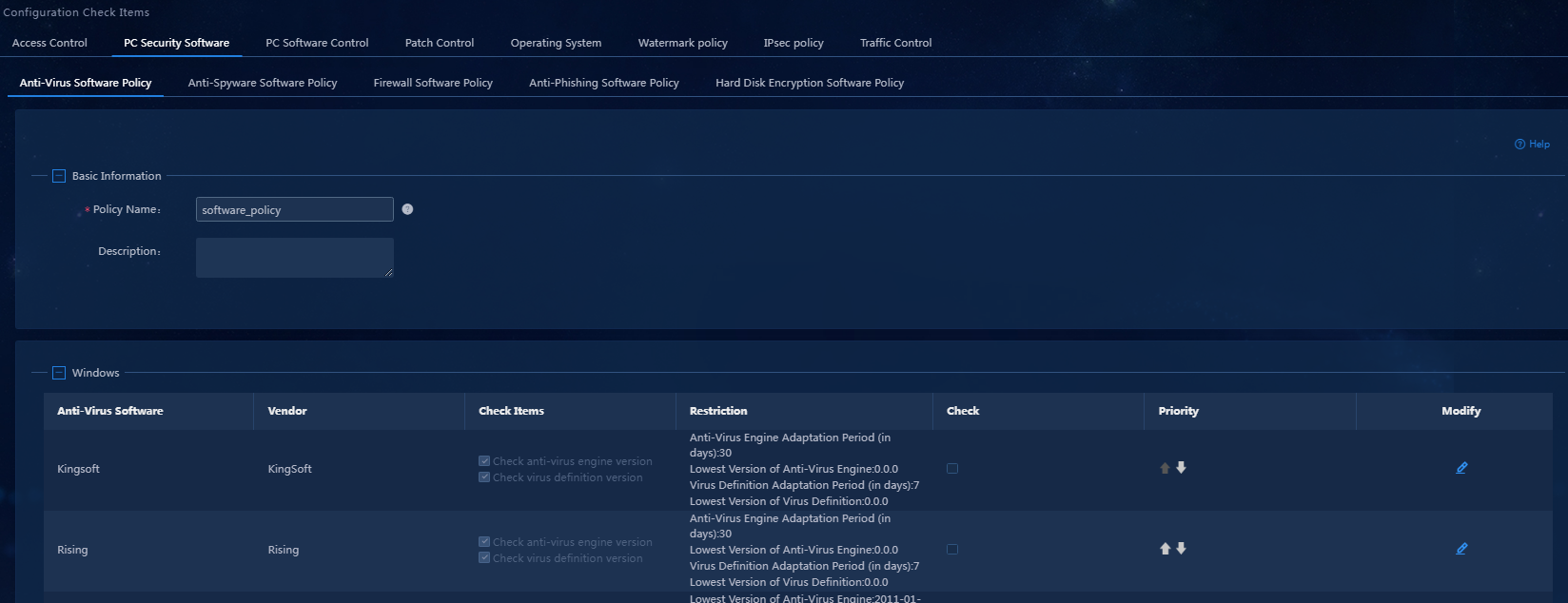
3. Enter the policy name. In the area below the Basic Information area, select the anti-virus software products as needed. In this example, select the Kingsoft anti-virus software for the Windows operating system. Select the check items in the Check Items column for the Kingsoft anti-virus software, as shown in Figure 14.
Figure 14 Selecting the anti-virus software
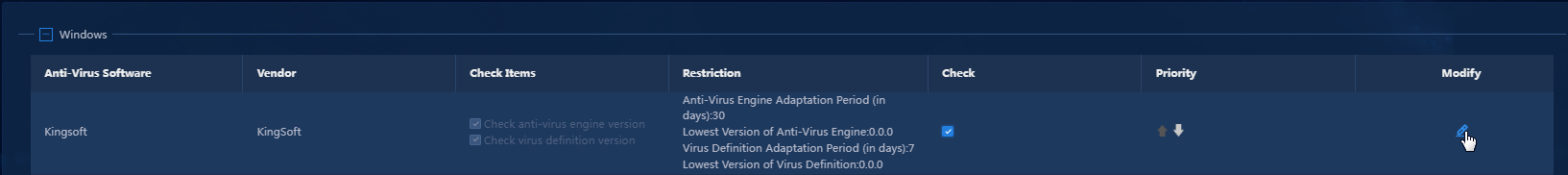
4. To check the version and other information
of the anti-virus software, click the Modify icon ![]() for
the anti-virus software. In the window that opens as shown in Figure 15,
configure the settings as needed. For the specific configuration method, see Table 1.
for
the anti-virus software. In the window that opens as shown in Figure 15,
configure the settings as needed. For the specific configuration method, see Table 1.
Figure 15 Configuring the Kingsoft anti-virus software
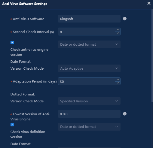
Table 1 Configuring the version of the anti-virus engine and the virus definition
|
Check method |
Version check mode |
Parameter settings |
|
Date format |
Specified version |
Select the minimum version of the anti-virus engine or virus definition in the format as YYYY-MM-DD. Any versions earlier than this date are considered unqualified. |
|
Auto adaptive |
Configure the adaptation period. You must have updated the anti-virus engine version or virus definition version within a certain number of days from the current time. |
|
|
Dotted format |
Specified version |
Enter the minimum version of the anti-virus engine or virus definition, typically in the format of X.X.X.X, which varies slightly by anti-virus software. Versions smaller than the string are considered unqualified. |
|
Date or dotted format |
Configure both the date format and the dotted format. When the virus definition version is checked: · If the date format of the virus definition version can be obtained, determine whether the date format is qualified. · If the date format cannot be obtained, determine whether the dotted format is qualified. |
|
5. Click OK to finish the anti-virus software settings. Click OK to complete the configuration, as shown in Figure 16.
Figure 16 The anti-virus software policy configuration is completed
6. The anti-virus software policy is configured. If you do not need to add more check items, proceed to "Configuring a security level."
Configuring a security level
A security level defines the processing methods when various check items do not meet the security policy requirements. Processing methods include Kick Out, Isolate, Monitor, and Inform. The following section describes how to configure the security level for the following check items:
· Software control group.
· Anti-virus software policy.
You do not need to separately configure security levels for other control policies. To configure a security level:
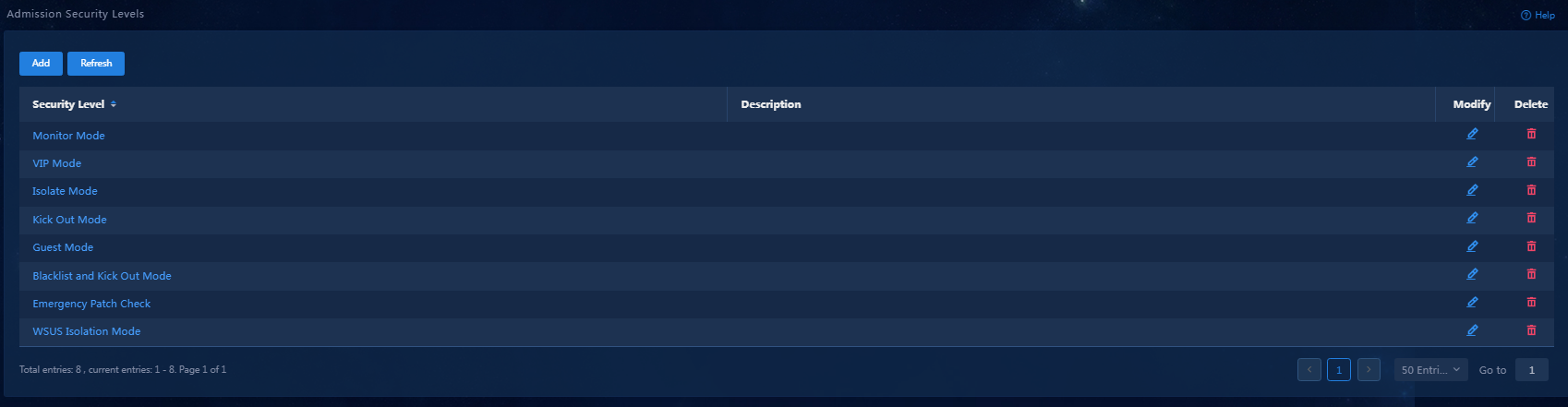
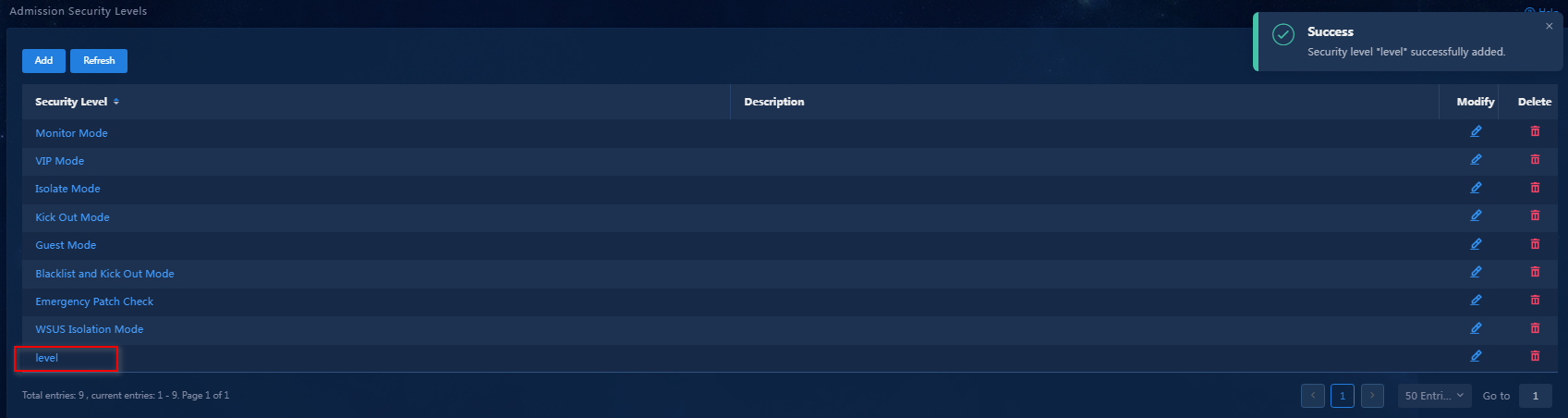
1. On the top navigation bar, click Automation. From the navigation pane, select Endpoint Business > Endpoint Security > Admission Security Levels.
The Admission Security Levels page opens, as shown in Figure 17.
Figure 17 Admission security levels
2. Click Add to access the Add Security Level page. Configure parameters in the Basic Information area, as shown in Figure 18.
Figure 18 Basic information for a security level
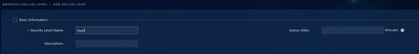
Parameters
¡ Security Level Name: Enter the name for the security level.
¡ Action After: This parameter can be set when the highest-level action in the security level is set to Isolate or Kick Out. When the value for this field is not 0 or empty, the system will prompt a user to resolve the security risks within the specified threshold time if the user fails to pass security authentication. If the user's security risks have not been resolved after the threshold time is reached, the system will isolate or kick out the user. Within the specified threshold time, the user can access the network normally. When the value for this field is 0 or empty, the user will be immediately isolated or kicked out if the user fails to pass security authentication.
¡ Use the default settings for other parameters.
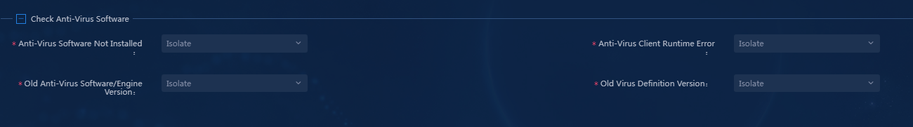
3. Configure the security level for the Check Anti-Virus Software area. In this example, select Isolate for all items in this area, as shown in Figure 19.
Figure 19 Security level of the anti-virus software
4. Configure the software control group security mode in the Check Applications area. Perform either of the following tasks:
¡ Select the Global Security Mode option and select the corresponding security mode from the list. All software control groups will use the same security mode.
¡ Click the Per-Group Configuration link to set different security modes for different software control groups.
In this example, select Kick Out and Isolate for the black software group (chrome.exe) and the white software group (AccChecker.exe), respectively, as shown in Figure 20.
Figure 20 Software control group security mode

5. Use the default settings for the other parameters. Click OK as shown in Figure 21.
Figure 21 The configuration of the admission security level is completed
Adding a security policy
A security policy is a collection of various check and monitoring policies. When adding a security policy, configure the required policies. To do that:
1. On the top navigation bar, click Automation. From the navigation pane, select Endpoint Business > Endpoint Security > Admission Security Policies. Click Add to access the Add Security Policy page.
2. Configure the parameters in the Basic Information area, as shown in Figure 22.
Figure 22 Basic information for a security policy
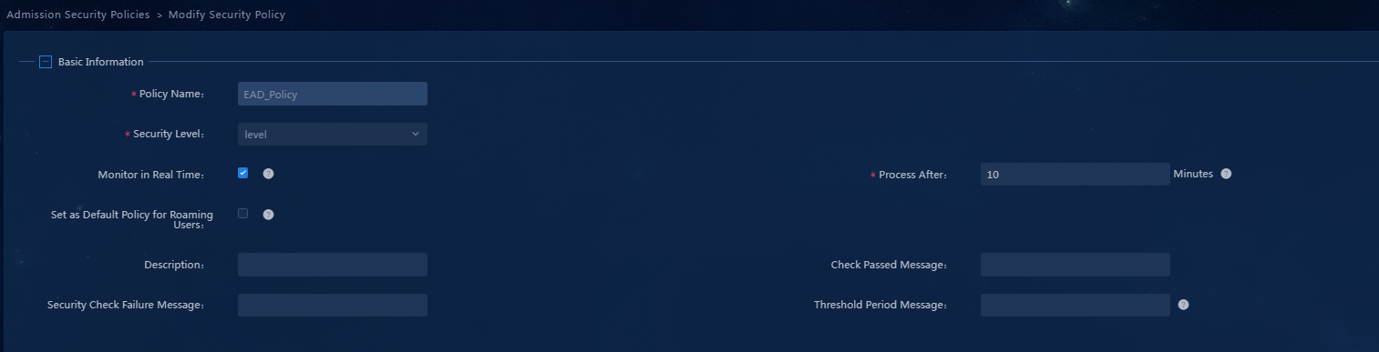
Parameters
¡ Policy Name: Enter the name of the security policy.
¡ Security Level: Select the security level configured in the previous step. If no separate security level has been configured, you can select a system-defined security level as needed.
¡ Monitor in Real Time: Select whether to perform real-time monitoring as needed. In this example, the following check items support real-time monitoring: PC software control group and anti-virus software.
¡ Process After: After selecting the Monitor in Real Time option, you must enter the waiting time before processing in this field. If you enter 0, the isolation or kicking out operation is immediately performed.
¡ Use the default settings for the other parameters.
3. If the application processing method includes the isolation mode, configure the isolation mode as shown in Figure 23.
Figure 23 Configuring the isolation mode
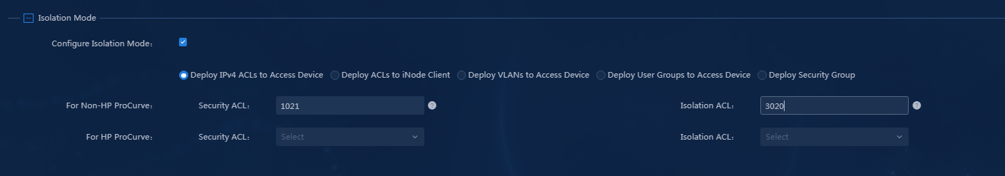
Parameters
¡ Configure Isolation Mode: Select this option.
¡ Select Isolation Mode: Select Deploy ACLs to Access Device, Deploy ACLs to iNode Client, or Deploy VLANs to Access Device. In this example, select Deploy ACLs to Access Device, set the security ACL to 3021, and set the isolation ACL to 3020. When ACLs are deployed, only the ACL numbers are deployed. The ACLs are configured on the access devices.
4. Configure the URL access control policy in the PC area, as shown in Figure 24.
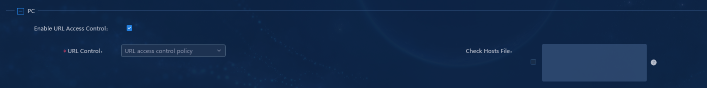
Parameters
¡ Enable URL Access Control: Select this option to enable URL access control.
¡ URL Control: Select a URL control policy as needed.
¡ Check Hosts File: Check the configuration items in the hosts file on the user endpoint. If the configuration items contain IP addresses not listed, the iNode client will kick out the corresponding users. Select this option as needed. To check the hosts file, enter the IPv4 addresses to be checked in the text box.
5. Configure the anti-virus software policy, as shown in Figure 25.
Figure 25 Anti-virus software check
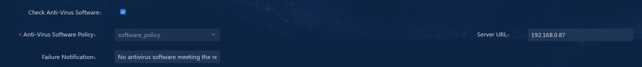
Parameters
¡ Check Anti-Virus Software: Select this option to enable the anti-virus software security check policy.
¡ Anti-Virus Software Policy: Select an anti-virus software policy as needed.
¡ Server URL: Enter the URL of the anti-virus software server. If a user does not meet anti-virus software requirements during the onboarding process, the iNode client will prompt the user to visit this server for repair when the Server URL option has been configured.
¡ Failure Notification: Enter the failure notification.
6. Configure the software control groups in the PC area. The specific configuration process is as follows, with the result shown in Figure 26.
a. Select the Check Applications option. Click the Per-Group Configuration link. The Application Control dialog box opens.
b. In the software control group list, click the Check Type column for a group to be added, and select Running Forbidden or Running Required from the list.
c. Then, select the option and click OK to complete the configuration.
Figure 26 Software control group
![]()
Parameters
¡ Check Applications: Select this option to enable the security policy for checking applications.
¡ Software Control Group List: Select the software control groups as needed and select the Running Forbidden or Running Required check type.
¡ Server URL: Enter the URL of the EAD server. If the software products used by a user during the onboarding process do not meet the requirements, the iNode client will prompt the user to visit this server for repair when the Server URL option has been configured.
¡ Failure Notification: Enter the failure notification.
7. Use the default settings for the other parameters and then click OK.
Configuring an access policy
1. On the top navigation bar, click Automation. From the left navigation pane, select User >Access Service. Click the Access Policy tab.
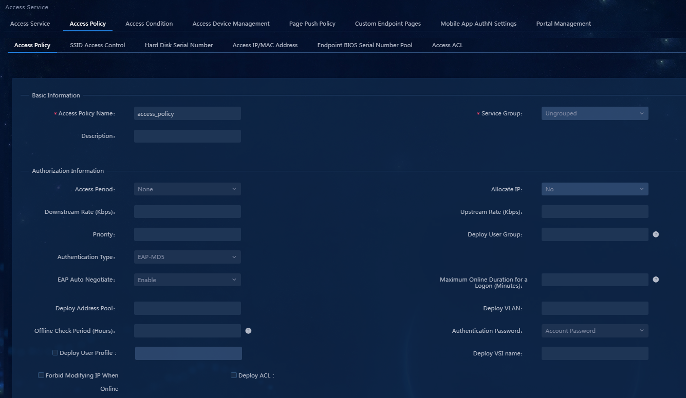
2. Click Add to access the Add Access Policy page. Because no access control is needed, enter only the access policy name, and use the default settings for the other parameters, as shown in Figure 27.
Figure 27 Add an access policy
|
|
NOTE: To deploy authorization information, make sure the attributes are supported on the device. For the authentication binding information to take effect, you must configure the corresponding information in the RADIUS attributes on the device. In this example, you do not need to deploy authorization information. The default settings apply. |
3. Click OK.
Adding an access service and applying the security policy
1. On the top navigation bar, click Automation. From the left navigation pane, select User > Access Service.
2. Click Add to access the Add Access Service page, as shown in Figure 28.
Figure 28 Adding an access service
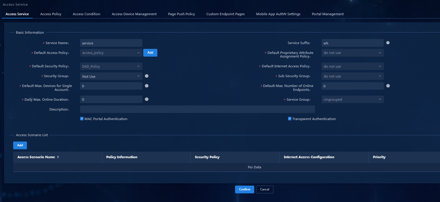
Parameters
¡ Service Name: Enter the service name.
¡ Service Suffix: Enter the service suffix. When the EIA server and the device collaborate to authenticate the access users, their configurations must comply with the constraints in Table 2. In this example, the first combination is used.
¡ Default Access Policy: Select the access policy configured in "Configuring an access policy."
¡ Default Security Policy: Select the security policy configured in "Adding a security policy," indicating that users using this access service will use this security policy.
¡ Use the default settings for other parameters.
Table 2 The constraint relationship between login name and account name
|
Login name |
Authentication domain on device |
Related command in device configuration |
Account name of the device management user in iMC |
|
X@Y |
Y |
With-domain |
X@Y |
|
Without-domain |
X |
||
|
X |
[Default Domain] (Default domain) |
With-domain |
X@[Default Domain] |
|
Without-domain |
X |
3. Click OK.
Adding an access user and applying for the service for the access user
1. On the top navigation bar, click Automation. From the navigation pane, select User > Access User.
2. Click Add.
Figure 29 Adding an access user
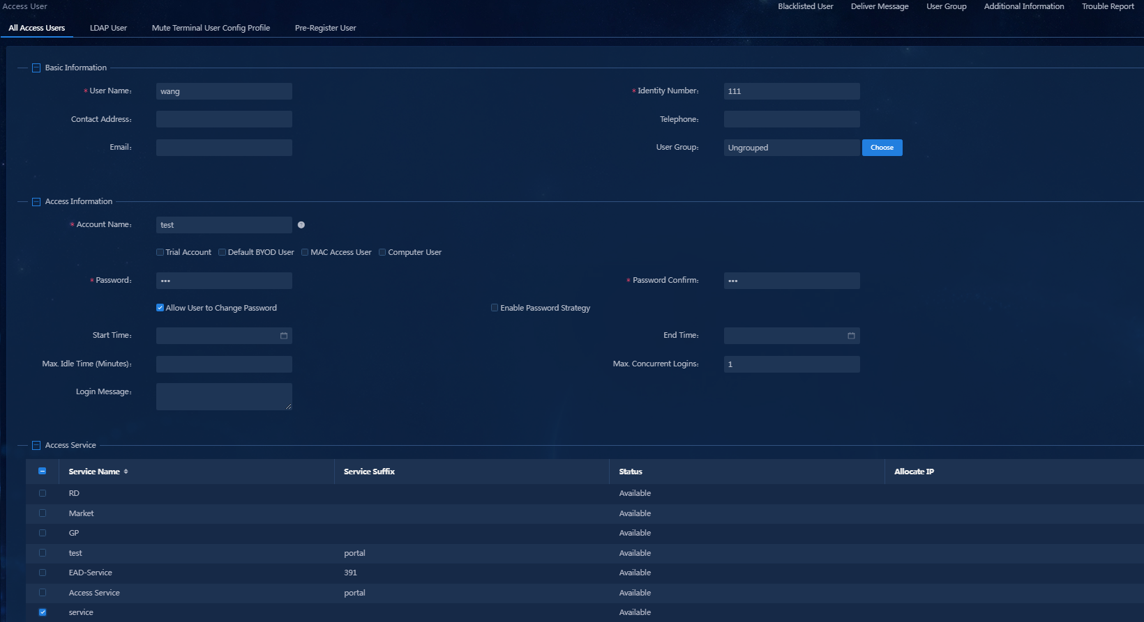
Parameters
¡ User Name: Enter the name of the access user.
¡ Account Name: Enter the account used for user authentication, which is unique in EIA.
¡ Password: Enter the password used for user authentication.
¡ Password Confirm: Re-enter the password used for user authentication.
¡ Access Service: Select the access service configured in "Adding an access service and applying the security policy" in the access service list.
¡ Use the default settings for other parameters.
3. Click OK.
Adding an access device
1. On the top navigation bar, click Automation. From the left navigation pane, select User > Access Service, and then click the Access Device Management > Access Device tab.
2. Click Add.
Figure 30 Adding an access device
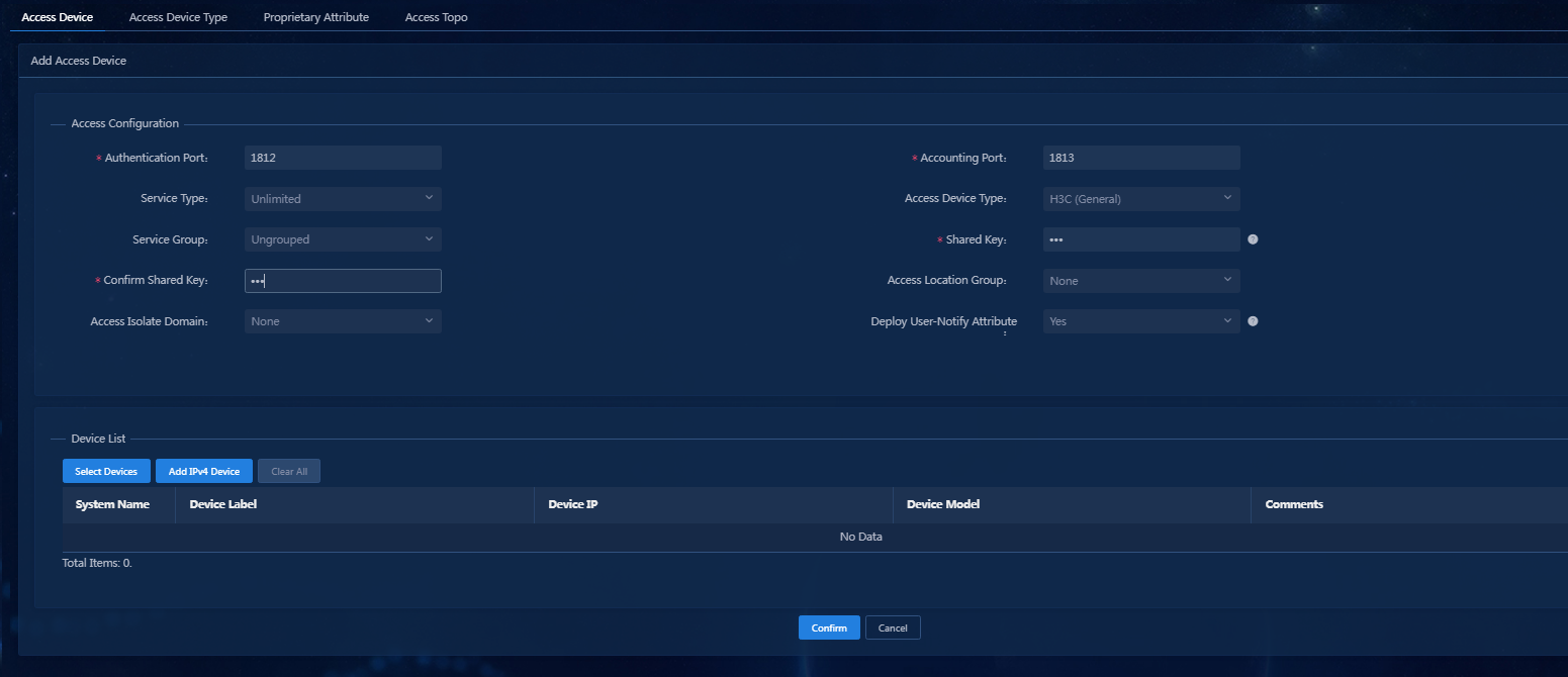
Parameters
¡ Authentication Port: Enter the authentication port number, which is 1812 by default.
¡ Accounting Port: Enter the accounting port, which is 1813 by default.
¡ Shared Key/Confirm Shared Key: Enter the same shared key twice. When the access device collaborates with EIA for authentication, this key is used to mutually authenticate each other. The configuration here must be consistent with the shared key configured at the CLI of the access device. If the keys are configured to be displayed in plain text on the Automation > User > Service Parameter > Access Parameters > System Settings > System Parameters page, you only need to enter the shared key once. In this example, the key is configured as 123.
¡ Use the default settings for the other parameters.
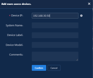
3. Click the Add IPv4 Device button in the Device List area, and enter the start IP address (access device IP address) in the dialog box that opens, and then click OK as shown in Figure 31.
Figure 31 Adding an access device
4. Click OK.
Figure 32 Adding the IPv4 device completed
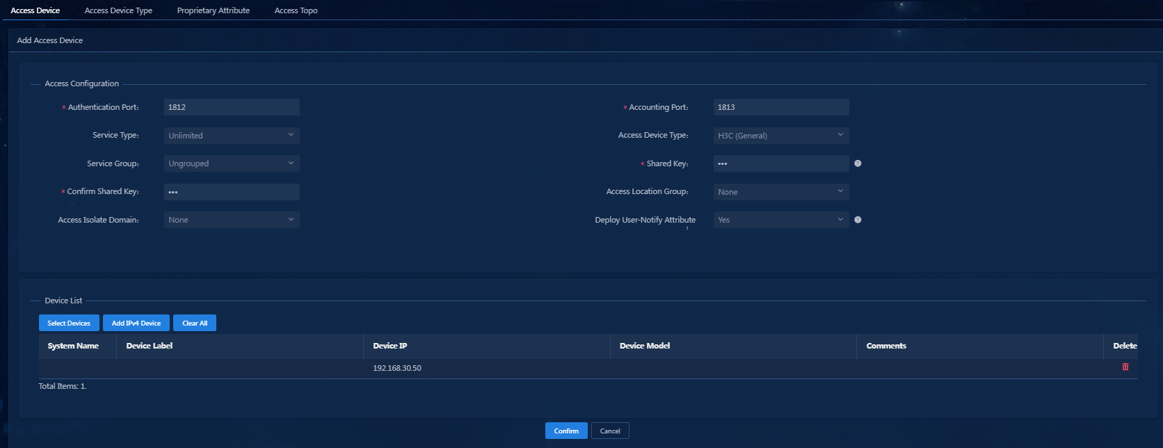
5. Click OK to add the access device.
Configuring the access device
Configure a server to perform identity authentication and security authentication when users log in, and configure a simple ACL control policy. Here, configure the EIA/EAD server as the AAA server and security check server.
Then, Telnet to the access device by using the CLI window of the Windows operating system as follows:
1. Telnet to the access device and enter system view.
2. Configure the RADIUS scheme. Specify the IP address of the EIA/EAD server. The listening port and shared key need to match the settings in "Adding an access device."
[Device]radius scheme 390
New Radius scheme
[Device-radius-390]primary authentication 192.168.0.87 1812
[Device-radius-390]primary accounting 192.168.0.87 1813
[Device-radius-390]key authentication 123
[Device-radius-390]key accounting 123
[Device-radius-390]nas-ip 192.168.30.50
[Device-radius-390]user-name-format with-domain
[Device-radius-390]quit
3. Create a domain and configure users to use the RADIUS scheme for authentication, authorization, and accounting when accessing the device. When the EIA/EAD server and the device collaborate to authenticate access users, their configuration must comply with the constraints specified in Table 2.
[Device]domain wh
New Domain added
[Device-isp-wh]authentication lan-access radius-scheme 390
[Device-isp-wh]authorization lan-access radius-scheme 390
[Device-isp-wh]accounting lan-access radius-scheme 390
[Device-isp-wh]quit
4. Configure 802.1X. Enable 802.1X authentication globally and on the interface to enable the authentication feature for the interface.
[Device]dot1x
802.1x is enabled globally
[Device]dot1x interface Ethernet 1/0/3
802.1x is enabled on port Ethernet1/0/3
5. Create ACLs based on the isolation mode configured in the security policy. Insecure ACL 3020 only allows users to access limited resources, while secure ACL 3021 does not impose any restrictions.
[Device]acl number 3020
[Device-acl-adv-3020]rule 1 permit ip destination 192.168.0.87 0
[Device-acl-adv-3020]rule 2 deny ip
[Device-acl-adv-3020]quit
[Device]acl number 3021
[Device-acl-adv-3021]rule 1 permit ip
[Device-acl-adv-3021]quit
Using the iNode client for verifying the security policy
The following section describes the results of verifying security policy check failures involved in the example.
Installing the iNode PC client with the 802.1X function
The current EIA is compatible with all versions of iNode, and you can select the version of iNode as needed.
Verifying the configuration
Using the iNode client to perform identity authentication and security authentication for the client
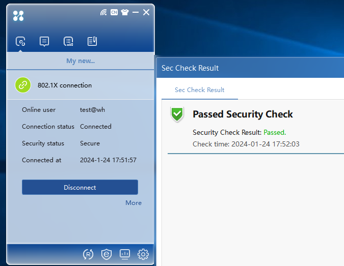
Enter your account and password on the 802.1X authentication interface, and then click the Connect button for authentication. After you pass identity authentication and security authentication, the status of identity authentication and security authentication will be displayed on the interface, as shown in Figure 33.
Figure 33 802.1X authentication
Verifying the URL control policy
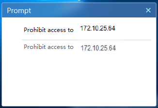
1. Enter a disallowed URL in the IE browser. This URL includes an IP URL group that is prohibited by the URL control policy.
2. When the URL fails to be accessed, the iNode client displays a window as shown in Figure 34.
Figure 34 Prompt information for access denied
Verifying white software check failure
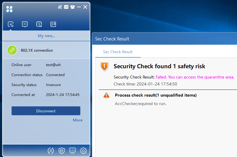
1. Perform 802.1X authentication when software products in the white software group are not running. After identity authentication succeeds, security authentication begins. The security authentication result is prompted in the information area.
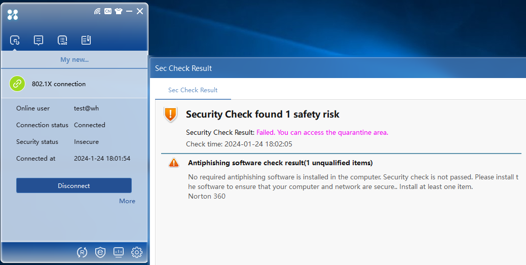
2. The white software group check has failed. The server will isolate the user according to the previously configured isolation mode. The icon of the 802.1X client displays the isolated state. The page displaying the detailed security check results will automatically open, as shown in Figure 35.
Figure 35 Security check result
Verifying black software check failure
1. Perform 802.1X authentication when the software products in the black software group are running.
2. After identity authentication succeeds, security authentication begins. The authentication information area displays the result of security authentication, as shown in Figure 36.
Figure 36 Black software group check failure
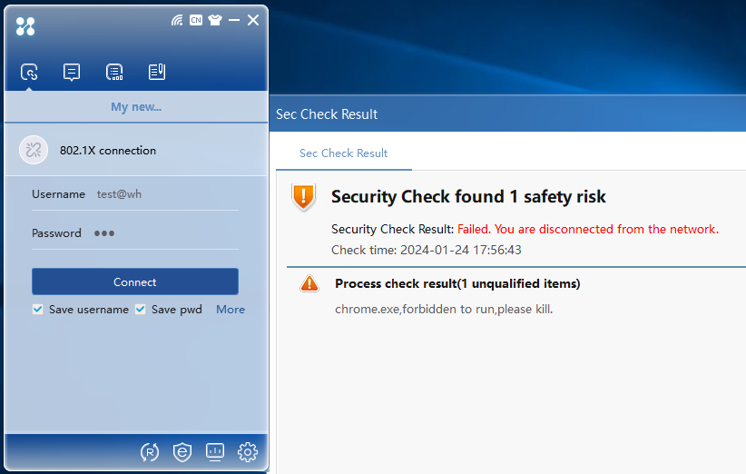
3. The black software group check fails, and the EAD server will kick out the user according to the previously configured Kick Out mode. The 802.1X client icon displays the offline state.
Verifying the anti-virus software check failure
1. The required anti-virus software products are not installed. After identity authentication succeeds, security authentication begins. The authentication information area displays the failure result of security authentication, as shown in Figure 37.
Figure 37 Anti-virus software check failure
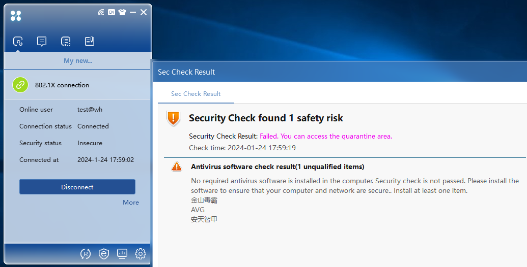
2. If the anti-virus software check fails, the server will isolate the user based on the previously configured isolation mode.
ACL access restrictions
The isolation ACL 3020 only allows the user to access limited resources, while the security ACL 3021 imposes no restrictions, as shown in the following diagram.
Figure 38 Security ACL 3021
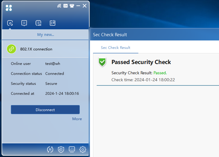
Figure 39 Isolation ACL 3020