- Released At: 14-03-2024
- Page Views:
- Downloads:
- Table of Contents
- Related Documents
-
H3C EAD URL Access Control
Configuration Examples
Document version: 5W100-20240314
Software version: EAD (E6204)
Copyright © 2024 New H3C Technologies Co., Ltd. All rights reserved.
No part of this manual may be reproduced or transmitted in any form or by any means without prior written consent of New H3C Technologies Co., Ltd.
Except for the trademarks of New H3C Technologies Co., Ltd., any trademarks that may be mentioned in this document are the property of their respective owners.
The information in this document is subject to change without notice.
Contents
Configuring the URL control policy
Adding an admission security policy
Introduction
EAD URL access control management allows for centralized management of access control policies. The network administrator configures URL control policies, specifying domain URL groups and IP URL groups to be controlled. Then, the security policies are configured to apply these URL control policies. Upon iNode authentication, the URL control policies can be deployed to iNode clients via security policies. Based on the policies, iNode clients allow or prohibit endpoint users from accessing URLs.
Usage guide
Application scenarios
This feature is applicable to the scenarios such as enterprises, schools, or any other setting that requires control over endpoint user access to URLs.
Configuration example
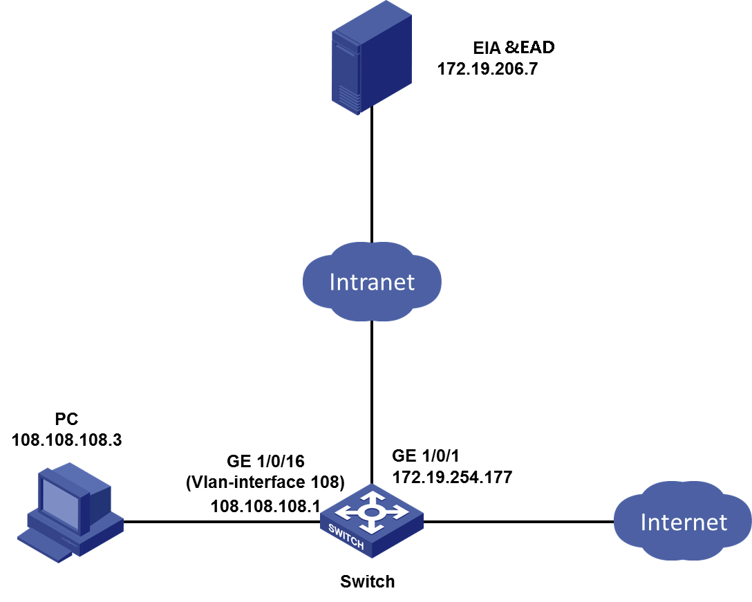
Network configuration
A company plans to initiate URL access control. After a user accesses the network, the URLs they visit are monitored, as shown in Figure 2.
|
|
IMPORTANT: EAD deployment depends on the EIA component. To deploy EAD, deploy EIA first. |
· As shown in Figure 2, configure the IP address of the EIA or EAD server as 172.19.206.7.
|
|
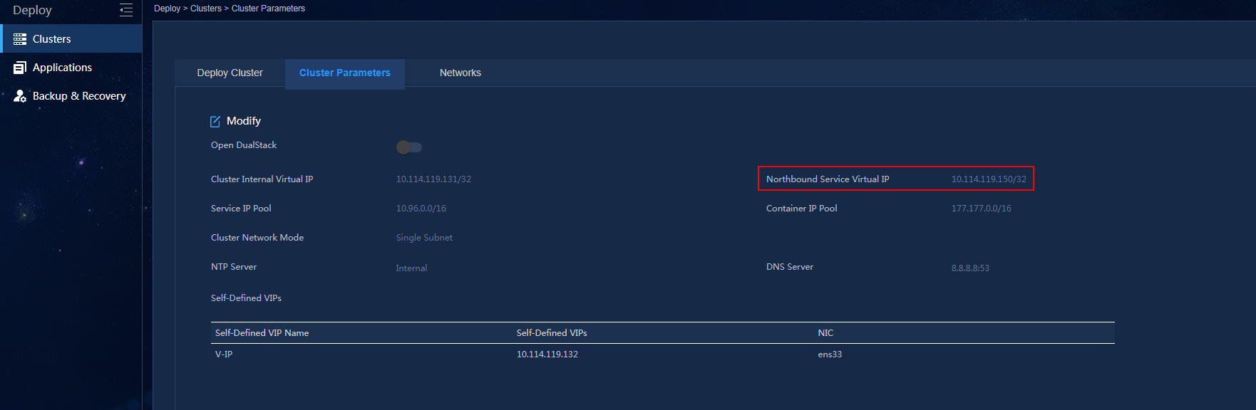
NOTE: · In a cluster deployment, specify the northbound service virtual IP as the IP address of the EIA or EAD server. Do not specify the node IP address of the EIA or EAD server. · The northbound service virtual IP (10.114.117.164) in the screenshot is for illustration only. It differs from the one used in this example. |
To obtain the northbound service virtual IP of the EIA or EAD server:
a. Enter https://ip_address:8443/matrix/ui in the address bar of the browser to open the Matrix page. ip_address represents the northbound service virtual IP or node IP address.
b. On the top navigation bar, click Deploy. From the navigation pane, select Clusters. Click the Cluster Parameters tab.
c. The displayed northbound service virtual IP is the IP address of the EIA or EAD server.
Figure 1 Obtaining the IP address of the EIA or EAD server
· The IP address of VLAN interface Vlan-interface 108 where GigabitEthernet1/0/16 on the user side of the access device resides is 108.108.108.1.
· The IP address of the PC is 108.108.108.3. The PC must be installed with the Windows operating system and prepare for the iNode client.
The software versions used in this example are as follows:
· EIA and EAD: EIA (E6204) and EAD (E6204).
· Access device: H3C S5820V2-54QS-GE.
· iNode: iNode PC 7.3 (E0585)
Procedures
· Configure the URL control policy.
¡ Domain URL group
¡ IP URL group
¡ URL control policy
· Configure the terminal security policy.
· Configure the EIA server.
¡ Add access device
¡ Adding an access policy
¡ Adding an access service
¡ Adding an access user
· Set up the Portal server
Configuring the URL control policy
Domain URL group and IP URL group can be referenced in a URL control policy. The URL control policy can be issued to iNode clients through the security policy. Based on the policy, iNode clients allow OR prohibit end user's behavior of accessing the URL.
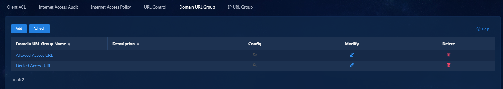
Adding a domain URL group
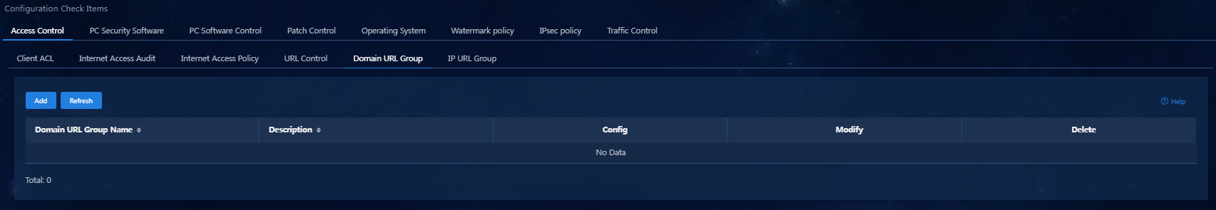
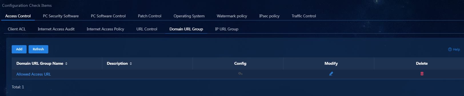
1. On the top navigation bar, click Automation. From the navigation pane, select Endpoint Business > Endpoint Security > Configuration Check Items > Access Control > Domain URL Group.
Figure 3 Domain URL Group page
2. Click Add.
Figure 4 Configuring a domain URL group.
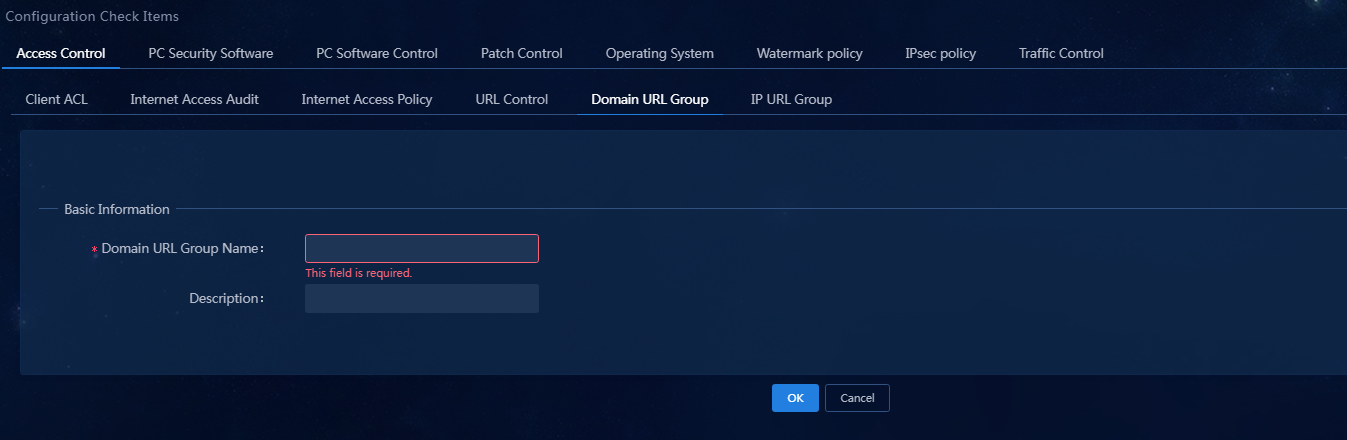
3. Enter the domain URL group name and click OK. You can view the domain URL group in the domain URL group list, as shown in Figure 5.
Figure 5 Domain URL group page
4. Click the icon in the Config column for a domain URL group to enter the URL item adding page, as shown in Figure 6.
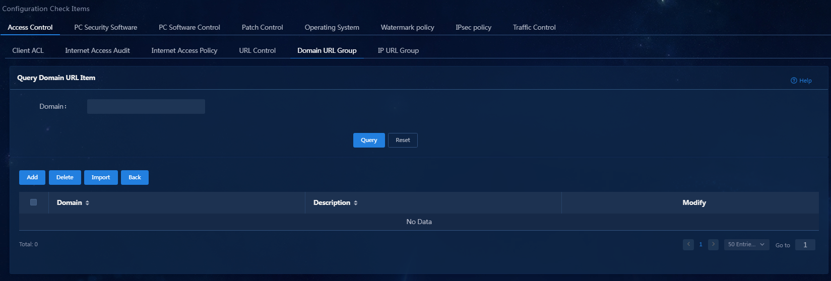
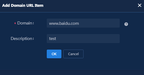
5. Click Add. In the dialog box that opens, enter a domain name that can be accessed. This example enters www.baidu.com.
Figure 7 Adding a domain URL item
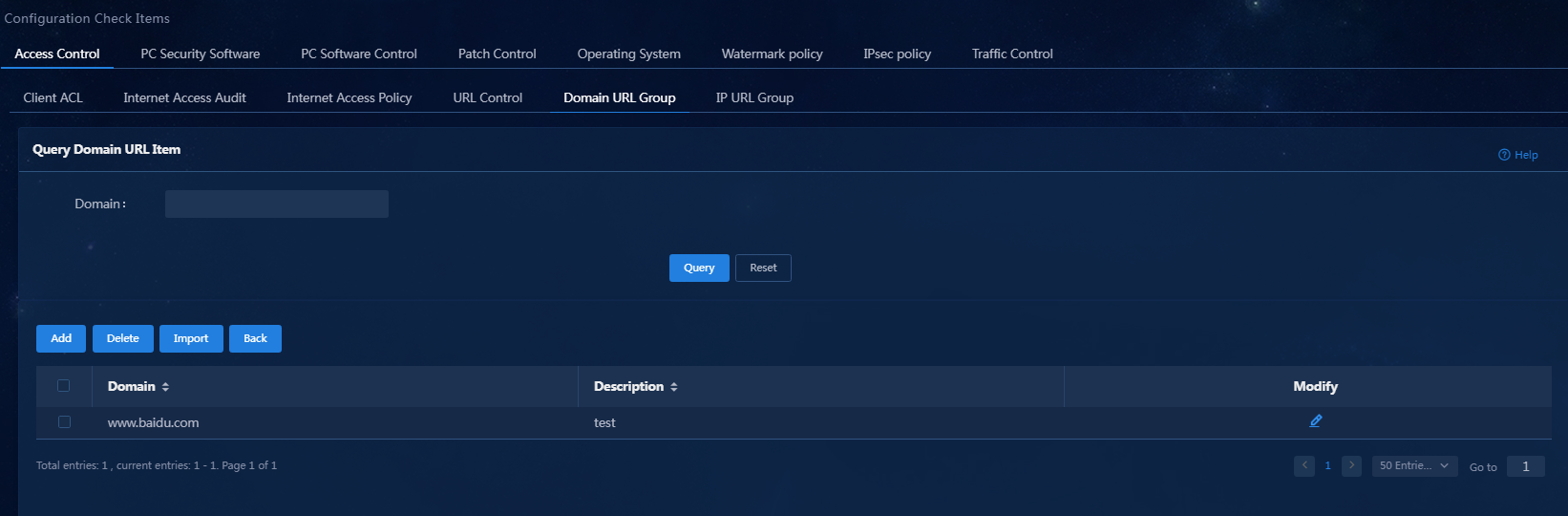
6. Click OK. Then, you can view the newly added domain
name on the Query Domain URL Item page, as shown in Figure 8.
7. Click Back to return to the Domain URL Group page.
8. Add a URL that will be denied in the same manner. This example adds www.h3c.com as Denied Access URL.
Figure 9 Domain URL Group page
Adding an IP URL group
1. On the top navigation bar, click Automation. From the navigation pane, select Endpoint Business > Endpoint Security > Configuration Check Items > Access Control > IP URL Group.
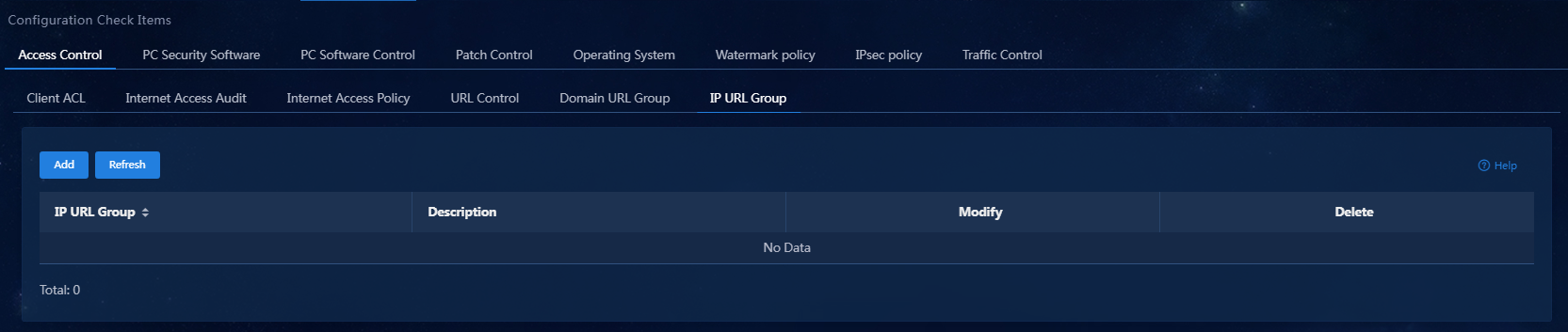
2. Click Add.
Figure 11 Configuring an IP URL group
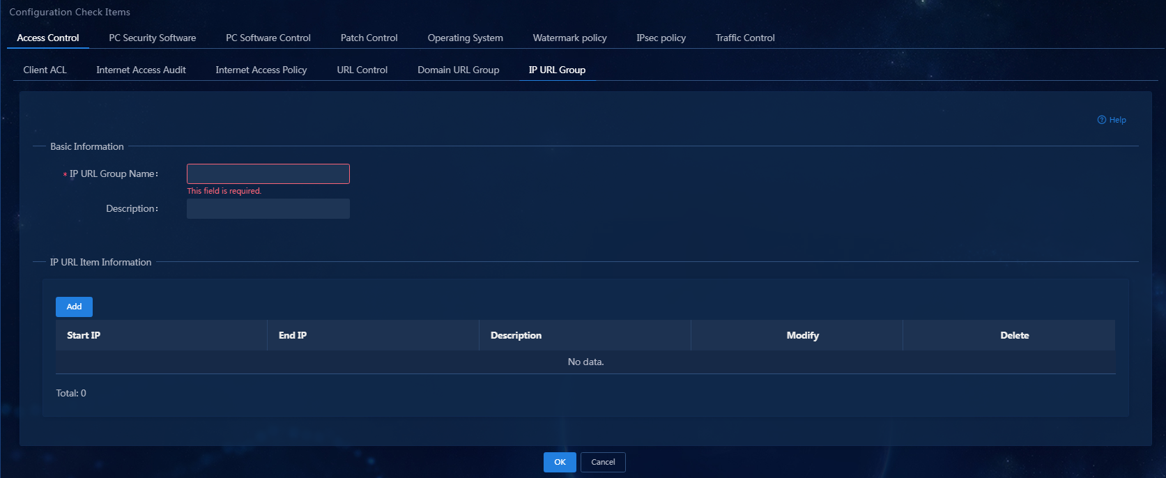
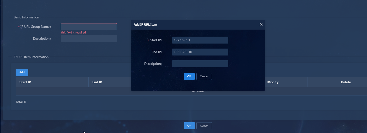
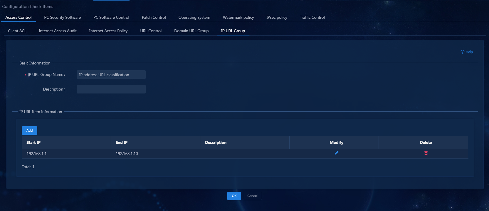
3. Enter the IP URL group name, and then click Add. In the dialog box that opens, add an IP URL item with start IP 192.168.1.1 and end IP 192.168.1.10, as shown in Figure 12.
Figure 12 Adding an IP URL item
4. Click OK.
Figure 13 IP URL item completed
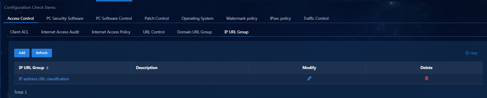
5. Click OK to complete the addition of the IP URL group. You can view the newly added IP URL group in the IP URL group list, as shown in Figure 14.
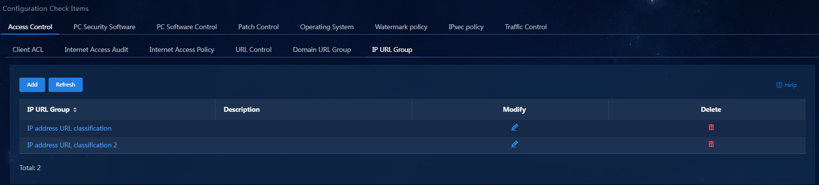
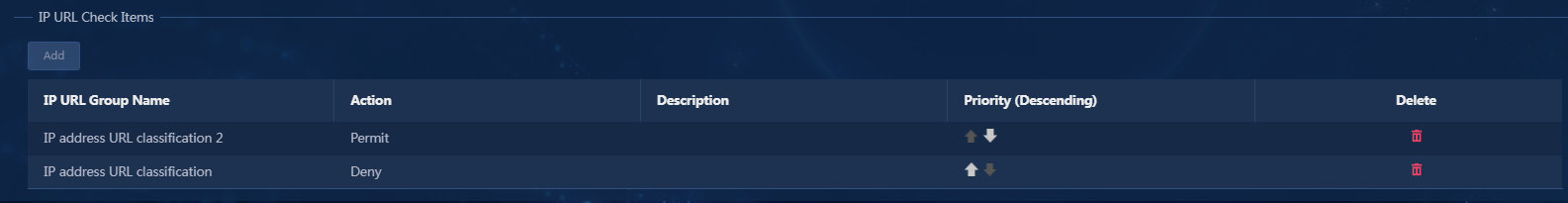
6. Follow the same method to add an IP URL group named IP address URL classification 2, as shown in Figure 15.
Adding a URL control policy.
|
|
NOTE: After you configure the permit and deny actions for domain URL items (the default action is permit), the URL will first attempt to match domain URL items according to the priority. If a match is found, the system will take the corresponding action. If no match is found, the system will take the default action, which is permit in this example. The guidelines for IP URL groups are similar to those of domain URL groups. |
1. On the top navigation bar, click Automation. From the navigation pane, select Endpoint Business > Endpoint Security > Configuration Check Items > Access Control > URL Control.
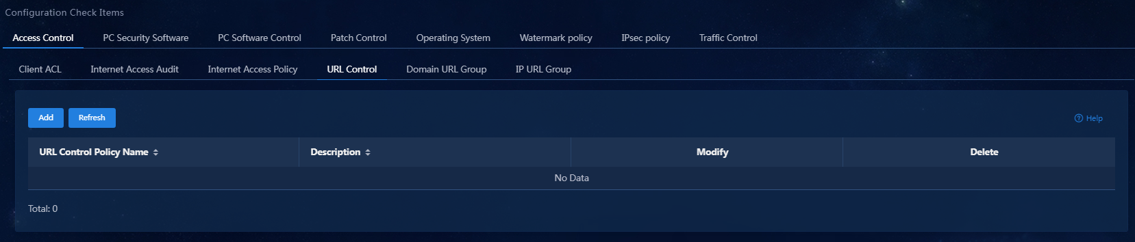
2. Click Add.
Figure 17 Adding an URL control policy
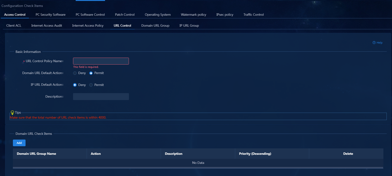
3. Enter the URL control policy name, set Domain URL Default Action to Permit and IP URL Default Action to Deny, as shown in Figure 18.
Figure 18 Configuring an URL control policy
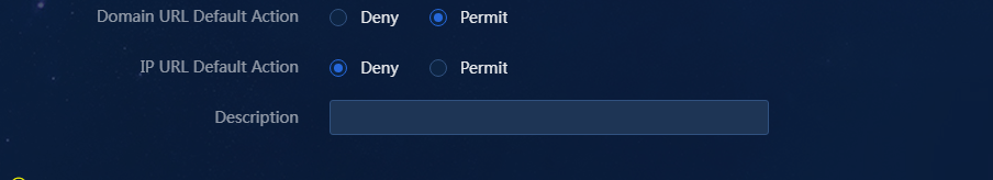
4. In the Domain URL Check Items area, click Add.
Figure 19 Adding a domain URL group

5. Select a domain URL group and the action. Click OK. You can view the newly added domain URL group in the Domain URL Check Items area. Use the same method to add an URL that will be denied.
Figure 20 Viewing domain URL groups
6. In the IP URL Check Items area, click Add.
Figure 21 Adding an IP URL group
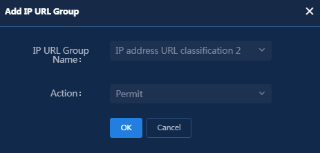
7. Select an IP URL group and the action. Click OK. You can view the newly added domain URL group in the Domain URL Check Items area. Use the same method to add an URL that will be permitted.
Figure 22 Figure 20 Viewing IP URL groups
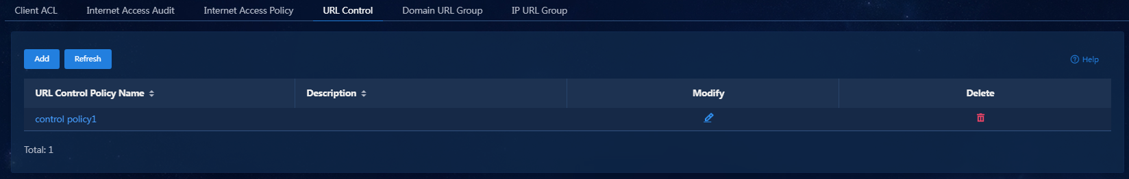
8. Click OK to complete the addition of the URL control policy. You can view the new URL access control policy on the URL control policy list.
Figure 23 URL control policy added successfully
Adding an admission security policy
1. Select the "Automation" tab, click on "Terminal Business > Terminal Security Management > Admission Security Policy" in the navigation tree, to access the Admission Security Policy page, as shown in <field name="Ref" value="Figure 24"/>.
2. On the top navigation bar, click Automation. From the navigation pane, select Endpoint Business > Endpoint Security > Admission Security Policies.
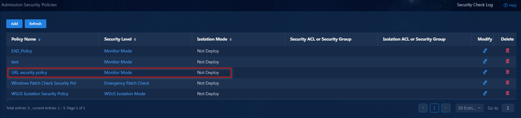
Figure 24 Admission Security Policies page

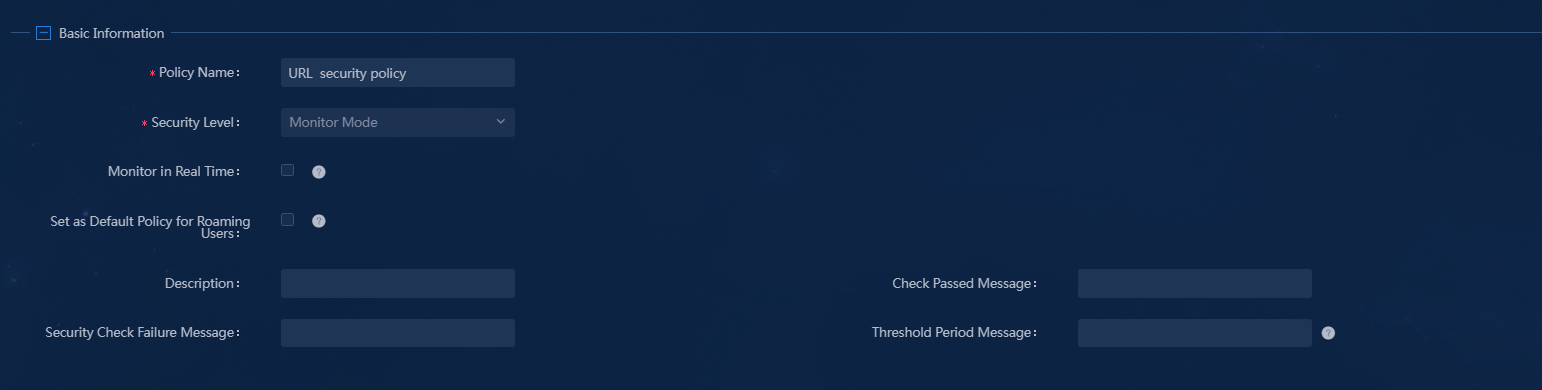
3. Click Add. On the page that opens, enter the security policy name and select Monitor Mode for the Security Level field.
Figure 25 Adding a security policy
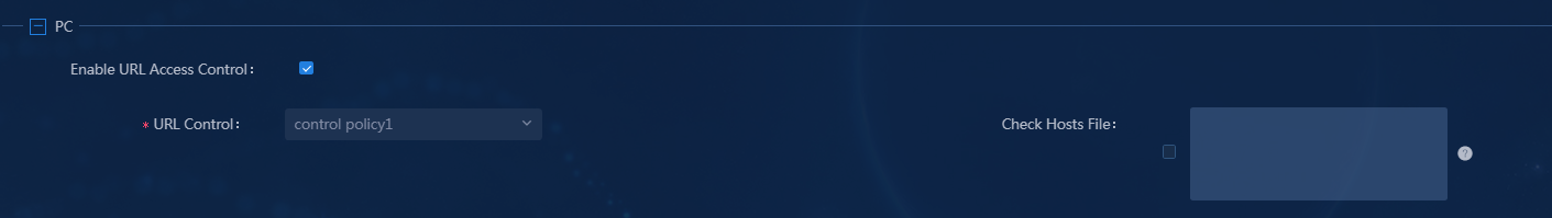
4. Select Enable URL Access Control, select a URL control policy, and select and fill in the Check Hosts File field.
Figure 26 Configuring a URL control policy
Parameters:
¡ Check Hosts File: (Optional.) Checking the hosts file configuration items on a user endpoint. If the configuration items contain IP addresses that are not on the list, the iNode client forces the user to go offline.
For more information about parameters, see the online help for the product.
5. Click OK. You can view the newly added admission security policy on the Admission Security Policies page.
Figure 27 Admission security policy added successfully
Setting up the EIA server
Adding an access device
You must add an access device to the EIA server before the EIA server can work with the access device for authentication.
To add an access device to the EIA server:
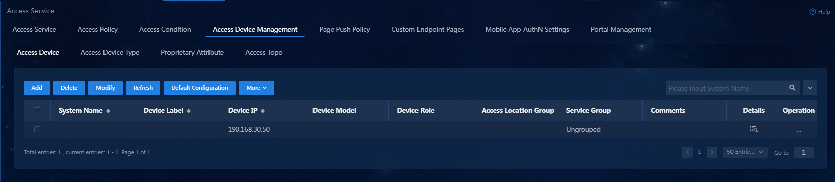
1. On the top navigation bar, click Automation. From the navigation pane, select User > Access Service. Click the Access Device Management tab.
Figure 28 Access device configuration page
2. Click Add.
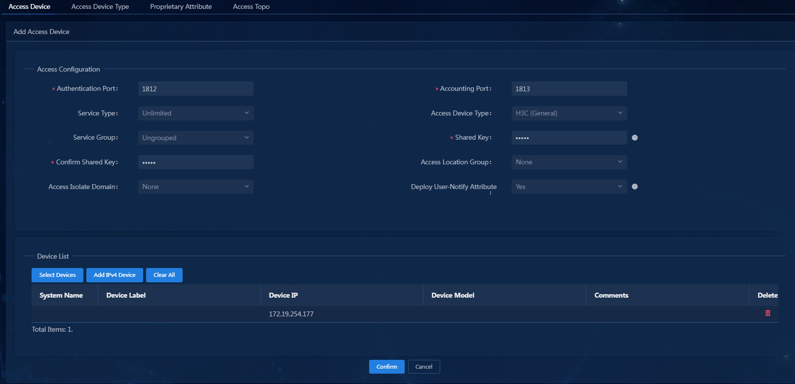
Figure 29 Adding an access device
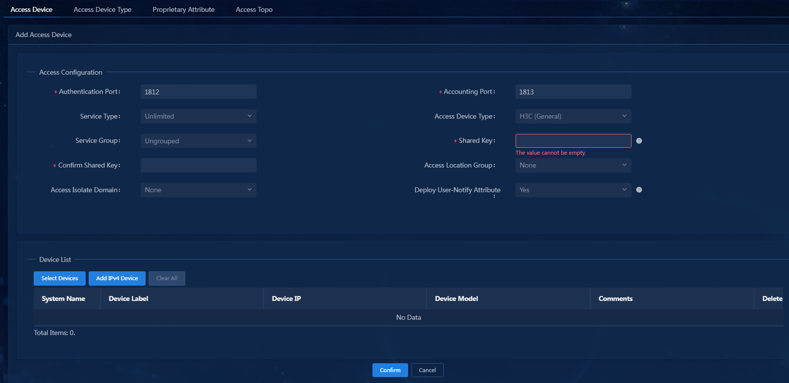
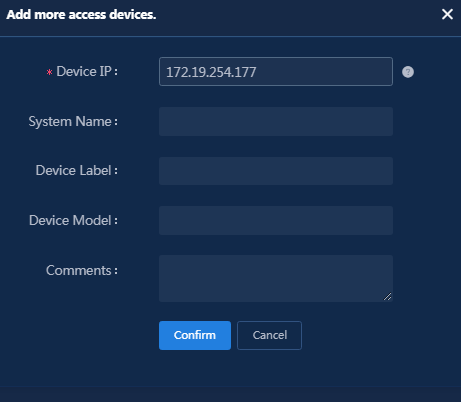
3. Click Add IPv4 Device in the Device List area. In the window that opens, enter the IP address and name of the access device in the Device IP field, and then click Confirm.
Follow these restrictions and guidelines when adding the access device:
¡ If the RADIUS scheme contains a NAS IP specified by using the nas ip command for the access device, specify that IP address on the EIA server.
¡ If the RADIUS scheme does not contain a NAS IP, specify the IP address of the Layer 3 Ethernet interface or VLAN interface that connects the access device to the EIA server.
Figure 30 Manually adding an access device
4. Configure the following common parameters:
¡ Authentication Port: Specify the RADIUS authentication service port on the EIA server. It must be the same as that specified on the access device. Typically, use the default service port 1812.
¡ Accounting Port: Specify the RADIUS accounting service port on the EIA server. It must be the same as that specified on the access device. Typically, use the default service port 1813.
|
|
IMPORTANT: You must use the EIA server to provide both authentication and accounting services. You cannot use the EIA server as the authentication server and another server as the accounting server. |
¡ Shared Key/Confirm Shared Key: Enter a shared key in the Shared Key field. If the system is configured to display keys in ciphertext, you must enter the key again in the Confirm Shared Key field for confirmation. In this example, enter movie.
The shared key is used for secure communication between the server and the access device.
The shared key specified on the EIA server must be the same as that specified on the access device.
You can enter the shared key once if you selected Plaintext in the System Settings page.
¡ Use the default settings for the other parameters.
Figure 31 Configure common parameters
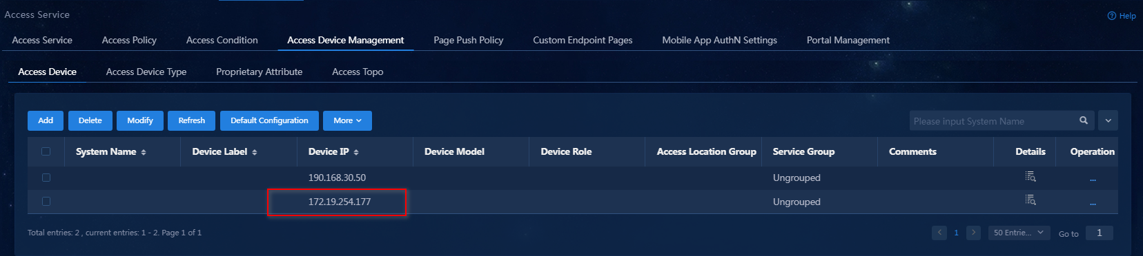
5. Click OK. Verify that the access device has been added to the access device list.
Figure 32 Verifying that the access device has been added to the access device list
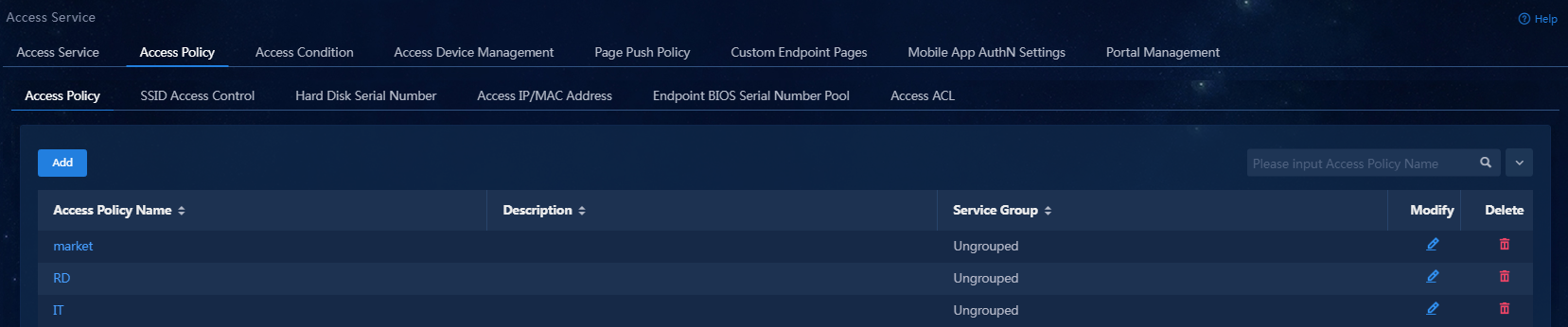
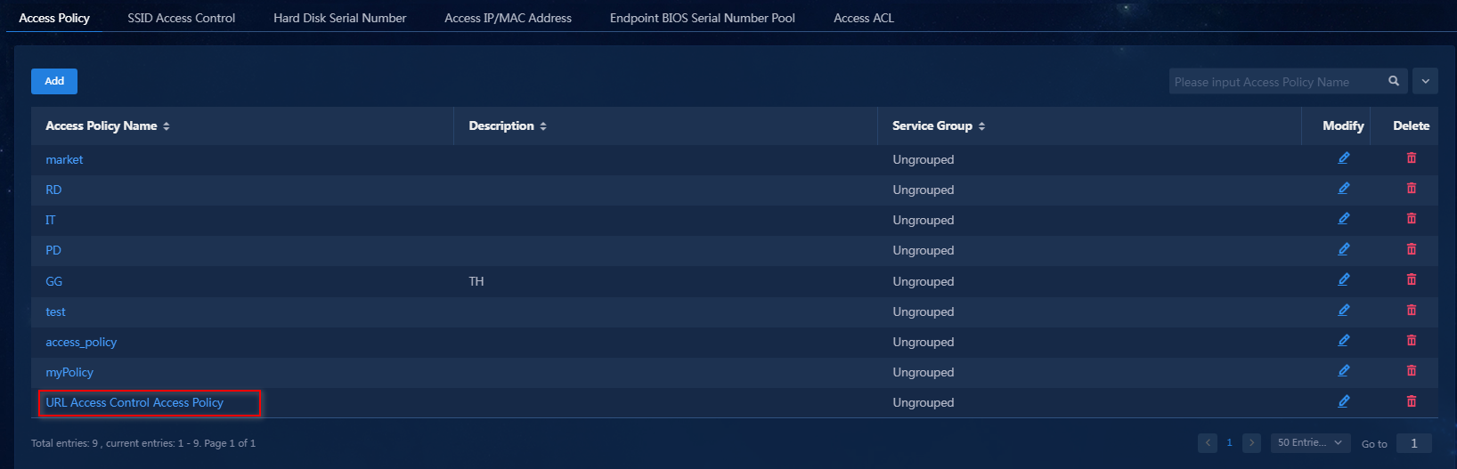
Adding an access policy
This example adds an access policy that does not perform any access control.
To add an access policy:
1. On the top navigation bar, click Automation. From the navigation pane, select User > Access Service > Access Policy > Access Policy.
Figure 33 Access policy list
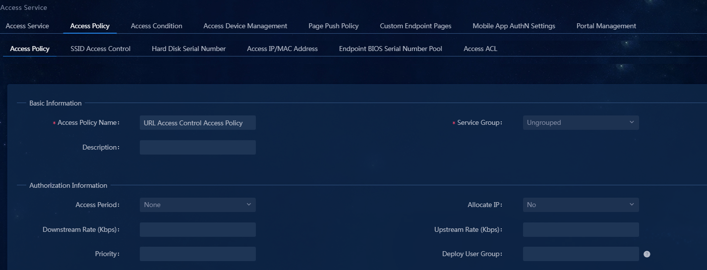
2. Click Add. On the page that opens, enter an access policy name. Use the default settings for the other parameters.
Figure 34 Adding an access policy
3. Click Confirm. Verify that the access policy has been added to the access policy list.
Figure 35 Verifying that the access policy has been added to the access policy list
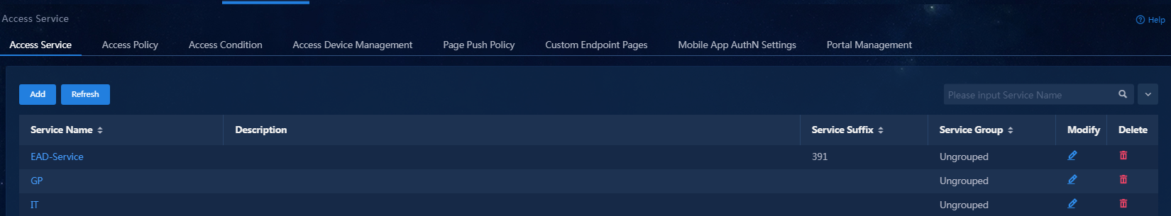
Adding an access service
1. On the top navigation bar, click Automation. From the navigation pane, select User > Access Service.
Figure 36 Access services
2. Click Add. On the page that opens, select a default access policy and a default security policy, and enter the service suffix as needed.
Figure 37 Adding an access service
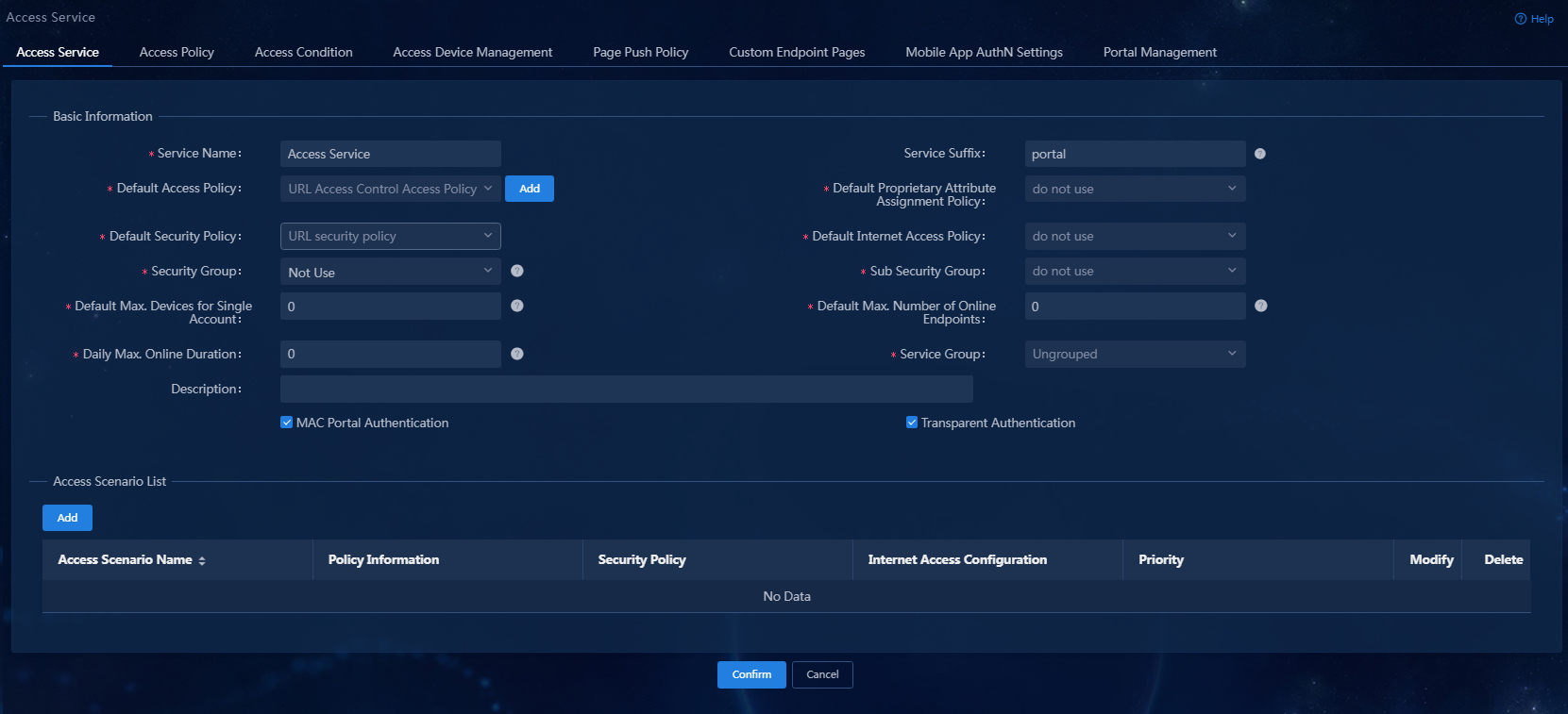
Table 1 Access service parameter description
|
Parameter |
Description |
|
Service Name |
Enter a service name, which must be unique. |
|
Service Suffix |
Enter a service suffix, which identifies the name of the domain to be used for user authentication. The service suffix, authentication username, authentication domain, and the device's RADIUS scheme command are closely related to each other. For more information about the matrix of these elements, see Table 2. |
|
Default Access Policy |
Select an access policy that has been added. |
|
Default Security Policy |
Select a security policy that has been added. |
|
Default Proprietary Attribute Assignment Policy |
Specify the default proprietary attribute assignment policy. If a user that uses the service does not match an access device group when the user accesses the network, the system deploys proprietary attributes to the access device according to the configuration of the default proprietary attribute assignment policy. |
|
Default Max. Devices for Single Account |
Specify the maximum number of endpoints to be bound to the same user account in access scenarios that are not included in the service. This field is available only when the EIP component is deployed. EIA checks the maximum number of bound endpoints for a single account in the following order: · Matched access scenario: Checks the number of bound endpoints against the maximum number limit specified in the scenario. If the number reaches the limit, EIA denies the user authentication. · Scenarios in all services: Checks the number of bound endpoints in scenarios of all assigned services for the account. If the number reaches the value of Max. Device for Single Account specified in user endpoint settings on the Automation > User > Service Parameters > Access Parameters > System Settings page, EIA denies the user authentication. |
|
Default Max. Number of Online Endpoints |
Specify the maximum number of online endpoints using the same user account in access scenarios that are not included in the service. |
|
Daily Max. Online Duration |
Specify the total duration in a day that an account can access the network by using the service. When the limit is reached, the account is forced offline and cannot access the network this day. The value can be an integer in the range of 0 to 1440 minutes. A value of 0 means no limit. |
|
Description |
Enter a description for the access service. |
|
Authentication username |
Authentication domain |
Device's RADIUS scheme command |
Service suffix on EIA |
|
X@Y |
Y |
user-name-format with-domain |
Y |
|
user-name-format without-domain |
No suffix |
||
|
X |
[Default Domain] Default domain on the device |
user-name-format with-domain |
[Default Domain] |
|
user-name-format without-domain |
No suffix |
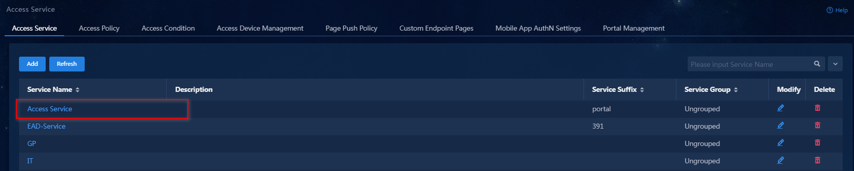
3. Click Confirm. Verify that the access service has been added to the access service list.
Figure 38 Verifying that the access service has been added to the access service list
Adding an access user
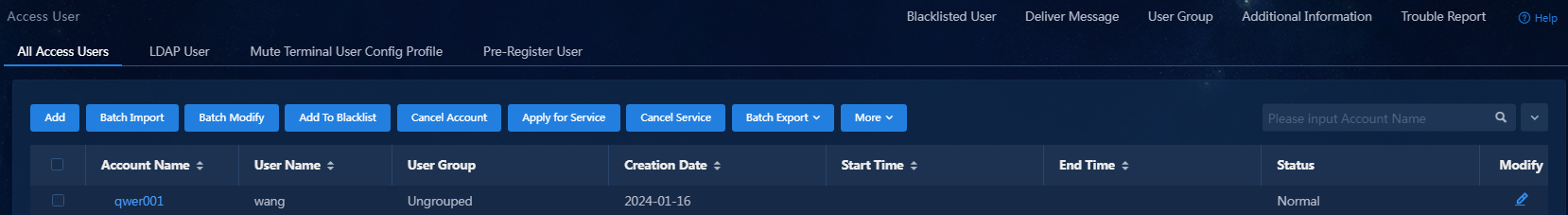
1. On the top navigation bar, click Automation. From the navigation pane, select User > Access User > All Access Users.
Figure 39 Access users
2. Click Add. On the page that opens, configure the access user parameters, as shown in Table 3.
Use the default settings for the other parameters.
Figure 40 Adding an access user
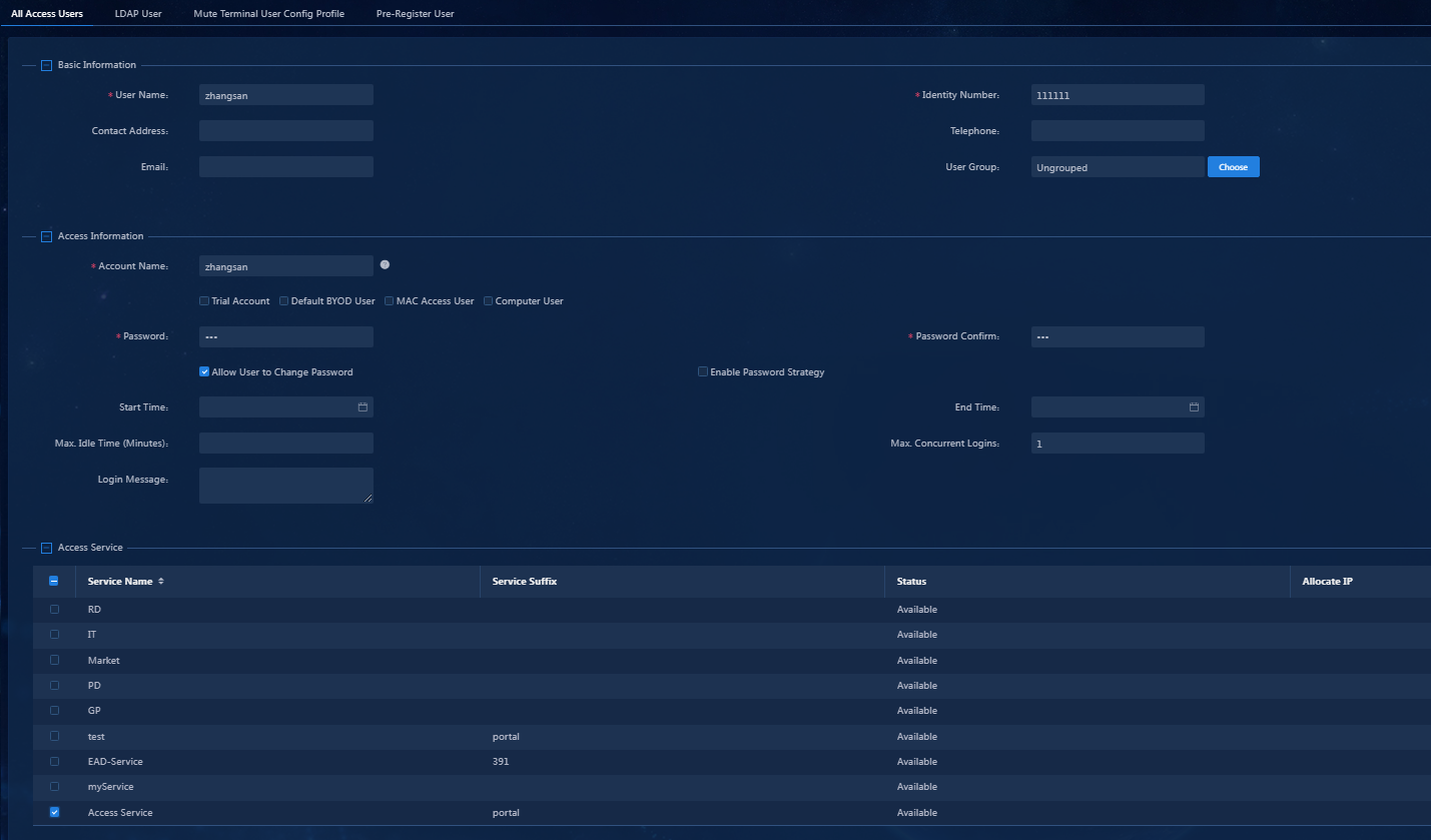
Table 3 Access user parameter description
|
Parameter |
Description |
|
Account Name |
Uniquely identifies an account user. The user uses the account name to apply for and use services. The account name is a string of up to 200 characters that cannot contain the Tab key or special characters #+/?%&=*'@\"[]()<>` |
|
Password/Password Confirm |
Enter the same password for identity verification. |
|
Allow User to Change Password |
Select whether to enable access users to modify their own password. If you do not enable this feature, the Enable Password Strategy or Forced Password Change at Next Login option is not available. |
|
Enable Password Strategy |
Determine whether access users are subject to the password control policy when changing their passwords through the client or user self-service platform. |
|
Access Service |
Depending on the user's assigned user group, the page displays a list of access services the user can apply for. You can apply for a service only after selecting the checkbox for that service. (The access service added in this manual is named Access Service. An account can apply for multiple services but cannot apply for two or more services with the same suffix. To apply for a service with an assigned IP address, you must set an IP address after selecting the service. For more information, see the online help for access service management. |
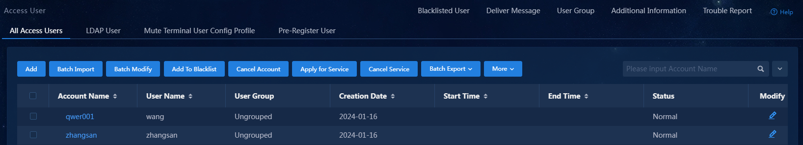
3. Click Confirm. Verify that the access user has been added to the access user list.
Figure 41 Verifying that the access user has been added to the access user list
Configuring the portal service
|
|
NOTE: This manual uses the Portal authentication method. For information about configuring the portal server, see H3C Portal Authentication (IPv4) with EIA Configuration Examples. |
Configuring an access device
Access devices control user access. Authenticated users can access the network, while unauthenticated users cannot.
The following uses the CLI window of Windows to Telnet into the access device and configure the related settings:
1. Enter system view.
<Device>system-view
System View: return to User View with Ctrl+Z.
2. Configure RADIUS policy allpermit. Both authentication and accounting servers point to EIA. The authentication port, accounting port, and shared key must be consistent with the configuration when you add an access device in EIA.
[Device]radius scheme allpermit
New Radius scheme
[Device-radius-allpermit]primary authentication 172.19.206.7 1812
[Device-radius-allpermit]primary accounting 172.19.206.7 1813
[Device-radius-allpermit]key authentication simple movie
[Device-radius-allpermit]key accounting simple movie
[Device-radius-allpermit]user-name-format with-domain
[Device-radius-allpermit]nas-ip 172.19.254.177
[Device-radius-allpermit]quit
3. Configure domain portal and associate policy allpermit. The domain name must be consistent with the suffix of the service in EIA. This example uses portal.
[Device]domain portal
[Device-isp-portal]authentication portal radius-scheme allpermit
[Device-isp-portal]authorization portal radius-scheme allpermit
[Device-isp-portal]accounting portal radius-scheme allpermit
[Device-isp-portal]quit
4. Configure the portal authentication server named myportal and set the IP address to point to EIA. Make sure the key is consistent with the configuration on EIA.
[Device]portal server myportal
New portal server added.
[Device-portal-server-myportal]ip 172.19.206.7 key simple movie
[Device-portal-server-myportal]quit
5. Specify the URL for the portal Web server as http://172.19.206.7:9092/portal, which must be consistent with the configuration on EIA. You can check the configuration on the portal homepage on the server configuration page.
[Device]portal web-server myportal
New portal web-server added.
[Device-portal-websvr-myportal]url http://172.19.206.7:9092/portal
[Device-portal-websvr-myportal]quit
6. Create a MAC binding server. Configure the IP address of the MAC binding server, which is used to record the portal authentication information of the user (username and password) and the MAC address of the user endpoint and bind them together to substitute the user in completing portal authentication.
[Device]portal mac-trigger-server mstp
[Device-portal-mac-trigger-server mstp]ip 172.19.206.7 key simple movie
7. Enable IPv4 portal authentication ono Vlan-interface 108 where GigabitEthernet1/0/16 resides and associate portal server myportal. Set the BAS-IP attribute value in the portal messages transmitted to the portal authentication server.
[Device]interface Vlan-interface 108
[Device-Vlan-interface108]portal enable method direct
[Device-Vlan-interface108]portal apply web-server myportal
[Device-Vlan-interface108]portal apply mac-trigger-server mstp
[Device-Vlan-interface108]portal bas-ip 108.108.108.1
[Device-Vlan-interface108]Portal domain portal
Verifying the configuration
To use PC for authentication:
1. Open the iNode client, and enter the username and password for authentication to come online.
2. After identity authentication, iNode controls user access to URLs, allowing access to permitted URLs and prohibiting access to denied URLs.
