| Title | Size | Downloads |
|---|---|---|
| 01-H3C EAD PC Controllable Software Group Configuration Example-book.pdf | 3.41 MB |
- Table of Contents
- Related Documents
-
| Title | Size | Download |
|---|---|---|
| book | 3.41 MB |
H3C EAD PC Controllable Software Group Management
Configuration Example
Document version: 5W100-20240314
Software version: EAD (E6204)
Copyright © 2024 New H3C Technologies Co., Ltd. All rights reserved.
No part of this manual may be reproduced or transmitted in any form or by any means without prior written consent of New H3C Technologies Co., Ltd.
Except for the trademarks of New H3C Technologies Co., Ltd., any trademarks that may be mentioned in this document are the property of their respective owners.
The information in this document is subject to change without notice.
Introduction
The PC-controllable software group defines the software, processes, services, and files that need to be inspected.
The inspection items for software/process/services/file are as follows:
· Software: Installation state.
· Process: Operation state.
· Service: Startup state.
· File: Existence state.
Usage guide
Application scenarios
This feature is applicable in enterprises, schools, or other environments that require inspection of end-system software, processes, services, and files.
Configuration example
Network configuration
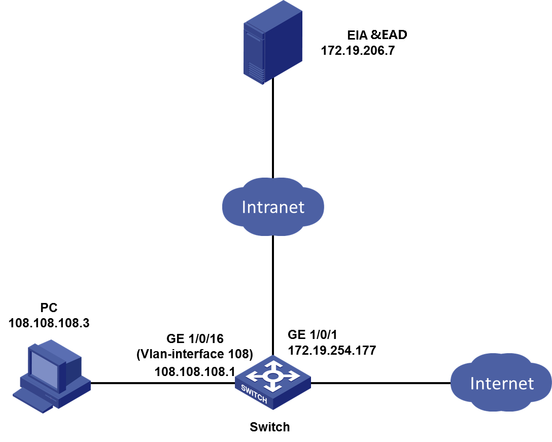
An enterprise plans to enable PC controllable software group inspection. When users access the network, they need to go through access authentication and PC controllable software group inspection.
|
|
NOTE: EAD relies on EIA. Deploy EIA before deploying EAD. |
· The IP address for the EIA&EAD server is 172.19.206.7. The way to view the IP address is as follows:
|
|
NOTE: · In a cluster, specify the northbound service virtual IP address as the IP address of the EIA/EAD server. · This section describes how to view the IP address of the EIA/EAD server. The IP addresses involved are for illustration only. |
a. Open a browser and enter https://ip_address:8443/matrix/ui to open the matrix page. ip_address is the northbound service virtual IP or node IP.
b. On the top navigation bar, click Deploy. From the navigation pane, select Clusters. Click the Cluster Parameters tab.
c. The northbound service virtual IP displayed on the page is the IP address of the EIA/EAD server.
Figure 1 Viewing the IP address of the EIA/EAD server

· The customer-facing interface on the access device (GigabitEthernet 1/0/16) belongs to VLAN 108. The IP address of VLAN-interface 108 is 108.108.108.1.
· The IP address of the PC is 108.108.108.3. You must install an operating system and the iNode client on the PC.
The software versions used in this example are as follows:
· EIA and EAD: EIA (E6204) and EAD (E6204).
· Access device: H3C S5820V2-54QS-GE.
· iNode: iNode PC 7.3 (E0585)
Procedures
This example uses portal authentication, and the configuration details are not shown. For configuration details, see the access authentication configuration example.
Configuring a PC controllable software group
On the PC controllable software group management page, you can add, edit, and delete four types of PC controllable software groups: software, process, service, and file. You can also filter PC controllable software groups by group, software, process, service, or file name.
PC controllable software group (software)
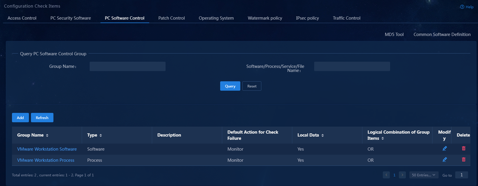
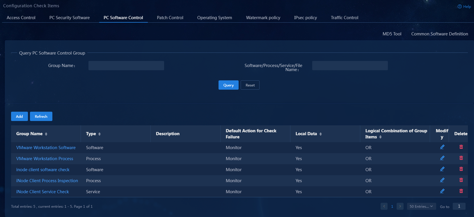
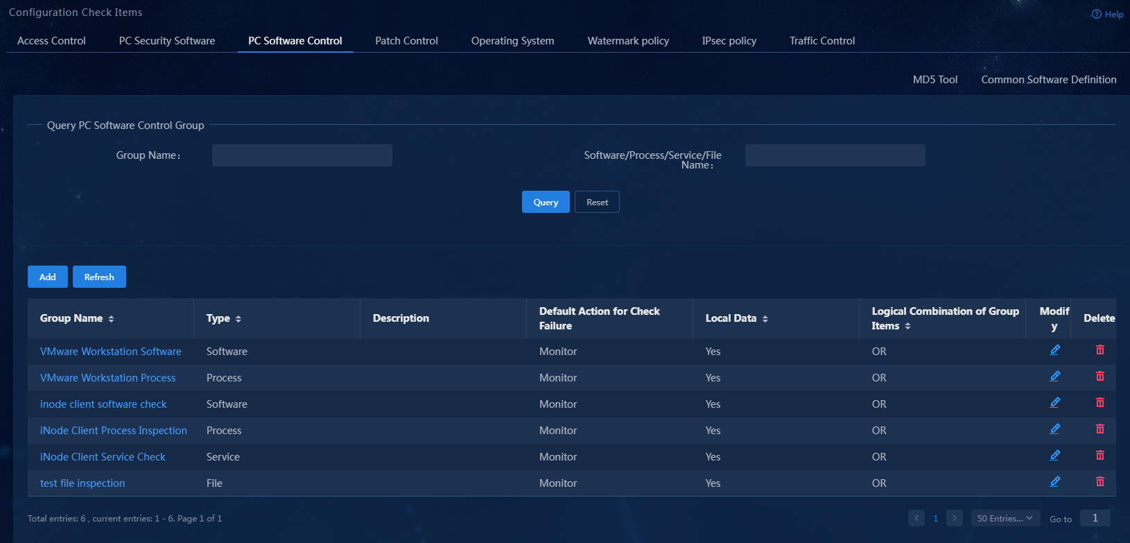
1. Select Automation > Endpoint Business > Endpoint Security > Configuration Check Items from the navigation pane, and then click the PC Software Control tab.
Figure 3 PC controllable software group page

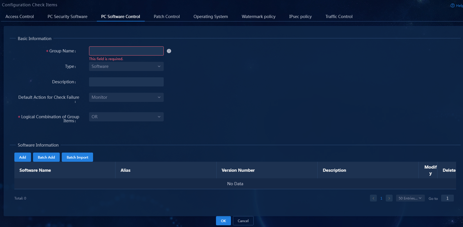
2. Click Add.
Figure 4 Adding a PC controllable software group

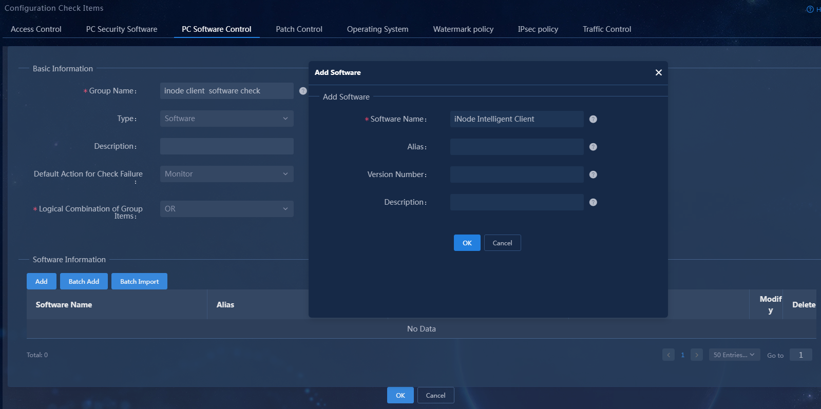
3. Select the software type, set the group name to iNode client software check. In the software information area, click Add to add software iNode Intelligent Client, keeping the default settings for other parameters.
Figure 5 Adding a software-type PC controllable software group
Parameter description:
¡ Group Name: The name cannot contain special characters {|<>/%&'",;:*}.
¡ Software Name: The software name must be consistent with the software name displayed on the control panel. The software name cannot contain {;}. The wildcards (*) can only appear at the beginning or the end of the name.
¡ Default Action for Check Failure: The default action for non-compliance during PC controllable software group inspection. If you configure the PC controllable software group to not use the global security mode, the default action for non-compliance of this PC controllable software group is the action specified by this parameter. You can configure the global security mode on the Automation > Endpoint Security > Admission Security Levels page. The global security mode takes precedence over the action specified by this parameter.
¡ Logical Combination of Group Items: Configure the interrelationships between sub-items within the PC controllable software group. The relationships between sub-items in the group can be OR or AND. OR indicates that any one of the sub-items satisfied is sufficient. AND indicates that all sub-items must be satisfied.
For more information about the parameters, see the online help.
Figure 6 Adding a soft-type PC controllable software group
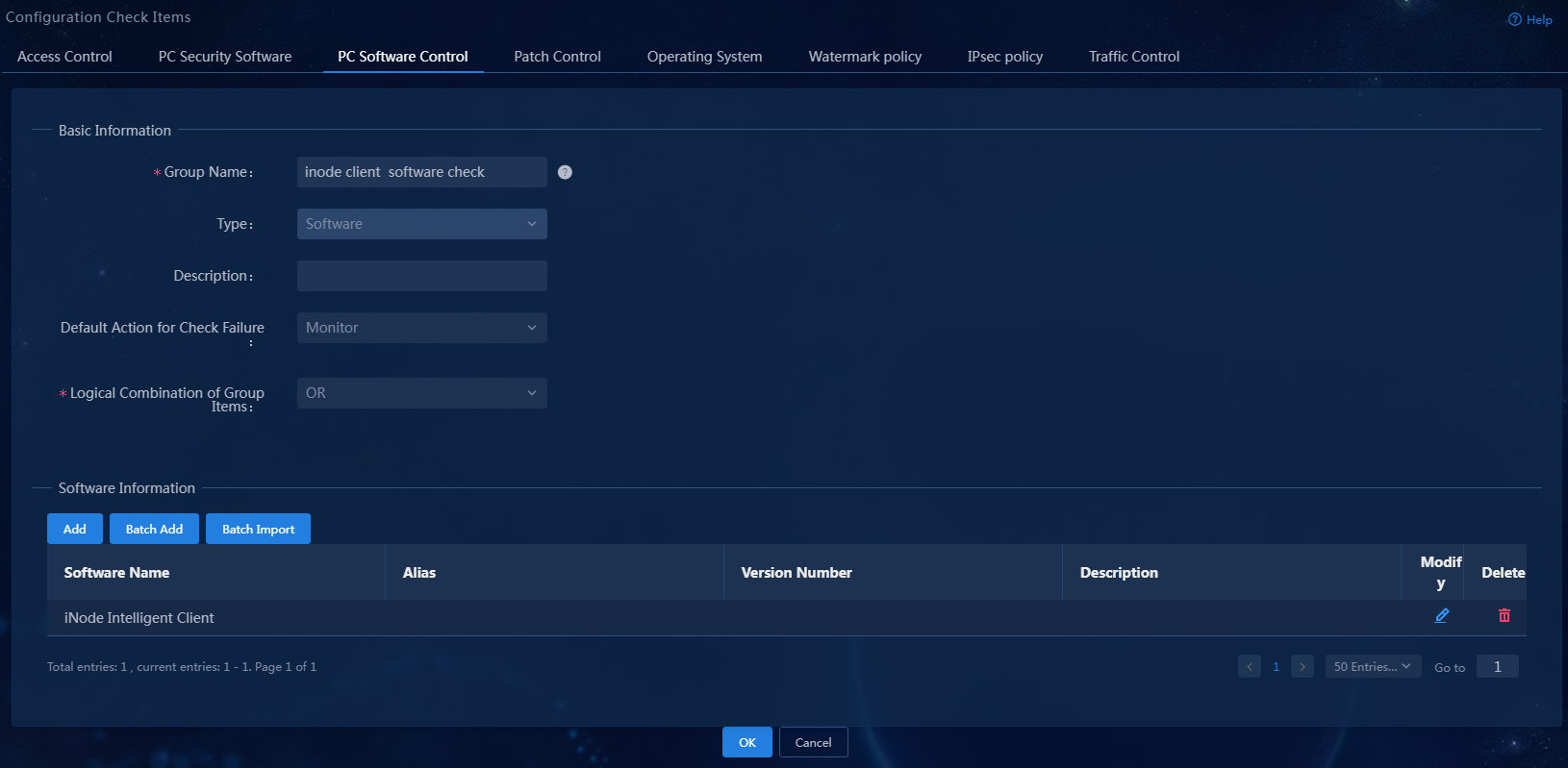
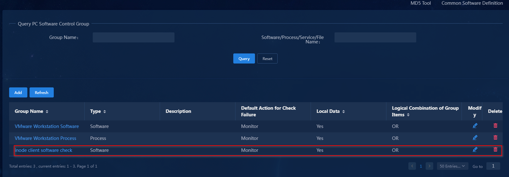
The newly added PC controllable software group is displayed in the PC controllable software group list.
Figure 7 PC controllable software group list
PC controllable software group (process)
1. Select Automation > Endpoint Business > Endpoint Security > Configuration Check Items from the navigation pane, and then click the PC Software Control tab.
Figure 8 PC controllable software group page

2. Click Add.
Figure 9 Adding a PC controllable software group

3. Select the process type, set the group name to iNode Client Process Inspection. In the process information area, click Add to add process iNode Client.exe, keeping the default settings for other parameters.
Figure 10 Adding a process-type PC controllable software group
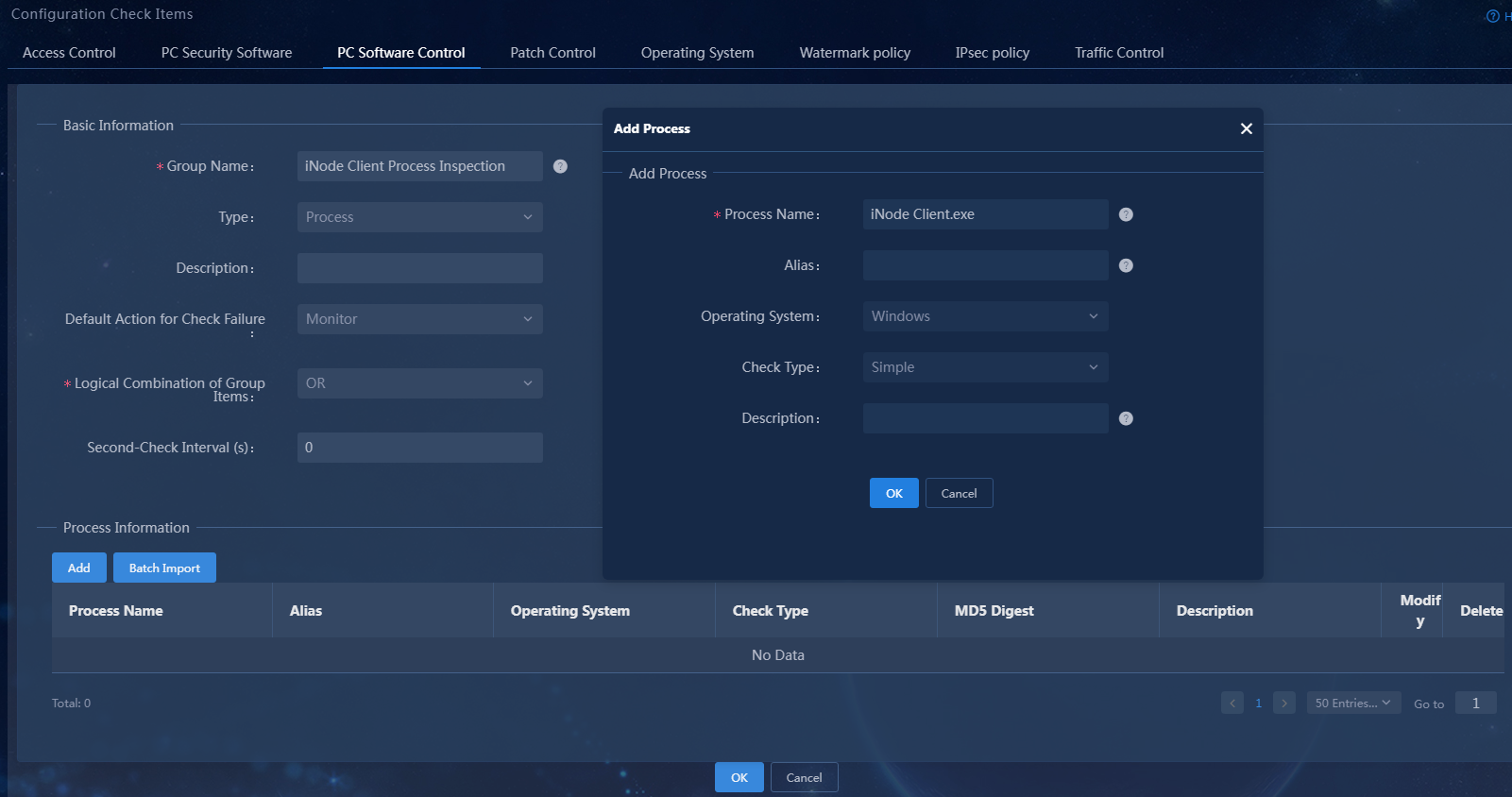
Parameter description:
¡ Group Name: The name cannot contain special characters {|<>/%&'",;:*}.
¡ Process Name: The process name cannot contain special characters {|<>/%&'",;*}.
- For a Windows operating system, the process name must be consistent with the software process name displayed on the Task Manager > Processes page.
- For a Linux operating system, the process name must be consistent with the process name in the output from the ps -ef command.
- For a Mac OS, the process name must be consistent with the process name in the output from the ps -awwx -o command.
¡ Default Action for Check Failure: The default action for non-compliance during PC controllable software group inspection. If you configure the PC controllable software group to not use the global security mode, the default action for non-compliance of this PC controllable software group is the action specified by this parameter. You can configure the global security mode on the Automation > Endpoint Security > Admission Security Levels page. The global security mode takes precedence over the action specified by this parameter.
¡ Logical Combination of Group Items: Configure the interrelationships between sub-items within the PC controllable software group. The relationships between sub-items in the group can be OR or AND. OR indicates that any one of the sub-items satisfied is sufficient. AND indicates that all sub-items must be satisfied.
For more information about the parameters, see the online help.
4. Click OK.
Figure 11 Adding a process-type PC controllable software group
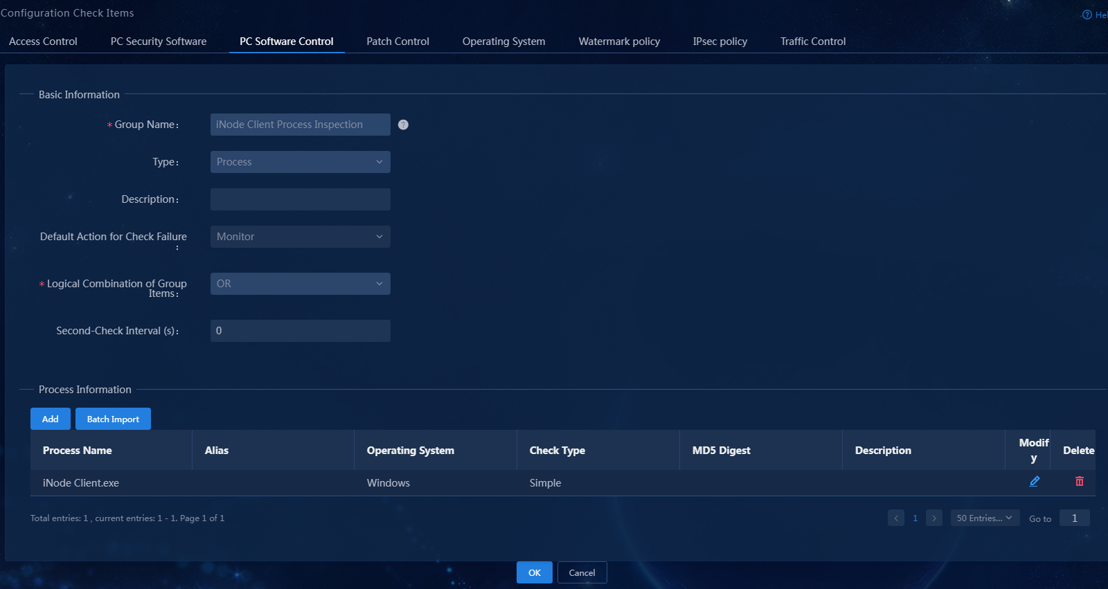
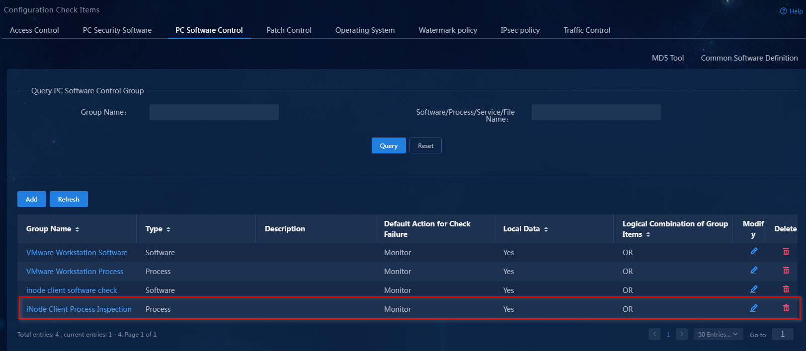
The newly added PC controllable software group is displayed in the PC controllable software group list.
Figure 12 PC controllable software group list
PC controllable software group (service)
1. Select Automation > Endpoint Business > Endpoint Security > Configuration Check Items from the navigation pane, and then click the PC Software Control tab.
Figure 13 Software Control Page for PC
2. Click Add.
Figure 14 Adding a PC controllable software group
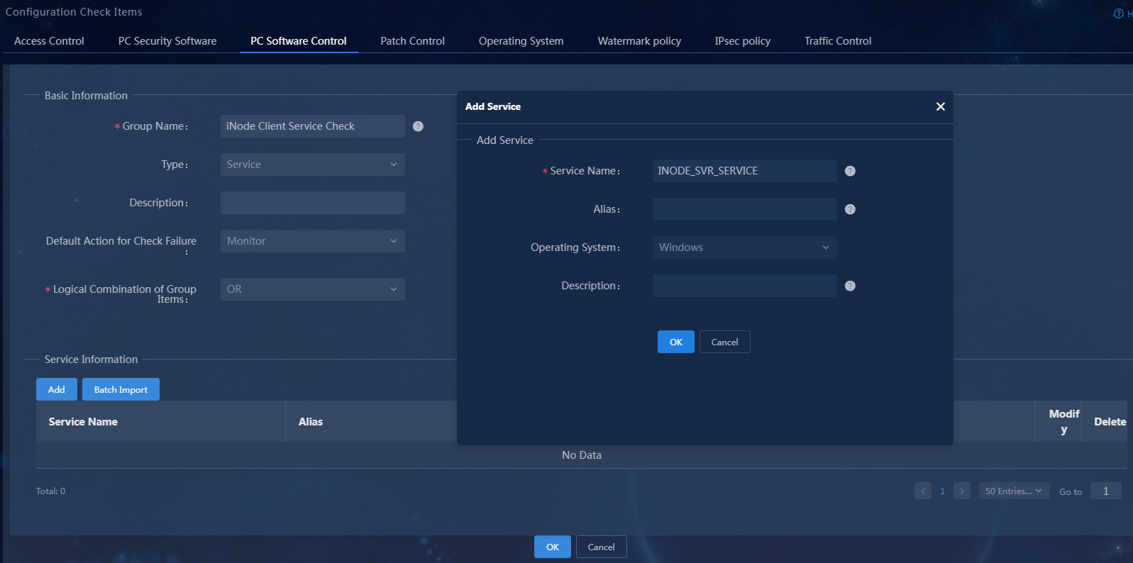
3. Select the service type, set the group name to iNode Client Service Check. In the service information area, click Add to add service INODE_SVR_SERVICE, keeping the default settings for other parameters.
Figure 15 Adding a service-type PC controllable software group
Parameter description:
¡ Group Name: The name cannot contain special characters {|<>/%&'",;:*}.
¡ Service Name: The service name cannot contain special characters {|<>/%&'\",;*}.
- For a Windows operating systems, the service name must be consistent with the service name displayed on the Control Panel > Management Tools > Services > Properties page.
- For a Linux operating system, the service name must be consistent with the service name in the output from the service --status-all command.
- For a Mac OS, the service name must be consistent with the service name in the output from service --list command.
¡ Default Action for Check Failure: The default action for non-compliance during PC controllable software group inspection. If you configure the PC controllable software group to not use the global security mode, the default action for non-compliance of this PC controllable software group is the action specified by this parameter. You can configure the global security mode on the Automation > Endpoint Security > Admission Security Levels page. The global security mode takes precedence over the action specified by this parameter.
¡ Logical Combination of Group Items: Configure the interrelationships between sub-items within the PC controllable software group. The relationships between sub-items in the group can be OR or AND. OR indicates that any one of the sub-items satisfied is sufficient. AND indicates that all sub-items must be satisfied.
For more information about the parameters, see the online help.
4. Click OK.
Figure 16 Adding a service-type PC controllable software group
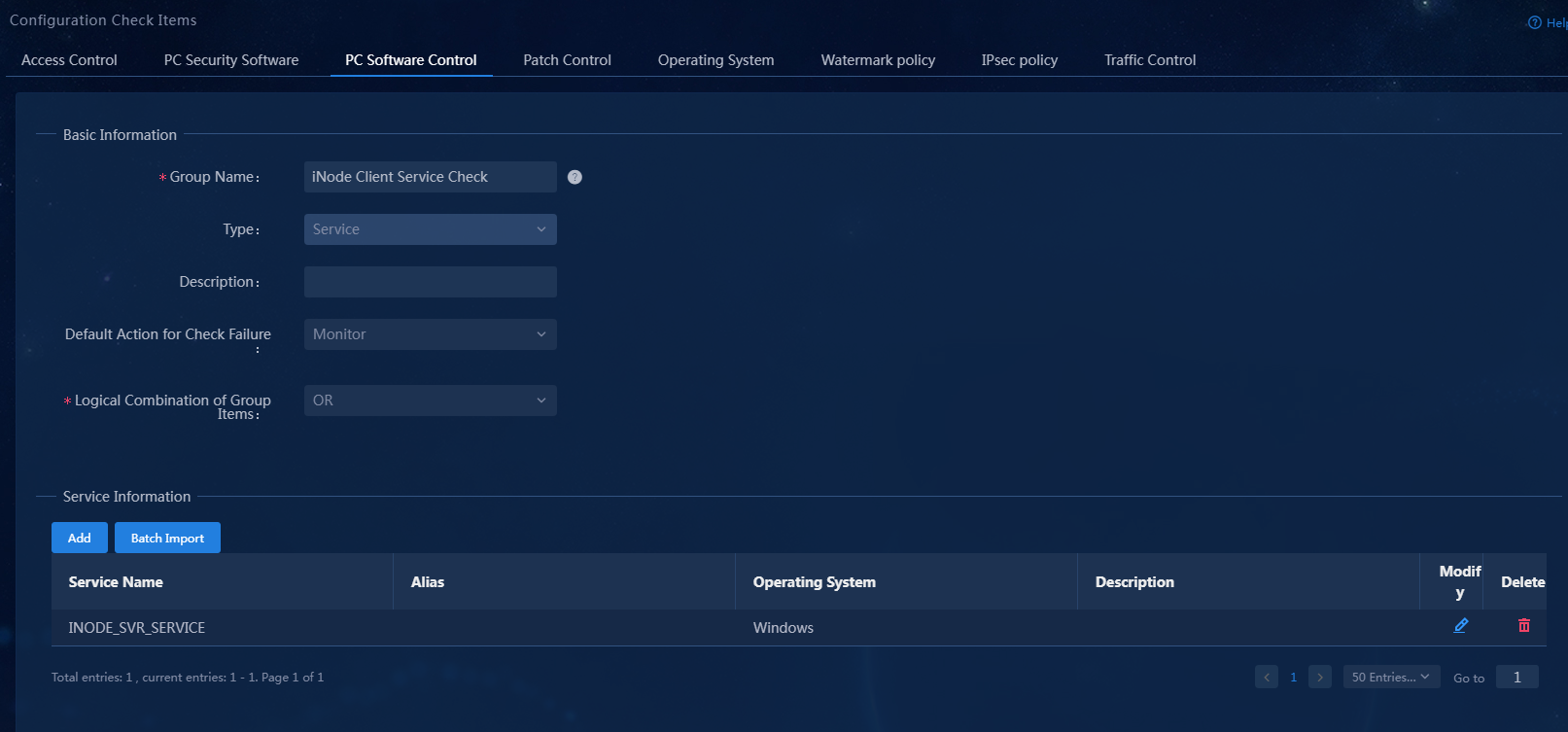
The newly added PC controllable software group is displayed in the PC controllable software group list.
Figure 17 PC controllable software group list
PC controllable software group (file)
1. Select Automation > Endpoint Business > Endpoint Security > Configuration Check Items from the navigation pane, and then click the PC Software Control tab.
Figure 18 Software control page for PC

2. Click Add.
Figure 19 Adding a PC controllable software group

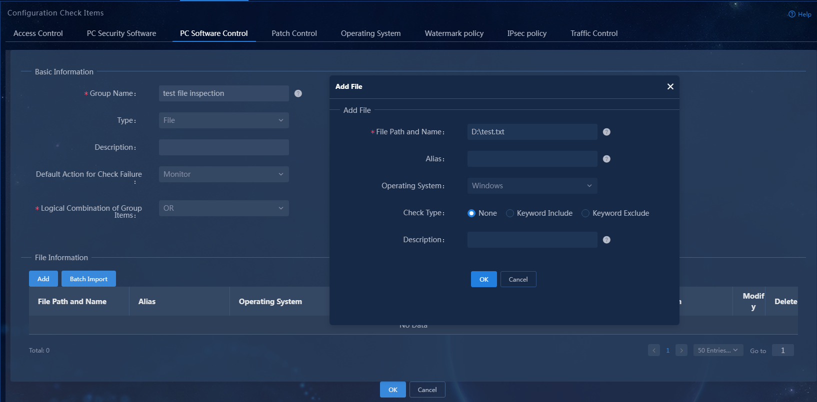
3. Select the file type, set the group name to test file inspection. In the file information area, click Add to add file D:\test.txt. You can configure the keyword check type (including none, keyword include, and keyword exclude), keyword type (including visible string and hexadecimal/binary), and the keyword content.
Figure 20 Adding a file-type PC controllable software group
Parameter description:
¡ Group Name: The name cannot contain special characters {|<>/%&'",;:*}.
¡ File Path and Name: The file path and name represent the absolute path and the filename. For Windows, a filename must start with "x:" (where x stands for the disk name). For Linux and Mac OS, a filename must start with "/". If the filename includes an extension, the extension must also be specified. The filename cannot contain special characters {*?;|#<>}.
¡ Default Action for Check Failure: The default action for non-compliance during PC controllable software group inspection. If you configure the PC controllable software group to not use the global security mode, the default action for non-compliance of this PC controllable software group is the action specified by this parameter. You can configure the global security mode on the Automation > Endpoint Security > Admission Security Levels page. The global security mode takes precedence over the action specified by this parameter.
¡ Logical Combination of Group Items: Configure the interrelationships between sub-items within the PC controllable software group. The relationships between sub-items in the group can be OR or AND. OR indicates that any one of the sub-items satisfied is sufficient. AND indicates that all sub-items must be satisfied.
¡ Keyword Type: If the keyword type is visible string, only text files are supported. DOC and XLS files are not supported. If the keyword type is hexadecimal/binary, all file types are supported. When the keyword type is a visible string, it cannot contain {+;}. When the keyword type is hexadecimal/binary, it can only contain 0 to 9 and A to F, and its length must be an even number.
For more information about the parameters, see the online help.
4. Click OK.
Figure 21 Adding a file-type PC controllable software group
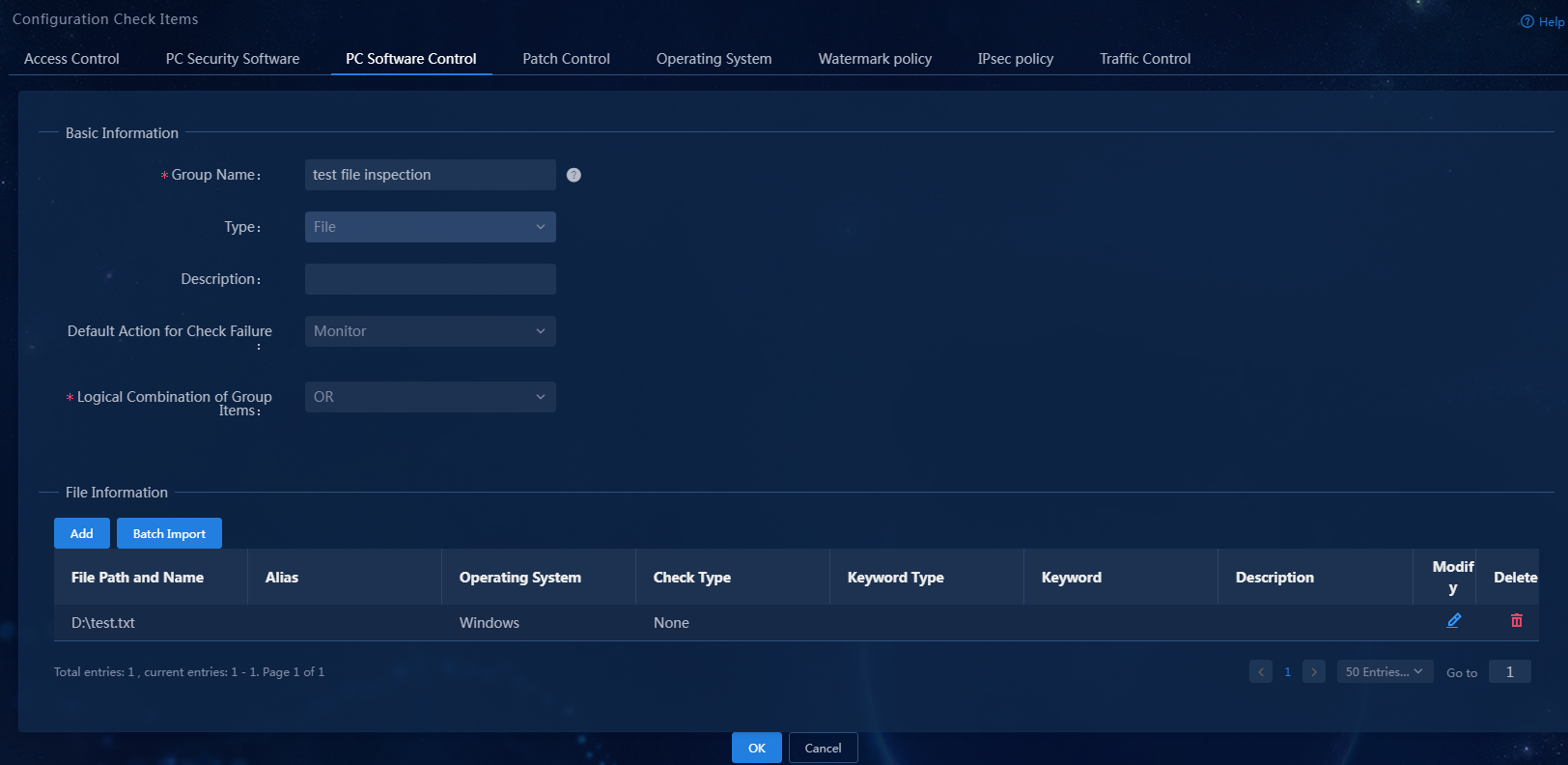
The newly added PC controllable software group is displayed in the PC controllable software group list.
Figure 22 PC controllable software group list
Configuring endpoint security management
Adding an admission security level
1. Select Automation > Endpoint Business > Endpoint Security > Admission Security Levels from the navigation pane.
Figure 23 Admission security level page

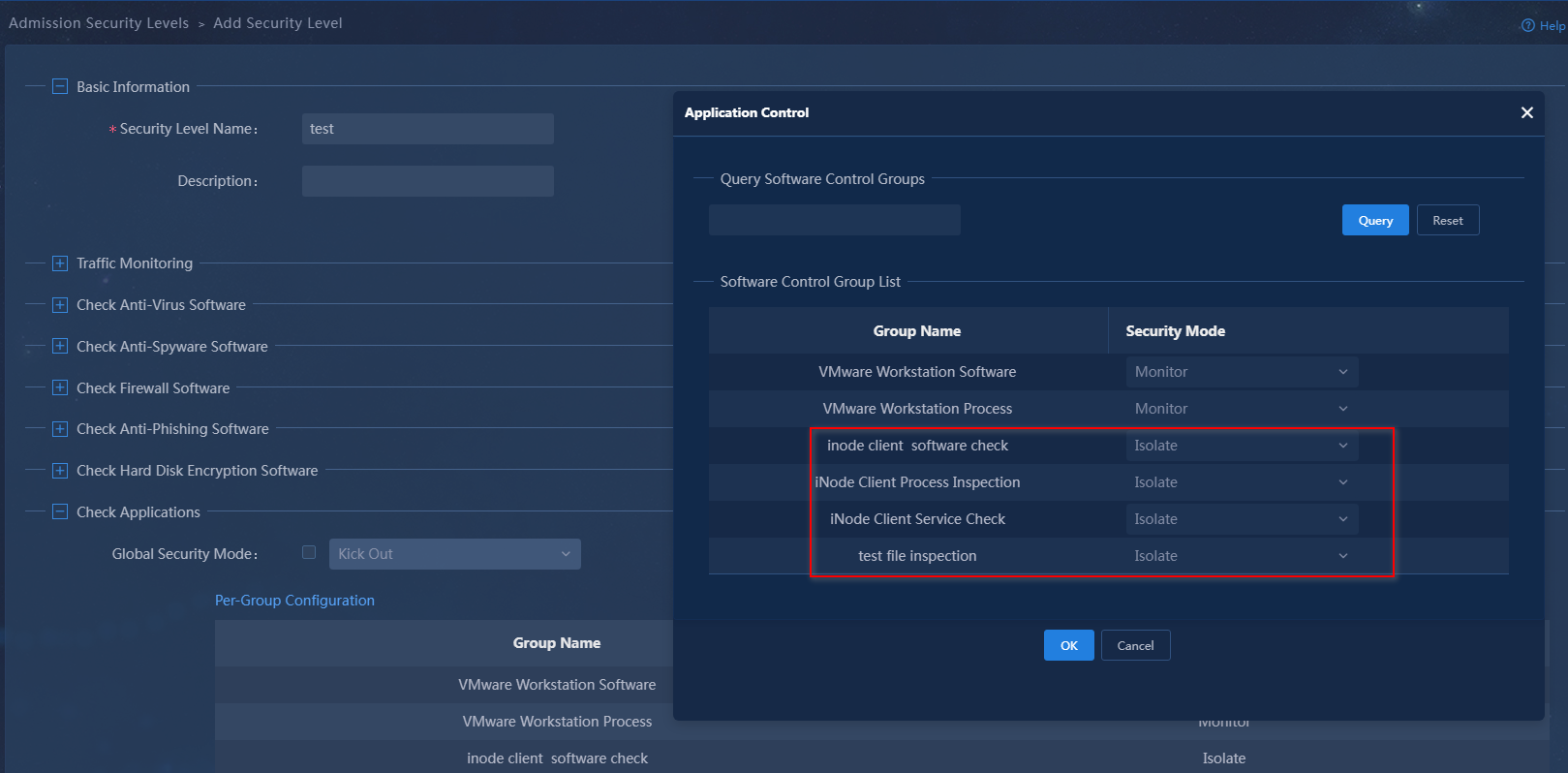
2. Click Add. In the basic information area, set the security level name to test. Configure the security mode applied when a controllable software group fails inspection. You can configure a global security mode or configure the items one by one.
¡ Global Security Mode: All controllable software groups use this security mode.
¡ Item by item configuration: Configure a security mode for each controllable software group separately.
In this example, configure the PC controllable software groups item by item. Select the isolation mode for iNode client software check, iNode Client Process Inspection, iNode Client Service Check, and test file inspection.
Figure 24 Adding an admission security level
Adding an admission security policy
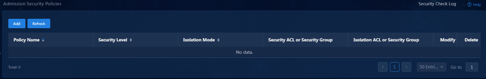
1. Select Automation > Endpoint Business > Endpoint Security > Admission Security Policies from the navigation pane.
Figure 25 Admission security policy page
2. Click Add. In the basic information area, set the security policy name to test and the security level to monitor mode. In the PC area, select controllable software group inspection. You can configure the controllable software group on an item-by-item basis.
In this example, set the check type to install only for iNode client software inspection, running required for iNode client process inspection, startup required for iNode client service inspection, and existence required for test file inspection. For a software-type PC controllable software group, you can configure a server address. If the security check fails, the iNode client will prompt the user to visit the server for recovery, as shown in Figure 27.
Figure 26 Adding an admission security policy
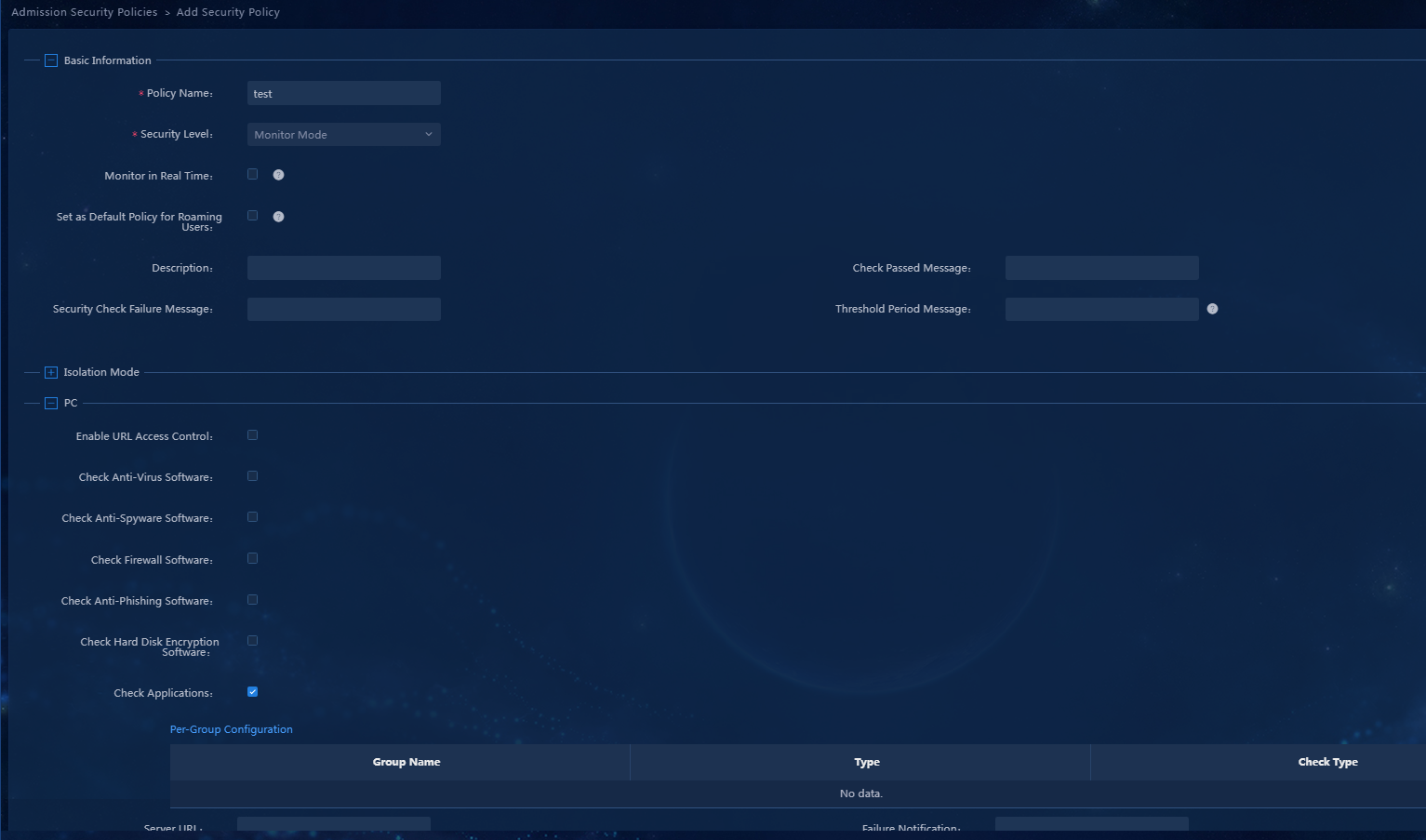
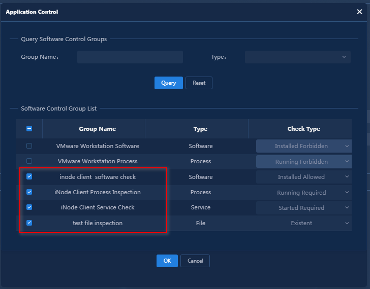
Figure 27 Adding an admission security policy-checking controllable software group-item-by-item configuration
Parameter description:
¡ Check PC Controllable Software Group: Check whether the software and files used on the user terminal comply with the controllable software group check requirements. The controllable software group check types include installation, running, startup, and existence. For a software-type group, the check rule can be set to installation forbidden, installation required, or installation only. For a process-type group, the check rule can be set to running required or running forbidden. For a service-type group, the check rule can be set to startup required or startup forbidden. For a file-type group, the check rule can be set to existence required or existence forbidden.
¡ Server URL: If the software used by the user during network access does not meet the requirements, iNode will prompt the user to visit the configured server for recovery. However, for processes, services, and files that fail the inspection, the server cannot provide recovery.
¡ Security Threshold: When a user fails the security check, the number of failures accumulates. When this number reaches the security threshold, the system will take the corresponding action, such as logoff or isolation. After a user passes the security check, the accumulated failure count of the user will be reset. If you set the threshold to 0, the system takes the corresponding action (logoff or isolation) immediately.
¡ The number of failures accumulates only when the terminal fails the security authentication or re-authentication, and does not accumulate in real-time monitoring.
For more information about the parameters, see the online help.
Configuring EIA services
Adding access devices
Add an access device to establish a link between the EIA server and the access device.
To add an access device:
1. Select Automation > User > Access Service from the navigation pane.
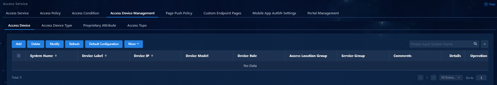
2. Click the Access Device Management tab.
Figure 28 Access device management page
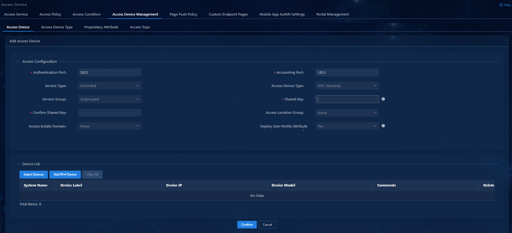
3. Click Add.
Figure 29 Adding an access device
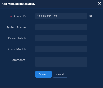
4. Click Add IPv4 Device in the Device List area.
5. Enter the IP address and name of the access device, and then click Confirm.
The IP address of the access device must meet the following requirements:
¡ If you have executed the nas ip command when configuring the RADIUS scheme on the access device, specify that configured NAS IP.
¡ If you have not executed the nas ip command, specify the IP address of the interface that connects the access device to the EIA server (or specify the IP address of the VLAN interface to which the interface belongs).
Figure 30 Manually adding an access device
6. Configure the public parameters as follows:
¡ Authentication Port: Specify the port on which EIA listens to RADIUS authentication messages. The port must be consistent with the authentication port configured on the access device through CLI. The default port is 1812.
¡ Accounting Port: Specify the port on which EIA listens to RADIUS accounting messages. The port must be consistent with the accounting port configured on the access device through CLI. The default port is 1813.
|
|
NOTE: In the current software version, the EIA server must act as both the authentication and accounting servers. You cannot configure the EIA server to act as only the authentication or accounting server. |
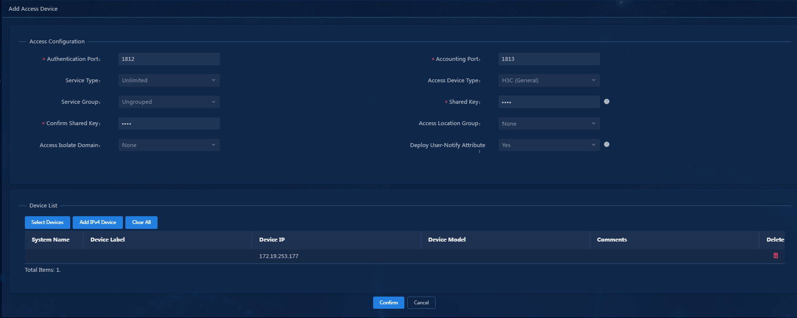
¡ Shared Key/Confirm Shared Key: Enter and confirm the shared key. When the access device cooperates with EIA for authentication, they use this key for mutual validation. The key must be consistent with the shared key configured on the access device through CLI. If the key is displayed in plain text, you only need to enter the shared key once. In this example, set the shared key to movie.
¡ Keep the default settings for other parameters.
Figure 31 Configuring public parameters
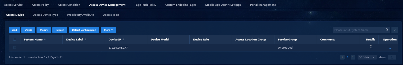
7. Click Confirm. You can view the access device in the access device list.
Figure 32 Viewing the added access device
Adding an access policy
Configure an access policy without any access control.
To add an access policy:
1. Select Automation > User > Access Service from the navigation pane.
2. Click the Access Policy tab.
Figure 33 Access policy management
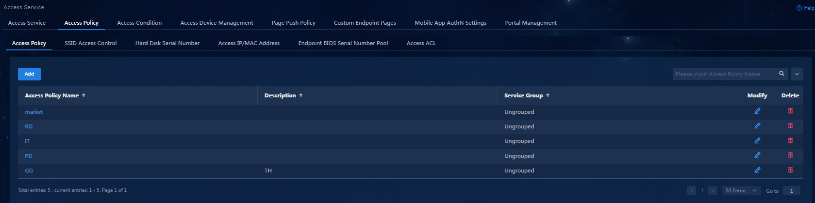
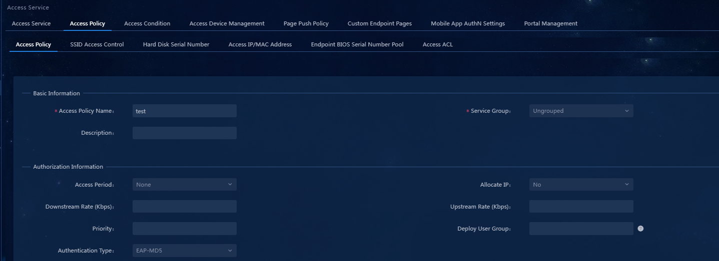
3. Click Add. Because no access control is required, you just need to enter the access policy name and keep other parameters at their default values.
Figure 34 Adding an access policy
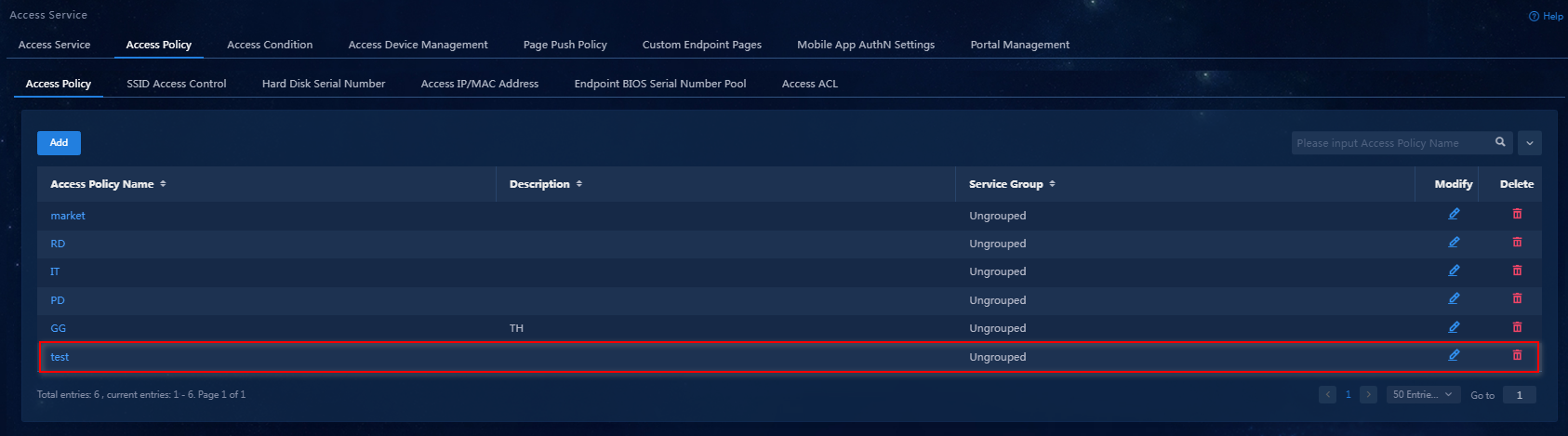
4. Click Confirm. You can view the newly added access policy in the access policy list.
Figure 35 Viewing the newly added access policy
Adding an access service
1. Select Automation > User > Access Service from the navigation pane.
Figure 36 Access service management
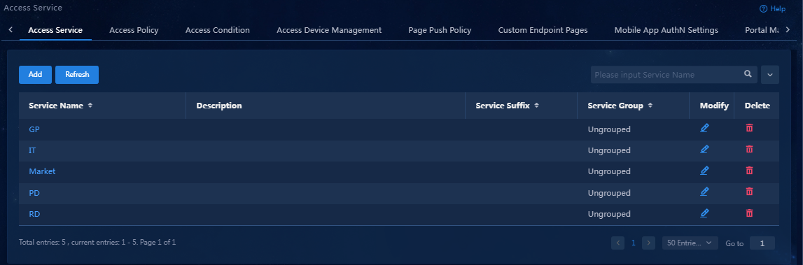
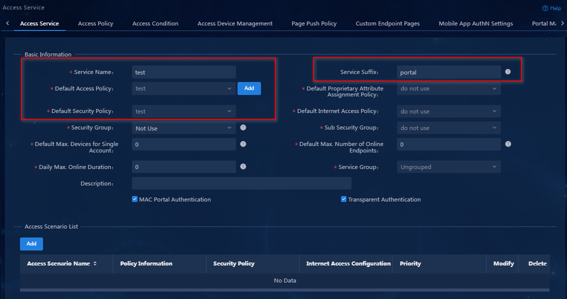
2. Click Add.
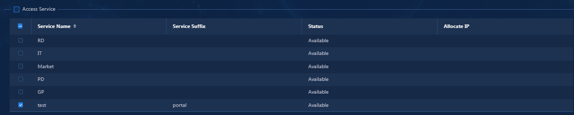
3. Configure a service name, select the preconfigured access policy test and security policy test as the default service policy and the default security policy, and set the service suffix to portal.
Figure 37 Adding an access service
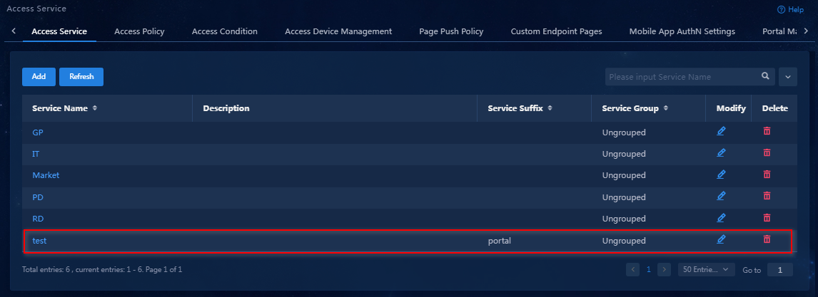
4. Click Confirm. You can view the newly added access service in the access service list.
Figure 38 Viewing the newly added access service
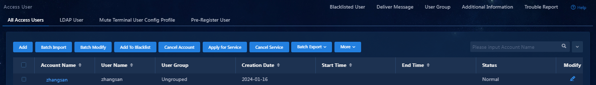
Adding an access user
1. Select Automation > User > Access User from the navigation pane.
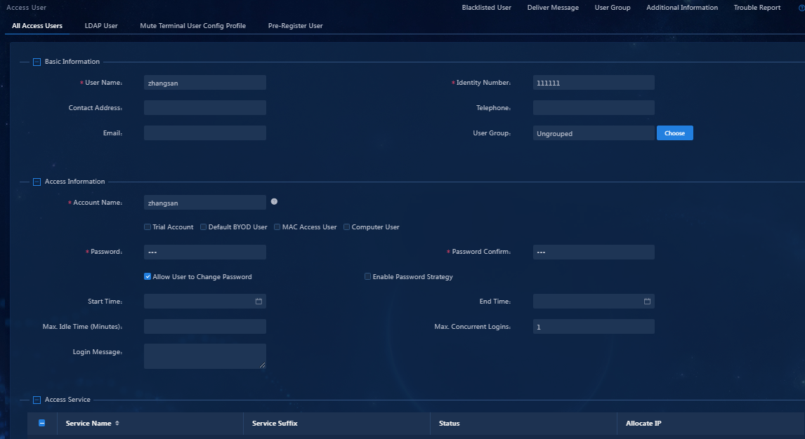
2. Click Add.
Parameter description
¡ Account Name: Uniquely identifies a user. It must be distinct from existing names, and cannot contain special characters #+/?%&=*'@\"[]()<>` or the TAB key. The maximum length is 200 characters. The account name can contain spaces. Once the account is successfully created, the account name cannot be changed. Therefore, this field is not configurable on the user editing page.
¡ Password: A password is used for identity verification and cannot be empty, with a maximum length of 32 characters.
¡ Allow User to Change Password: Select whether to allow users to modify their own passwords. If you do not select this option, the password strategy and change password at next login options are unavailable.
¡ Enable Password Strategy: Select whether users are restricted by the password control strategy when they change passwords through the client or self-service platform.
¡ Access Service: Select access services for the user. The available access services depend on the user's user group. An account can apply for multiple services but cannot apply for multiple services with the same suffix. If the IP address allocation service is selected, you need to configure the user IP address. For more service information, see the access service management online help.
Figure 40 Adding an access user
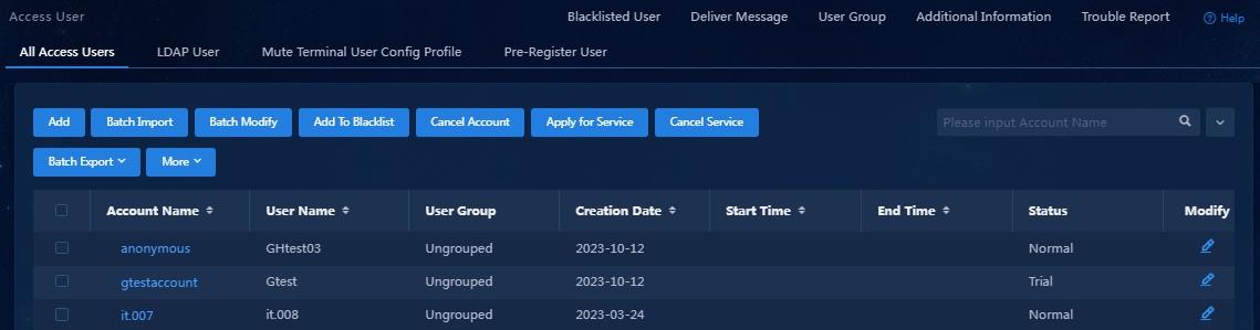
3. Click Confirm. You can view the newly added access user in the access user list.
Figure 41 Viewing the newly added access user
Configuring the access device
An access device is used to control user access. A user can access the network only after the user passes authentication.
This example uses the Windows CLI to telnet to the access device for configuration.
1. Enter system view.
<Device>system-view
System View: return to User View with Ctrl+Z.
2. Configure the RADIUS policy allpermit. Configure EIA to act as both the authentication and accounting servers. The authentication port, accounting port, and shared key must be consistent with the configuration in EIA.
[Device]radius scheme allpermit
New Radius scheme
[Device-radius-allpermit]primary authentication 172.19.206.7 1812
[Device-radius-allpermit]primary accounting 172.19.206.7 1813
[Device-radius-allpermit]key authentication simple movie
[Device-radius-allpermit]key accounting simple movie
[Device-radius-allpermit]user-name-format with-domain
[Device-radius-allpermit]nas-ip 172.19.254.177
[Device-radius-allpermit]quit
3. Configure the domain named portal, and apply policy allpermit. The domain name must be consistent with the service suffix in EIA (this section uses portal as an example).
[Device]domain portal
[Device-isp-portal]authentication portal radius-scheme allpermit
[Device-isp-portal]authorization portal radius-scheme allpermit
[Device-isp-portal]accounting portal radius-scheme allpermit
[Device-isp-portal]quit
4. Configure portal authentication server named myportal, set its IP address to the IP address of EIA. The key must be consistent with the configuration on EIA.
[Device]portal server myportal
New portal server added.
[Device-portal-server-myportal]ip 172.19.206.7 key simple movie
[Device-portal-server-myportal]quit
5. Set the portal web server's URL to http://172.19.206.7:9092/portal, which must be consistent with the configuration on EIA. You can view it on the portal homepage of the server configuration page.
[Device]portal web-server myportal
New portal web-server added.
[Device-portal-websvr-myportal]url http://172.19.206.7:9092/portal
[Device-portal-websvr-myportal]quit
6. Bind the MAC address to the server's IP address. The server records and binds the user's portal authentication information (including username and password) and client MAC address to complete portal authentication for the user.
[Device]portal mac-trigger-server mstp
[Device-portal-mac-trigger-server mstp]ip 172.19.206.7 key simple movie
7. Enable the direct-mode portal service on VLAN-interface 108 for interface GigabitEthernet 1/0/16, and reference portal web server myportal. Configure the BAS-IP attribute value in the portal messages sent to the portal authentication server.
[Device]interface Vlan-interface 108
[Device-Vlan-interface108]portal enable method direct
[Device-Vlan-interface108]portal apply web-server myportal
[Device-Vlan-interface108]portal apply mac-trigger-server mstp
[Device-Vlan-interface108]portal bas-ip 108.108.108.1
[Device-Vlan-interface108]Portal domain portal
Verifying the configuration
1. Use the user account zhangsan to access the iNode client for authentication.
2. The iNode client performs a security check on the user account. The security state of the account is secure, the account has passed the security check, and the account can access the network resources.
