- Released At: 21-10-2024
- Page Views:
- Downloads:
- Table of Contents
- Related Documents
-
|
|
|
Deployment Guide |
|
|
|
|
Document version: 5W101-20241018
Copyright © 2024 New H3C Technologies Co., Ltd. All rights reserved.
No part of this manual may be reproduced or transmitted in any form or by any means without prior written consent of New H3C Technologies Co., Ltd.
Except for the trademarks of New H3C Technologies Co., Ltd., any trademarks that may be mentioned in this document are the property of their respective owners.
The information in this document is subject to change without notice.
Contents
About the SeerEngine-Campus controller
Standalone deployment restrictions
Application installation packages
Deployment procedure at a glance
Installation and deployment tasks at a glance
Deploying SeerEngine-Campus and vDHCP
Registering and installing licenses
Installing the activation file on the license server
Scaling out the controller from standalone mode to cluster mode
About the SeerEngine-Campus controller
SeerEngine-Campus is an SDN controller designed for the application-driven campus network. From a unified GUI, SeerEngine-Campus offers compressive campus network management capabilities, including zero-touch device deployment, user authentication, access control, micro-segmentation, and service orchestration.
Terms
· Matrix—Docker containers-orchestration platform based on Kubernetes. On this platform, you can build Kubernetes clusters, deploy microservices, and implement O&M monitoring of systems, Docker containers, and microservices.
· Master node—Master node in the cluster. A cluster must contain three master nodes. If you deploy Unified Platform on a single node, that node is the master node. The cluster selects one master node as active master node automatically and the others operate as standby master nodes. When the active master node fails, the cluster selects a new active master from the standby master nodes to take over to ensure service continuity.
¡ Active master node—Manages and monitors all nodes in the cluster. The northbound service VIP is assigned to the active master node. All master nodes are responsible for service operation.
¡ Standby master node—Standby master nodes are only responsible for service operation.
· Worker node—Service node in the cluster. Worker nodes are only responsible for services and do not participate in active master node selection. When the CPU and memory usage is high, service responses are slow, or the number of pods reaches or approaches 300 on master nodes, you can add worker nodes to improve the cluster performance and service processing capability.
· Graphical User Interface (GUI)—A type of user interface through which users interact with electronic devices via graphical icons and other visual indicators.
· Redundant Arrays of Independent Disks (RAID)—A data storage virtualization technology that combines many small-capacity disk drives into one large-capacity logical drive unit to store large amounts of data and provide increased reliability and redundancy.
Features
SeerEngine-Campus provides the following features:
· Zero-touch device deployment—Provides fully automated underlay network deployment. Network devices can be automatically configured in plug and play mode, which frees the administrator from the tedious, error-prone tasks of node-by-node device configuration.
· User authentication—Supports various user authentication methods, including 802.1X, MAC authentication, and MAC portal authentication.
· Access control—Enforces access control on users based on their user group membership.
· Micro-segmentation—Decouples security groups from virtual networks, enabling service orchestration and deployment across management domains.
Deployment modes
SeerEngine-Campus can be deployed only as a containerized component on Unified Platform through the Unified Platform GUI or the convergence deployment page of Matrix. Before deploying SeerEngine-Campus on a server, you must deploy Matrix and Unified Platform on the server first. See H3C Unified Platform Deployment Guide for the deployment procedure.
|
|
NOTE: As a best practice, install and deploy SeerEngine-Campus E6801 and later versions on the convergence deployment page of Matrix. |
Preparing for installation
Software package verification
Before installing the software, first perform MD5 verification on each software package to ensure its integrity and correctness.
1. Identify the uploaded installation packages.
[root@node1~]# cd /opt/matrix/app/install/packages/
[root@node1~]# ls
BMP_Report_E0722_x86.zip UDTP_Core_E0722_x86.zip
…
2. Obtain the MD5 value of an installation package, for example, UDTP_Core_E0722_x86.zip.
[root@node1~]# md5sum UDTP_Core_E0722_x86.zip
2b8daa20bfec12b199192e2f6e6fdeac UDTP_Core_E0722_x86.zip
3. Compare the obtained MD5 value with the MD5 value released with the software. If they are the same, the installation package is correct.
Component dependencies
You can deploy vDHCP, EIA, and WSM servers in addition to the SeerEngine-Campus component. The vDHCP servers are required and the other servers are optional.
DHCP servers are used for assigning IP addresses to network devices during the zero-touch deployment process and to endpoint users requesting network access on the campus network.
You can deploy one DHCP server in standalone mode, or deploy two DHCP servers in cluster mode for high availability.
The SeerEngine-Campus network supports Microsoft DHCP servers and vDHCP servers, of which vDHCP servers are more commonly used. The vDHCP server is provided by Unified Platform as a public service component.
To use Microsoft DHCP servers, see the related document for the deployment procedure.
To use vDHCP servers, deploy the vDHCP Server component together with SeerEngine-Campus from Unified Platform.
The EIA component manages endpoint authentication and access.
The WSM component monitors and configures wireless devices.
Standalone deployment restrictions
The following restrictions apply to standalone SeerEngine-Campus deployments:
· The remote backup function must be enabled on the standalone SeerEngine-Campus controller. This function allows the controller to back up its configuration and data to a remote server periodically (typically once in a couple of days). In case that SeerEngine-Campus redeployment is required, you can restore the most recent backup files for the system with minimal data loss.
· Failures of server hardware components such as physical drives or RAID controllers cannot be recovered by rebooting the server. The SeerEngine-Campus service will be affected or unavailable until the faulty hardware or server is replaced. However, the time required for the replacement cannot be directly evaluated since it might involve purchasing the replacement components.
Installation packages
Before the deployment, obtain the installation packages for the SeerEngine-Campus, vDHCP Server, EIA Server, and WSM Server components.
Table 1 Installation packages for SeerEngine-Campus and vDHCP Server
|
Scenario |
Component |
Component installation package |
|
Campus network |
SeerEngine-Campus |
SeerEngine_CAMPUS-version-MATRIX.zip |
|
vDHCP Server |
vDHCPS_version.zip |
|
|
EIA Server |
EIA-version.zip |
|
|
WSM Server |
WSM-version.zip |
Server requirements
Hardware requirements
SeerEngine-Campus can be deployed on a single server or on a cluster of servers. You can deploy SeerEngine-Campus on physical servers or on VMs.
The controller supports the following deployment modes:
· Deploy the controller separately.
· Deploy the controller together with SeerAnalyzer on a server.
· Deploy SeerAnalyzer separately.
This section describes the hardware requirements when the controller is deployed separately.
Deploying the controller on physical servers
|
Item |
Requirements |
|
Drive |
The drives must be set up in RAID 1, 5, or 10 mode. · System drive: 7.2K RPM SATA/SAS HDDs, with a size of 2.4 TB or above in RAID setup. · etcd drive: 7.2K RPM SATA/SAS HDDs, with a size of 50 GB or above in RAID setup. (Installation path: /var/lib/etcd.) · Storage controller: 1GB cache, power fail protected with a supercapacitor installed. |
|
NIC |
· Non-bonding mode: ¡ 1 × 1 Gbps or above Ethernet port. ¡ 2 × 1 Gbps or above Ethernet ports if SeerAnalyzer is deployed. As a best practice, deploy 1 × 10 Gbps or above Ethernet port. · Bonding mode (recommended mode: mode 2 or mode 4): 2 × 1 Gbps Linux bonding interfaces. 2 × 1 Gbps Linux bonding interfaces if SeerAnalyzer is deployed. As a best practice, deploy 2 × 10 Gbps Linux bonding interfaces. As a best practice, enable the controller and Unified Platform to share one NIC and enable the SeerAnalyzer southbound network to use a separate NIC if you deploy the controller together with SeerAnalyzer on a server. If the southbound networks can only use one NIC, the southbound networks for the controller and SeerAnalyzer can share one NIC and Unified Platform uses a separate NIC. SeerAnalyzer can share one NIC with the controller and Unified Platform. |
|
|
IMPORTANT: In the following tables, the ratio of switches to ACs/APs is 1:3. |
Table 3 Standalone deployment of the controller (Unified Platform + vDHCP + SE + EIA + WSM, provides basic wireless management only)
|
Node settings |
Maximum resources that can be managed |
||
|
Node name |
Node quantity |
Minimum single-node requirements |
|
|
Controller |
1 |
· CPU: 24 cores, 2.0 GHz. · Memory: 128 GB. · System drive: 2.0 TB (after RAID setup). · etcd drive: 50 GB (after RAID setup). |
· 5000 online users · 1000 switches, ACs, APs, and ONUs in total |
Table 4 Cluster deployment of controllers (Unified Platform + vDHCP + SE + EIA + WSM, excluding the wireless intelligent analysis feature)
|
Node settings |
Maximum resources that can be managed |
||
|
Node name |
Node quantity |
Minimum single-node requirements |
|
|
Controller |
3 |
· CPU: 15 cores, 2.0 GHz. · Memory: 112 GB. · System drive: 1.9 TB (after RAID setup). · etcd drive: 50 GB (after RAID setup). |
· 2000 online users · 400 switches, ACs, APs, and ONUs in total |
|
Controller |
3 |
· CPU: 15 cores, 2.0 GHz. · Memory: 120 GB. · System drive: 2.2 TB (after RAID setup). · etcd drive: 50 GB (after RAID setup). |
· 5000 online users · 1000 switches, ACs, APs, and ONUs in total |
|
Controller |
3 |
· CPU: 15 cores, 2.0 GHz. · Memory: 128 GB. · System drive: 2.2 TB (after RAID setup). · etcd drive: 50 GB (after RAID setup). |
· 10000 online users · 2000 switches, ACs, APs, and ONUs in total |
|
Controller |
3 |
· CPU: 16 cores, 2.0 GHz. · Memory: 128 GB. · System drive: 2.2 TB (after RAID setup). · etcd drive: 50 GB (after RAID setup). |
· 20000 online users · 4000 switches, ACs, APs, and ONUs in total |
|
Controller |
3 |
· CPU: 16 cores, 2.0 GHz. · Memory: 136 GB. · System drive: 2.2 TB (after RAID setup). · etcd drive: 50 GB (after RAID setup). |
· 40000 online users · 8000 switches, ACs, APs, and ONUs in total |
|
Controller |
3 |
· CPU: 17 cores, 2.0 GHz. · Memory: 144 GB. · System drive: 2.5 TB (after RAID setup). · etcd drive: 50 GB (after RAID setup). |
· 60000 online users · 12000 switches, ACs, APs, and ONUs in total |
|
Controller |
3 |
· CPU: 19 cores, 2.0 GHz. · Memory: 160 GB. · System drive: 3.2 TB (after RAID setup). · etcd drive: 50 GB (after RAID setup). |
· 100000 online users · 20000 switches, ACs, APs, and ONUs in total |
|
Controller |
3 |
· CPU: 15 cores, 2.0 GHz. · Memory: 112 GB. · System drive: 1.9 TB (after RAID setup). · etcd drive: 50 GB (after RAID setup). |
· 2000 online users · 400 switches, ACs, APs, and ONUs in total |
Deploying the controller on VMs
|
|
CAUTION: · To ensure system environment stability, make sure the CPUs, memory, and disks allocated to a VM meet the recommended capacity requirements and there are physical resources with corresponding capacity. Make sure VM resources are not overcommitted, and reserve resources for the VM. · As a best practice, install the etcd drive on a different physical drive than any other drives and make sure etcd has exclusive use of the drive where it is installed. · To deploy the controller on a VMware-managed VM, enable the network card hybrid mode and pseudo transmission on the host where the VM resides. · To ensure correct operation of services, perform the following tasks: · • Configure the performance first (Performance) power supply mode for the server processors. · • Disable Patrol Read (PR) and consistency check (CC) for storage controllers. The PP and CC features are not displayed for storage controllers that do not support them. · For the specific operation methods, see the user guide for the server or storage controllers, or contact the technical support of the server or storage controller vendor. |
You can deploy the controller on a VM, which provides the CPU, memory, and disk resources required by the controller. The supported virtualization platform and version information for a VM are the same as those for Unified Platform.
The number of vCPU cores required for deploying the controller on a VM is twice the number of CPU cores required for deploying the controller on a physical server if hyper-threading is enabled on the server where the virtualization platform is deployed. If hyper-threading is disabled, the required number of vCPU cores is the same as that of CPU cores, and memory and disks can also be configured as required for deployment on a physical server.
For configuration requirements for the memory and disks, see "This section describes the hardware requirements when the controller is deployed separately.
Deploying the controller on physical servers."
Application installation packages
The application installation packages include the following:
· Basic Unified Platform application package—Includes Linux operating system and other application component packages (identified by UDTP or BMP).
· Basic network management application package—Provides the basic network management services (identified by NSM).
For more information about Unified Platform application packages, see the "Application installation packages" section in H3C Unified Platform Deployment Guide. This document describes only the Unified Platform application installation packages and basic network management application packages required for SeerEngine-Campus. For more information, see Table 5 and Table 6.
Table 5 Unified Platform application packages for SeerEngine-Campus
|
Installation package name |
Description |
Remarks |
Dependencies |
|
common_H3Linux-<version>.iso |
Installation package for the H3C Linux operating system. |
Required. |
N/A |
|
UDTP_Middle_version_platform.zip |
Middleware image repository. |
Required. |
N/A |
|
UDTP_GlusterFS_version_platform.zip |
Provides local shared storage functionalities. |
Required. |
Middle |
|
UDTP_Core_version_platform.zip |
Provides portal, unified authentication, user management, service gateway, help center, permission, resource identity, license, configuration center, resource group, and log functions. |
Required. |
N/A |
|
BMP_IMonitor_version_platform.zip |
Provides the self-monitoring service. Select an IMonitor installation package based on the Unified Platform version: · If the Unified Platform version is E0715 or later, use the BMP_IMonitor installation package. · If the Unified Platform version is earlier than E0715, use the UDTP_IMonitor installation package. |
Required. |
N/A |
|
BMP_Report_version_platform.zip |
Report. |
Required. |
N/A |
|
BMP_Alarm_version_platform.zip |
Provides the alarm service. |
Required. |
Report |
|
BMP_Dashboard_version_platform.zip |
Provides the dashboard framework. |
Required. |
N/A |
|
BMP_Widget_version_platform.zip |
Provides dashboard widget management. |
Required. |
N/A |
|
BMP_OneClickCheck_version_platform.zip |
Provides one-click check. |
Required. |
Report, Alarm |
|
BMP_Subscription_version_platform. zip |
Subscription service. |
Required. |
Report, Alarm |
|
BMP_Template_version_platform.zip |
Provides access parameter templates and monitor templates. |
Required. |
N/A |
|
BMP_WebSocket_version_platform.zip |
Provides the southbound WebSocket function. |
Required. |
N/A |
|
BMP_NETCONF_version_platform.zip |
Provides the NETCONF channel service. |
Required. |
|
Table 6 Basic network management application packages required for deploying SeerEngine-Campus
|
Installation package name |
Description |
Remarks |
Dependencies |
|
NSM_FCAPS-Res_version.zip |
Discovers and incorporates network devices and manages basic network device information. |
Required. |
N/A |
|
NSM_FCAPS-Perf_version.zip |
Monitors and displays network device performance. |
Required. |
QuickReport |
|
NSM_FCAPS-ICC_version.zip |
Deploys configuration and software, backs up configuration, and audits configuration for network devices. |
Required. |
QuickReport |
|
NSM_FCAPS-Topo_version.zip |
Provides custom topologies and IP topologies. |
Required. |
N/A |
|
NSM_FCAPS-Asset_version.zip |
Manages assets in the network management system. |
Optional. |
N/A |
Deployment procedure at a glance
Table 7 Deployment procedure
|
Task |
Procedure |
Remarks |
|
Install the H3Linux operating system |
Install the H3Linux operating system on each server. |
See H3C Unified Platform Deployment Guide. |
|
Deploy Unified Platform |
· Deploy Matrix. · Configure Matrix cluster parameters. · Deploy the Matrix cluster. · Deploy Unified Platform. |
See H3C Unified Platform Deployment Guide. |
|
Deploy NSM |
Deploy the NSM component. |
See NSM Installation Guide. |
|
Deploy the SeerEngine-Campus, vDHCP Server, EIA, and WSM components |
Deploy the required components. |
See "Deploying the controller." |
Client requirements
You can access Unified Platform from a Web browser without installing any client. For more information, see H3C Unified Platform Deployment Guide.
Pre-installation checklist
Table 8 Pre-installation checklist
|
Item |
Requirements |
|
|
Server |
Hardware |
· The CPUs, memory, drives, and NICs meet the requirements. · The server supports Unified Platform. |
|
Software |
· Verify that the operating system version meets the requirements. · Verify that the system time settings are configured correctly. As a best practice, configure NTP for time synchronization and make sure the devices synchronize to the same clock source. · Verify that the server has configured disk arrays. |
|
|
Client |
You can access Unified Platform from a Web browser without installing any client. As a best practice, use Google Chrome 55 or a later version. |
|
|
Server and OS compatibility |
To view the compatibility matrix between H3C servers and operating systems, click http://www.h3c.com/en/home/qr/default.htm?id=65 |
|
Disk partitioning plan
Table 9 Partitioning scheme for a 2.4TB+50GB system disk (physical server, cluster deployment)
|
Mount point |
Minimum capacity |
Applicable mode |
Remarks |
|
/var/lib/docker |
400 GiB |
BIOS mode/UEFI mode |
Capacity expandable. |
|
/boot |
1024 MiB |
BIOS mode/UEFI mode |
N/A |
|
swap |
1024 MiB |
BIOS mode/UEFI mode |
N/A |
|
/var/lib/ssdata |
450 GiB |
BIOS mode/UEFI mode |
Capacity expandable. |
|
/ |
400 GiB |
BIOS mode/UEFI mode |
Capacity expandable. As a best practice, do not save service data in the / directory. |
|
/boot/efi |
200 MiB |
UEFI mode |
Create this partition if UEFI mode is used. |
|
biosboot |
2048 KiB |
BIOS mode |
N/A |
|
/var/lib/etcd |
50 GiB |
BIOS mode/UEFI mode |
As a best practice, mount it on a separate disk. This partition is required on a master node and not required on a worker node. |
|
Free space |
1205 GiB |
N/A |
Allocated to GlusterFS automatically. |
|
The total capacity of system disks is 2.4 TB + 50 GB. The capacity of the above mounting points is 1.2 TB, and the remaining space will be automatically assigned to GlusterFS. If the GlusterFS partition does not need to be as large as 1205 GiB, you can manually expand the size of the other partitions, and reduce the remaining available space. |
|||
Deploying the controller
|
|
CAUTION: After deploying and upgrading components on the convergence deployment page of Matrix, you cannot deploy or upgrade components on the deployment management page of Unified Platform. |
SeerEngine-Campus can be deployed on the Unified Platform page or the convergence deployment page of Matrix as a component. After deployment, SeerEngine-Campus is deployed on the host where Unified Platform is located as a container. This section describes deployment on the convergence deployment page of Matrix.
Installation and deployment tasks at a glance
|
Step |
Task |
Remarks |
|
Log in to the Matrix page and click convergence deployment. |
Required. |
|
|
Select packages required for deploying components. |
Required. You must first download the installation packages to the local host. |
|
|
Select the campus network application group. |
Required. |
|
|
Select the installation package version for the dependencies and controller. |
Required. |
|
|
Configure nodes for deploying the controller. |
Required. |
Preparing for deployment
Enabling the NICs
SeerEngine-Campus and vDHCP Server run in containerized mode on a physical server and require NICs for processing their service traffic. You can use the NIC assigned to Unified Platform for this purpose, or enable new NICs. The latter is recommended to ensure network stability. To use bonding NICs, double the number of enabled NICs.
To enable a NIC:
1. Log in to the server on which Unified Platform is deployed remotely and edit the NIC configuration file. This example edits the configuration file for NIC ens192.
a. Open the NIC configuration file.
[root@UC01 /]# vi /etc/sysconfig/network-scripts/ifcfg-ens192
b. Set the BOOTPROTO field to none to remove NIC startup protocols, and set the ONBOOT field to yes to enable automatic NIC connection at server startup.
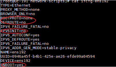
2. Restart the NIC.
[root@UC01 /]# ifdown ens192
[root@UC01 /]# ifup ens192
3. Use the ifconfig command to display network information and verify that the NIC is in up state.
Planning the networks
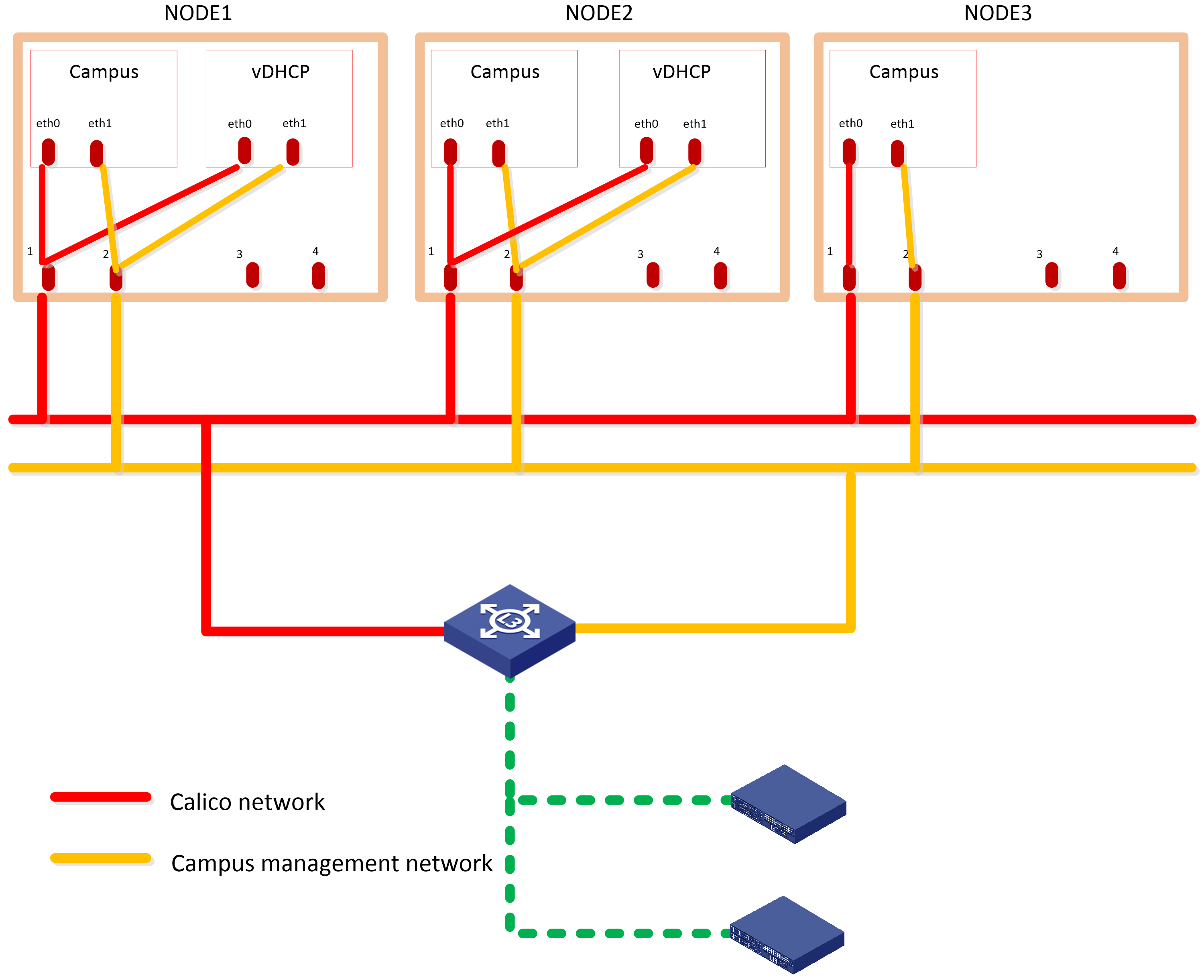
The campus scenario uses the Layer 3 network scheme, where the controller NIC IP and the two IP addresses of the device are on different subnets. In this network scheme, device in multiple fabrics can come online automatically. For the controller to provide automated underlay network deployment function, you must configure DHCP relay agent on the Layer 3 gateway device between the server that hosts the controller and the spine and leaf devices.
The solution deploys the following networks:
· Calico network—Network for containers to communicate with each other. The Calico network uses the IP address pool (177.177.0.0 by default) specified at Unified Platform cluster deployment. You do not need to configure addresses for the Calico network at component deployment. The network can share the same NIC as the MACVLAN network.
· MACVLAN network—Management network for the SeerEngine-Campus and the vDHCP components. You must plan network address pools for the MACVLAN network before deploying a component.
As a best practice, use Table 10 to calculate the number of required IP addresses in the subnet assigned to the MACVLAN network. For example, if the SeerEngine-Campus cluster has three members and the vDHCP cluster has two members, the required number of IP addresses is: (1*3+1) + (1*2+1)=7.
Table 10 IP address planning for the MACVLAN network
|
Component name |
Max cluster members |
Default cluster members |
Required addresses for SeerEngine-Campus or vDHCP |
|
SeerEngine-Campus |
32 |
3 |
1*Member quantity + 1 The additional address is reserved as the cluster IP address. |
|
vDHCP |
2 |
2 |
Deploying SeerEngine-Campus and vDHCP
The SeerEngine-Campus controller depends on specific components. Before installing SeerEngine-Campus, you must install those components. Other Unified Platform and basic network management application packages can be used as optional components. If you need a function, install the corresponding application package as needed. For the specific procedures, see H3C Unified Platform Deployment Guide.
Accessing the convergence deployment page
1. In the address bar of the browser, enter https://ip_address:8443/matrix/ui to log in to Matrix.
The ip_address parameter specifies the northbound service VIP.
2. Enter the username and password, and then click Login to enter the default Matrix cluster deployment page.
By default, the username is admin and the password is Pwd@12345. If you have changed the password when installing the operating system, enter the password as configured.
3. On the top navigation bar, click DEPLOY. From the navigation pane, select Convergence Deployment, as shown in Figure 2.
Figure 2 Convergence deployment
Uploading the installation packages
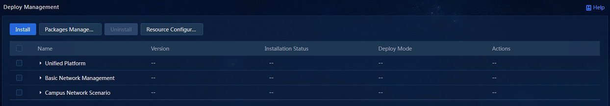
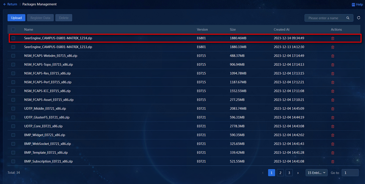
1. Click Packages Management to access the installation package management page. Click Upload to upload installation packages. On this page, you can upload and delete installation packages.
The installation package list displays names, versions, sizes, creation time, and other information of the uploaded installation packages. The application installation packages support bulk uploading. You can bulk select and upload the installation packages as needed.
2. Upload the installation packages of SeerEngine-Campus, vDHCP Server, EIA, and WSM components to the system, as shown in Figure 3.
Figure 3 Uploading installation packages
Selecting applications
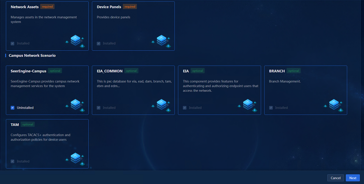
After the installation packages are uploaded, click Back to return to the convergence deployment page. Click Install to access the application selection page. Select SeerEngine-Campus and its dependent applications will be selected by default, as shown in Figure 4.
Figure 4 Selecting applications
Selecting installation packages
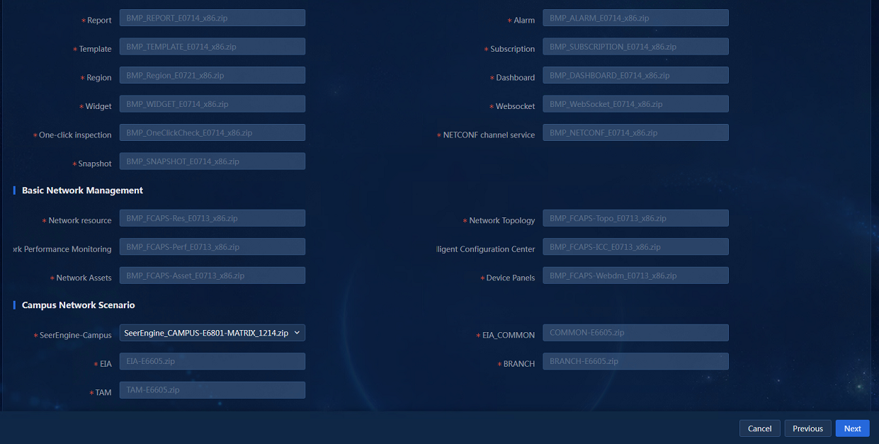
After selecting applications, click Next to access the package selection page, and select the packages as shown in Figure 5.
Figure 5 Selecting installation packages
Configuring resources
1. Click Next to access the resource configuration page, and select a resource scale.
Configuring parameters
1. Click Next to enter the parameter configuration page.
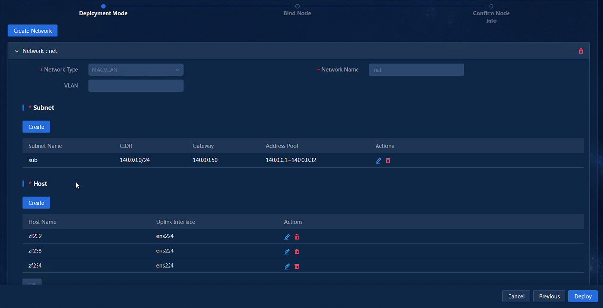
2. Click Create Network to configure network parameters.
3. Specify network information, create subnets, configure host information, and then click Next.
The controller uses the management network to manage southbound devices. Configure the following parameters as needed:
¡ VLAN—If multiple networks use the same uplink interface on a host, configure VLANs to isolate the networks. By default, no VLAN is specified.
¡ Subnet CIDR, Gateway, Address Pool—The platform uses the subnet and address pool to assign IP addresses to components and uses the gateway as the default gateway for containers.
¡ Uplink Interface—Hosts use their uplink interface for providing services to SeerEngine-Campus and vDHCP Server containers.
Figure 6 Network Configuration
|
|
NOTE: Address pool settings cannot be edited once applied. As a best practice, configure a minimum of 32 IP addresses in each address pool. |
4. Click Next to access the node binding page, as shown in Figure 7.
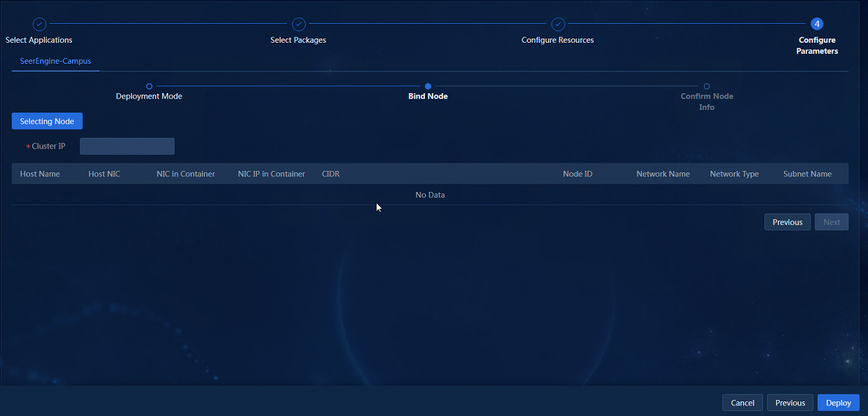
5. Click Selecting Nodes. On the network binding page that opens, bind the networks and subnets to different nodes.
Then, the subnet IP address pool is used to assign IP addresses to the nodes as shown in Figure 8.
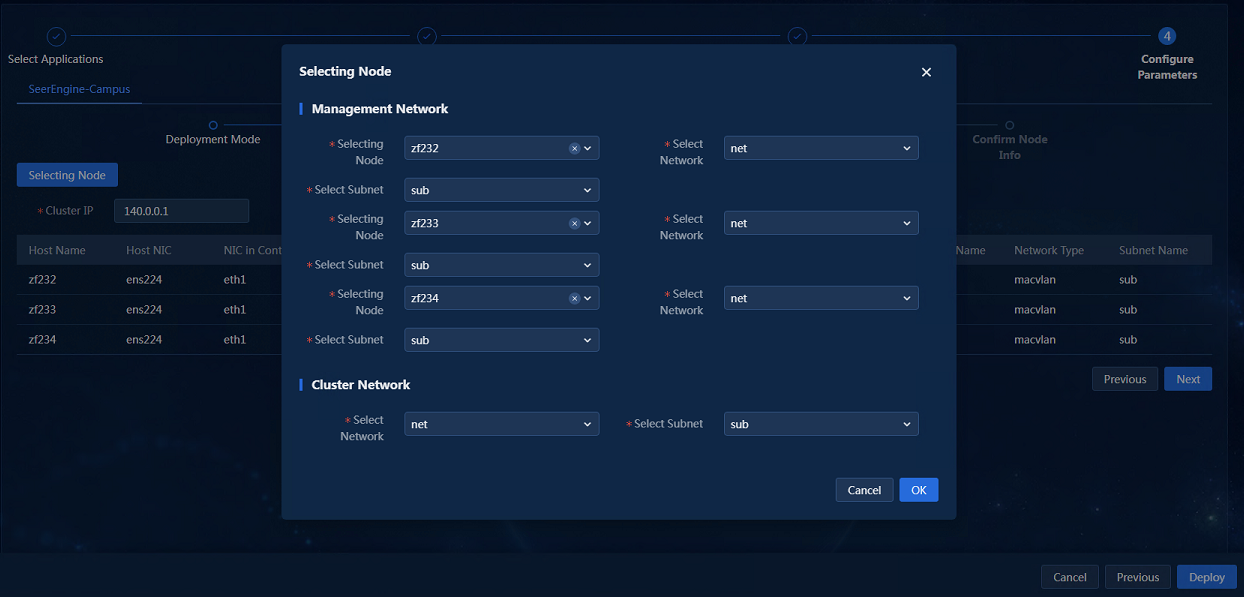
6. After the configuration is completed, click OK to return to the node binding page, as shown in Figure 9.
Figure 9 Node binding completed
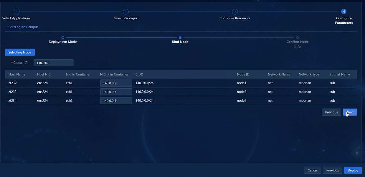
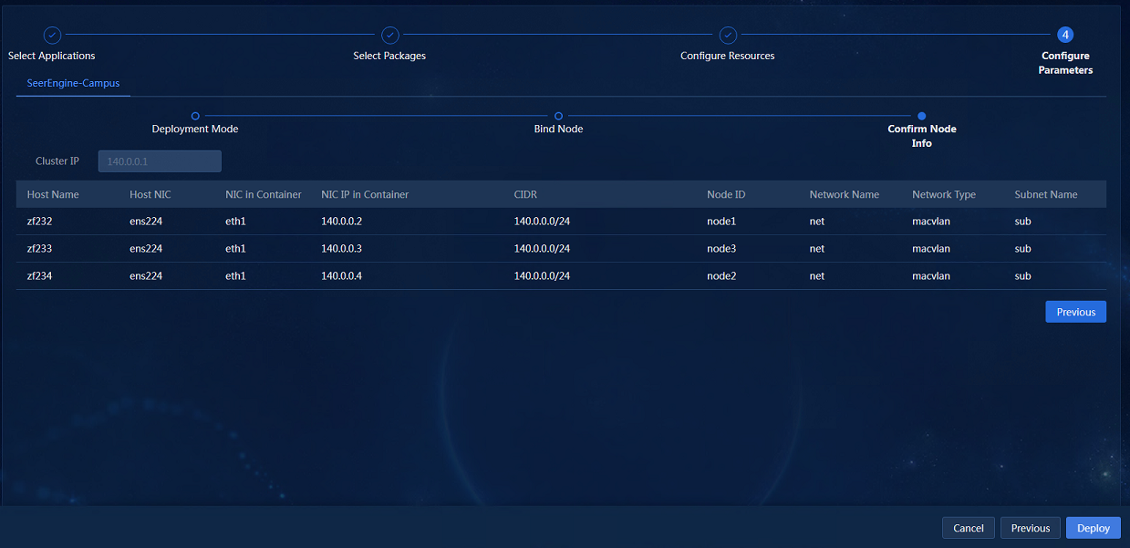
7. Click Next to access the page for confirming node information, as shown in Figure 10. You can continue to configure the parameters of other components. After you finish all configuration, click Deploy.
Figure 10 Confirming node information
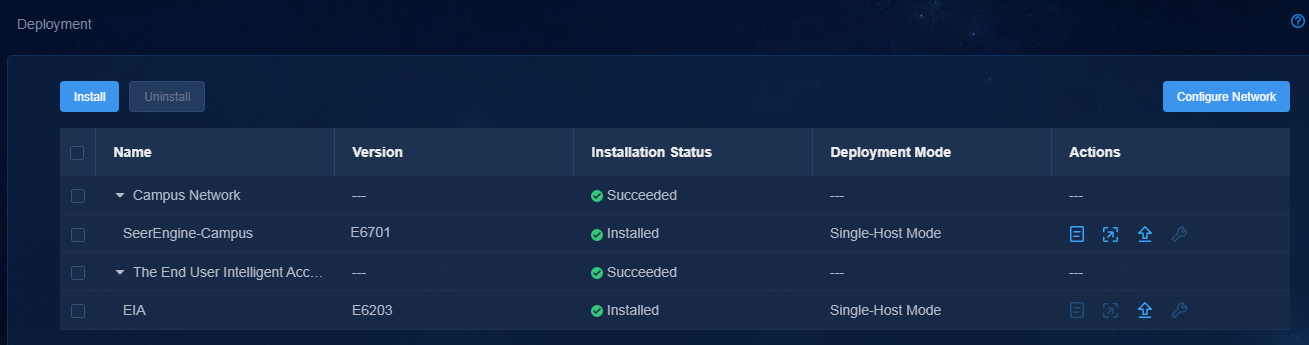
Viewing component details
1. To view detailed information about a component, click the ![]() icon
to the left of a component, and then click
icon
to the left of a component, and then click ![]() in the Actions column for that component.
in the Actions column for that component.
Figure 11 Viewing component details
Accessing the SeerEngine-Campus page
1. Enter the Unified Platform login address in your browser and then press Enter. The default login address is http://ip_address:30000/central/index.html. ip_address represents the virtual IP for the northbound service of Unified Platform. 30000 represents the port number.
2. Enter the username and password, and then click Login to enter the main Unified Platform page.
By default, the username is admin and the password is Pwd@12345. If you have changed the password when installing the operating system, enter the password as configured.
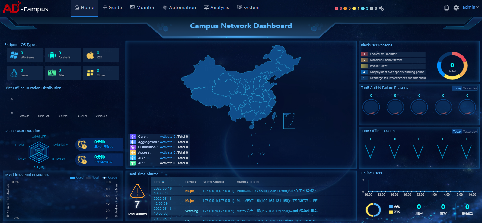
3. Click Automation on the top navigation bar and then select Campus Network from the left navigation pane to configure the campus network.
Figure 12 SeerEngine-Campus controller home page
Registering and installing licenses
After you install the controller, you can use its complete features and functions for a 90-day trial period. After the trial period expires, you must get the controller licensed. For how to license the vDHCP server, see the user guide for the vDHCP server.
Installing the activation file on the license server
For the activation file request and installation procedure, see H3C Software Products Remote Licensing Guide.
Obtaining licenses
1. Log in to the SeerEngine-Campus controller.
2. From the navigation pane, select System > License.
3. Configure the parameters for the license server as described in Table 2.
Table 11 License server parameters
|
Item |
Description |
|
IP address |
Specify the IP address configured on the license server used for internal communication in the cluster. |
|
Port number |
Specify the service port number of the license server. The default value is 5555. |
|
Username |
Specify the client username configured on the license server. |
|
Password |
Specify the client password configured on the license server. |
4. Click Connect to connect the controller to the license server.
The controller will automatically obtain licensing information after connecting to the license server.
Upgrading the controller
|
|
CAUTION: · Use SeerEngine-Campus E68XX on Unified Platform E0721 and later versions as a best practice. Deploy them on the convergence deployment page of Matrix rather than the deployment management page of Unified Platform. · If you deploy components on the deployment management page of Unified Platform, you must also upgrade or uninstall these components on the same page. · If you deploy components on the convergence deployment page of Matrix, you must also upgrade or uninstall these components on the same page. · Before performing an upgrade on the Deploy > Convergence Deployment page of Matrix, you must upload the software packages to be upgraded through the upload function on the convergence deployment page to register the new version information. Click Data Synchronization to synchronize deployment data to the convergence deployment page, and then perform upgrade based on the synchronized data. |
To upgrade controllers on the convergence deployment page:
1. Log in to Matrix. Access the Deploy > Convergence Deployment page.
2. Click the ![]() button to the
left of a component to expand the component information, and click Upgrade, as shown in Figure 13.
button to the
left of a component to expand the component information, and click Upgrade, as shown in Figure 13.
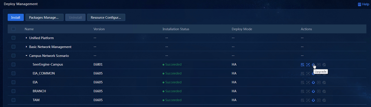
|
|
IMPORTANT: Check the controller cluster state before upgrade. Node network failure will block the upgrade. |
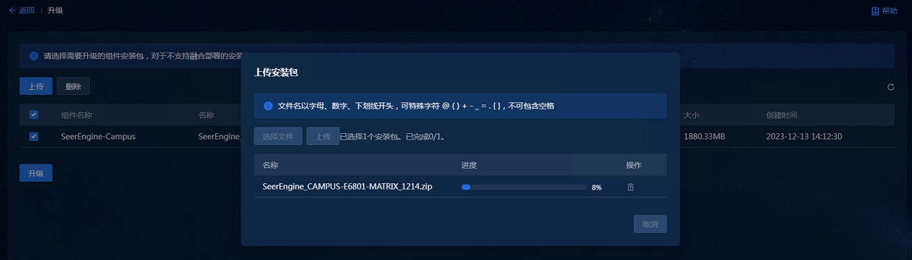
3. Access the upgrade page, and click Upload. On the page for uploading installation packages, click Select Files, and select the installation packages to be uploaded, and then click Upload to upload the packages, as shown in Figure 14.
Figure 14 Uploading installation packages
4. After the upload is completed, select the installation packages to be deployed on the upgrade page, and click Upgrade to proceed with the upgrade, as shown in Figure 15.
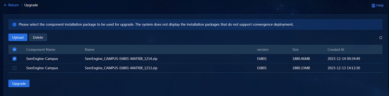
5. After the upgrade, clear the browser cache and log in to the system again as a best practice.
Uninstalling the controller
|
|
CAUTION: · Use SeerEngine-Campus E68XX on Unified Platform E0721 and later versions as a best practice. Uninstall them on the convergence deployment page of Matrix rather than the deployment management page of Unified Platform. · If you deploy or upgrade components on the deployment management page of Unified Platform, you must uninstall these components on the same page. · If you deploy or upgrade components on the convergence deployment page of Matrix, you must uninstall these components on the same page. |
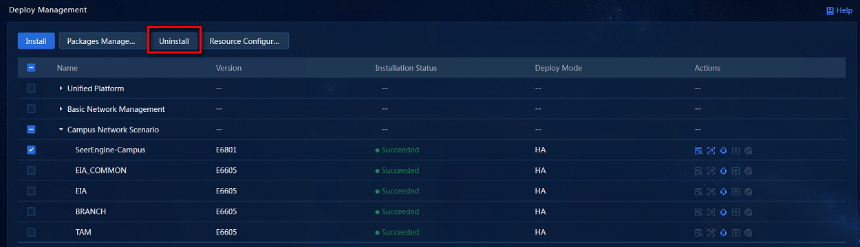
To uninstall the controller on the convergence deployment page:
1. Log in to Matrix. Access the Deploy > Convergence Deployment page.
2. Select the controller to be deleted, and click Uninstall to uninstall the controller, as shown in Figure 16.
Scaling out/in the controller
You can scale out the controller from standalone mode to cluster mode or scale out the controller in cluster mode.
Scaling out the controller from standalone mode to cluster mode
To scale out the controller from standalone mode to cluster mode, add two master nodes on Matrix to form a three-node cluster with the existing master node. Then scale out Unified Platform and the controller sequentially.
To scale out the controller from standalone mode to cluster mode:
1. Scale out Matrix. For more information, see H3C Unified Platform Deployment Guide.
2. Scale out Unified Platform. For more information, see H3C Unified Platform Deployment Guide.
3. Add network bindings.
a. Log in to Matrix. Access the Deploy > Convergence Deployment page.

a. Click the Scale Out icon in the Actions column for the SeerEngine-Campus controller to access the scale-out page, as shown in Figure 18.

a. Select the host to be scaled out, associate the network with the host uplink interfaces, and click OK. Then, click Scale Out to scale out the controller.
Scaling out the controller in cluster mode
In cluster mode, add worker nodes one by one.
To scale out the controller in cluster mode:
1. Make sure you have added worker nodes to the Matrix cluster. For more information, see H3C Unified Platform Deployment Guide.
2. Log in to Matrix. Access the Deploy > Convergence Deployment page.
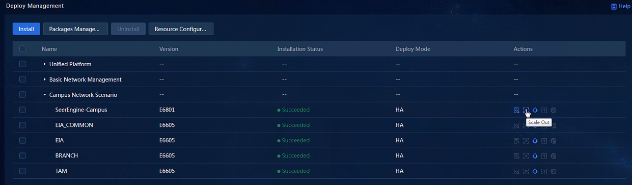
3. Click the Scale Out icon in the Actions column for the SeerEngine-Campus controller to access the scale-out page, as shown in Figure 20.
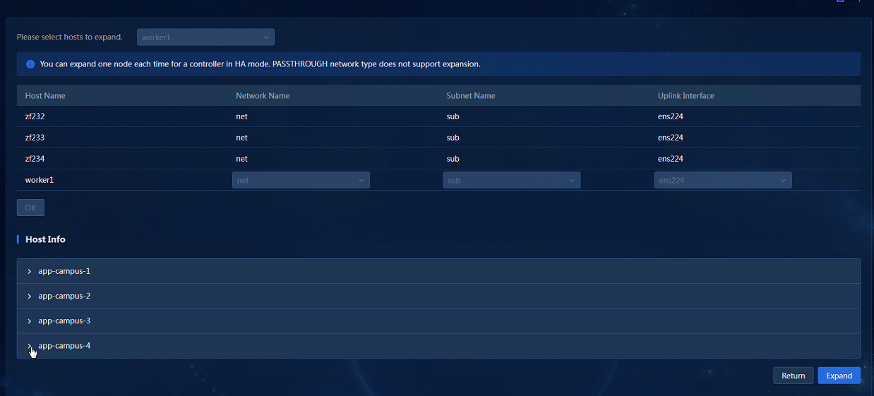
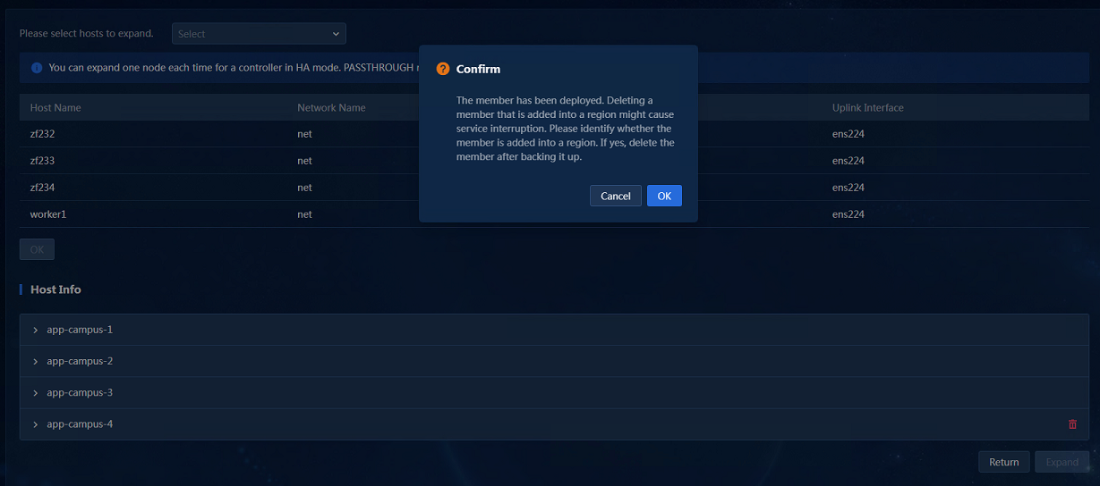
4. Select the host to be scaled out, associate the network with the host uplink interfaces, and click OK. Then, click Scale Out to scale out the controller. Only one worker node can be scaled out at a time. After the previous worker node is scaled out, access the host information area again, click the Scale Out button, and scale out the remaining worker nodes one by one.
Scaling in SeerEngine-Campus
To scale in the controller cluster, you can delete the worker nodes in the controllers cluster.
Uninstalling the scaled-out hosts
Only hosts generated by cluster scale-out can be uninstalled.
1. Log in to Matrix. Access the Deploy > Convergence Deployment
page. Select the component to be scaled in, and click the ![]() icon
the Actions column to access the scale-out page.
icon
the Actions column to access the scale-out page.
2. In the host information area, click the ![]() button
to the right of the host name. In the dialog box that opens, click OK to uninstall the scaled-out host, as shown in Figure 21.
Uninstalling deployed containers might affect service operations. You must
first back up data before uninstallation.
button
to the right of the host name. In the dialog box that opens, click OK to uninstall the scaled-out host, as shown in Figure 21.
Uninstalling deployed containers might affect service operations. You must
first back up data before uninstallation.
Figure 21 Host information area