- Table of Contents
-
- 19-Security Configuration Guide
- 00-Preface
- 01-Object group configuration
- 02-Keychain configuration
- 03-Public key management
- 04-PKI configuration
- 05-Crypto engine configuration
- 06-SSH configuration
- 07-SSL configuration
- 08-Security zone configuration
- 09-Packet filter configuration
- 10-ASPF configuration
- 11-Security policy configuration
- 12-Session management
- 13-ARP attack protection configuration
- 14-ND attack defense configuration
- 15-Attack detection and prevention configuration
- 16-mGRE configuration
- 17-Connection limit configuration
- 18-IP-based attack prevention configuration
- 19-IP source guard configuration
- 20-uRPF configuration
- 21-APR configuration
- Related Documents
-
| Title | Size | Download |
|---|---|---|
| 19-IP source guard configuration | 268.26 KB |
Contents
Configuring IP source guard (on a wired network)
IPSG bindings synchronized by routing protocols
Configuring the IPv4SG feature
Enabling IPv4SG on an interface
Configuring a static IPv4SG binding
Configuring the IPv6SG feature
Enabling IPv6SG on an interface
Configuring a static IPv6SG binding
Verifying and maintaining IPSG
Displaying IPv4SG binding information
Displaying IPv4SG bindings that can be synchronized by routing protocols
Displaying statistics about local and remote IPv4SG bindings that routing protocols synchronize
Displaying IPv6SG binding information
Displaying IPv6SG bindings that can be synchronized by routing protocols
Displaying statistics about local and remote IPv6SG bindings that routing protocols synchronize
Example: Configuring static IPv4SG
Example: Configuring DHCP relay agent-based dynamic IPv4SG
Example: Configuring static IPv6SG
Example: Configuring DHCPv6 relay agent-based dynamic IPv6SG
Configuring IP source guard (on a wireless network)
Configuring IP source guard (on a wired network)
About IPSG
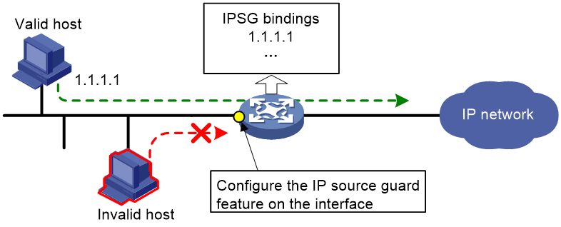
IP source guard (IPSG) prevents spoofing attacks by using an IPSG binding table to filter out illegitimate packets. This feature is typically configured on user-side interfaces.
IPSG operating mechanism
The IPSG binding table contains bindings that bind IP address, MAC address, VLAN, or any combinations. IPSG uses the bindings to match an incoming packet. If a match is found, the packet is forwarded. If no match is found, the packet is discarded.
IPSG is a per-interface packet filter. Configuring this feature on one interface does not affect packet forwarding on another interface.
IPSG bindings can be static or dynamic.
As shown in Figure 1, IPSG forwards only the packets that match an IPSG binding.
Figure 1 IPSG application
Static IPSG bindings
Static IPSG bindings are configured manually. They are suitable for scenarios where few hosts exist on a LAN and their IP addresses are manually configured. For example, you can configure a static IPSG binding on an interface that connects to a server. This binding allows the interface to receive packets only from the server.
Static IPSG bindings on an interface implement the following functions:
· Filter incoming IPv4 or IPv6 packets on the interface.
Static IPSG bindings can be global or interface-specific.
· Global static binding—Binds the IP address and MAC address in system view. The binding takes effect on all interfaces to filter packets for user spoofing attack prevention.
· Interface-specific static binding—Binds the IP address, MAC address, VLAN, or any combination of the items in interface view. The binding takes effect only on the interface to check the validity of users who are attempting to access the interface.
Dynamic IPSG bindings
IPSG automatically obtains user information from other modules to generate dynamic bindings. A dynamic IPSG binding can contain MAC address, IPv4 or IPv6 address, VLAN tag, ingress interface, and binding type. The binding type identifies the source module for the binding, such as DHCP snooping or DHCPv6 snooping.
For example, DHCP-based IPSG bindings are suitable for scenarios where hosts on a LAN obtain IP addresses through DHCP. IPSG is configured on the DHCP server or the DHCP relay agent. It generates dynamic bindings based on the client bindings on the DHCP server or the DHCP relay entries. IPSG allows only packets from the DHCP clients to pass through.
Dynamic IPv4SG
Dynamic bindings generated based on different source modules are for different usages:
|
Interface types |
Source modules |
Binding usage |
|
Layer 2 Ethernet interface |
802.1X |
Packet filtering. |
|
Layer 3 Ethernet interface VLAN interface |
DHCP relay agent |
Packet filtering. |
|
DHCP server |
For cooperation with modules (such as the authorized ARP module) to provide security services. |
For more information about 802.1X, see User Access and Authentication Configuration Guide. For information about DHCP relay agent, see the DHCP relay agent configuration in Layer 3—IP Services Configuration Guide. For information about DHCP server, see the DHCP server configuration in Layer 3—IP Services Configuration Guide.
Dynamic IPv6SG
Dynamic IPv6SG bindings generated based on different source modules are for different usages:
|
Interface types |
Source modules |
Binding usage |
|
Layer 2 Ethernet interface |
DHCPv6 snooping ND snooping 802.1X |
Packet filtering. |
|
Layer 3 Ethernet interface VLAN interface |
DHCPv6 relay agent ND RA prefix entry recording |
Packet filtering. |
For more information about DHCPv6 snooping, see Security Configuration Guide. For more information about ND snooping, see IPv6 basics configuration in Layer 3—IP Services Configuration Guide. For more information about ND RA prefix entry recording, see IPv6 neighbor discovery in Layer 3—IP Services Configuration Guide. For more information about DHCPv6 relay agent, see Layer 3—IP Services Configuration Guide.
IPSG bindings synchronized by routing protocols
In addition to static and dynamic IPSG bindings, the device also supports IPSG bindings synchronized by routing protocols (such as BGP) from remote devices. These bindings are called remote IPSG bindings. By default, the remote IPSG bindings do not have interface information and cannot be used for packet filtering. When users roam from remote devices to the local device, the device learns interface information for the remote IPSG bindings through ARP or ND entries of the users. Then, the device converts the remote IPSG bindings into local IPSG bindings and uses these bindings for packet filtering.
For more information about BGP, see BGP overview in Layer 3—IP Routing Configuration Guide.
IPSG tasks at a glance
To configure IPv4SG, perform the following tasks:
1. Enabling IPv4SG on an interface
2. (Optional.) Configuring a static IPv4SG binding
To configure IPv6SG, perform the following tasks:
1. Enabling IPv6SG on an interface
2. (Optional.) Configuring a static IPv6SG binding
Configuring the IPv4SG feature
Enabling IPv4SG on an interface
About this task
When you enable IPSG on an interface, the static and dynamic IPSG are both enabled.
· Static IPv4SG uses static bindings configured by using the ip source binding command. For more information, see "Configuring a static IPv4SG binding."
· Dynamic IPv4SG generates dynamic bindings from related source modules. IPv4SG uses the bindings to filter incoming IPv4 packets based on the matching criteria specified in the ip verify source command.
Restrictions and guidelines
To implement dynamic IPv4SG, make sure 802.1X, DHCP relay agent, or DHCP server operates correctly on the network.
Enabling IPv4SG on an interface
1. Enter system view.
system-view
2. Enter interface view.
interface interface-type interface-number
The following interface types are supported:
¡ Layer 2 Ethernet interface.
¡ Layer 3 Ethernet interface.
¡ VLAN interface.
3. Enable the IPv4SG feature.
ip verify source { ip-address | ip-address mac-address | mac-address }
By default, the IPv4SG feature is disabled on an interface.
Configuring a static IPv4SG binding
About this task
You can configure global static and interface-specific static IPv4SG bindings. Interface-specific static and dynamic bindings take priority over global static bindings. An interface first uses the static and dynamic bindings on the interface to match packets. If no match is found, the interface uses the global bindings.
Restrictions and guidelines
Global static bindings take effect on all interfaces on the device.
Configuring a global static IPv4SG binding
1. Enter system view.
system-view
2. Configure a global static IPv4SG binding.
ip source binding ip-address ip-address mac-address mac-address
Configuring a static IPv4SG binding on an interface
1. Enter system view.
system-view
2. Enter interface view.
interface interface-type interface-number
The following interface types are supported:
¡ Layer 2 Ethernet interface.
¡ Layer 3 Ethernet interface.
¡ VLAN interface.
3. Configure a static IPv4SG binding.
ip source binding { ip-address ip-address | ip-address ip-address mac-address mac-address | mac-address mac-address } [ vlan vlan-id ]
You can configure the same static IPv4SG binding on different interfaces.
Configuring the IPv6SG feature
Enabling IPv6SG on an interface
About this task
When you enable IPv6SG on an interface, the static and dynamic IPv6SG are both enabled.
· Static IPv6SG uses static bindings configured by using the ipv6 source binding command. For more information, see "Configuring a static IPv6SG binding."
· Dynamic IPv6SG generates dynamic bindings from related source modules. IPv6SG uses the bindings to filter incoming IPv6 packets based on the matching criteria specified in the ipv6 verify source command.
Restrictions and guidelines
To implement dynamic IPv6SG, make sure DHCPv6 relay agent or ND snooping operates correctly on the network.
Enabling IPv6SG on an interface
1. Enter system view.
system-view
2. Enter interface view.
interface interface-type interface-number
The following interface types are supported:
¡ Layer 2 Ethernet interface.
¡ Layer 3 Ethernet interface.
¡ VLAN interface.
3. Enable the IPv6SG feature.
ipv6 verify source { ip-address | ip-address mac-address | mac-address }
By default, the IPv6SG feature is disabled on an interface.
Configuring a static IPv6SG binding
About this task
You can configure global static and interface-specific static IPv6SG bindings. Interface-specific static and dynamic bindings take priority over global static bindings. An interface first uses the static and dynamic bindings on the interface to match packets. If no match is found, the interface uses the global bindings.
Restrictions and guidelines
Global static bindings take effect on all interfaces on the device.
Configuring a global static IPv6SG binding
1. Enter system view.
system-view
2. Configure a global static IPv6SG binding.
ipv6 source binding ip-address ipv6-address mac-address mac-address
Configuring a static IPv6SG binding on an interface
1. Enter system view.
system-view
2. Enter interface view.
interface interface-type interface-number
The following interface types are supported:
¡ Layer 2 Ethernet interface.
¡ Layer 3 Ethernet interface.
¡ VLAN interface.
3. Configure a static IPv6SG binding.
ipv6 source binding { ip-address ipv6-address | ip-address ipv6-address mac-address mac-address | mac-address mac-address } [ vlan vlan-id ]
You can configure the same static IPv6SG binding on different interfaces.
Verifying and maintaining IPSG
Displaying IPv4SG binding information
To display IPv4SG bindings, execute the following command in any view:
display ip source binding [ static | [ vpn-instance vpn-instance-name ] [ dhcp-relay | dhcp-server | dot1x ] ] [ ip-address ip-address ] [ mac-address mac-address ] [ vlan vlan-id ] [ interface interface-type interface-number ] [ slot slot-number ]
Displaying IPv4SG bindings that can be synchronized by routing protocols
Perform display tasks in any view.
· Display local IPv4SG bindings that can be synchronized by routing protocols.
display ip source binding-local [ interface interface-type interface-number ] [ dhcp-relay ] [ ip-address ip-address ] [ mac-address mac-address ] [ vlan vlan-id ] [ slot slot-number [ cpu cpu-number ] ]
· Display remote IPv4SG bindings synchronized by routing protocols.
display ip source binding-remote [ router-id router-id ] [ dhcp-relay ] [ ip-address ip-address ] [ mac-address mac-address ] [ vlan vlan-id ] [ slot slot-number [ cpu cpu-number ] ]
Displaying statistics about local and remote IPv4SG bindings that routing protocols synchronize
To display statistics about local and remote IPv4SG bindings that routing protocols synchronize, execute the following command in any view:
display ip source binding statistics
Displaying IPv6SG binding information
Perform display tasks in any view.
· Display IPv6SG address bindings.
display ipv6 source binding [ static | [ vpn-instance vpn-instance-name ] [ dhcpv6-relay | dot1x ] ] [ ip-address ipv6-address ] [ mac-address mac-address ] [ vlan vlan-id ] [ interface interface-type interface-number ] [ slot slot-number ]
Displaying IPv6SG bindings that can be synchronized by routing protocols
Perform display tasks in any view.
· Display local IPv6SG bindings that can be synchronized by routing protocols.
display ipv6 source binding-local [ interface interface-type interface-number ] [ dhcpv6-relay ] [ ip-address ipv6-address ] [ mac-address mac-address ] [ vlan vlan-id ] [ slot slot-number [ cpu cpu-number ] ]
· Display remote IPv6SG bindings synchronized by routing protocols.
display ipv6 source binding-remote [ router-id router-id ] [ dhcpv6-relay ] [ ip-address ipv6-address ] [ mac-address mac-address ] [ vlan vlan-id ] [ slot slot-number [ cpu cpu-number ] ]
Displaying statistics about local and remote IPv6SG bindings that routing protocols synchronize
To display statistics about local and remote IPv6SG bindings that routing protocols synchronize, execute the following command in any view:
display ipv6 source binding statistics
IPSG configuration examples
Example: Configuring static IPv4SG
Network configuration
As shown in Figure 2, all hosts use static IP addresses.
Configure static IPv4SG bindings on Device A and Device B to meet the following requirements:
· All interfaces of Device A allow IP packets from Host A to pass.
· GigabitEthernet 0/0/1 of Device A allows IP packets from Host B to pass.

Procedure
# Configure IP addresses for the interfaces. (Details not shown.)
# Enable IPv4SG on GigabitEthernet 0/0/2.
<DeviceA> system-view
[DeviceA] interface gigabitethernet 0/0/2
[DeviceA-GigabitEthernet0/0/2] ip verify source ip-address mac-address
[DeviceA-GigabitEthernet0/0/2] quit
# Configure a static IPv4SG binding for Host A.
[DeviceA] ip source binding ip-address 192.168.0.1 mac-address 0001-0203-0406
# Enable IPv4SG on GigabitEthernet 0/0/1.
[DeviceA] interface gigabitethernet 0/0/1
[DeviceA-GigabitEthernet0/0/1] ip verify source ip-address mac-address
# On GigabitEthernet 0/0/1, configure a static IPv4SG binding for Host B.
[DeviceA-GigabitEthernet0/0/1] ip source binding mac-address 0001-0203-0407
[DeviceA-GigabitEthernet0/0/1] quit
Verifying the configuration
# Verify that the static IPv4SG bindings are configured successfully on Device A.
<DeviceA> display ip source binding static
Total entries found: 2
IP Address MAC Address Interface VLAN Type
192.168.0.1 0001-0203-0406 N/A N/A Static
N/A 0001-0203-0407 GE0/0/1 N/A Static
Example: Configuring DHCP relay agent-based dynamic IPv4SG
Network configuration
As shown in Figure 3, DHCP relay agent is enabled on the router. The host obtains an IP address from the DHCP server through the DHCP relay agent.
Enable dynamic IPv4SG on GigabitEthernet 0/0/1 to filter incoming packets by using the IPv4SG bindings generated based on DHCP relay entries.

Procedure
1. Configure the DHCP relay agent:
# Configure IP addresses for the interfaces. (Details not shown.)
# Enable the DHCP service.
<Router> system-view
[Router] dhcp enable
# Enable recording DHCP relay client entries.
[Router] dhcp relay client-information record
# Configure interface GigabitEthernet 0/0/1 to operate in DHCP relay mode.
[Router] interface gigabitethernet 0/0/1
[Router-GigabitEthernet0/0/1] dhcp select relay
# Specify the IP address of the DHCP server.
[Router-GigabitEthernet0/0/1] dhcp relay server-address 10.1.1.1
[Router-GigabitEthernet0/0/1] quit
2. Enable IPv4SG on GigabitEthernet 0/0/1 and verify the source IP address and MAC address for dynamic IPSG.
[Router] interface gigabitethernet 0/0/1
[Router-GigabitEthernet0/0/1] ip verify source ip-address mac-address
[Router-GigabitEthernet0/0/1] quit
Verifying the configuration
# Display dynamic IPv4SG bindings generated based on DHCP relay entries.
[Router] display ip source binding dhcp-relay
Total entries found: 1
IP Address MAC Address Interface VLAN Type
192.168.0.1 0001-0203-0406 GE1/0/1 N/A DHCP relay
GigabitEthernet 0/0/1 will filter packets based on the IPv4SG binding.
Example: Configuring static IPv6SG
Network configuration
As shown in Figure 4, configure a static IPv6SG binding on GigabitEthernet 0/0/1 of the device to allow only IPv6 packets from the host to pass.

Procedure
# Enable IPv6SG on GigabitEthernet 0/0/1.
<Device> system-view
[Device] interface gigabitethernet 0/0/1
[Device-GigabitEthernet0/0/1] ipv6 verify source ip-address mac-address
# On GigabitEthernet 0/0/1, configure a static IPv6SG binding for the host.
[Device-GigabitEthernet0/0/1] ipv6 source binding ip-address 2001::1 mac-address 0001-0202-0202
[Device-GigabitEthernet0/0/1] quit
Verifying the configuration
# Verify that the static IPv6SG binding is configured successfully on the device.
[Device] display ipv6 source binding static
Total entries found: 1
IPv6 Address MAC Address Interface VLAN Type
2001::1 0001-0202-0202 GE0/0/1 N/A Static
Example: Configuring DHCPv6 relay agent-based dynamic IPv6SG
Network configuration
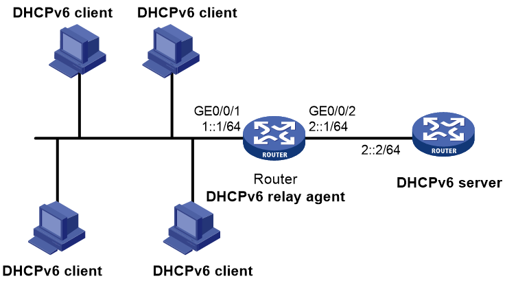
As shown in Figure 5, DHCPv6 relay agent is enabled on the router. The clients obtain IPv6 addresses from the DHCPv6 server through the DHCPv6 relay agent.
Enable dynamic IPv6SG on GigabitEthernet 0/0/1 to filter incoming packets by using the IPv6SG bindings generated based on DHCPv6 relay entries.
Procedure
1. Configure the DHCPv6 relay agent:
# Specify IP addresses for the interfaces. (Details not shown.)
# Enable the DHCPv6 relay agent on GigabitEthernet 0/0/1.
[Router] interface gigabitethernet 0/0/1
[Router-GigabitEthernet0/0/1] ipv6 dhcp select relay
# Enable recording of DHCPv6 relay entries on the interface.
[Router-GigabitEthernet0/0/1] ipv6 dhcp relay client-information record
# Specify the DHCPv6 server address 2::2 on the relay agent.
[Router-GigabitEthernet0/0/1] ipv6 dhcp relay server-address 2::2
[Router-GigabitEthernet0/0/1] quit
2. Enable IPv6SG on GigabitEthernet 0/0/1 and verify the source IP address and MAC address for dynamic IPv6SG.
[Router] interface gigabitethernet 0/0/1
[Router-GigabitEthernet0/0/1] ipv6 verify source ip-address mac-address
[Router-GigabitEthernet0/0/1] quit
Verifying the configuration
# Display dynamic IPv6SG bindings generated based on DHCPv6 relay entries.
[Router] display ipv6 source binding dhcpv6-relay
Total entries found: 1
IPv6 Address MAC Address Interface VLAN Type
1::2 0001-0203-0406 GE0/0/1 N/A DHCPv6 relay
GigabitEthernet 0/0/1 will filter packets based on the IPv6SG binding.
Configuring IP source guard (on a wireless network)
About IPSG
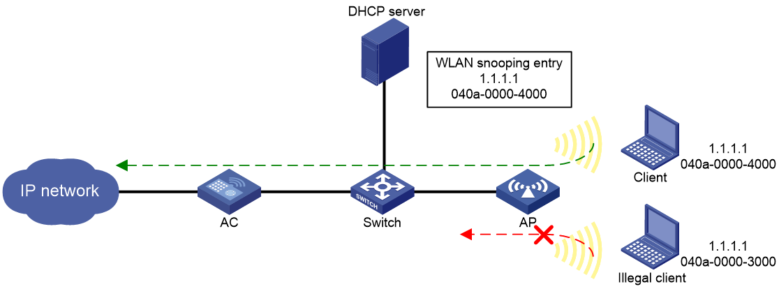
IP source guard (IPSG) prevents spoofing attacks by using WLAN snooping entries to filter packets received by an AP. It drops packets that do not match the entries.
WLAN snooping is enabled by default on the AP. A WLAN snooping entry is an IP-MAC binding.
· In an IPv4 network, WLAN snooping reads the clients' IP-MAC bindings from the ARP messages or DHCP packets that pass through the AP. IPSG uses only the WLAN snooping entries obtained through DHCP packets.
· In an IPv6 network, WLAN snooping reads the clients' IP-MAC bindings from packets that pass through the AP. The packets are RA messages, NS messages, NA messages, and DHCP packets. IPSG uses all WLAN snooping entries for packet filtering.
For information about DHCP, DHCPv6, and ND, see Layer 3—IP Services Configuration Guide.
As shown in Figure 6, the AP has a WLAN snooping entry for the client that has obtained an IP address from the DHCP server. IPSG forwards packets only from the legal client.
Configuring the IPSG feature
Restrictions and guidelines
IPSG enabled for a service template filters only packets from the clients in the BSSs created based on the service template. It does not affect clients in other BSSs.
Procedure
1. Enter system view.
system-view
2. Enter service template view.
wlan service-template service-template-number
3. Enable the IPSG feature for IPv4.
ip verify source [ alarm-only ]
By default, the IPSG feature is disabled for IPv4.
4. Enable the IPSG feature for IPv6.
ipv6 verify source [ alarm-only ]
By default, the IPSG feature is disabled for IPv6.
IPSG configuration examples
Example: Configuring IPSG
Network configuration
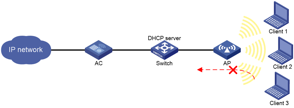
As shown in Figure 7, the clients access the WLAN through SSID service. Client 1 and Client 2 obtain IP addresses through the DHCP server (the switch).
Enable IPSG for the service template on the AC to make the AP filter incoming packets. The AP forwards the packets only from Client 1 and Client 2.
Procedure
# Create service template 1.
<AC> system-view
[AC] wlan service-template 1
# Set the SSID to service for the service template, and enable the service template.
[AC-wlan-st-1] ssid service
[AC-wlan-st-1] service-template enable
# Enable the IPSG feature for IPv4.
[AC-wlan-st-1] ip verify source
[AC-wlan-st-1] quit
# Create AP ap1 with model WA6320, and set its serial ID to 219801A28N819CE0002T.
[AC] wlan ap ap1 model WA6320
[AC-wlan-ap-ap1] serial-id 219801A28N819CE0002T
# Enter radio view of radio 2 and bind service template 1 to radio 2.
[AC-wlan-ap-ap1] radio 2
[AC-wlan-ap-ap1-radio-2] service-template 1
[AC-wlan-ap-ap1-radio-2] quit
[AC-wlan-ap-ap1] quit
Verifying the configuration
# Use Client 1 and Client 2 to obtain their IP addresses through DHCP, and manually assign Client 3 the IP address of Client 1. (Details not shown.)
# Verify that packets from Client 1 and Client 2 are allowed to pass. (Details not shown.)
# Verify that packets from Client 3 are dropped. (Details not shown.)