- Table of Contents
- Related Documents
-
| Title | Size | Download |
|---|---|---|
| 02-INT configuration | 226.58 KB |
Contents
Restrictions and guidelines: INT configuration
Enabling global INT packet dropping
Display and maintenance commands for INT
Example: Configuring common INT
Example: Configuring flexible INT
Configuring INT
About INT
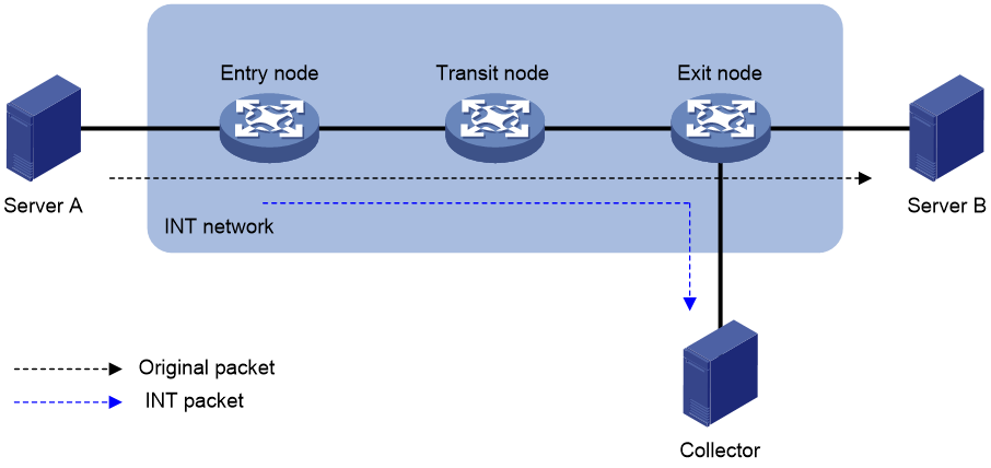
The Inband Telemetry (INT) feature is a network monitoring technology designed to collect data from the device. The device sends data to a collector in real time for device performance monitoring and network monitoring.
INT network components
As shown in Figure 1, an INT network contains the following INT-enabled devices: one entry node, one transit node, and one exit node.
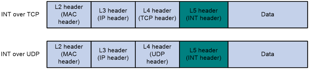
INT packet formats
INT generates INT packets by mirroring original packets, inserting INT headers, and collecting data. The INT header and collected data are in the original IP header. Therefore, an INT packet and its original packet have the same IP header and forwarding path.
The device supports generating INT packets from TCP packets and UDP packets. Figure 2 shows the INT packet formats. The 64 most significant bits of the INT header are fixed at 0xaaaaaaaabbbbbbbb, which are the INT mark.
How INT works
INT supports common INT and flexible INT. The two types of INT have the following differences:
· Common INT—Each node needs to be configured with an INT role on its input interface: ingress, transit, and egress. Traffic flows are defined on the entry node by using a QoS policy. INT flows are automatically identified on the transit node and exit node and processed according to configured actions. On each input interface in the path, you can perform INT processing only on the flows defined on the entry node.
· Flexible INT—No device role needs to be configured on each node. On each node, an ACL can be used to define a flow and an action used to take on the defined flow. For the same flow, the original packets are matched on the entry node, and the INT packets are matched on the transit node and exit node. You can define multiple flows on an interface and take different actions on different flows.
Common INT is easy to configure and is recommended. Use flexible INT only when you need to process multiple flows on an interface.
Common INT
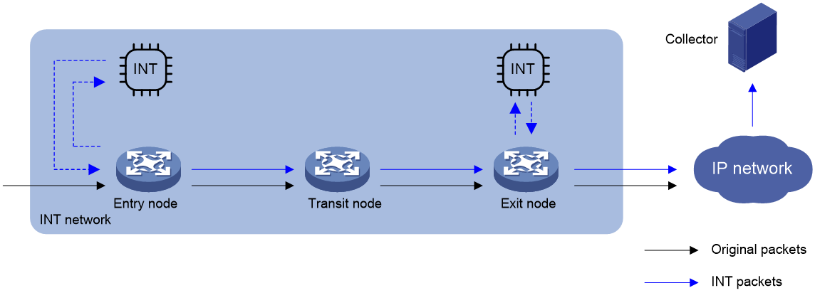
As shown in Figure 3, the nodes in common INT perform the following functions:
1. On the entry node, the ingress port uses a QoS policy to sample matching packets, and mirrors sampled packets to the INT processor. Then, the INT processor adds an INT header to the INT packet and loops it back to the ingress port. The ingress port identifies the looped-back INT packet according to the INT mark, adds collected data to it, and forwards it to the egress port. The egress port adds collected data to the INT packet and sends it to the transit node.
2. On the transit node, the ingress port identifies the INT packet according to the INT mark, adds collected data to it, and forwards it to the egress port. The egress port adds collected data to the INT packet, and sends it to the exit node.
3. On the exit node, the ingress port identifies the INT packet according to the INT mark, adds collected data to the INT packet, encapsulates the INT packet with the configured parameters, and sends it to the collector.
Flexible INT
As shown in Figure 3, the nodes in flexible INT perform the following functions:
1. On the entry node, the ingress port uses an ACL to sample matching packets, and mirrors sampled packets to the INT processor. Then, the INT processor adds an INT header to the INT packet and loops it back to the ingress port. The ingress port identifies the looped-back INT packet according to an ACL and adds collected data to it, and forwards it. The egress port adds collected data to the INT packet and sends it to the transit node.
2. On the transit node, the ingress port uses an ACL to identify INT packets, adds collected data to INT packets, and forwards them to the egress port. The egress port adds collected data to INT packets and sends them to the exit node.
3. On the exit node, the ingress port uses an ACL to identify INT packets and mirrors them to the INT processor. The INT processor encapsulates the INT packets and sends them to the collector.
Figure 3 INT network diagram
Restrictions and guidelines: INT configuration
Common INT and flexible INT can only be deployed in underlay networks.
As a best practice, configure the transit node and exit node before configuring the entry node.
The switch can act as an entry node, transit node, or exit node when the firmware resource mode is INT-PTP or INT-BFD. The switch can only act as a transit node when the firmware resource mode is PTP-BFD. You can use the hardware-resource firmware-mode command to change the firmware resource mode. For more information about firmware resource modes, see BFD in High Availability Configuration Guide.
INT is mutually exclusive with the following features:
· Mirroring configured with sampling.
· NetStream.
· IPv6 NetStream.
· NetAnalysis.
· sFlow.
· Telemetry stream.
· MOD.
For more information about mirroring, NetStream, IPv6 NetStream, NetAnalysis, and sFlow, see Network Management and Monitoring Configuration Guide.
An interface cannot be both configured as the ingress interface on an entry node and configured with iNQA. For more information about iNQA, see Network Management and Monitoring Configuration Guide.
Configuring common INT
Configuring the exit node
1. Specify a device ID.
a. Enter system view.
system-view
b. Specify a device ID for the exit node.
telemetry ifa device-id address
By default, the exit node does not have a device ID.
2. Execute the following commands in sequence to specify the interface as the egress interface:
interface interface-type interface-number
telemetry ifa role egress
quit
By default, no interface role is configured.
3. Configure addressing parameters to encapsulate in INT packets sent to the collector.
telemetry ifa collector source source-address destination dest-address source-port port destination-port port [ vlan vlan-id ]
By default, no addressing parameters are configured for INT packets.
4. Enable INT globally.
telemetry ifa global enable
By default, INT is enabled globally.
Configuring the transit node
1. Specify a device ID.
a. Enter system view.
system-view
b. Specify a device ID for the transit node.
telemetry ifa device-id address
By default, the transit node does not have a device ID.
2. Execute the following commands in sequence to specify the interface as the transit interface:
interface interface-type interface-number
telemetry ifa role transit
quit
By default, no interface role is configured.
3. Enable INT globally.
telemetry ifa global enable
By default, INT is enabled globally.
Configuring the entry node
1. Specify a device ID.
a. Enter system view.
system-view
b. Specify a device ID for the entry node.
telemetry ifa device-id address
By default, the entry node does not have a device ID.
2. Configure the ingress interface.
a. Enter interface view.
interface interface-type interface-number
b. Specify the interface as the ingress interface.
telemetry ifa role ingress
By default, an interface is not used as the ingress interface.
c. Return to system view
quit
3. Enable internal loopback on an interface.
a. Enter interface view.
interface interface-type interface-number
b. Enable internal loopback on the interface.
telemetry ifa loopback
By default, internal loopback is disabled on an interface.
Enable internal loopback on any interface that is in the same port group as the ingress port. To view port grouping information, execute the display qos-acl resource command. Ports under the same Interfaces field are in the same port group.
c. Return to system view
quit
Only the S6805, S6825, and S9850 switch series support internal loopback.
If internal loopback is enabled on an interface, the device supports a maximum of three mirroring groups. For more information about mirroring groups, see mirroring in Network Management and Monitoring Configuration Guide.
4. Mirror packets to the INT processor.
a. Execute the following commands in sequence to define a traffic class:
traffic classifier classifier-name [ operator { and | or } ]
if-match match-criteria
quit
For more information about the if-match command, see QoS commands in ACL and QoS Command Reference.
b. Execute the following commands in sequence to define a traffic behavior:
traffic behavior behavior-name
mirror-to ifa-processor [ sampler sampler-name ]
quit
For more information about the mirror-to command, see mirroring commands in Network Management and Monitoring Command Reference.
c. Execute the following commands in sequence to define a QoS policy:
qos [ mirroring ] policy policy-name
classifier classifier-name behavior behavior-name
quit
d. Execute the following commands in sequence to apply the QoS policy to the inbound direction of an interface:
interface interface-type interface-number
qos apply [ mirroring ] policy policy-name inbound
quit
5. Enable INT globally.
telemetry ifa global enable
By default, INT is enabled globally.
Configuring flexible INT
Configuring the exit node
Configuring a device ID
1. Specify a device ID.
a. Enter system view.
system-view
b. Specify a device ID for the exit node.
telemetry ifa device-id address
By default, the exit node does not have a device ID.
Configuring the interface role
1. Enter system view.
system-view
2. Configure the interface role as egress.
a. Create a user-defined ACL and enter user-defined ACL view.
For information about the acl configuration command, see ACL commands in ACL and QoS Command Reference.
b. Configure a rule for the user-defined ACL.
For information about the rule (user-defined ACL view) configuration command, see ACL commands in ACL and QoS Command Reference.
If the entry node uses an ACL when mirroring packets to the INT processor, the ACLs used for any other action on any node must have the same identification attributes plus an attribute to identify the INT flag. The identification attributes and the attribute to identify the INT flag must be in the same rule. For example, the rule in the ACL used on the entry node is rule permit tcp source 10.0.0.3 0, the rule in the ACL used for any other action must be rule permit tcp source 10.0.0.3 0 ifa l5 aaaaaaaabbbbbbbb ffffffffffffffff 0.
c. Return to system view.
quit
d. Enter interface view.
interface interface-type interface-number
e. Configure the action of mirroring incoming INT packets on the ingress port to the INT processor and dropping the original INT packets.
telemetry ifa ifa-id acl user-defined { acl-number | name acl-name } action mirror-to-processor drop
By default, no action is configured.
f. Return to system view.
quit
By default, no interface role is configured.
Configuring addressing parameters and INT status
1. Enter system view.
system-view
2. Configure addressing parameters to encapsulate in INT packets sent to the collector.
telemetry ifa collector source source-address destination dest-address source-port port destination-port port [ vlan vlan-id ]
By default, no addressing parameters are configured for INT packets.
3. Enable INT globally.
telemetry ifa global enable
By default, INT is enabled globally.
Configuring the transit node
Configuring a device ID
1. Specify a device ID.
a. Enter system view.
system-view
b. Specify a device ID for the transit node.
telemetry ifa device-id address
By default, the transit node does not have a device ID.
Configuring the interface role
1. Enter system view.
system-view
2. Configure the action of adding collected data to INT packets on the input interface.
a. Create a user-defined ACL and enter user-defined ACL view.
For information about the acl configuration command, see ACL commands in ACL and QoS Command Reference.
b. Configure a rule for the user-defined ACL.
For information about the rule (user-defined ACL view) configuration command, see ACL commands in ACL and QoS Command Reference.
If the entry node uses an ACL when mirroring packets to the INT processor, the ACLs used for any other action on any node must have the same identification attributes plus an attribute to identify the INT flag. The identification attributes and the attribute to identify the INT flag must be in the same rule. For example, the rule in the ACL used on the entry node is rule permit tcp source 10.0.0.3 0, the rule in the ACL used for any other action must be rule permit tcp source 10.0.0.3 0 ifa l5 aaaaaaaabbbbbbbb ffffffffffffffff 0.
c. Return to system view.
quit
d. Enter interface view.
interface interface-type interface-number
e. Configure the action of adding collected data to INT packets.
telemetry ifa ifa-id acl user-defined { acl-number | name acl-name } action add-metadata
By default, no action is configured.
f. Return to system view.
quit
By default, no interface role is configured.
Configuring INT status
1. Enter system view.
system-view
2. Enable INT globally.
telemetry ifa global enable
By default, INT is enabled globally.
Configuring the entry node
1. Specify a device ID.
a. Enter system view.
system-view
b. Specify a device ID for the entry node.
telemetry ifa device-id address
By default, the entry node does not have a device ID.
2. Mirror original packets on the ingress port to the INT processor.
a. Create an IPv4, Layer 2, or user-defined ACL and enter ACL view.
For information about the acl configuration command, see ACL commands in ACL and QoS Command Reference.
b. Configure a rule for the ACL.
For information about the rule configuration command, see ACL commands in ACL and QoS Command Reference.
c. Return to system view.
quit
d. Enter interface view.
interface interface-type interface-number
e. Configure the action of mirroring original packets on the ingress port to the INT processor.
telemetry ifa ifa-id [ acl [ mac | user-defined ]{ acl-number | name acl-name } ] action mirror-to-processor [ sampler sampler-name ]
By default, no action is configured.
f. Return to system view.
quit
3. Enable internal loopback on an interface.
a. Enter interface view.
interface interface-type interface-number
b. Enable internal loopback on the interface.
telemetry ifa loopback
By default, internal loopback is disabled on an interface.
c. Return to system view
quit
Only the S6805, S6825, and S9850 switch series support internal loopback.
If internal loopback is enabled on an interface, the device supports a maximum of three mirroring groups. For more information about mirroring groups, see mirroring in Network Management and Monitoring Configuration Guide.
4. Add collected data to local loopback traffic on the ingress port.
a. Create a user-defined ACL and enter user-defined ACL view.
For information about the acl configuration command, see ACL commands in ACL and QoS Command Reference.
b. Configure a rule for the user-defined ACL.
For information about the rule (user-defined ACL view) configuration command, see ACL commands in ACL and QoS Command Reference.
If the entry node uses an ACL when mirroring packets to the INT processor, the ACLs used for any other action on any node must have the same identification attributes plus an attribute to identify the INT flag. The identification attributes and the attribute to identify the INT flag must be in the same rule. For example, the rule in the ACL used on the entry node is rule permit tcp source 10.0.0.3 0, the rule in the ACL used for any other action must be rule permit tcp source 10.0.0.3 0 ifa l5 aaaaaaaabbbbbbbb ffffffffffffffff 0.
c. Return to system view.
quit
d. Enter interface view.
interface interface-type interface-number
e. Configure the action of adding collected data to local loopback traffic.
telemetry ifa ifa-id acl user-defined { acl-number | name acl-name } local-loopback action add-metadata
By default, no action is configured.
f. Return to system view.
quit
5. Enable INT globally.
telemetry ifa global enable
By default, INT is enabled globally.
Enabling global INT packet dropping
About this task
Perform this task if you do not want to send INT packets to the downstream node.
Procedure
1. Enter system view.
system-view
2. Enable global INT packet dropping.
telemetry ifa global packet-drop
By default, global INT packet dropping is disabled.
Display and maintenance commands for INT
Execute display commands in any view.
|
Task |
Command |
|
Display information about QoS policies applied to interfaces (see ACL and QoS Command Reference). |
display qos [ mirroring ] policy interface [ interface-type interface-number ] [ slot slot-number ] inbound |
|
Display INT configuration. |
display telemetry ifa |
INT configuration examples
Example: Configuring common INT
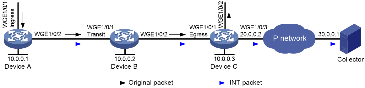
Network configuration
As shown in Figure 4, configure common INT to test the link delay.
Procedure
1. Assign IP addresses to interfaces and configure routes. Make sure the network connections are available. (Details not shown.)
2. Configure Device C:
# Specify 10.0.0.3 as the device ID of the exit node.
[DeviceC] telemetry ifa device-id 10.0.0.3
# Specify Twenty-FiveGigE 1/0/1 as the egress interface.
[DeviceC] interface twenty-fivegige 1/0/1
[DeviceC-Twenty-FiveGigE1/0/1] telemetry ifa role egress
[DeviceC-Twenty-FiveGigE1/0/1] quit
# Configure addressing parameters to encapsulate in INT packets sent to the collector.
[DeviceC] telemetry ifa collector source 20.0.0.2 destination 30.0.0.1 source-port 12 destination-port 14
# Enable INT globally.
[DeviceC] telemetry ifa global enable
3. Configure Device B:
# Specify 10.0.0.2 as the device ID of the transit node.
<DeviceB> system-view
[DeviceB] telemetry ifa device-id 10.0.0.2
# Specify Twenty-FiveGigE 1/0/1 as the transit interface.
[DeviceB] interface twenty-fivegige 1/0/1
[DeviceB-Twenty-FiveGigE1/0/1] telemetry ifa role transit
[DeviceB-Twenty-FiveGigE1/0/1] quit
# Enable INT globally.
[DeviceB] telemetry ifa global enable
4. Configure Device A:
# Specify 10.0.0.1 as the device ID of the entry node.
<DeviceA> system-view
[DeviceA] telemetry ifa device-id 10.0.0.1
# Specify Twenty-FiveGigE 1/0/1 as the ingress interface.
[DeviceA] interface twenty-fivegige 1/0/1
[DeviceA-Twenty-FiveGigE1/0/1] telemetry ifa role ingress
[DeviceA-Twenty-FiveGigE1/0/1] quit
# Enable internal loopback on Twenty-FiveGigE 1/0/3. You can enable internal loopback on any interface that is in the same port group as the ingress port.
[DeviceA] interface twenty-fivegige 1/0/3
[DeviceA-Twenty-FiveGigE1/0/3] telemetry ifa loopback
[DeviceA-Twenty-FiveGigE1/0/3] quit
# Create a sampler named samp in random sampling mode, and set the sampling rate to 8. One packet from 256 packets is selected.
<DeviceA> system-view
[DeviceA] sampler samp mode random packet-interval n-power 8
# Create a traffic class named classifier1, and use destination MAC address a08c-fdd7-fd99 as the match criterion in the traffic class.
[DeviceA] traffic classifier classifier1
[DeviceA-classifier-classifier1] if-match destination-mac a08c-fdd7-fd99
[DeviceA-classifier-classifier1] quit
# Create a traffic behavior named behavior1, and configure the action of mirroring traffic to the INT processor.
[DeviceA] traffic behavior behavior1
[DeviceA-behavior-behavior1] mirror-to ifa-processor sampler samp
[DeviceA-behavior-behavior 1] quit
# Create a QoS policy named ifa1, and associate traffic class classifier1 with traffic behavior behavior1 in the QoS policy.
[DeviceA] qos policy ifa1
[DeviceA-qospolicy-ifa1] classifier classifier1 behavior behavior1
[DeviceA-qospolicy-ifa1] quit
# Apply QoS policy ifa1 to the incoming traffic of Twenty-FiveGigE 1/0/1.
[DeviceA] interface twenty-fivegige 1/0/1
[DeviceA-Twenty-FiveGigE1/0/1] qos apply policy ifa1 inbound
[DeviceA-Twenty-FiveGigE1/0/1] quit
# Enable INT globally.
[DeviceA] telemetry ifa global enable
Verify the configuration
# Verify the configuration on Device A.
[DeviceA] display qos policy interface twenty-fivegige 1/0/1 inbound
Interface: Twenty-FiveGigE1/0/1
Direction: Inbound
Policy: ifa1
Classifier: classifier1
Operator: AND
Rule(s) :
If-match destination-mac a08c-fdd7-fd99
Behavior: behavior1
Mirroring:
Mirror to the ifa-processor sampler samp
[DeviceA] display telemetry ifa
Telemetry ifa status : Enabled
Telemetry ifa packet-drop : Disabled
Telemetry ifa device-id : 10.0.0.1
Telemetry ifa role:
Twenty-FiveGigE1/0/1: Ingress
Telemetry ifa loopback:
Twenty-FiveGigE1/0/3
# Verify the configuration on Device B.
[DeviceB] display telemetry ifa
Telemetry ifa status : Enabled
Telemetry ifa packet-drop : Disabled
Telemetry ifa device-id : 10.0.0.2
Telemetry ifa role:
Twenty-FiveGigE1/0/1: Transit
# Verify the configuration on Device C.
[DeviceC] display telemetry ifa
Telemetry ifa status : Enabled
Telemetry ifa packet-drop : Disabled
Telemetry ifa device-id : 10.0.0.3
Telemetry ifa role:
Twenty-FiveGigE1/0/1: Egress
Telemetry ifa collector:
Source IP: 20.0.0.2
Destination IP: 30.0.0.1
Source-port: 12
Destination-port: 14
Example: Configuring flexible INT
Network configuration
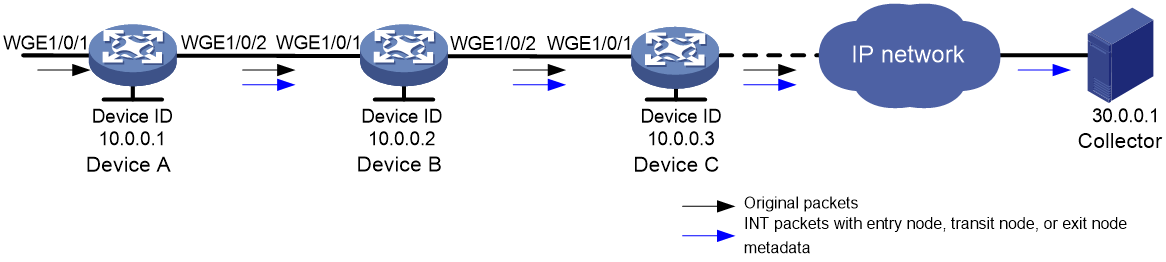
As shown in Figure 5, configure flexible INT to meet the following requirements:
· Device C sends INT packets carrying entry node data and transit node data to the collector.
· Device C sends INT packets carrying exit node data and original packets to the IP network, which sends the INT packets carrying exit node data to the collector.
Procedure
1. Assign IP addresses to interfaces and configure routes. Make sure the network connections are available. (Details not shown.)
2. Configure Device C:
# Specify 10.0.0.3 as the device ID of the exit node.
<DeviceC> system-view
[DeviceC] telemetry ifa device-id 10.0.0.3
# Create user-defined ACL 5000, and configure a rule to match INT packets with source IP address 192.168.1.2.
[DeviceC] acl user-defined 5000
[DeviceC-acl-user-5000] rule permit tcp source 192.168.1.2 0 ifa l5 aaaaaaaabbbbbbbb ffffffffffffffff 0
[DeviceC-acl-user-5000] rule permit udp source 192.168.1.2 0 ifa l5 aaaaaaaabbbbbbbb ffffffffffffffff 0
[DeviceC-acl-user-5000] quit
# Configure the action of mirroring incoming INT packets on Twenty-FiveGigE 1/0/1 to the INT processor and dropping the original INT packets.
[DeviceC] interface twenty-fivegige 1/0/1
[DeviceC-Twenty-FiveGigE1/0/1] telemetry ifa 1 acl user-defined 5000 action mirror-to-processor drop
[DeviceC-Twenty-FiveGigE1/0/1] quit
# Configure addressing parameters to encapsulate in INT packets sent to the collector.
[DeviceC] telemetry ifa collector source 20.0.0.2 destination 30.0.0.1 source-port 12 destination-port 14
# Enable INT globally.
[DeviceC] telemetry ifa global enable
3. Configure Device B:
# Specify 10.0.0.2 as the device ID of the transit node.
<DeviceB> system-view
[DeviceB] telemetry ifa device-id 10.0.0.2
# Create user-defined ACL 5000, and configure a rule to match INT packets with source IP address 192.168.1.2.
[DeviceB] acl user-defined 5000
[DeviceB-acl-user-5000] rule permit tcp source 192.168.1.2 0 ifa l5 aaaaaaaabbbbbbbb ffffffffffffffff 0
[DeviceB-acl-user-5000] rule permit udp source 192.168.1.2 0 ifa l5 aaaaaaaabbbbbbbb ffffffffffffffff 0
[DeviceB-acl-user-5000] quit
# Configure the action of mirroring INT packets on Twenty-FiveGigE 1/0/1 to the INT processor.
[DeviceB] interface twenty-fivegige 1/0/1
[DeviceB-Twenty-FiveGigE1/0/1] telemetry ifa 1 acl user-defined 5000 action add-metadata
[DeviceB-Twenty-FiveGigE1/0/1] quit
# Enable INT globally.
[DeviceB] telemetry ifa global enable
4. Configure Device A:
# Specify 10.0.0.1 as the device ID of the entry node.
<DeviceA> system-view
[DeviceA] telemetry ifa device-id 10.0.0.1
# Create a sampler named samp in random sampling mode, and set the sampling rate to 8. One packet from 256 packets is selected.
[DeviceA] sampler samp mode random packet-interval n-power 8
# Create IPv4 basic ACL 2000, and configure a rule to match packets with source IP address 192.168.1.2.
[DeviceA] acl basic 2000
[DeviceA-acl-ipv4-basic-2000] rule permit source 192.168.1.2 0
[DeviceA-acl-ipv4-basic-2000] quit
# Configure the action of mirroring original packets on Twenty-FiveGigE 1/0/1 to the INT processor.
[DeviceA] interface twenty-fivegige 1/0/1
[DeviceA-Twenty-FiveGigE1/0/1] telemetry ifa 2 acl 2000 action mirror-to-processor sampler samp
[DeviceA-Twenty-FiveGigE1/0/1] quit
# Enable internal loopback on Twenty-FiveGigE 1/0/3.
[DeviceA] interface twenty-fivegige 1/0/3
[DeviceA-Twenty-FiveGigE1/0/3] telemetry ifa loopback
[DeviceA-Twenty-FiveGigE1/0/3] quit
# Create user-defined ACL 5000, and configure a rule to match INT packets with source IP address 192.168.1.2.
[DeviceA] acl user-defined 5000
[DeviceA-acl-user-5000] rule permit tcp source 192.168.1.2 0 ifa l5 aaaaaaaabbbbbbbb ffffffffffffffff 0
[DeviceA-acl-user-5000] rule permit udp source 192.168.1.2 0 ifa l5 aaaaaaaabbbbbbbb ffffffffffffffff 0
[DeviceA-acl-user-5000] quit
# Configure the action of adding collected data to local loopback traffic.
[DeviceA] interface twenty-fivegige 1/0/1
[DeviceA-Twenty-FiveGigE1/0/1] telemetry ifa 3 acl user-defined 5000 local-loopback action add-metadata
[DeviceA-Twenty-FiveGigE1/0/1] quit
# Enable INT globally.
[DeviceA] telemetry ifa global enable
Verify the configuration
# Verify the configuration on Device A.
[DeviceA] display telemetry ifa
Telemetry ifa status : Enabled
Telemetry ifa packet-drop : Disabled
Telemetry ifa device-id : 10.0.0.1
Telemetry ifa action:
Twenty-FiveGigE1/0/1:
Telemetry ifa 1 acl 2000 action mirror-to-processor sampler samp
Telemetry ifa 2 acl user-defined 5000 local-loopback action add-metadata
Telemetry ifa loopback:
Twenty-FiveGigE1/0/3
# Verify the configuration on Device B.
[DeviceB] display telemetry ifa
Telemetry ifa status : Enabled
Telemetry ifa packet-drop : Disabled
Telemetry ifa device-id : 10.0.0.2
Telemetry ifa action:
Twenty-FiveGigE1/0/1:
Telemetry ifa 1 acl user-defined 5000 action add-metadata
# Verify the configuration on Device C.
[DeviceC] display telemetry ifa
Telemetry ifa status : Enabled
Telemetry ifa packet-drop : Disabled
Telemetry ifa device-id : 10.0.0.3
Telemetry ifa action:
Twenty-FiveGigE1/0/1:
Telemetry ifa 1 acl user-defined 5000 action mirror-to-processor drop
Telemetry ifa collector:
Source IP: 20.0.0.2
Destination IP: 30.0.0.1
Source-port: 12
Destination-port: 14
