- Table of Contents
- Related Documents
-
| Title | Size | Download |
|---|---|---|
| 03-Limiting Internal-to-External Access Configuration Examples (Web) | 812.23 KB |
Limiting Internal-to-External Access Configuration Examples
Copyright © 2024 New H3C Technologies Co., Ltd. All rights reserved.
No part of this manual may be reproduced or transmitted in any form or by any means without prior written consent of New H3C Technologies Co., Ltd.
Except for the trademarks of New H3C Technologies Co., Ltd., any trademarks that may be mentioned in this document are the property of their respective owners.
The information in this document is subject to change without notice.
Introduction
The following information provides a configuration example for limiting internal-to-external access.
Prerequisites
This document is not restricted to specific software or hardware versions. Procedures and information in the examples might be slightly different depending on the software or hardware version of the device.
The configuration examples were created and verified in a lab environment, and all the devices were started with the factory default configuration. When you are working on a live network, make sure you understand the potential impact of every command on your network.
The following information is provided based on the assumption that you have basic knowledge of VLAN and security features.
Configuration example
Network configuration
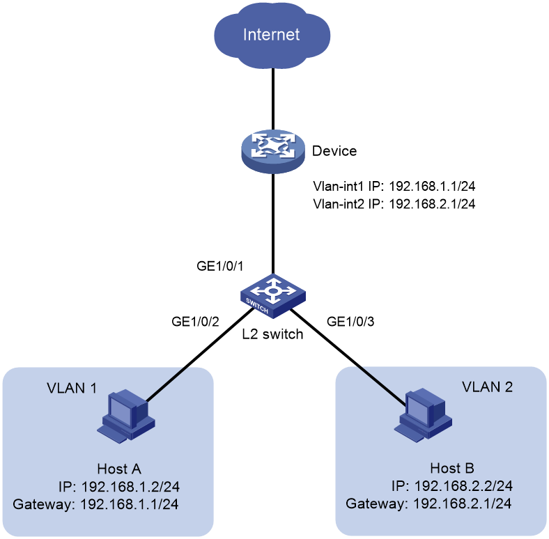
As shown in Figure 1, Host A and Host B are connected to the L2 switch. Host A belongs to VLAN 1 and Host B belongs to VLAN 2. On the device, the IP address of VLAN interface 1 is 192.168.1.1/24, and the IP address of VLAN interface 2 is 192.168.2.1/24. Configure the switch and the device to allow Host A to access the Internet and prevent Host B from accessing the Internet.
Software versions used
This example is applicable to ER3200G3, ER3260G3, and ER5200G3 series routers of the H3C Comware 7 platform. This document takes version R0136 of the H3C ER3200G3 product as an example. The specific operations might differ by product model and software version.
Procedure
1. Configure Host A and Host B:
# Assign IP address 192.168.2.2/24 to Host A, and configure its gateway address as 192.168.2.1/24. Assign IP address 192.168.3.2/24 to Host B, and configure its gateway address as 192.168.3.1/24.
2. Configure the L2 switch:
# Create VLAN 2, and assign GigabitEthernet 1/0/3 to VLAN 2.
<L2_Switch> system-view
[L2_Switch] vlan 2
[L2_Switch-vlan2] port gigabitethernet 1/0/3
[L2_Switch-vlan2] quit
# Configure GigabitEthernet 1/0/1 as a trunk port, and assign it to VLAN 1 and VLAN 2.
[L2_Switch] interface gigabitethernet 1/0/1
[L2_Switch-GigabitEthernet1/0/1] port link-type trunk
[L2_Switch-GigabitEthernet1/0/1] port trunk permit vlan 1 to 2
3. Configure the device:
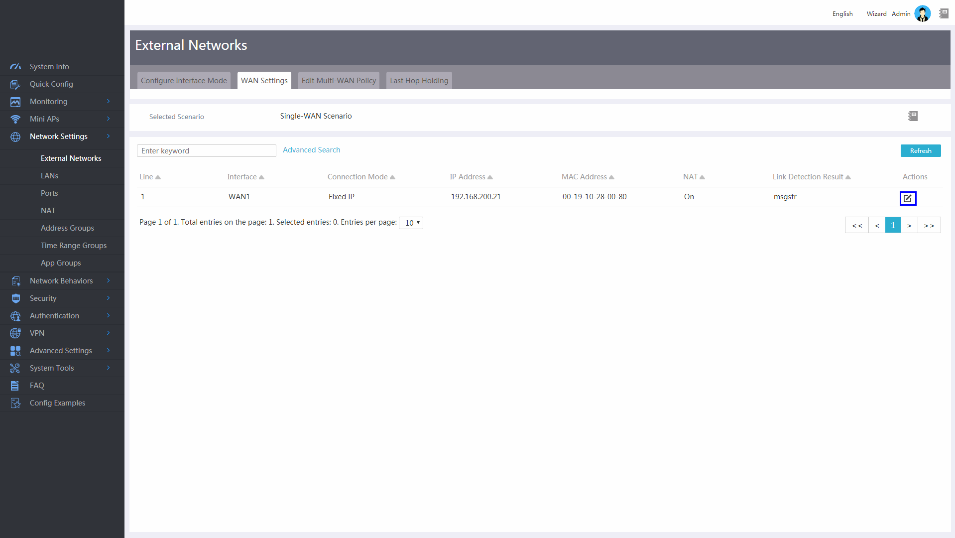
# Log in to the Web interface. From the navigation pane, select Network Settings > External Networks. Click the WAN Settings tab, and click the edit icon in the Actions column for the WAN1 interface.
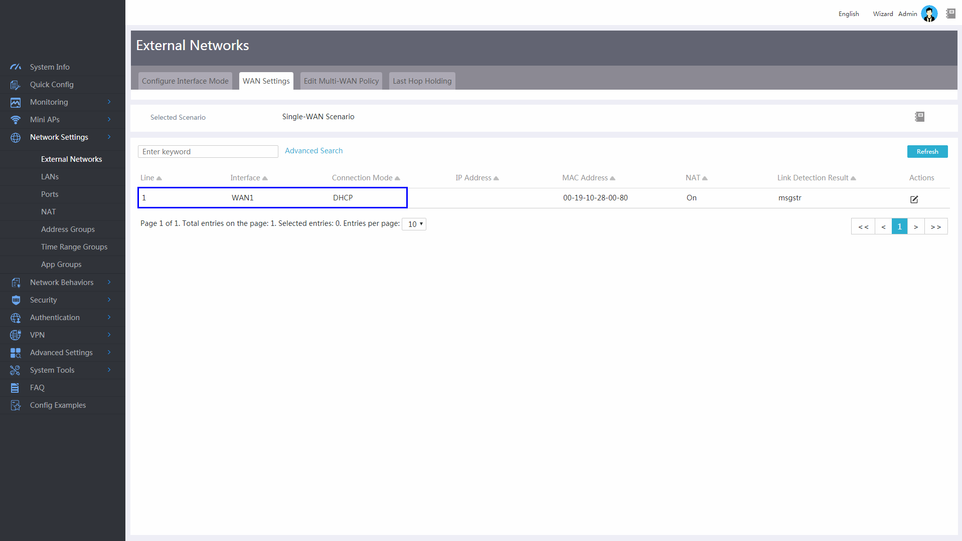
# Select DHCP from the Connection Mode list, and click Apply.
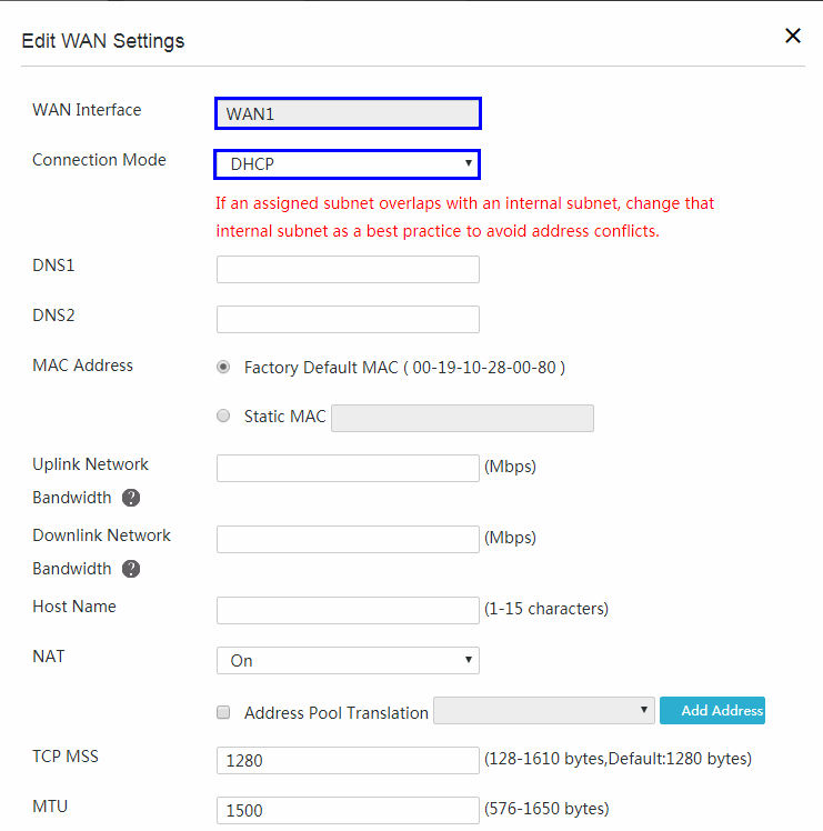
After configuration, the system prompts the Configured successfully message.
For the 192.168.1.0/24 subnet to access the Internet, make sure the subnet from which the WAN1 interface obtains an IP address through DHCP does not conflicts with it.
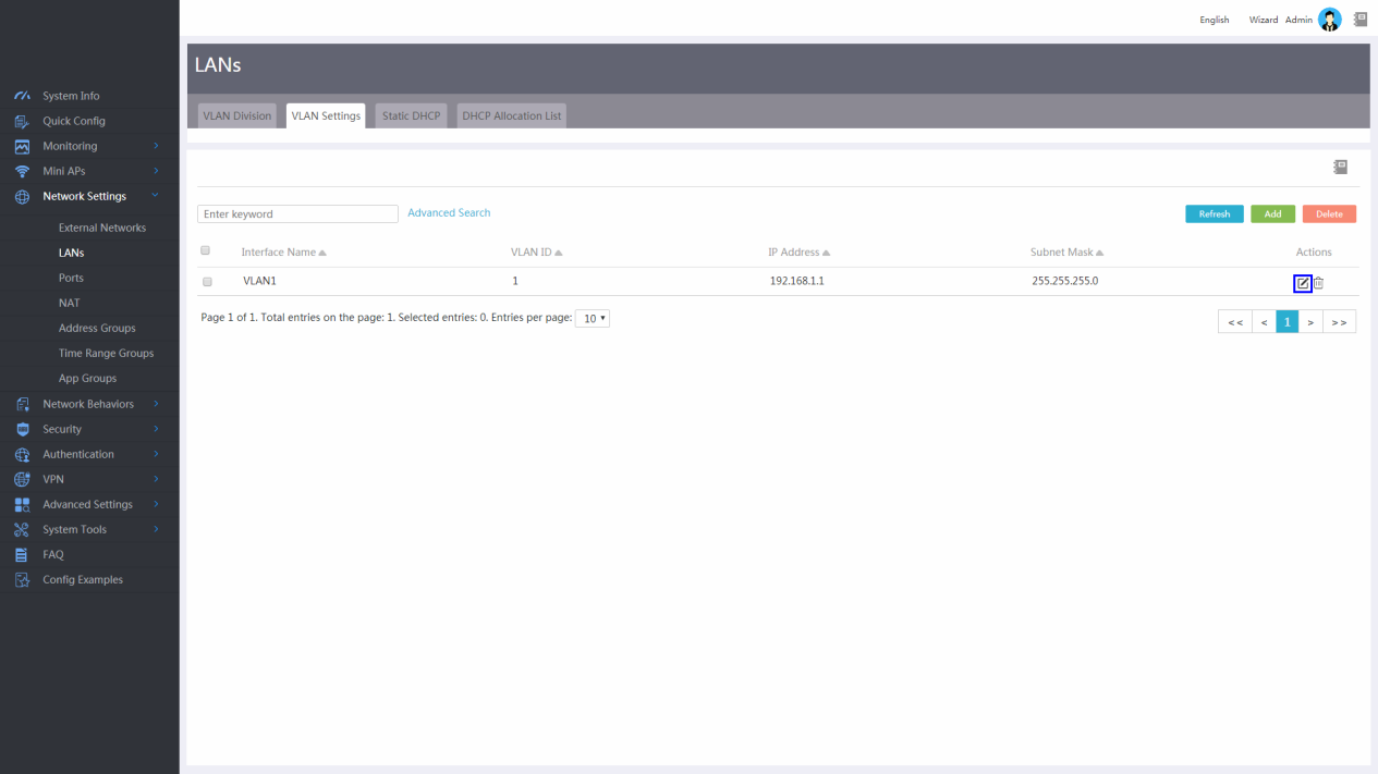
# From the navigation pane, select Network Settings > LANs. Click the VLAN Settings tab, and click the edit icon in the Actions column to edit the settings of the VLAN1 interface or use its default settings.
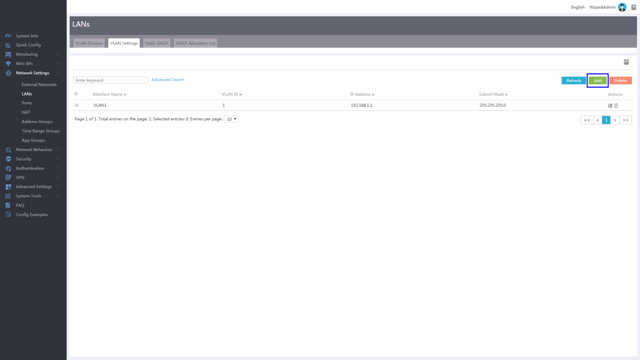
# On the VLAN Settings tab, click Add to add a VLAN.
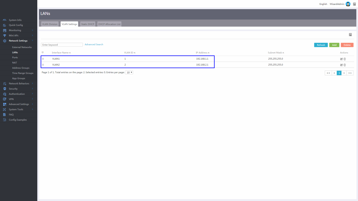
# Enter VLAN ID 2, enter IP address 192.168.2.1 and subnet mask 255.255.255.0 for the corresponding VLAN interface, select Enable DHCP, and click Apply.

After configuration, the system prompts the Configured successfully message.
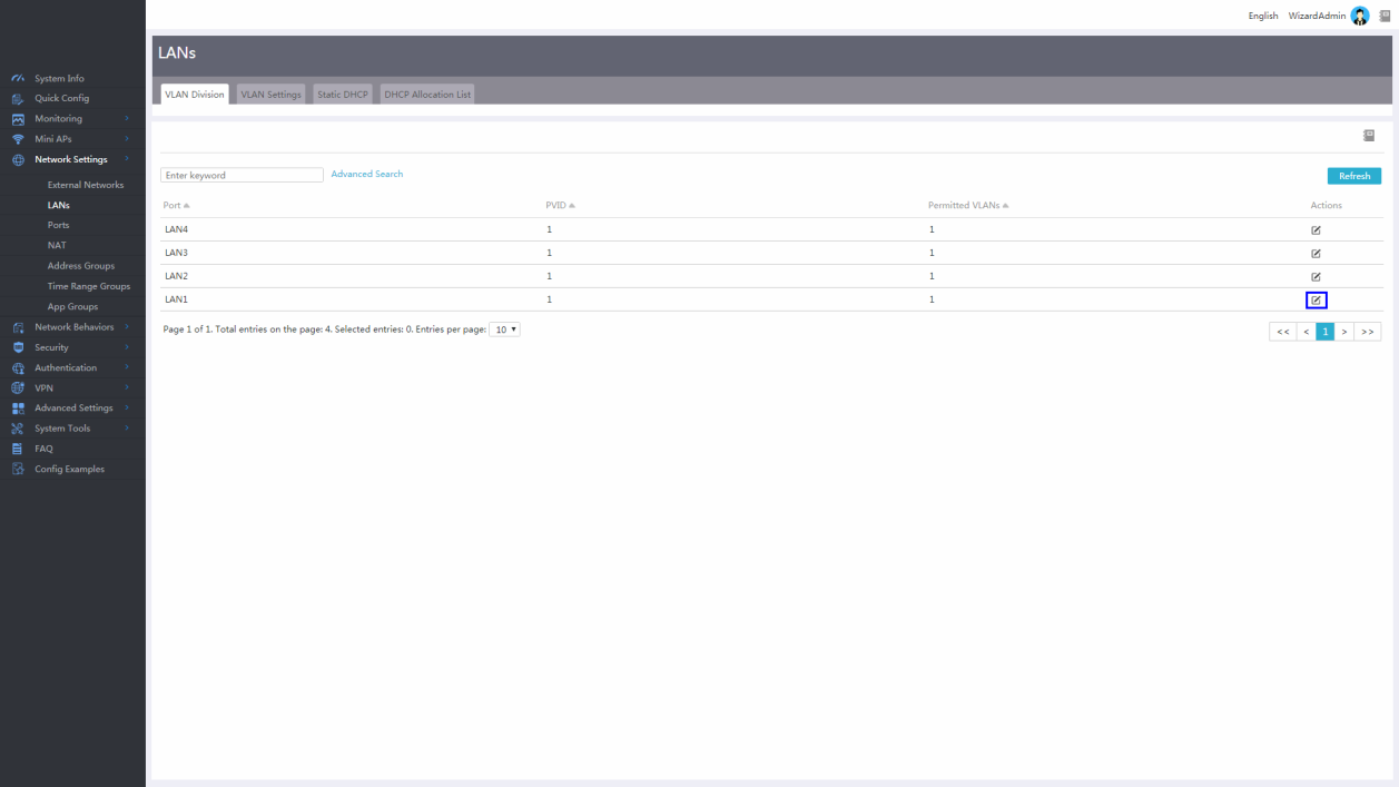
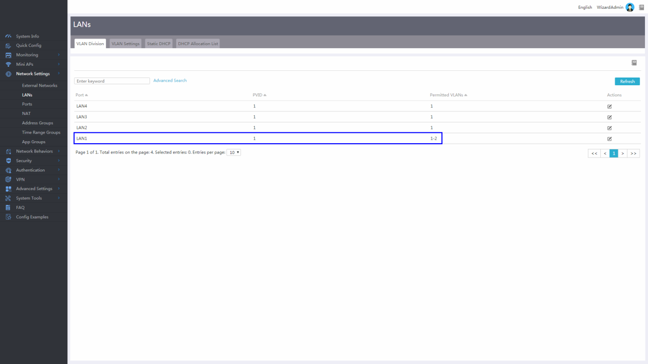
# On the VLAN Division tab, click the edit icon to edit the settings of the LAN1 port, which is connected to the L2 switch.
# On the Detailed Port Settings dialog box, add VLAN 2 from Available VLANs to Selected VLANs.

# Click Apply.

After configuration, the system prompts the Configured successfully message.
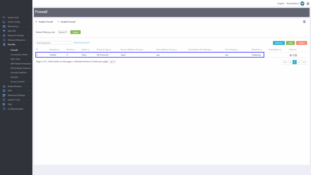
# From the left navigation pane, select Security > Firewall. Select Enable Firewall, and click Add to add a security rule.

# On the Add Security Rule dialog box, select VLAN2 from the Interface list, select All Protocols from the Protocol list, and click Add Address Group.

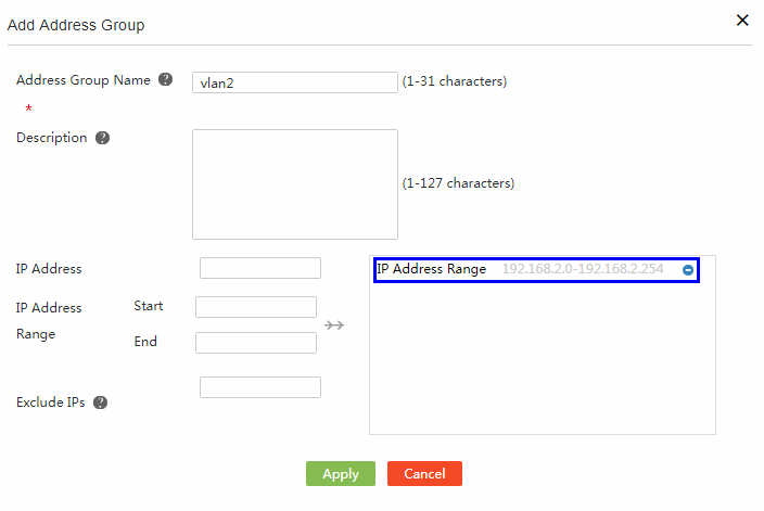
# On the Add Address Group dialog box, enter address group name vlan2, enter start IP address 192.168.2.0 and end IP address 192.168.2.254, and move the specified IP address range to the right box.
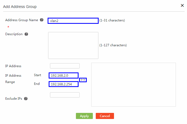
# Click Apply.
# On the Add Security Rule dialog box, select vlan2 from the Source Address Group list, select the Deny action, select Auto for the Priority field, and click Apply.
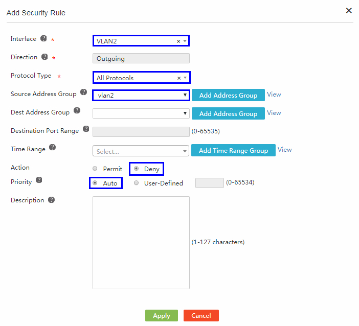
After configuration, the system prompts the Configured successfully message.
Verifying the configuration
Verify that Host A can access the Internet and Host B cannot access the Internet.
